Adapter assembly including a removable trocar assembly
Williams Dec
U.S. patent number 10,507,039 [Application Number 16/171,468] was granted by the patent office on 2019-12-17 for adapter assembly including a removable trocar assembly. This patent grant is currently assigned to Covidien LP. The grantee listed for this patent is Covidien LP. Invention is credited to Justin Williams.


View All Diagrams
| United States Patent | 10,507,039 |
| Williams | December 17, 2019 |
Adapter assembly including a removable trocar assembly
Abstract
An adapter assembly for connecting a loading unit to a handle assembly is provided. The adapter assembly includes a sleeve, a trocar assembly releasably securable with the sleeve, and a locking mechanism configured to releasably secure the trocar assembly within the sleeve.
| Inventors: | Williams; Justin (Southbury, CT) | ||||||||||
|---|---|---|---|---|---|---|---|---|---|---|---|
| Applicant: |
|
||||||||||
| Assignee: | Covidien LP (Mansfield,
MA) |
||||||||||
| Family ID: | 56990315 | ||||||||||
| Appl. No.: | 16/171,468 | ||||||||||
| Filed: | October 26, 2018 |
Prior Publication Data
| Document Identifier | Publication Date | |
|---|---|---|
| US 20190059934 A1 | Feb 28, 2019 | |
Related U.S. Patent Documents
| Application Number | Filing Date | Patent Number | Issue Date | ||
|---|---|---|---|---|---|
| 14865602 | Sep 25, 2015 | 10111684 | |||
| Current U.S. Class: | 1/1 |
| Current CPC Class: | A61B 17/115 (20130101); A61B 17/072 (20130101); A61B 17/1155 (20130101); A61B 17/3417 (20130101); A61B 2017/07214 (20130101); A61B 17/0644 (20130101); A61B 2017/00464 (20130101); A61B 2090/0813 (20160201); A61B 2017/347 (20130101); A61B 2017/00473 (20130101); A61B 2017/0046 (20130101); A61B 17/07207 (20130101); A61B 2017/00477 (20130101); A61B 17/068 (20130101) |
| Current International Class: | A61B 17/072 (20060101); A61B 17/115 (20060101); A61B 17/34 (20060101); A61B 90/00 (20160101); A61B 17/068 (20060101); A61B 17/064 (20060101); A61B 17/00 (20060101) |
| Field of Search: | ;227/19,175.2,176.1 ;606/139,153,213,219 |
References Cited [Referenced By]
U.S. Patent Documents
| 3193165 | July 1965 | Akhalaya et al. |
| 3388847 | June 1968 | Kasulin et al. |
| 3552626 | January 1971 | Astafiev et al. |
| 3638652 | February 1972 | Kelley |
| 3771526 | November 1973 | Rudie |
| 4198982 | April 1980 | Fortner et al. |
| 4207898 | June 1980 | Becht |
| 4289133 | September 1981 | Rothfuss |
| 4304236 | December 1981 | Conta et al. |
| 4319576 | March 1982 | Rothfuss |
| 4350160 | September 1982 | Kolesov et al. |
| 4351466 | September 1982 | Noiles |
| 4379457 | April 1983 | Gravener et al. |
| 4473077 | September 1984 | Noiles et al. |
| 4476863 | October 1984 | Kanshin et al. |
| 4485817 | December 1984 | Swiggett |
| 4488523 | December 1984 | Shichman |
| 4505272 | March 1985 | Utyamyshev et al. |
| 4505414 | March 1985 | Filipi |
| 4520817 | June 1985 | Green |
| 4550870 | November 1985 | Krumme et al. |
| 4573468 | March 1986 | Conta et al. |
| 4576167 | March 1986 | Noiles |
| 4592354 | June 1986 | Rothfuss |
| 4603693 | August 1986 | Conta et al. |
| 4606343 | August 1986 | Conta et al. |
| 4632290 | December 1986 | Green et al. |
| 4646745 | March 1987 | Noiles |
| 4665917 | May 1987 | Clanton et al. |
| 4667673 | May 1987 | Li |
| 4671445 | June 1987 | Barker et al. |
| 4700703 | October 1987 | Resnick et al. |
| 4703887 | November 1987 | Clanton et al. |
| 4708141 | November 1987 | Inoue et al. |
| 4717063 | January 1988 | Ebihara |
| 4752024 | June 1988 | Green et al. |
| 4754909 | July 1988 | Barker et al. |
| 4776506 | October 1988 | Green |
| 4817847 | April 1989 | Redtenbacher et al. |
| 4873977 | October 1989 | Avant et al. |
| 4893662 | January 1990 | Gervasi |
| 4903697 | February 1990 | Resnick et al. |
| 4907591 | March 1990 | Vasconcellos et al. |
| 4917114 | April 1990 | Green et al. |
| 4957499 | September 1990 | Lipatov et al. |
| 4962877 | October 1990 | Hervas |
| 5005749 | April 1991 | Aranyi |
| 5042707 | August 1991 | Taheri |
| 5047039 | September 1991 | Avant et al. |
| 5104025 | April 1992 | Main et al. |
| 5119983 | June 1992 | Green et al. |
| 5122156 | June 1992 | Granger et al. |
| 5139513 | August 1992 | Segato |
| 5158222 | October 1992 | Green et al. |
| 5188638 | February 1993 | Tzakis |
| 5193731 | March 1993 | Aranyi |
| 5197648 | March 1993 | Gingold |
| 5197649 | March 1993 | Bessler et al. |
| 5205459 | April 1993 | Brinkerhoff et al. |
| 5221036 | June 1993 | Takase |
| 5222963 | June 1993 | Brinkerhoff et al. |
| 5253793 | October 1993 | Green et al. |
| 5261920 | November 1993 | Main et al. |
| 5271543 | December 1993 | Grant et al. |
| 5271544 | December 1993 | Fox et al. |
| 5275322 | January 1994 | Brinkerhoff et al. |
| 5282810 | February 1994 | Allen et al. |
| 5285944 | February 1994 | Green et al. |
| 5285945 | February 1994 | Brinkerhoff et al. |
| 5292053 | March 1994 | Bilotti et al. |
| 5309927 | May 1994 | Welch |
| 5312024 | May 1994 | Grant et al. |
| 5314435 | May 1994 | Green et al. |
| 5314436 | May 1994 | Wilk |
| 5330486 | July 1994 | Wilk |
| 5333773 | August 1994 | Main et al. |
| 5344059 | September 1994 | Green et al. |
| 5346115 | September 1994 | Perouse et al. |
| 5348259 | September 1994 | Blanco et al. |
| 5350104 | September 1994 | Main et al. |
| 5355897 | October 1994 | Pietrafitta et al. |
| 5360154 | November 1994 | Green |
| 5368215 | November 1994 | Green et al. |
| 5392979 | February 1995 | Green et al. |
| 5395030 | March 1995 | Kuramoto et al. |
| 5403333 | April 1995 | Kaster et al. |
| 5404870 | April 1995 | Brinkerhoff et al. |
| 5411508 | May 1995 | Bessler et al. |
| 5425738 | June 1995 | Gustafson et al. |
| 5433721 | July 1995 | Hooven et al. |
| 5437684 | August 1995 | Calabrese et al. |
| 5439156 | August 1995 | Grant et al. |
| 5443198 | August 1995 | Viola et al. |
| 5447514 | September 1995 | Gerry et al. |
| 5454825 | October 1995 | Van Leeuwen et al. |
| 5464415 | November 1995 | Chen |
| 5470006 | November 1995 | Rodak |
| 5474223 | December 1995 | Viola et al. |
| 5497934 | March 1996 | Brady et al. |
| 5503635 | April 1996 | Sauer et al. |
| 5522534 | June 1996 | Viola et al. |
| 5533661 | July 1996 | Main et al. |
| 5588579 | December 1996 | Schnut et al. |
| 5609285 | March 1997 | Grant et al. |
| 5626591 | May 1997 | Kockerling et al. |
| 5632433 | May 1997 | Grant et al. |
| 5639008 | June 1997 | Gallagher et al. |
| 5641111 | June 1997 | Ahrens et al. |
| 5658300 | August 1997 | Bito et al. |
| 5669918 | September 1997 | Balazs et al. |
| 5685474 | November 1997 | Seeber |
| 5709335 | January 1998 | Heck |
| 5715987 | February 1998 | Kelley et al. |
| 5718360 | February 1998 | Green et al. |
| 5720755 | February 1998 | Dakov |
| 5732872 | March 1998 | Bolduc et al. |
| 5749896 | May 1998 | Cook |
| 5758814 | June 1998 | Gallagher et al. |
| 5799857 | September 1998 | Robertson et al. |
| 5814055 | September 1998 | Knodel et al. |
| 5833698 | November 1998 | Hinchliffe et al. |
| 5836503 | November 1998 | Ehrenfels et al. |
| 5839639 | November 1998 | Sauer et al. |
| 5855312 | January 1999 | Toledano |
| 5860581 | January 1999 | Robertson et al. |
| 5868760 | February 1999 | McGuckin, Jr. |
| 5881943 | March 1999 | Heck et al. |
| 5915616 | June 1999 | Viola et al. |
| 5947363 | September 1999 | Bolduc et al. |
| 5951576 | September 1999 | Wakabayashi |
| 5957363 | September 1999 | Heck |
| 5993468 | November 1999 | Rygaard |
| 6024748 | February 2000 | Manzo et al. |
| 6050472 | April 2000 | Shibata |
| 6053390 | April 2000 | Green et al. |
| 6068636 | May 2000 | Chen |
| 6083241 | July 2000 | Longo et al. |
| 6102271 | August 2000 | Longo et al. |
| 6117148 | September 2000 | Ravo et al. |
| 6119913 | September 2000 | Adams et al. |
| 6126058 | October 2000 | Adams et al. |
| 6142933 | November 2000 | Longo et al. |
| 6149667 | November 2000 | Hovland et al. |
| 6176413 | January 2001 | Heck et al. |
| 6179195 | January 2001 | Adams et al. |
| 6193129 | February 2001 | Bittner et al. |
| 6203553 | March 2001 | Robertson et al. |
| 6209773 | April 2001 | Bolduc et al. |
| 6241140 | June 2001 | Adams et al. |
| 6253984 | July 2001 | Heck et al. |
| 6258107 | July 2001 | Balazs et al. |
| 6264086 | July 2001 | McGuckin, Jr. |
| 6269997 | August 2001 | Balazs et al. |
| 6273897 | August 2001 | Dalessandro et al. |
| 6279809 | August 2001 | Nicolo |
| 6302311 | October 2001 | Adams et al. |
| 6338737 | January 2002 | Toledano |
| 6343731 | February 2002 | Adams et al. |
| 6387105 | May 2002 | Gifford, III et al. |
| 6398795 | June 2002 | McAlister et al. |
| 6402008 | June 2002 | Lucas |
| 6439446 | August 2002 | Perry et al. |
| 6443973 | September 2002 | Whitman |
| 6450390 | September 2002 | Heck et al. |
| 6478210 | November 2002 | Adams et al. |
| 6488197 | December 2002 | Whitman |
| 6491201 | December 2002 | Whitman |
| 6494877 | December 2002 | Odell et al. |
| 6503259 | January 2003 | Huxel et al. |
| 6517566 | February 2003 | Hovland et al. |
| 6520398 | February 2003 | Nicolo |
| 6533157 | March 2003 | Whitman |
| 6551334 | April 2003 | Blatter et al. |
| 6578751 | June 2003 | Hartwick |
| 6585144 | July 2003 | Adams et al. |
| 6588643 | July 2003 | Bolduc et al. |
| 6592596 | July 2003 | Geitz |
| 6601749 | August 2003 | Sullivan et al. |
| 6605078 | August 2003 | Adams |
| 6605098 | August 2003 | Nobis et al. |
| 6626921 | September 2003 | Blatter et al. |
| 6629630 | October 2003 | Adams |
| 6631837 | October 2003 | Heck |
| 6632227 | October 2003 | Adams |
| 6632237 | October 2003 | Ben-David et al. |
| 6652542 | November 2003 | Blatter et al. |
| 6659327 | December 2003 | Heck et al. |
| 6676671 | January 2004 | Robertson et al. |
| 6681979 | January 2004 | Whitman |
| 6685079 | February 2004 | Sharma et al. |
| 6695198 | February 2004 | Adams et al. |
| 6695199 | February 2004 | Whitman |
| 6698643 | March 2004 | Whitman |
| 6716222 | April 2004 | McAlister et al. |
| 6716233 | April 2004 | Whitman |
| 6726697 | April 2004 | Nicholas et al. |
| 6742692 | June 2004 | Hartwick |
| 6743244 | June 2004 | Blatter et al. |
| 6763993 | July 2004 | Bolduc et al. |
| 6769590 | August 2004 | Vresh et al. |
| 6769594 | August 2004 | Orban, III |
| 6820791 | November 2004 | Adams |
| 6821282 | November 2004 | Perry et al. |
| 6827246 | December 2004 | Sullivan et al. |
| 6840423 | January 2005 | Adams et al. |
| 6843403 | January 2005 | Whitman |
| 6846308 | January 2005 | Whitman et al. |
| 6852122 | February 2005 | Rush |
| 6866178 | March 2005 | Adams et al. |
| 6872214 | March 2005 | Sonnenschein et al. |
| 6874669 | April 2005 | Adams et al. |
| 6884250 | April 2005 | Monassevitch et al. |
| 6905504 | June 2005 | Vargas |
| 6938814 | September 2005 | Sharma et al. |
| 6942675 | September 2005 | Vargas |
| 6945444 | September 2005 | Gresham et al. |
| 6953138 | October 2005 | Dworak et al. |
| 6957758 | October 2005 | Aranyi |
| 6959851 | November 2005 | Heinrich |
| 6978922 | December 2005 | Bilotti et al. |
| 6981941 | January 2006 | Whitman et al. |
| 6981979 | January 2006 | Nicolo |
| 7032798 | April 2006 | Whitman et al. |
| 7059331 | June 2006 | Adams et al. |
| 7059510 | June 2006 | Orban, III |
| 7077856 | July 2006 | Whitman |
| 7080769 | July 2006 | Vresh et al. |
| 7086267 | August 2006 | Dworak et al. |
| 7114642 | October 2006 | Whitman |
| 7118528 | October 2006 | Piskun |
| 7122044 | October 2006 | Bolduc et al. |
| 7128748 | October 2006 | Mooradian et al. |
| 7141055 | November 2006 | Abrams et al. |
| 7168604 | January 2007 | Milliman et al. |
| 7179267 | February 2007 | Nolan et al. |
| 7182239 | February 2007 | Myers |
| 7195142 | March 2007 | Orban, III |
| 7207168 | April 2007 | Doepker et al. |
| 7220237 | May 2007 | Gannoe et al. |
| 7234624 | June 2007 | Gresham et al. |
| 7235089 | June 2007 | McGuckin, Jr. |
| RE39841 | September 2007 | Bilotti et al. |
| 7285125 | October 2007 | Viola |
| 7303106 | December 2007 | Milliman et al. |
| 7303107 | December 2007 | Milliman et al. |
| 7309341 | December 2007 | Ortiz et al. |
| 7322994 | January 2008 | Nicholas et al. |
| 7325713 | February 2008 | Aranyi |
| 7334718 | February 2008 | McAlister et al. |
| 7335212 | February 2008 | Edoga et al. |
| 7364060 | April 2008 | Milliman |
| 7398908 | July 2008 | Holsten et al. |
| 7399305 | July 2008 | Csiky et al. |
| 7401721 | July 2008 | Holsten et al. |
| 7401722 | July 2008 | Hur |
| 7407075 | August 2008 | Holsten et al. |
| 7410086 | August 2008 | Ortiz et al. |
| 7419495 | September 2008 | Menn et al. |
| 7422137 | September 2008 | Manzo |
| 7422138 | September 2008 | Bilotti et al. |
| 7431191 | October 2008 | Milliman |
| 7438718 | October 2008 | Milliman et al. |
| 7455676 | November 2008 | Holsten et al. |
| 7455682 | November 2008 | Viola |
| 7481347 | January 2009 | Roy |
| 7494038 | February 2009 | Milliman |
| 7506791 | March 2009 | Omaits et al. |
| 7516877 | April 2009 | Aranyi |
| 7527185 | May 2009 | Harari et al. |
| 7537602 | May 2009 | Whitman |
| 7546939 | June 2009 | Adams et al. |
| 7546940 | June 2009 | Milliman et al. |
| 7547312 | June 2009 | Bauman et al. |
| 7556186 | July 2009 | Milliman |
| 7559451 | July 2009 | Sharma et al. |
| 7585306 | September 2009 | Abbott et al. |
| 7588174 | September 2009 | Holsten et al. |
| 7600663 | October 2009 | Green |
| 7611038 | November 2009 | Racenet et al. |
| 7635385 | December 2009 | Milliman et al. |
| 7665647 | February 2010 | Shelton, IV et al. |
| 7669747 | March 2010 | Weisenburgh, II et al. |
| 7686201 | March 2010 | Csiky |
| 7694864 | April 2010 | Okada et al. |
| 7699204 | April 2010 | Viola |
| 7708181 | May 2010 | Cole et al. |
| 7717313 | May 2010 | Criscuolo et al. |
| 7721932 | May 2010 | Cole et al. |
| 7726539 | June 2010 | Holsten et al. |
| 7743958 | June 2010 | Orban, III |
| 7744627 | June 2010 | Orban, III et al. |
| 7770776 | August 2010 | Chen et al. |
| 7771440 | August 2010 | Ortiz et al. |
| 7776060 | August 2010 | Mooradian et al. |
| 7793813 | September 2010 | Bettuchi |
| 7802712 | September 2010 | Milliman et al. |
| 7823592 | November 2010 | Bettuchi et al. |
| 7837079 | November 2010 | Holsten et al. |
| 7837080 | November 2010 | Schwemberger |
| 7837081 | November 2010 | Holsten et al. |
| 7845536 | December 2010 | Viola et al. |
| 7845538 | December 2010 | Whitman |
| 7857187 | December 2010 | Milliman |
| 7886951 | February 2011 | Hessler |
| 7896215 | March 2011 | Adams et al. |
| 7900806 | March 2011 | Chen et al. |
| 7901416 | March 2011 | Nolan |
| 7909039 | March 2011 | Hur |
| 7909219 | March 2011 | Cole et al. |
| 7909222 | March 2011 | Cole et al. |
| 7909223 | March 2011 | Cole et al. |
| 7913892 | March 2011 | Cole et al. |
| 7918377 | April 2011 | Measamer et al. |
| 7922062 | April 2011 | Cole et al. |
| 7922743 | April 2011 | Heinrich et al. |
| 7931183 | April 2011 | Orban, III |
| 7938307 | May 2011 | Bettuchi |
| 7942302 | May 2011 | Roby et al. |
| 7951166 | May 2011 | Orban, III et al. |
| 7959050 | June 2011 | Smith et al. |
| 7967181 | June 2011 | Viola et al. |
| 7975895 | July 2011 | Milliman |
| 8002795 | August 2011 | Beetel |
| 8006701 | August 2011 | Bilotti et al. |
| 8006889 | August 2011 | Adams et al. |
| 8011551 | September 2011 | Marczyk et al. |
| 8011554 | September 2011 | Milliman |
| 8016177 | September 2011 | Bettuchi et al. |
| 8016858 | September 2011 | Whitman |
| 8020741 | September 2011 | Cole et al. |
| 8025199 | September 2011 | Whitman et al. |
| 8028885 | October 2011 | Smith et al. |
| 8038046 | October 2011 | Smith et al. |
| 8043207 | October 2011 | Adams |
| 8066167 | November 2011 | Measamer et al. |
| 8066169 | November 2011 | Viola |
| 8070035 | December 2011 | Holsten et al. |
| 8070037 | December 2011 | Csiky |
| 8096458 | January 2012 | Hessler |
| 8109426 | February 2012 | Milliman et al. |
| 8109427 | February 2012 | Orban, III |
| 8113406 | February 2012 | Holsten et al. |
| 8113407 | February 2012 | Holsten et al. |
| 8123103 | February 2012 | Milliman |
| 8128645 | March 2012 | Sonnenschein et al. |
| 8132703 | March 2012 | Milliman et al. |
| 8136712 | March 2012 | Zingman |
| 8146790 | April 2012 | Milliman |
| 8146791 | April 2012 | Bettuchi et al. |
| 8181838 | May 2012 | Milliman et al. |
| 8192460 | June 2012 | Orban, III et al. |
| 8201720 | June 2012 | Hessler |
| 8203782 | June 2012 | Brueck et al. |
| 8211130 | July 2012 | Viola |
| 8225799 | July 2012 | Bettuchi |
| 8225981 | July 2012 | Criscuolo et al. |
| 8231041 | July 2012 | Marczyk et al. |
| 8231042 | July 2012 | Hessler et al. |
| 8257391 | September 2012 | Orban, III et al. |
| 8267301 | September 2012 | Milliman et al. |
| 8272552 | September 2012 | Holsten et al. |
| 8276802 | October 2012 | Kostrzewski |
| 8281975 | October 2012 | Criscuolo et al. |
| 8286845 | October 2012 | Perry et al. |
| 8308045 | November 2012 | Bettuchi et al. |
| 8312885 | November 2012 | Bettuchi et al. |
| 8313014 | November 2012 | Bettuchi |
| 8317073 | November 2012 | Milliman et al. |
| 8317074 | November 2012 | Ortiz et al. |
| 8322590 | December 2012 | Patel et al. |
| 8328060 | December 2012 | Jankowski et al. |
| 8328062 | December 2012 | Viola |
| 8328063 | December 2012 | Milliman et al. |
| 8343185 | January 2013 | Milliman et al. |
| 8348122 | January 2013 | Milliman |
| 8353438 | January 2013 | Baxter, III et al. |
| 8353439 | January 2013 | Baxter, III et al. |
| 8353930 | January 2013 | Heinrich et al. |
| 8360295 | January 2013 | Milliman et al. |
| 8360296 | January 2013 | Zingman |
| 8365974 | February 2013 | Milliman |
| 8393514 | March 2013 | Shelton, IV et al. |
| 8403942 | March 2013 | Milliman et al. |
| 8408441 | April 2013 | Wenchell et al. |
| 8413870 | April 2013 | Pastorelli et al. |
| 8413872 | April 2013 | Patel |
| 8418905 | April 2013 | Milliman |
| 8418909 | April 2013 | Kostrzewski |
| 8424535 | April 2013 | Hessler et al. |
| 8424741 | April 2013 | McGuckin, Jr. et al. |
| 8430291 | April 2013 | Heinrich et al. |
| 8430292 | April 2013 | Patel et al. |
| 8453910 | June 2013 | Bettuchi et al. |
| 8453911 | June 2013 | Milliman et al. |
| 8485414 | July 2013 | Criscuolo et al. |
| 8490853 | July 2013 | Criscuolo et al. |
| 8511533 | August 2013 | Viola et al. |
| 8551138 | October 2013 | Orban, III et al. |
| 8567655 | October 2013 | Nalagatla et al. |
| 8573461 | November 2013 | Shelton, IV et al. |
| 8579178 | November 2013 | Holsten et al. |
| 8590763 | November 2013 | Milliman |
| 8590764 | November 2013 | Hartwick et al. |
| 8608045 | December 2013 | Smith et al. |
| 8608047 | December 2013 | Holsten et al. |
| 8613383 | December 2013 | Beckman |
| 8616428 | December 2013 | Milliman et al. |
| 8616429 | December 2013 | Viola |
| 8622275 | January 2014 | Baxter, III et al. |
| 8627995 | January 2014 | Smith |
| 8631993 | January 2014 | Kostrzewski |
| 8636187 | January 2014 | Hueil et al. |
| 8640940 | February 2014 | Ohdaira |
| 8662370 | March 2014 | Takei |
| 8663258 | March 2014 | Bettuchi et al. |
| 8672931 | March 2014 | Goldboss et al. |
| 8678264 | March 2014 | Racenet et al. |
| 8684248 | April 2014 | Milliman |
| 8684250 | April 2014 | Bettuchi et al. |
| 8684251 | April 2014 | Rebuffat et al. |
| 8684252 | April 2014 | Patel et al. |
| 8733611 | May 2014 | Milliman |
| 8770460 | July 2014 | Belzer |
| 9023014 | May 2015 | Chowaniec et al. |
| 10111684 | October 2018 | Williams |
| 2003/0111507 | June 2003 | Nunez |
| 2005/0051597 | March 2005 | Toledano |
| 2005/0107813 | May 2005 | Gilete Garcia |
| 2006/0000869 | January 2006 | Fontayne |
| 2006/0011698 | January 2006 | Okada et al. |
| 2006/0201989 | September 2006 | Ojeda |
| 2007/0027473 | February 2007 | Vresh et al. |
| 2007/0029363 | February 2007 | Popov |
| 2007/0060952 | March 2007 | Roby et al. |
| 2009/0236392 | September 2009 | Cole et al. |
| 2009/0236398 | September 2009 | Cole et al. |
| 2009/0236401 | September 2009 | Cole et al. |
| 2010/0019016 | January 2010 | Edoga et al. |
| 2010/0051668 | March 2010 | Milliman et al. |
| 2010/0084453 | April 2010 | Hu |
| 2010/0147923 | June 2010 | D'Agostino et al. |
| 2010/0163598 | July 2010 | Belzer |
| 2010/0224668 | September 2010 | Fontayne et al. |
| 2010/0230465 | September 2010 | Smith et al. |
| 2010/0258611 | October 2010 | Smith et al. |
| 2010/0264195 | October 2010 | Bettuchi |
| 2010/0327041 | December 2010 | Milliman et al. |
| 2011/0011916 | January 2011 | Levine |
| 2011/0114697 | May 2011 | Baxter, III et al. |
| 2011/0114700 | May 2011 | Baxter, III et al. |
| 2011/0144640 | June 2011 | Heinrich et al. |
| 2011/0147432 | June 2011 | Heinrich et al. |
| 2011/0192882 | August 2011 | Hess et al. |
| 2012/0145755 | June 2012 | Kahn |
| 2012/0193395 | August 2012 | Pastorelli et al. |
| 2012/0193398 | August 2012 | Williams et al. |
| 2012/0232339 | September 2012 | Csiky |
| 2012/0253329 | October 2012 | Zemlok et al. |
| 2012/0273548 | November 2012 | Ma et al. |
| 2012/0325888 | December 2012 | Qiao et al. |
| 2013/0015232 | January 2013 | Smith et al. |
| 2013/0020372 | January 2013 | Jankowski et al. |
| 2013/0020373 | January 2013 | Smith et al. |
| 2013/0032628 | February 2013 | Li et al. |
| 2013/0056516 | March 2013 | Viola |
| 2013/0060258 | March 2013 | Giacomantonio |
| 2013/0105544 | May 2013 | Mozdzierz et al. |
| 2013/0105546 | May 2013 | Milliman et al. |
| 2013/0105551 | May 2013 | Zingman |
| 2013/0126580 | May 2013 | Smith et al. |
| 2013/0153630 | June 2013 | Miller et al. |
| 2013/0153631 | June 2013 | Vasudevan et al. |
| 2013/0153633 | June 2013 | Casasanta, Jr. et al. |
| 2013/0153634 | June 2013 | Carter et al. |
| 2013/0153638 | June 2013 | Carter et al. |
| 2013/0153639 | June 2013 | Hodgkinson et al. |
| 2013/0175315 | July 2013 | Milliman |
| 2013/0175318 | July 2013 | Felder et al. |
| 2013/0175319 | July 2013 | Felder et al. |
| 2013/0175320 | July 2013 | Mandakolathur Vasudevan et al. |
| 2013/0181035 | July 2013 | Milliman |
| 2013/0181036 | July 2013 | Olson et al. |
| 2013/0186930 | July 2013 | Wenchell et al. |
| 2013/0193185 | August 2013 | Patel |
| 2013/0193187 | August 2013 | Milliman |
| 2013/0193190 | August 2013 | Carter et al. |
| 2013/0193191 | August 2013 | Stevenson et al. |
| 2013/0193192 | August 2013 | Casasanta, Jr. et al. |
| 2013/0200131 | August 2013 | Racenet et al. |
| 2013/0206816 | August 2013 | Penna |
| 2013/0214027 | August 2013 | Hessler et al. |
| 2013/0214028 | August 2013 | Patel et al. |
| 2013/0228609 | September 2013 | Kostrzewski |
| 2013/0240597 | September 2013 | Milliman et al. |
| 2013/0240600 | September 2013 | Bettuchi |
| 2013/0248581 | September 2013 | Smith et al. |
| 2013/0277411 | October 2013 | Hodgkinson et al. |
| 2013/0277412 | October 2013 | Gresham et al. |
| 2013/0284792 | October 2013 | Ma |
| 2013/0292449 | November 2013 | Bettuchi et al. |
| 2013/0299553 | November 2013 | Mozdzierz |
| 2013/0299554 | November 2013 | Mozdzierz |
| 2013/0306701 | November 2013 | Olson |
| 2013/0306707 | November 2013 | Viola et al. |
| 2014/0000411 | January 2014 | Shelton, IV et al. |
| 2014/0008413 | January 2014 | Williams |
| 2014/0012317 | January 2014 | Orban et al. |
| 2016/0361057 | December 2016 | Williams |
| 908529 | Aug 1972 | CA | |||
| 1057729 | May 1959 | DE | |||
| 3301713 | Jul 1984 | DE | |||
| 0152382 | Aug 1985 | EP | |||
| 0173451 | Mar 1986 | EP | |||
| 0190022 | Aug 1986 | EP | |||
| 0282157 | Sep 1988 | EP | |||
| 0503689 | Sep 1992 | EP | |||
| 1354560 | Oct 2003 | EP | |||
| 2524656 | Nov 2012 | EP | |||
| 3011915 | Apr 2016 | EP | |||
| 3103402 | Dec 2016 | EP | |||
| 1136020 | May 1957 | FR | |||
| 1461464 | Feb 1966 | FR | |||
| 1588250 | Apr 1970 | FR | |||
| 2443239 | Jul 1980 | FR | |||
| 1185292 | Mar 1970 | GB | |||
| 2016991 | Sep 1979 | GB | |||
| 2070499 | Sep 1981 | GB | |||
| 7711347 | Apr 1979 | NL | |||
| 1509052 | Sep 1989 | SU | |||
| 8706448 | Nov 1987 | WO | |||
| 8900406 | Jan 1989 | WO | |||
| 9006085 | Jun 1990 | WO | |||
| 9621119 | Jul 1996 | WO | |||
| 0154594 | Aug 2001 | WO | |||
| 2008107918 | Sep 2008 | WO | |||
| 2012166468 | Dec 2012 | WO | |||
Other References
|
European Search Report dated Feb. 13, 2017, issued in DP Application No. 16190284. cited by applicant. |
Primary Examiner: Smith; Scott A
Attorney, Agent or Firm: Carter, DeLuca & Farrell LLP
Parent Case Text
CROSS-REFERENCE TO RELATED APPLICATIONS
The present application is a Continuation Application which claims that benefit of and priority to U.S. patent application Ser. No. 14/865,602, filed on Sep. 25, 2015, now U.S. Pat. No. 10,111,684, the entire content of which is incorporated herein by reference.
Claims
What is claimed is:
1. An adapter assembly for connecting a loading unit to a handle assembly, the adapter assembly comprising: a sleeve; a trocar assembly releasably securable within the sleeve, the trocar assembly including a trocar housing and a trocar member selectively extendable from the trocar housing, the trocar housing defining a first locking slot; and a locking mechanism configured to releasably secure the trocar assembly within the sleeve, the locking mechanism including a first locking member configured for selective reception within the first locking slot of the trocar housing.
2. The adapter assembly of claim 1, wherein the first locking member is moveable between a first position where the trocar assembly is secured within the sleeve and a second position where the trocar assembly is removable from within the sleeve.
3. The adapter assembly of claim 2, wherein the locking mechanism further includes a button member for moving the first locking member between the first position and the second position.
4. The adapter assembly of claim 3, wherein the first locking member is biased to the first position by a first spring.
5. The adapter assembly of claim 4, wherein the at least first locking member maintains the button member in an outward position when the first locking member is in the first position.
6. The adapter assembly of claim 1, further including upper and lower band guides and a first block member, wherein the least first block member is movably supported on the upper and lower band guides.
7. The adapter assembly of claim 6, further including inner and outer flexible band assemblies, wherein the upper and lower band guides each define a longitudinal recess for accommodating the inner and outer flexible band assemblies.
8. The adapter assembly of claim 6, wherein the locking mechanism further includes a button member, wherein the button member is operably secured to the upper band guide.
9. The adapter assembly of claim 6, wherein each of the upper and lower band guides include a cam post for operably supporting the first locking member.
10. The adapter assembly of claim 1, further including a base and a handle rotatably secured to the base, wherein a proximal end of the sleeve is fixedly secured to the handle to permit rotation of the sleeve.
11. The adapter assembly of claim 1, further including a loading unit, wherein a plurality of staples is arranged in a circular array within the loading unit.
12. The adapter assembly of claim 1, wherein the trocar member includes a distal portion configured for releasable engagement with an anvil assembly.
Description
BACKGROUND
Technical Field
The present disclosure relates to reusable surgical stapling devices. More particularly, the present disclosure relates to reusable adapter assemblies including a removable trocar assembly for use with a circular stapler.
Background of Related Art
Surgical devices for applying staples, clips, or other fasteners to tissue are well known. Typically, endoscopic stapling devices include an actuation unit, i.e., a handle assembly for actuating the device and a shaft for endoscopic access, and a tool assembly disposed at a distal end of the shaft. In certain of these devices, the shaft includes an adapter assembly, having a proximal end securable to the handle assembly and a distal end securable to the tool assembly. The adapter assembly may include an extension.
The adapter assembly may be reusable. To facilitate sterilization and cleaning of the adapter assembly, it would be beneficial to have an adapter assembly including a removable trocar assembly.
SUMMARY
An adapter assembly for connecting a loading unit to a handle assembly is provided. The adapter assembly includes a sleeve, a trocar assembly releasably securable with the sleeve, and a locking mechanism configured to releasably secure the trocar assembly within the sleeve. The trocar assembly includes a housing defining first and second locking slots. The locking mechanism includes first and second locking members configured for selective reception within the respective first and second locking slots of the trocar housing.
In embodiments, the first and second locking members are moveable between a first position where the trocar assembly is securely received within the sleeve and a second position where the trocar assembly is removable from within the sleeve. The locking mechanism may include a button member for moving the first and second locking members between the first position and the second position. The first and second locking members may be biased to the first position by respective first and second springs. The first and second locking members may maintain the button member in an outward position when the first and second locking members are in the first position.
In some embodiments, the adapter assembly includes upper and lower band guides. First and second block members may be movably supported on the upper and lower band guides. The adapter assembly may further include inner and outer flexible band assemblies. The upper and lower band guides may each define a longitudinal recess for accommodating the inner and outer flexible band assemblies. The locking mechanism may further include a button member. The button member may be operably secured to the upper band guide. Each of the upper and lower band guides may include a pair of cam posts for operably supporting the first and second locking members.
In one embodiment, the adapter assembly may further include a base, and a handle rotatably secured to the base. A proximal end of the sleeve may be fixedly secured to the handle to permit rotation of the sleeve.
BRIEF DESCRIPTION OF THE DRAWINGS
The accompanying drawings, which are incorporated in and constitute a part of this specification, illustrate embodiments of the disclosure and, together with a general description of the disclosure given above, and the detailed description of the embodiments given below, serve to explain the principles of the disclosure, wherein:
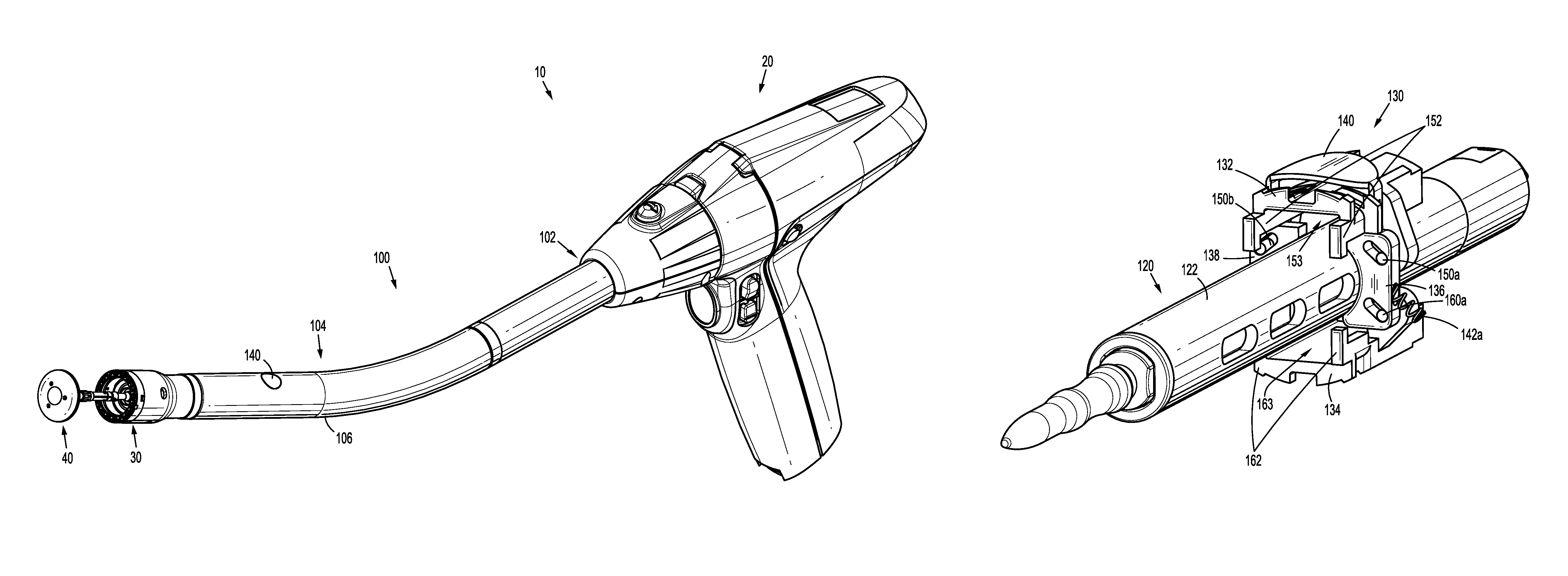
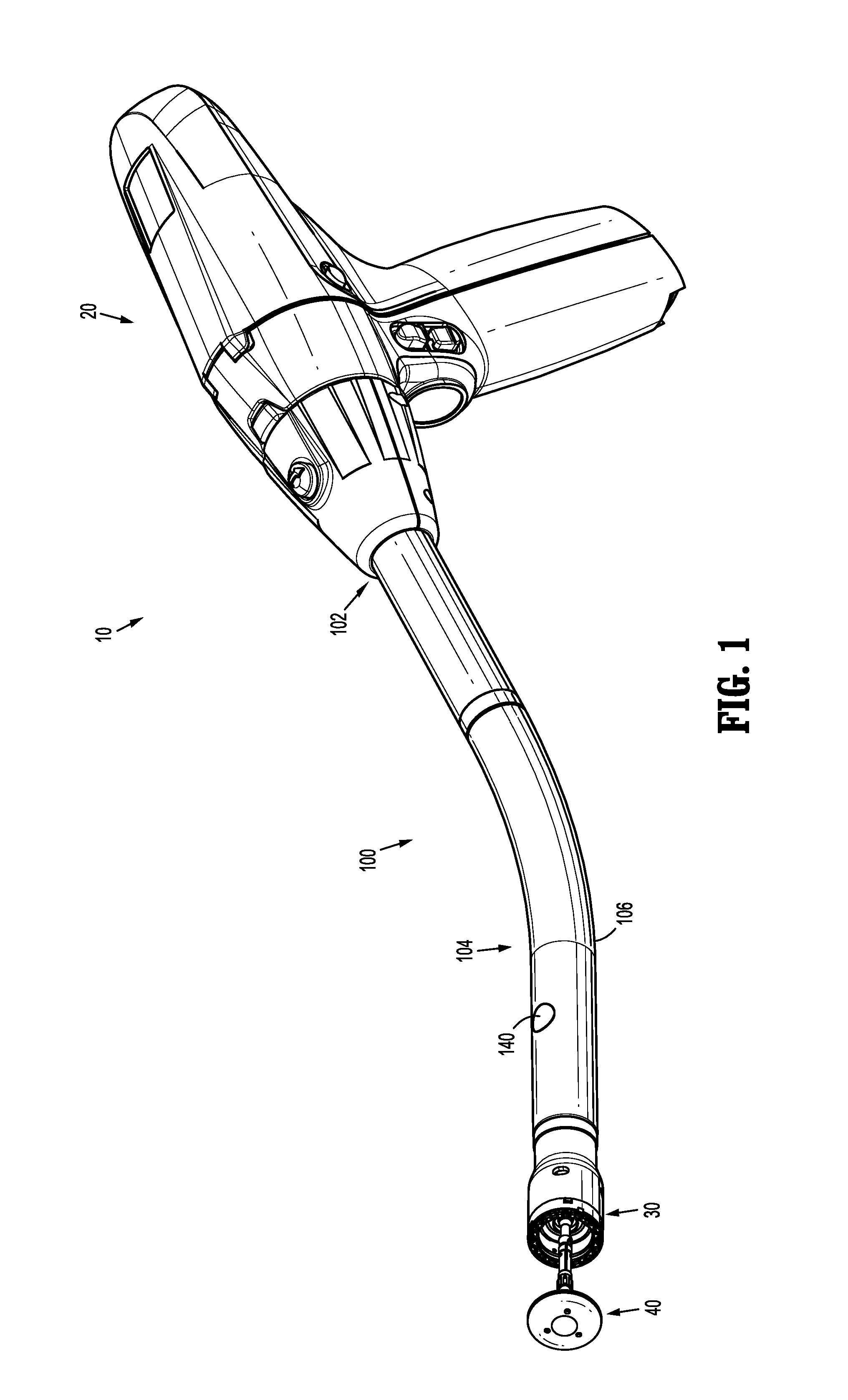
FIG. 1 is a perspective view of a surgical stapling device including an handle assembly with an adapter assembly according to one embodiment of the present disclosure;
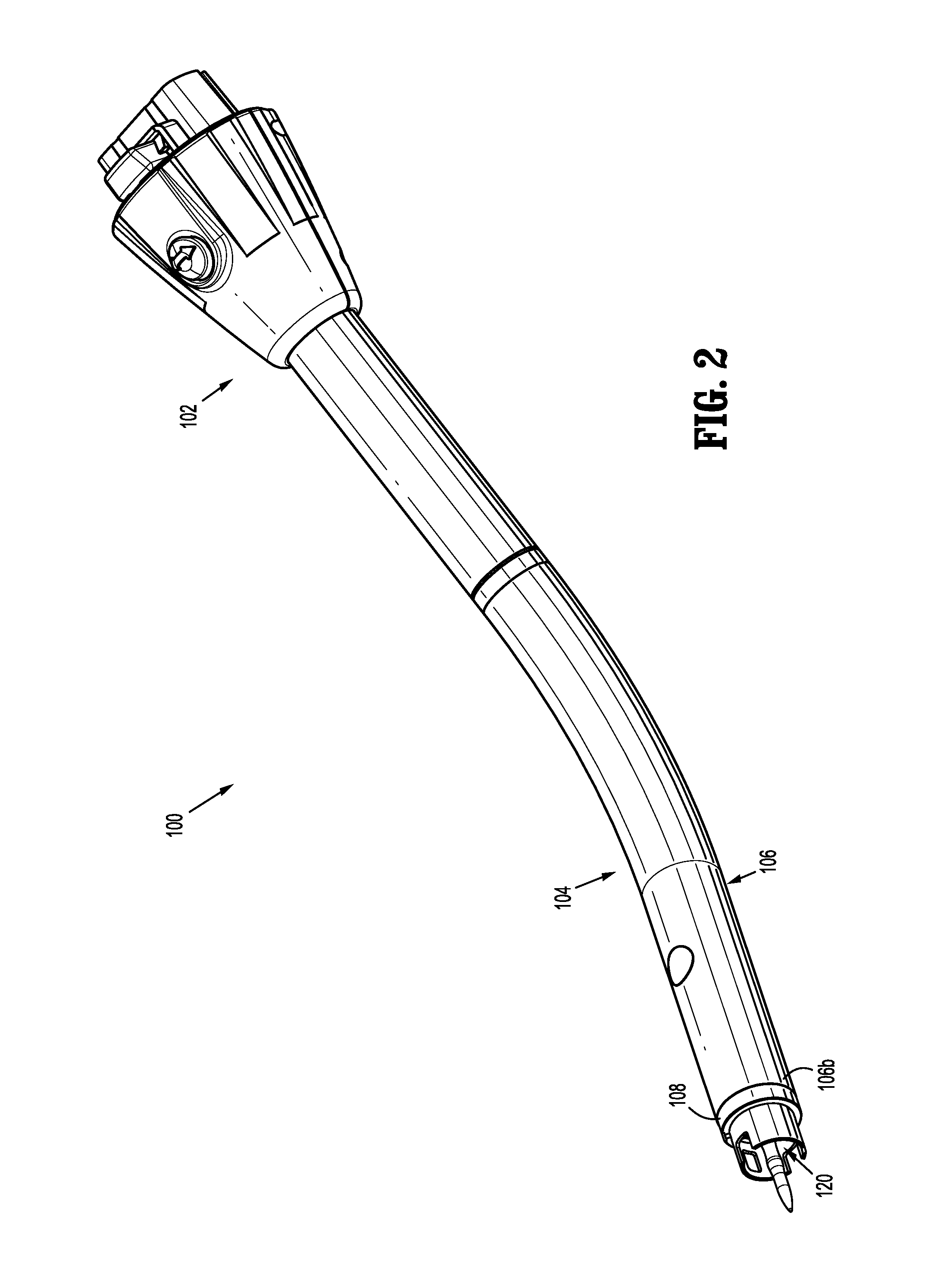
FIG. 2 is a perspective view of the adapter assembly shown in FIG. 1 with a removable trocar assembly extending from a distal end of the adapter assembly;
FIG. 3 is a perspective view of a drive assembly of the adapter assembly shown in FIG. 1 with components separated;
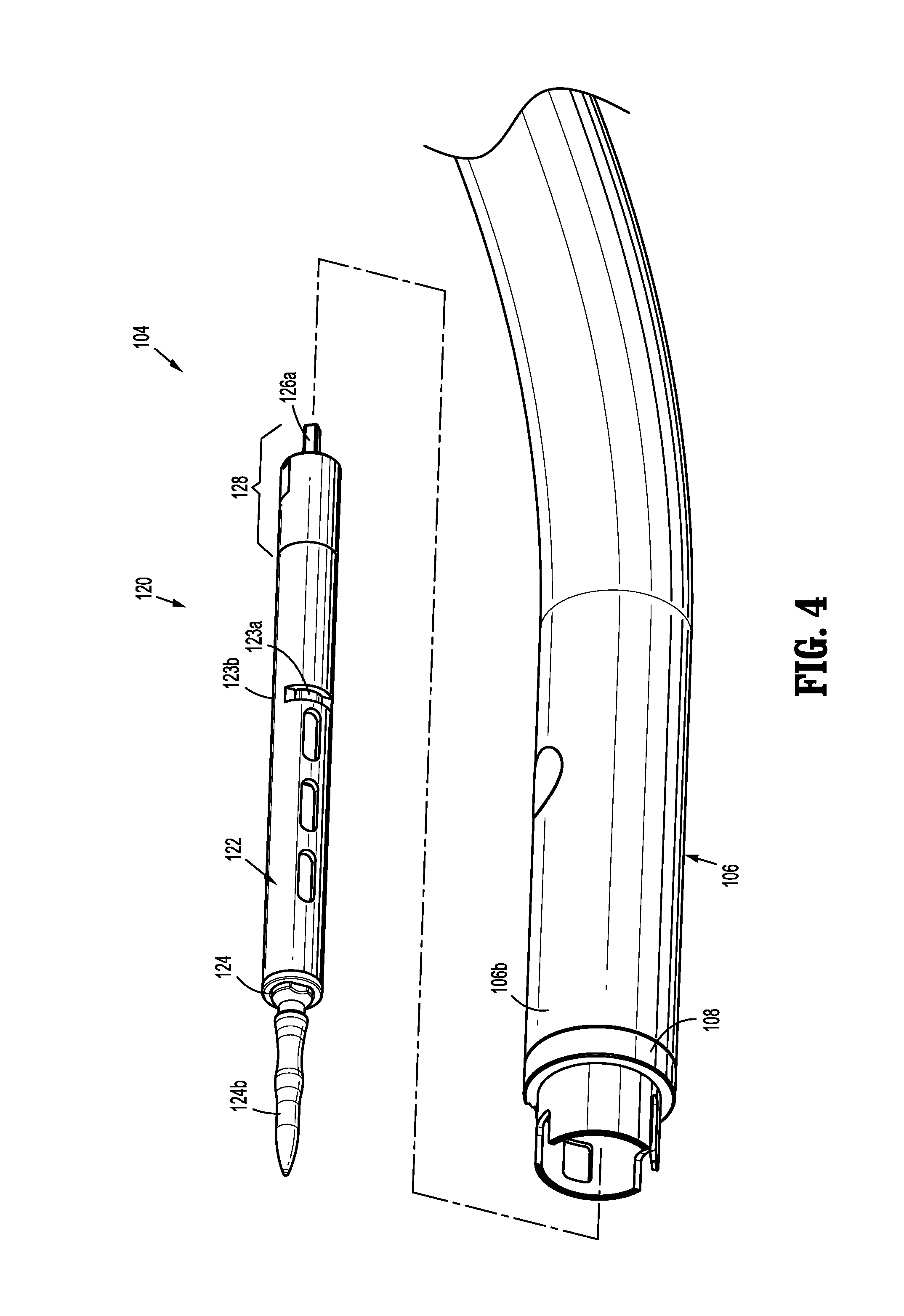
FIG. 4 is a side perspective view of the removable trocar assembly, a sleeve, and a connector housing of the adapter assembly shown in FIG. 1, with components separated;
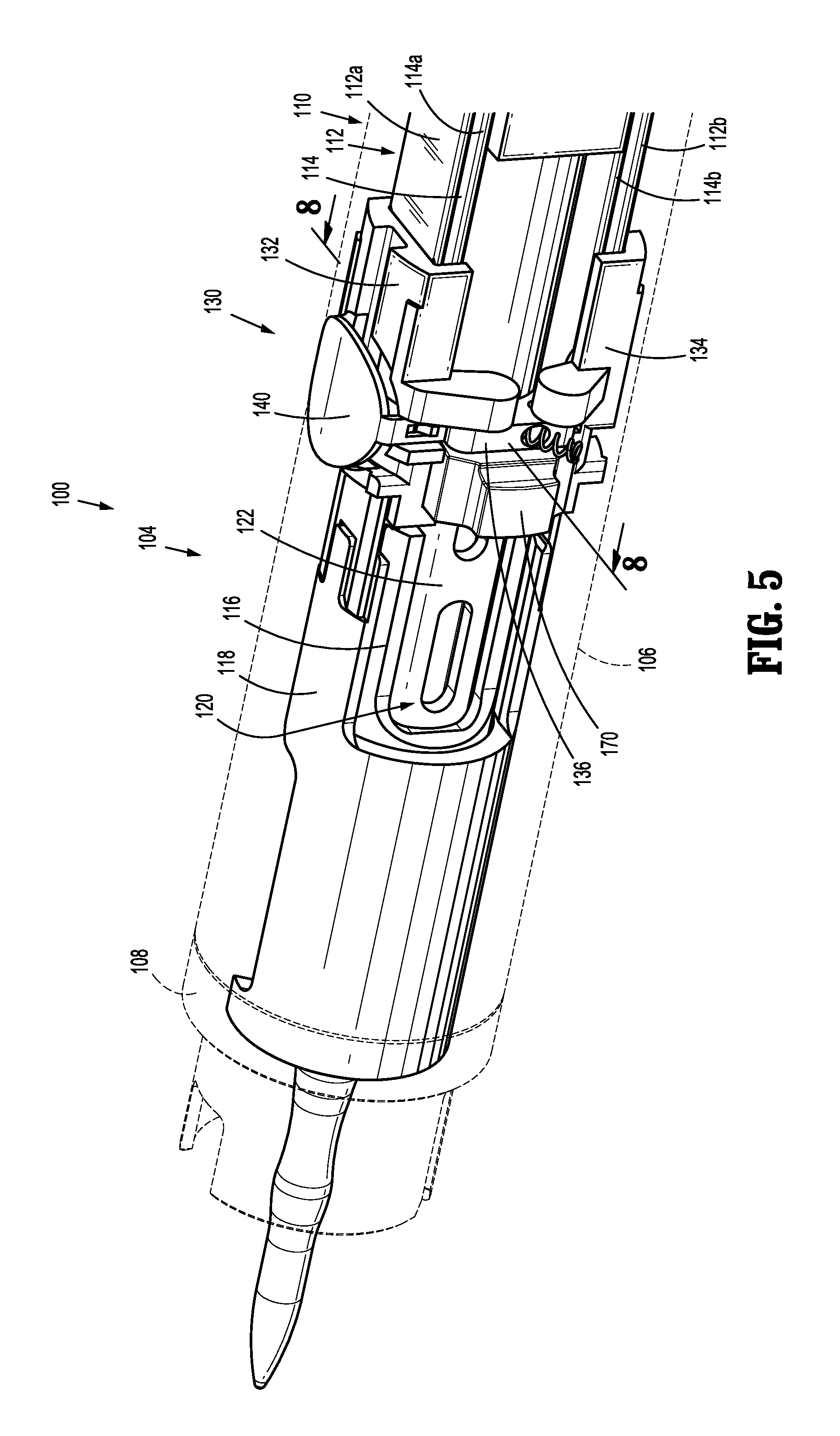
FIG. 5 is a side perspective view of a distal end of the adapter assembly shown in FIG. 1, with the sleeve shown in phantom;
FIG. 6 is a perspective view of the removable trocar assembly shown in FIG. 4, with parts separated;
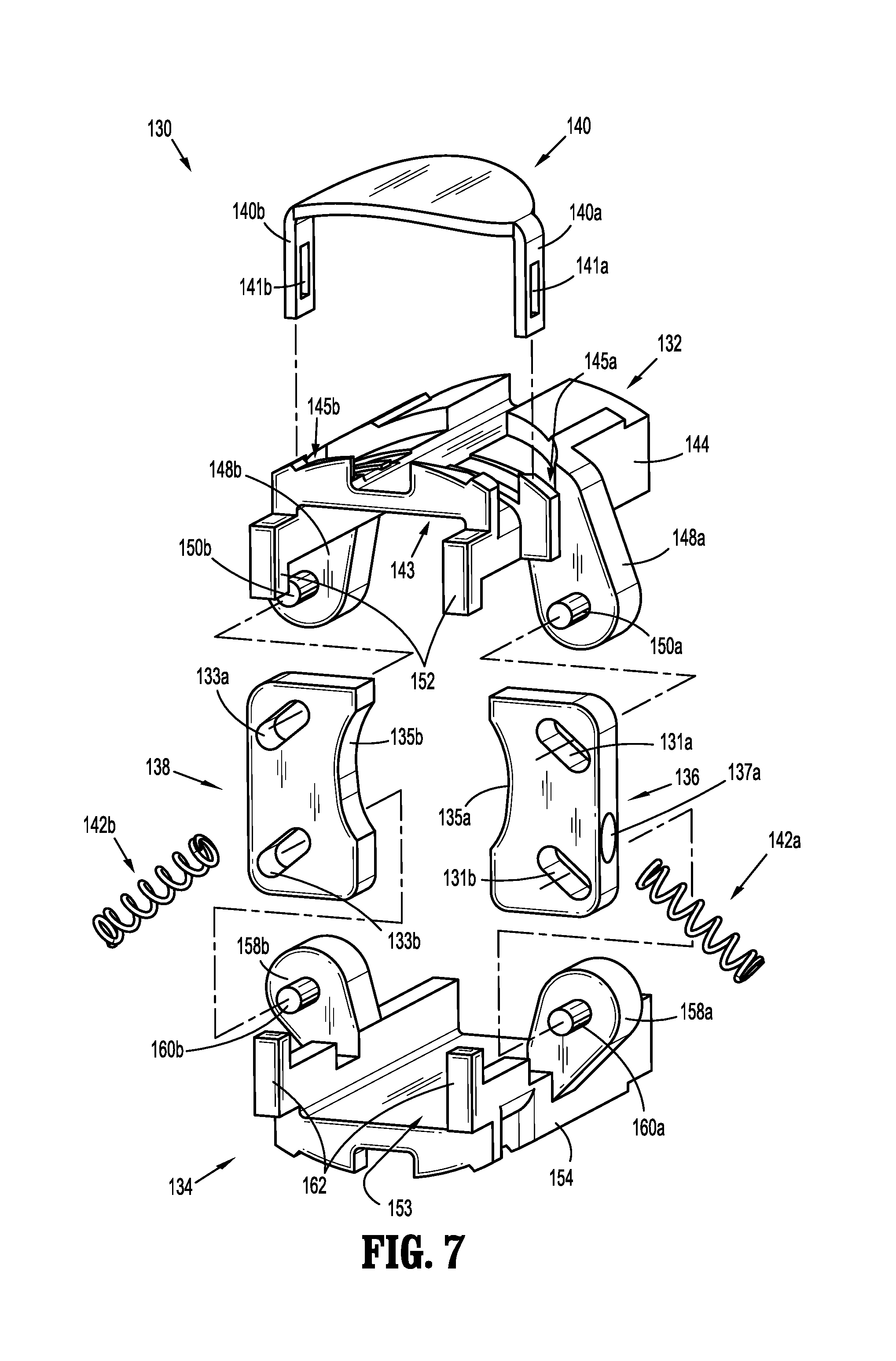
FIG. 7 is a side perspective view of a locking mechanism of the adapter assembly shown in FIG. 1, with parts separated;
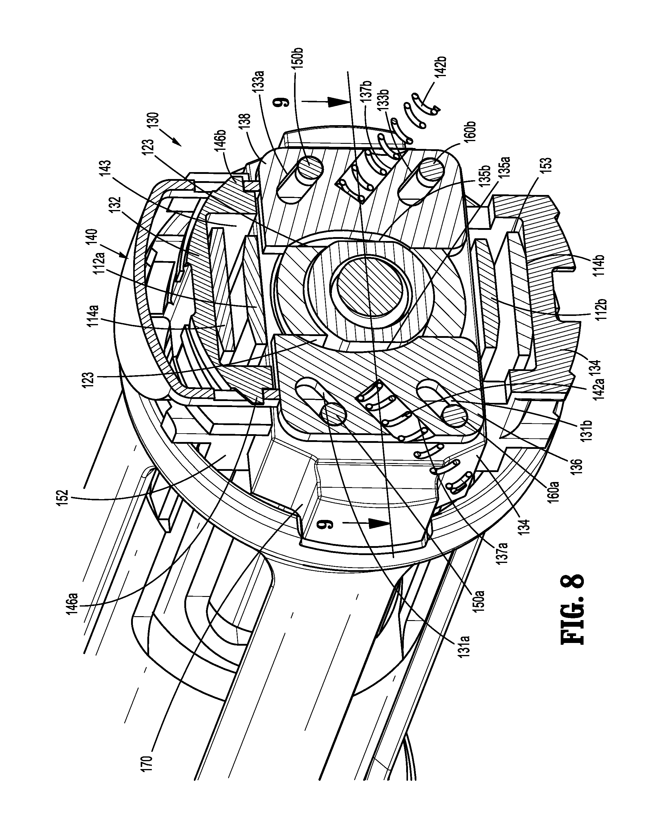
FIG. 8 is a cross-sectional perspective view taken along section line 8-8 shown in FIG. 5;
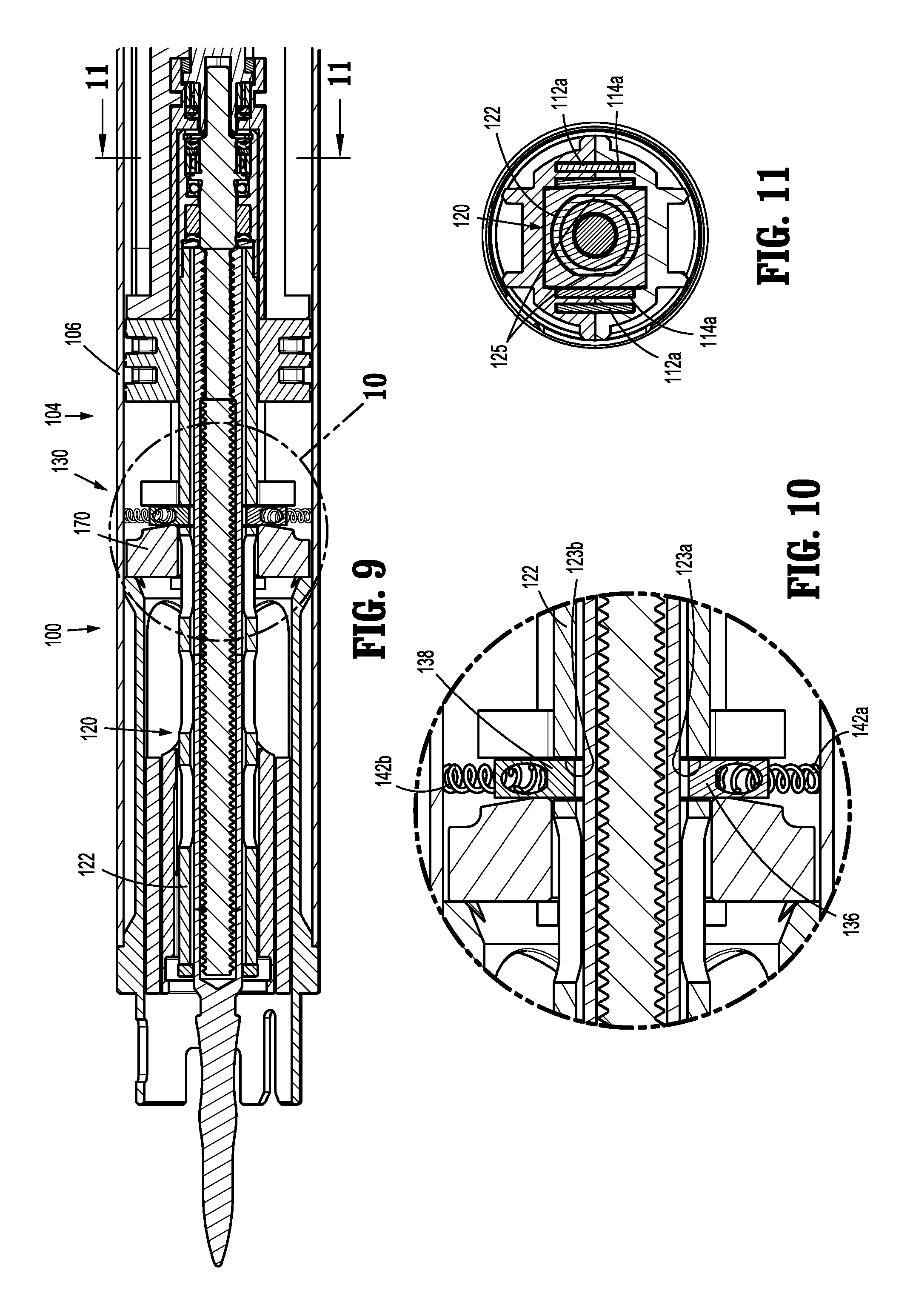
FIG. 9 is a cross-sectional top view taken along section line 9-9 shown in FIG. 8, with first and second locking blocks of the locking mechanism in a locked position;
FIG. 10 is an enlarged view of the indicated area of detail shown in FIG. 9;
FIG. 11 is a cross-sectional end view taken along section line 11-11 shown in FIG. 9;
FIG. 12 is a cross-sectional view taken along section lines 8-8 shown in FIG. 5, with the locking mechanism in a first or locked position;
FIG. 13 is a perspective side view of the removable trocar assembly and the locking mechanism of the adapter assembly shown in FIG. 1, in the locked position;
FIG. 14 is a cross-sectional view taken along respective section lines 8-8 shown in FIG. 5, with the locking mechanism in a second or release position;
FIG. 15 is a perspective side view of the removable trocar assembly and the locking mechanism shown in FIG. 13, in the release position; and
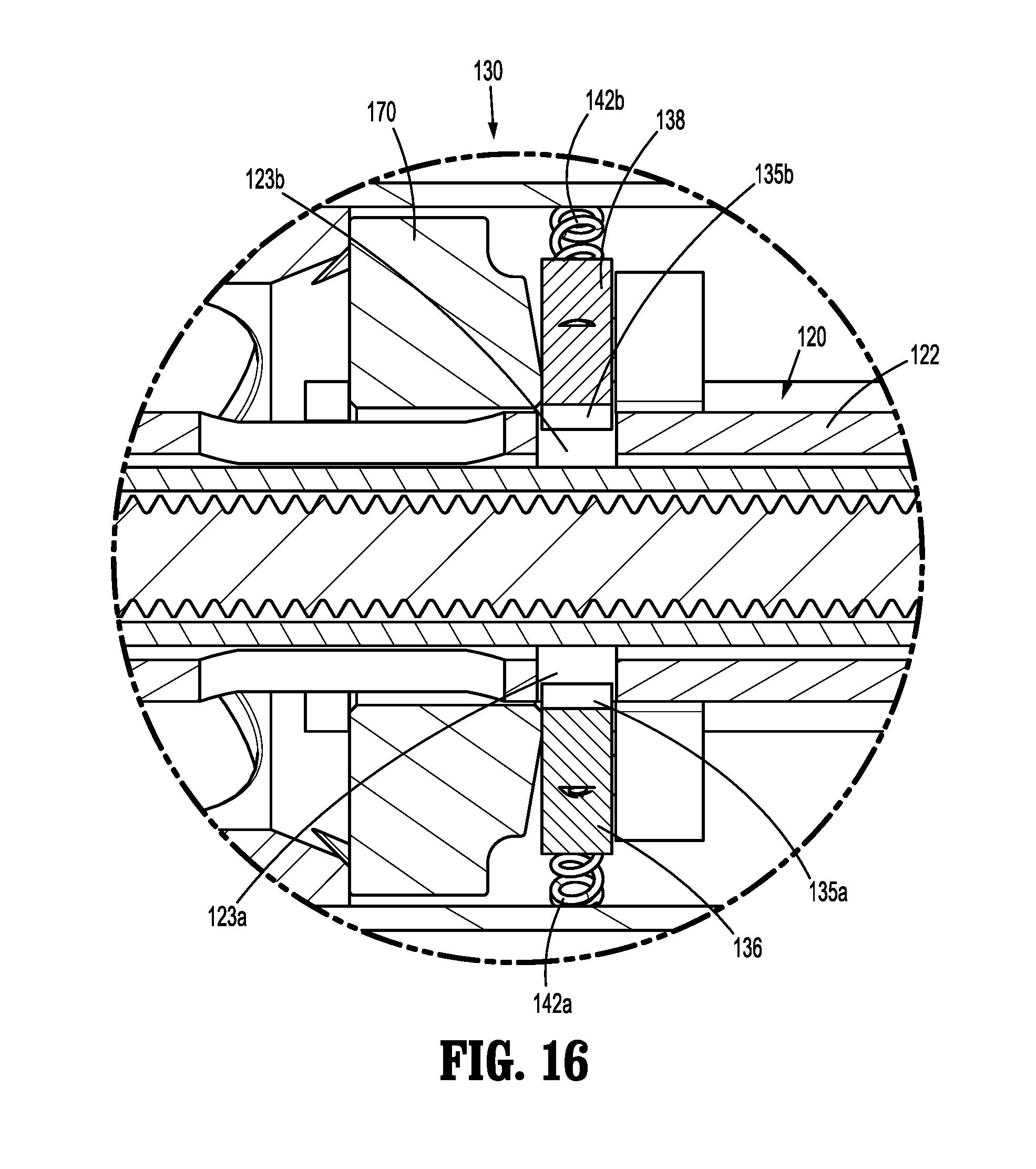
FIG. 16 is a cross-sectional top view taken along section line 9-9 shown in FIG. 8, with first and second locking blocks of the locking mechanism in an unlocked position.
DETAILED DESCRIPTION
Embodiments of the presently disclosed adapter assembly including a removable trocar assembly will now be described in detail with reference to the drawings in which like reference numerals designate identical or corresponding elements in each of the several views. As is common in the art, the term "proximal" refers to that part or component closer to the user or operator, i.e. surgeon or clinician, while the term "distal" refers to that part or component further away from the user.
Referring initially to FIG. 1, an adapter assembly according to an embodiment of the present disclosure, shown generally as adapter assembly 100, is a component of a surgical stapling device 10. The surgical stapling device 10 further includes a powered handle assembly 20, a loading unit 30, and an anvil assembly 40. Although shown and described with reference to surgical stapling device 10, the aspects of the present disclosure may be modified for use with manual surgical stapling devices having various configurations, and with powered surgical stapling devices having alternative configurations. For a detailed description of an exemplary surgical stapling device, please refer to commonly owned U.S. Pat. No. 9,023,014 ("the '014 patent) and U.S. Pat. Appl. Publ. No. 2012/0253329 ("the '329 application"), the contents of each of which are incorporated by reference herein in their entirety.
With reference to FIG. 2, the adapter assembly 100 includes a proximal portion 102 configured for operable connection to the handle assembly 20 (FIG. 1) and a distal portion 104 configured for operable connection to the loading unit 30 (FIG. 1) and to the anvil assembly 40 (FIG. 1). Although shown and described as forming an integral unit, it is envisioned that the proximal and distal portions 102, 104 may be formed as separate units that are releasably securable to one another.
The adapter assembly 100 will only be described to the extent necessary to fully disclose the aspects of the present disclosure. For a detailed description of an exemplary adapter assembly, please refer to commonly owned U.S. Provisional Pat. Appl. Ser. No. 62/066,518 ("the '518 application"), the content of which is incorporated by reference herein in its entirety.
With continued reference to FIG. 2, the adapter assembly 100 includes an outer sleeve 106, and a connector housing 108 secured to a distal end of the outer sleeve 106. The connector housing 108 is configured to releasably secure an end effector, e.g., the end effector 30 (FIG. 1), to the adapter assembly 100.
Turning briefly to FIG. 3, a drive assembly 110 extends through the outer sleeve 106 (FIG. 2) of the adapter assembly 100, and includes an inner flexible band assembly 112 and an outer flexible band assembly 114. The inner flexible band assembly 112 includes first and second flexible bands 112a, 112b, and an inner pusher member 116 connected to the distal ends of the first and second flexible bands 112a, 112b. Similarly, the outer flexible band assembly 114 includes first and second flexible bands 114a, 114b, and an outer pusher member 118. For a detailed description of the structure and function of the drive assembly 110, please refer to the '518 application, the content of which was previously incorporated herein by reference in its entirety.
With reference now to FIGS. 4 and 5, the adapter assembly 100 further includes a trocar assembly 120 that extends through the actuation assembly 110 (FIG. 5), and a locking mechanism 130 (FIG. 5) that releasably secures the trocar assembly 120 relative to the outer sleeve 106 of the adapter assembly 100. The trocar assembly 120 will only be described to the extent necessary to describe the aspects of the present disclosure. For a detail description of the structure and function of an exemplary trocar assembly, please refer to the '518 application, the content of which was previously incorporated by reference herein in its entirety.
Referring also to FIG. 6, the trocar assembly 120 of the adapter assembly 100 (FIG. 2) includes an outer housing 122, a trocar member 124 slidably disposed within the outer housing 122, and a drive screw 126 operably received within the trocar member 124 for axially moving the trocar member 124 relative to the outer housing 122. More specifically, the trocar member 124 defines a threaded bore 124a which is dimensioned to receive the drive screw 126. The outer-surface of the drive screw 126 is threaded such that rotation of the drive screw 126 causes longitudinal movement of the trocar member 124 within the outer housing 122 of the trocar assembly 120. A distal end 124b of trocar member 124 is configured to releasably engage an anvil assembly, e.g., the anvil assembly 40 (FIG. 1). A bearing assembly 128 is mounted to a proximal end of outer housing 122 of trocar assembly 120 for rotatably supporting the drive screw 126 within the outer housing 122 and the trocar member 124. As will be described in further detail below, the outer housing 122 defines first and second locking slots 123a, 123b for receiving the respective first and second locking blocks 136, 138 (FIG. 7) of the locking mechanism 130 of the adapter assembly 100.
With particular reference now to FIG. 7, the locking mechanism 130 of the adapter assembly 100 includes upper and lower band guides 132, 134 supported within the outer sleeve 106 (FIG. 5), first and second locking blocks 136, 138 operably supported on each of the upper and lower band guides 132, 134, and a button member 140 slidably secured to the upper band guide 132 for moving the first and second locking blocks 136, 138 relative to each other. As will be described in further detail below, first and second springs 142a, 142b extend from within respective first and second locking blocks 136, 138 and bias the locking blocks 136, 138 radially inward.
With continued reference to FIG. 7, the upper band guide 132 of the locking mechanism 130 includes a body portion 144 disposed within the outer sleeve 106 of the adapter assembly 100. The body portion 144 of the upper band guide 132 defines a longitudinal recess 143 for accommodating the first flexible bands 112a, 114a of the respective inner and outer flexible band assemblies 112, 114. The body portion 144 of the upper band guide 132 further defines first and second cutouts 145a, 145b for operably receiving respective first and second legs 140a, 140b of the button member 140 of the locking mechanism 130. First and second button retainer tabs 146a, 146b (FIG. 12) extend outwardly from the body portion 144 of the upper band guide 132. In particular, the first button retainer tab 146a is disposed in the first cutout 145a of the body portion 144 and the second button retainer tab 146b is disposed in the second cutout 145b of the body portion 144.
As will be described in further detail below, the first and second button retainer tabs 146a, 146b are received within respective slots 141a, 141b of the button member 140 to operably secure the button member 140 to the upper guide band 132. First and second flange portions 148a, 148b extend outwardly from the body portion 144 of the upper band guide 132. Each of the first and second flange portions 148a, 148b includes a cam post 150a, 150b, respectively. As will be described in further detail below, the cam posts 150a, 150b of the respective first and second flange portions 148a, 148b are received within first and second cam slots 131a, 131b and 133a, 133b of first and second locking blocks 136, 138. The upper band guide 132 further includes strain gauge retainer portions 152 extending from the body portion 144 for supporting a strain gauge 170 (FIG. 8).
With continued reference to FIG. 7, the lower band guide 134 of the locking mechanism 130 includes a body portion 154 disposed within the outer sleeve 106 (FIG. 1) of the adapter assembly 100. The body portion 154 of the lower band guide 134 defines a longitudinal recess 153 for accommodating the second inner and outer flexible bands 112b, 114b (FIG. 3) of the respective inner and outer flexible band assemblies 112, 114 (FIG. 3). The lower band guide 134 includes first and second flange portions 158a, 158b that extend outwardly from the body portion 154. The first and second flange portions 158a, 158b include first and second cam posts 160a, 160b, respectively. The lower band guide 134 further includes strain gauge retainer portions 162 extending from the body portion 144 configured to operate with the strain gauge retainer portions 152 of the upper band guide 132 to support the strain gauge 170 (FIG. 8) about the trocar assembly 120.
As will be described in further detail below, the upper and lower band guides 132, 134 of the locking mechanism 130 are configured such that the first cam posts 150a, 160a of the respective upper and lower band guides 132, 134 are received within first cam slots 131a, 131b of the first locking block 136 and the second cam posts 150b, 160b of the respective upper and lower band guides 132, 134 are received within the second cam slots 133a, 133b of the second locking block 138. With additional reference to FIG. 8, the first and second locking blocks 136, 138 of the locking mechanism 130 are movably supported on the upper and lower band guides 132, 134 and are configured to be releasably received within the respective first and second locking slots 123a, 123b (FIG. 6) of the trocar housing 122 of the trocar assembly 120.
Each of the first and second locking blocks 136, 138 defines a clearance portions 135a, 135b, respectively, to facilitate disengagement of the respective first and second locking blocks 136, 138 from the trocar assembly 120. In particular, the clearance portions 135a, 135b are configured such that when the first and second locking blocks 136, 138 are in their second positions (FIGS. 14 and 15), the first and second locking blocks 136, 138 are clear of the outer housing 122 of the trocar assembly 120. As shown in FIG. 14, the clearance portions 135a, 135b of the respective first and second locking blocks 136, 138 together define a substantially circular opening with the first and second locking blocks 136, 138 are in their second position. Each of the first and second locking blocks 136, 138 further defines a bore 137a, 137b (FIG. 8), respectively, for receiving the first and second springs 142a, 142b.
The first and second locking blocks 136, 138 of the locking mechanism 130 are movable between a first, locked position (FIG. 12) in which the outer housing 122 of the trocar assembly 120 is engaged by the first and second locking blocks 136, 138, i.e., portions of the first and second locking blocks 136, 138 are received within respective locking slots 123a, 123b of the outer housing 122, and a second, unlocked position (FIG. 14) in which the trocar assembly 120 is moved outwardly from slots 123a, 123b such that is removable from between the first and second locking blocks 136, 138 of the locking mechanism 130, i.e., the clearance portions 135a, 135b of the respective first and second blocks 136, 138 are aligned with the outer housing 122. The first and second locking blocks 136, 138 are biased inwardly into slots 123a, 123b to the first position by the first and second springs 142a, 142b. As shown in FIG. 8, the first and second locking blocks 136, 138 are biased upwardly and inwardly towards one another.
With particular reference still to FIG. 7, the button member 140 of the locking mechanism 130 includes first and second legs 140a, 140b each defining a slot 141a, 141b, respectively. The button member 140 is configured to be received about the upper band guide 132 of the locking mechanism 130 such that the first and second legs 140a, 140b of the button member 140 are received within respective first and second cutouts 145a, 145b of the upper band guide 132 and the first and second tabs 146a, 146b (FIG. 8) of the upper band guide 134 are received within the respective slots 141a, 141b.
The operation of the locking mechanism 130 of the adapter assembly 100 will now be described with reference to FIGS. 8-16. Referring initially to FIGS. 8-13, the locking mechanism 130 is shown in the locked configuration, i.e., with the first and second locking blocks 136, 138 in their first position. In particular, the first locking block 136 is supported on the first cam post 150a of the upper band guide 132 and the first cam post 160b of the lower band guide 134 and the second locking block 138 is supported on the second cam post 150b of the upper band guide 132 and the second cam post 160b of the lower band guide 134. The first and second locking blocks 136, 138 are biased radially inward by respective first and second springs 142a, 142b to the first, locked position (FIG. 12).
The trocar assembly 120 of adapter assembly 100 may be provided preloaded within sleeve 106 of the adapter assembly 100, or the trocar assembly 120 may be provided separated from the adapter assembly 100. If provided as a separate component, the trocar assembly 120 is loaded through a distal end of the sleeve 106 of the adapter assembly 100 prior to attaching an end effector, e.g., the end effector 30, to the connector housing 108 of the adapter assembly 100. The trocar assembly 120 is fed into the sleeve 106 of the adapter assembly 100 between the first and second locking blocks 136, 138 to cam the first and second locking blocks 136, 138 outwardly against the bias of springs 142a, 142b until alignment of the first and second locking blocks 136, 138 with the first and second locking slots 123a, 123b of the outer housing 122. An audible and/or tactile indication may be provided to a user by the locking mechanism 130 as the first and second locking blocks 136, 138 are received with the respective first and second locking slots 123a, 123b to indicate that the trocar assembly 120 is securely received within the locking mechanism 130.
During loading of the trocar assembly 120 through the locking mechanism 130, the button member 140 of the locking mechanism 130 may be depressed to move the first and second locking blocks to the second or unlocked position (FIG. 14) to facilitate loading of the trocar assembly 120 between the first and second locking blocks 136, 138, and within the sleeve 106. Alternatively, engagement of the first and second locking blocks 136, 138 by the outer housing 122 of the trocar assembly 120 as the trocar assembly 120 is loaded through the locking mechanism 130 will maintain the first and second locking blocks 136, 138 in their second position until the first and second locking slots 123a, 123b of the outer housing 122 align with the respective first and second locking blocks 136, 138. Upon alignment of the first and second locking blocks 136, 138 with the respective first and second locking slots 123a, 123b, the first and second locking blocks 136, 138 are biased into the first and second locking slots 123a, 123b, respectively.
In embodiments, the outer housing 122 of the trocar assembly 120 includes internal flat portions 125 (FIG. 11) for maintaining rotational alignment of the trocar assembly 120 relative to the locking mechanism 130 to ensure that the first and second locking slots 123a, 123b of the trocar assembly 120 are maintained in alignment with the respective first and second locking blocks 136, 138 of the locking mechanism 130.
Engagement of the first and second legs 140a, 140b of the button member 140 of the locking mechanism 130 with the respective first and second locking blocks 136, 138 maintains the button member 140 in an outward, non-depressed position. Receipt of the first and second button retainer tabs 146a, 146b within respective slots 141a, 141b of the first and second leg 140a, 140, respectively, of button member 140 maintains the button member 140 in engagement with the upper band guide 132 of the locking mechanism 130.
As noted above, the upper and lower band guides 132, 134 each include strain gauge retainer portions 152, 162, respectively, for supporting the strain gauge 170. The trocar assembly 120 of the adapter assembly 100 is received through the strain gauge 170. The strain gauge 170 is configured to measure deflection and/or movement of the trocar assembly 120 during operation of the adapter assembly 100. The first and second flexible bands 112a, 114a of the inner and outer flexible band assemblies 112, 114 of the drive assembly 110 are received through the longitudinal recess 143 of the upper band guide 132 and the first and second flexible bands 112a, 114b of the inner and outer flexible band assemblies 112, 114 are received through the longitudinal recess 153 of the lower band guide 134.
Once the trocar assembly 120 is loaded with the sleeve 106 and secured therein by the locking mechanism 130, the adapter assembly 100 and the attached handle assembly 20 (FIG. 1), the loading unit 30, and the anvil assembly 40 (FIG. 1) operate in a traditional manner.
Following a surgical stapling procedure using the surgical stapling device 10, the trocar assembly 120 of the adapter assembly 100 is removed from the sleeve 106 of the adapter assembly 100 to facilitate cleaning and/or sterilizing of the adapter assembly 100.
With reference to FIGS. 14-16, the locking mechanism 130 of the adapter assembly 100 is shown with the first and second locking blocks 136, 138 in a second or unlocked position. When the first and second locking blocks 136, 138 are in the second position, the trocar assembly 120 is removable from within the sleeve 106 of the adapter assembly 100.
With particular reference to FIG. 14, the first and second locking blocks 136, 138 are moved to the second position by depressing the button member 140 of the locking mechanism 130 radially inward, as indicated by arrow "A" in FIG. 14. As noted above, the first and second leg portions 140a, 140b of the button member 140 engage an upper surface of the respective first and second locking blocks 136, 138. When the button member 140 is depressed, engagement between the first and second leg portions 140a, 140b of the button member 140 with the respective first and second locking blocks 136, 138 moves the first and second locking blocks 136, 138 downwardly about the cam posts 150a, 160a and 150b, 160b against the bias of the first and second springs 142a, 142b, respectively. The first locking block 136 rides along the first cam post 150a, 160a of the upper and lower band guide 132, 134, respectively. Because of the configuration of the cam slots 131a, 131b, the first locking block 136 moves in a radially outward direction, as indicated by arrow "B" to the second position. Similarly, the second locking block 138 rides along the second cam post 150b, 160b of the upper and lower band guide 132, 134, respectively. Because of the configuration of the cam slots 133a, 133b, the second locking block 138 moves in a radially outward direction, as indicated by arrow "C", to the second position.
As the first and second locking blocks 136, 138 are moved to their second position, the first and second locking blocks 136, 138 are moved from within the respective first and second locking slots 123a, 123b of the trocar assembly 120 and the clearance portions 135a, 135b of the respective first and second locking blocks 136, 138 are aligned with the trocar assembly 120. In this manner, the trocar assembly 120 is no longer secured by the locking mechanism 130. The trocar assembly 120 may then be removed from within the sleeve 106 of the adapter assembly 100.
Although the illustrative embodiments of the present disclosure have been described herein with reference to the accompanying drawings, it is to be understood that the disclosure is not limited to those precise embodiments, and that various other changes and modifications may be effected therein by one skilled in the art without departing from the scope or spirit of the disclosure. For example, in any of the embodiments discussed herein, the trocar assembly may form part of a circular surgical stapler that is wholly or partially disposable and such instruments may have a separate adapter or the adapter may be formed as part of the handle assembly. The stapling instrument can be manually operated, powered through an integral or separate motor, or form part of a robotic system.
* * * * *
D00000
D00001
D00002
D00003
D00004
D00005
D00006
D00007
D00008
D00009
D00010
D00011
D00012
XML
uspto.report is an independent third-party trademark research tool that is not affiliated, endorsed, or sponsored by the United States Patent and Trademark Office (USPTO) or any other governmental organization. The information provided by uspto.report is based on publicly available data at the time of writing and is intended for informational purposes only.
While we strive to provide accurate and up-to-date information, we do not guarantee the accuracy, completeness, reliability, or suitability of the information displayed on this site. The use of this site is at your own risk. Any reliance you place on such information is therefore strictly at your own risk.
All official trademark data, including owner information, should be verified by visiting the official USPTO website at www.uspto.gov. This site is not intended to replace professional legal advice and should not be used as a substitute for consulting with a legal professional who is knowledgeable about trademark law.