Pressure regulator
Young , et al. Dec
U.S. patent number 10,503,181 [Application Number 14/994,989] was granted by the patent office on 2019-12-10 for pressure regulator. This patent grant is currently assigned to Honeywell International Inc.. The grantee listed for this patent is Honeywell International Inc.. Invention is credited to Donald J. Kasprzyk, David Kucera, Jos Praat, Gregory Young.


View All Diagrams
| United States Patent | 10,503,181 |
| Young , et al. | December 10, 2019 |
Pressure regulator
Abstract
The disclosure relates generally to pressure regulators, and more particularly, to pressure regulating valves. In one illustrative but non-limiting example, a pressure in a flow channel is translated into a position of a diaphragm, wherein the position of the diaphragm is dependent on the pressure in the flow channel. The position of the diaphragm is then sensed. A position of a valve in the flow channel is then controlled to adjust the pressure in the flow channel acting on the diaphragm so that the sensed position of the diaphragm is driven toward a predetermined position. This may result in regulated pressure in the fluid channel.
| Inventors: | Young; Gregory (Blaine, MN), Kucera; David (Bilovice nad Svitavou, CZ), Praat; Jos (Borger, NL), Kasprzyk; Donald J. (Maple Grove, MN) | ||||||||||
|---|---|---|---|---|---|---|---|---|---|---|---|
| Applicant: |
|
||||||||||
| Assignee: | Honeywell International Inc.
(Morris Plains, NJ) |
||||||||||
| Family ID: | 59275703 | ||||||||||
| Appl. No.: | 14/994,989 | ||||||||||
| Filed: | January 13, 2016 |
Prior Publication Data
| Document Identifier | Publication Date | |
|---|---|---|
| US 20170199530 A1 | Jul 13, 2017 | |
| Current U.S. Class: | 1/1 |
| Current CPC Class: | G05D 16/2095 (20190101); G05D 16/2013 (20130101) |
| Current International Class: | G05D 16/20 (20060101) |
| Field of Search: | ;73/1.57-1.72,861.47,861.48,715-729.1 |
References Cited [Referenced By]
U.S. Patent Documents
| 156769 | November 1874 | Cameron |
| 424581 | April 1890 | Sickels |
| 1033204 | July 1912 | Skinner |
| 1147840 | July 1915 | Bowser |
| 1156977 | October 1915 | Cloos |
| 1165315 | December 1915 | Cameron |
| 1206532 | November 1916 | Gray |
| 1847385 | March 1932 | Dengler |
| 2196798 | April 1940 | Horstmann |
| 2403692 | July 1946 | Tibbetts |
| 2791238 | May 1957 | Bryant |
| 2975307 | March 1961 | Schroeder et al. |
| 3164364 | January 1965 | McColl |
| 3202170 | August 1965 | Holbrook |
| 3239827 | March 1966 | Werner |
| 3304406 | February 1967 | King |
| 3346008 | October 1967 | Scaramucci |
| 3381623 | May 1968 | Elliott |
| 3414010 | December 1968 | Sparrow |
| 3444736 | May 1969 | Stedman |
| 3498130 | March 1970 | Brown |
| 3641373 | February 1972 | Elkuch |
| 3646969 | March 1972 | Stampfli |
| 3744754 | July 1973 | Demi |
| 3747406 | July 1973 | Maurer |
| 3769531 | October 1973 | Elkuch |
| 3803424 | April 1974 | Smiley et al. |
| 3884266 | May 1975 | Kondo |
| 3947644 | March 1976 | Uchikawa |
| 3960364 | June 1976 | Hargrave |
| 3973576 | August 1976 | Dietiker |
| 3973976 | August 1976 | Boyd |
| 3993939 | November 1976 | Slavin et al. |
| 4114652 | September 1978 | Oberle |
| 4115036 | September 1978 | Paterson |
| 4140936 | February 1979 | Bullock |
| 4188013 | February 1980 | Battersby et al. |
| 4188972 | February 1980 | Van Der Zee |
| 4197737 | April 1980 | Pittman |
| 4242080 | December 1980 | Tabei |
| 4277832 | July 1981 | Wong |
| 4360955 | November 1982 | Block |
| 4402340 | September 1983 | Lockwood, Jr. |
| 4406131 | September 1983 | Weasel, Jr. |
| 4406400 | September 1983 | Berkhof |
| 4418886 | December 1983 | Holzer |
| 4442853 | April 1984 | Gort |
| 4450868 | May 1984 | Duval et al. |
| 4453169 | June 1984 | Martner |
| 4478076 | October 1984 | Bohrer |
| 4478077 | October 1984 | Bohrer et al. |
| 4481776 | November 1984 | Araki et al. |
| 4491149 | January 1985 | Trinkwalder |
| 4493303 | January 1985 | Thompson et al. |
| 4498850 | February 1985 | Perlov et al. |
| 4501144 | February 1985 | Higashi et al. |
| 4539575 | September 1985 | Nilsson |
| 4543974 | October 1985 | Dietiker et al. |
| 4576050 | March 1986 | Lambert |
| 4581624 | April 1986 | O'Connor |
| 4581707 | April 1986 | Millar |
| 4585209 | April 1986 | Aine et al. |
| 4619438 | October 1986 | Coffee |
| 4622699 | November 1986 | Spriggs |
| 4622999 | November 1986 | Ray |
| 4645450 | February 1987 | West |
| 4651564 | March 1987 | Johnson et al. |
| 4654546 | March 1987 | Kirjavainen |
| 4705065 | November 1987 | McNeely |
| 4722360 | February 1988 | Odajima et al. |
| 4756508 | July 1988 | Giachino et al. |
| 4785846 | November 1988 | Kragten |
| 4815699 | March 1989 | Mueller |
| 4821999 | April 1989 | Ohtaka |
| 4829826 | May 1989 | Valentin et al. |
| 4835717 | May 1989 | Michel et al. |
| 4836247 | June 1989 | Chuang |
| 4898200 | February 1990 | Odajima et al. |
| 4911616 | March 1990 | Laumann, Jr. |
| 4915613 | April 1990 | Landis |
| 4938742 | July 1990 | Smits |
| 4939405 | July 1990 | Okuyama et al. |
| 5022435 | June 1991 | Jaw-Shiunn |
| 5065978 | November 1991 | Albarda et al. |
| 5069419 | December 1991 | Jerman |
| 5070252 | December 1991 | Castenschiold et al. |
| 5078581 | January 1992 | Blum et al. |
| 5082242 | January 1992 | Bonne et al. |
| 5082246 | January 1992 | Stanley et al. |
| 5085562 | February 1992 | Van Lintel |
| 5096388 | March 1992 | Weinberg |
| 5129794 | July 1992 | Beatty |
| 5146941 | September 1992 | Statler |
| 5148074 | September 1992 | Fujita et al. |
| 5171132 | December 1992 | Miyazaki et al. |
| 5176358 | January 1993 | Bonne et al. |
| 5180288 | January 1993 | Richter et al. |
| 5180623 | January 1993 | Ohnstein |
| 5186054 | February 1993 | Sekimura |
| 5190068 | March 1993 | Philbin |
| 5192197 | March 1993 | Culp |
| 5193993 | March 1993 | Dietiker |
| 5199456 | April 1993 | Love et al. |
| 5199462 | April 1993 | Baker |
| 5203688 | April 1993 | Dietiker |
| 5205323 | April 1993 | Baker |
| 5206557 | April 1993 | Bobbio |
| 5215112 | June 1993 | Davison |
| 5215115 | June 1993 | Dietiker |
| 5219278 | June 1993 | Van Lintel |
| 5224843 | July 1993 | Van Lintel |
| 5244527 | September 1993 | Aoyagi |
| 5244537 | September 1993 | Ohnstein |
| 5251148 | October 1993 | Haines |
| 5263514 | November 1993 | Reeves |
| 5294089 | March 1994 | LaMarca |
| 5322258 | June 1994 | Bosch et al. |
| 5323999 | June 1994 | Bonne |
| 5325880 | July 1994 | Johnson et al. |
| 5336062 | August 1994 | Richter |
| 5368571 | November 1994 | Horres, Jr. |
| 5441077 | August 1995 | Smith |
| 5441597 | August 1995 | Bonne et al. |
| 5449142 | September 1995 | Banick |
| 5452878 | September 1995 | Gravesen et al. |
| 5460196 | October 1995 | Yonnet |
| 5477877 | December 1995 | Schulze et al. |
| 5499909 | March 1996 | Yamada et al. |
| 5511581 | April 1996 | Ligh |
| 5513611 | May 1996 | Ricouard et al. |
| 5520533 | May 1996 | Vrolijk |
| 5526172 | June 1996 | Kanack |
| 5529465 | June 1996 | Zengerle et al. |
| 5536963 | July 1996 | Polla |
| 5538220 | July 1996 | LaMarca |
| 5541465 | July 1996 | Higuchi et al. |
| 5549137 | August 1996 | Lenz |
| 5552654 | September 1996 | Konno et al. |
| 5565832 | October 1996 | Haller et al. |
| 5571401 | November 1996 | Lewis et al. |
| 5580444 | December 1996 | Burrows |
| 5590235 | December 1996 | Rappenecker et al. |
| 5621164 | April 1997 | Woodbury et al. |
| 5642015 | June 1997 | Whitehead et al. |
| 5676342 | October 1997 | Otto et al. |
| 5683159 | November 1997 | Johnson |
| 5696662 | December 1997 | Bauhahn |
| 5725363 | March 1998 | Bustgens et al. |
| 5735503 | April 1998 | Hietkamp |
| 5741978 | April 1998 | Gudmundsson |
| 5748432 | May 1998 | Przywozny et al. |
| 5750903 | May 1998 | Ryhanen |
| 5755259 | May 1998 | Schulze et al. |
| 5759014 | June 1998 | Van Lintel |
| 5759015 | June 1998 | Van Lintel et al. |
| 5760577 | June 1998 | Shizuya |
| 5769043 | June 1998 | Nitkiewicz |
| 5774372 | June 1998 | Berwanger |
| 5790420 | August 1998 | Lang |
| 5792957 | August 1998 | Luder et al. |
| 5797358 | August 1998 | Brandt et al. |
| 5808205 | September 1998 | Romo |
| 5822170 | October 1998 | Cabuz et al. |
| 5827950 | October 1998 | Woodbury et al. |
| 5836348 | November 1998 | Ostand |
| 5836750 | November 1998 | Cabuz |
| 5839467 | November 1998 | Saaski et al. |
| 5847523 | December 1998 | Rappenecker et al. |
| 5863708 | January 1999 | Zanzucchi et al. |
| 5887847 | March 1999 | Holborow |
| 5893389 | April 1999 | Cunningham |
| 5901939 | May 1999 | Cabuz et al. |
| 5911872 | June 1999 | Lewis et al. |
| 5918852 | July 1999 | Otto |
| 5933573 | August 1999 | Lukenich et al. |
| 5944257 | August 1999 | Dietiker et al. |
| 5954079 | September 1999 | Barth et al. |
| 5954089 | September 1999 | Seymour |
| 5957158 | September 1999 | Volz et al. |
| 5959448 | September 1999 | Baranski et al. |
| 5967124 | October 1999 | Cook et al. |
| 5971355 | October 1999 | Biegelsen et al. |
| 5986573 | November 1999 | Franklin et al. |
| 6003552 | December 1999 | Shank et al. |
| 6050281 | April 2000 | Adams et al. |
| 6057771 | May 2000 | Lakra |
| 6106245 | August 2000 | Cabuz |
| 6109889 | August 2000 | Zengerle et al. |
| 6116863 | September 2000 | Ahn et al. |
| 6122973 | September 2000 | Nomura et al. |
| 6151967 | November 2000 | McIntosh et al. |
| 6152168 | November 2000 | Ohmi et al. |
| 6155531 | December 2000 | Holborow et al. |
| 6167761 | January 2001 | Hanzawa et al. |
| 6179000 | January 2001 | Zdobinski et al. |
| 6179586 | January 2001 | Herb et al. |
| 6182941 | February 2001 | Scheurenbrand et al. |
| 6184607 | February 2001 | Cabuz et al. |
| 6189568 | February 2001 | Bergum et al. |
| 6215221 | April 2001 | Cabuz et al. |
| 6240944 | June 2001 | Ohnstein et al. |
| 6242909 | June 2001 | Dorsey et al. |
| 6247919 | June 2001 | Welz, Jr. et al. |
| 6255609 | July 2001 | Samuelson et al. |
| 6263908 | July 2001 | Love et al. |
| 6288472 | September 2001 | Cabuz et al. |
| 6297640 | October 2001 | Hayes |
| 6321781 | November 2001 | Kurth |
| 6360773 | March 2002 | Rhodes |
| 6373682 | April 2002 | Goodwin-Johansson |
| 6386234 | May 2002 | Sontag |
| 6390027 | May 2002 | Lyons et al. |
| 6397798 | June 2002 | Fiaccabrino |
| 6401753 | June 2002 | Neu |
| 6418793 | July 2002 | Pechoux et al. |
| 6445053 | September 2002 | Cho |
| 6450200 | September 2002 | Ollivier |
| 6460567 | October 2002 | Hansen, III et al. |
| 6463546 | October 2002 | Jeske et al. |
| 6496348 | December 2002 | McIntosh |
| 6496786 | December 2002 | Dieterle et al. |
| 6505838 | January 2003 | Cavaliere |
| 6508528 | January 2003 | Fujii et al. |
| 6520753 | February 2003 | Grosjean et al. |
| 6536287 | March 2003 | Beekhuizen et al. |
| 6539315 | March 2003 | Adams |
| 6550495 | April 2003 | Schulze |
| 6553979 | April 2003 | Albright |
| 6561791 | May 2003 | Vrolijk et al. |
| 6563233 | May 2003 | Hinks |
| 6564824 | May 2003 | Lowery et al. |
| 6571817 | June 2003 | Bohan, Jr. |
| 6572077 | June 2003 | Worner |
| 6579087 | June 2003 | Vrolijk |
| 6584852 | July 2003 | Suzuki et al. |
| 6590267 | July 2003 | Goodwin-Johansson et al. |
| 6606911 | August 2003 | Akiyama et al. |
| 6619388 | September 2003 | Dietz et al. |
| 6619612 | September 2003 | Freisinger et al. |
| 6623012 | September 2003 | Perry et al. |
| 6640642 | November 2003 | Onose et al. |
| 6644351 | November 2003 | LaMarca et al. |
| 6650211 | November 2003 | Pimouguet |
| 6651506 | November 2003 | Lee et al. |
| 6651636 | November 2003 | Albright |
| 6651954 | November 2003 | Porcher et al. |
| 6655409 | December 2003 | Steenburgh et al. |
| 6655652 | December 2003 | Meinhof |
| 6658928 | December 2003 | Pollack et al. |
| 6676580 | January 2004 | Tsai et al. |
| 6704186 | March 2004 | Ishikura |
| 6725167 | April 2004 | Grumstrup et al. |
| 6728600 | April 2004 | Contaldo et al. |
| 6729601 | May 2004 | Freisinger et al. |
| 6742541 | June 2004 | Pimouguet |
| 6767188 | July 2004 | Vrane et al. |
| 6768406 | July 2004 | Fiaccabrino |
| 6779541 | August 2004 | Inayama |
| 6796326 | September 2004 | Bayer |
| 6813954 | November 2004 | Gokhfeld |
| 6814102 | November 2004 | Hess et al. |
| 6814339 | November 2004 | Berger et al. |
| 6819208 | November 2004 | Peghaire et al. |
| 6820650 | November 2004 | Solet et al. |
| 6825632 | November 2004 | Hahn et al. |
| 6826947 | December 2004 | Solet et al. |
| 6851298 | February 2005 | Miura et al. |
| 6874367 | April 2005 | Jakobsen |
| 6877380 | April 2005 | Lewis |
| 6877383 | April 2005 | Horie et al. |
| 6880548 | April 2005 | Schultz et al. |
| 6880567 | April 2005 | Klaver et al. |
| 6885184 | April 2005 | Gofman |
| 6888354 | May 2005 | Gofman |
| 6889705 | May 2005 | Newman et al. |
| 6892756 | May 2005 | Schulze |
| 6906484 | June 2005 | Berroth et al. |
| 6923069 | August 2005 | Stewart |
| 6956340 | October 2005 | Schondelmaier et al. |
| 6956343 | October 2005 | Berroth et al. |
| 6968851 | November 2005 | Ramirez et al. |
| 6981426 | January 2006 | Wang et al. |
| 6983759 | January 2006 | Maichel et al. |
| 6994308 | February 2006 | Wang et al. |
| 6997684 | February 2006 | Hahn et al. |
| 7000635 | February 2006 | Erbe et al. |
| 7004034 | February 2006 | Chen |
| 7039502 | May 2006 | Berwanger et al. |
| 7066203 | June 2006 | Baarda |
| 7082835 | August 2006 | Cook et al. |
| 7089086 | August 2006 | Schoonover |
| 7089959 | August 2006 | Cai |
| 7093611 | August 2006 | Murray et al. |
| 7107820 | September 2006 | Nunnally et al. |
| 7119504 | October 2006 | Dornhof |
| 7121525 | October 2006 | Gelez |
| 7174771 | February 2007 | Cooper |
| 7178335 | February 2007 | Bickley |
| 7216547 | May 2007 | Stewart et al. |
| 7223094 | May 2007 | Goebel |
| 7225056 | May 2007 | Bolduan et al. |
| 7249610 | July 2007 | Moses |
| 7290502 | November 2007 | Kidd et al. |
| 7297640 | November 2007 | Xie et al. |
| 7302863 | December 2007 | Kielb et al. |
| 7319300 | January 2008 | Hahn |
| 7328719 | February 2008 | Madden |
| 7335396 | February 2008 | Carpenter |
| 7347221 | March 2008 | Berger et al. |
| 7360751 | April 2008 | Herrfurth |
| 7386981 | June 2008 | Zielinski et al. |
| 7390172 | June 2008 | Winkler |
| 7402925 | July 2008 | Best et al. |
| 7405609 | July 2008 | Krotsch |
| 7422028 | September 2008 | Nugent et al. |
| 7451600 | November 2008 | Patel et al. |
| 7451644 | November 2008 | Karte |
| 7453696 | November 2008 | Tungl et al. |
| 7461828 | December 2008 | Kidprasert |
| 7493822 | February 2009 | Stewart et al. |
| 7503221 | March 2009 | Wade |
| 7520487 | April 2009 | Mattes |
| 7537019 | May 2009 | Ting et al. |
| 7543604 | June 2009 | Benda |
| 7553151 | June 2009 | O'Mara et al. |
| 7556238 | July 2009 | Seberger |
| 7574896 | August 2009 | Cooper |
| 7586228 | September 2009 | Best |
| 7586276 | September 2009 | Dornhoff |
| 7624755 | December 2009 | Benda et al. |
| 7627455 | December 2009 | Lenz et al. |
| 7644731 | January 2010 | Benda et al. |
| 7669461 | March 2010 | Kates |
| 7688011 | March 2010 | Berroth et al. |
| 7715168 | May 2010 | Gofman et al. |
| 7740024 | June 2010 | Brodeur et al. |
| 7759884 | July 2010 | Dufner et al. |
| 7811069 | October 2010 | Fleig |
| 7812488 | October 2010 | Cosco et al. |
| 7816813 | October 2010 | Yagudayev et al. |
| 7841541 | November 2010 | Ardelt et al. |
| 7869971 | January 2011 | Varga |
| 7880421 | February 2011 | Karwath |
| 7880427 | February 2011 | Foll et al. |
| 7890216 | February 2011 | Boger et al. |
| 7890276 | February 2011 | Killion et al. |
| 7891972 | February 2011 | Blank et al. |
| 7898372 | March 2011 | Melchionne, Jr. |
| 7902776 | March 2011 | Karwath |
| 7905251 | March 2011 | Flanders |
| 7922481 | April 2011 | Geiger et al. |
| 7940189 | May 2011 | Brown |
| 8020585 | September 2011 | Shock et al. |
| 8036837 | October 2011 | Wilke |
| 8066255 | November 2011 | Wang |
| 8109289 | February 2012 | Trnka |
| 8126631 | February 2012 | Scalia, Jr. |
| 8205484 | June 2012 | Sasaki |
| 8225814 | July 2012 | Igarashi |
| 8240636 | August 2012 | Smith |
| 8256445 | September 2012 | Arnett |
| 8265794 | September 2012 | Minervini et al. |
| 8271141 | September 2012 | Cummings et al. |
| 8307845 | November 2012 | Kouchi et al. |
| 8381760 | February 2013 | Santinanavat et al. |
| 8387441 | March 2013 | Falta et al. |
| 8555914 | October 2013 | Smith, IV |
| 8639464 | January 2014 | Artiuch et al. |
| 8813776 | August 2014 | Stark et al. |
| 8905063 | December 2014 | Young |
| 8914094 | December 2014 | Victorine et al. |
| 9200716 | December 2015 | Mevius et al. |
| 9393388 | July 2016 | Seaver et al. |
| 2002/0157713 | October 2002 | Pimouguet |
| 2002/0174899 | November 2002 | Adams |
| 2002/0175791 | November 2002 | LaMarca et al. |
| 2003/0011136 | January 2003 | Ramirez et al. |
| 2003/0117098 | June 2003 | Berroth et al. |
| 2003/0150499 | August 2003 | Solet et al. |
| 2003/0167851 | September 2003 | Parker |
| 2003/0201414 | October 2003 | Freisinger et al. |
| 2004/0035211 | February 2004 | Pinto et al. |
| 2004/0129909 | July 2004 | Wiese |
| 2004/0263103 | December 2004 | Weisser et al. |
| 2005/0058961 | March 2005 | Moses |
| 2005/0166979 | August 2005 | Berger et al. |
| 2005/0199286 | September 2005 | Appleford et al. |
| 2005/0255418 | November 2005 | Goebel |
| 2005/0279956 | December 2005 | Berger et al. |
| 2006/0202572 | September 2006 | Tungl et al. |
| 2006/0226299 | October 2006 | Tungl et al. |
| 2006/0228237 | October 2006 | Winkler |
| 2006/0243334 | November 2006 | Brochhaus et al. |
| 2006/0260701 | November 2006 | Mattes |
| 2006/0272712 | December 2006 | Sontag |
| 2006/0278281 | December 2006 | Gynz-Rekowski et al. |
| 2007/0024225 | February 2007 | Hahn et al. |
| 2007/0068511 | March 2007 | Bachinsky et al. |
| 2007/0089789 | April 2007 | Mudd et al. |
| 2007/0095144 | May 2007 | Oboodi et al. |
| 2007/0164243 | July 2007 | Volz |
| 2007/0189739 | August 2007 | Dufner et al. |
| 2007/0221276 | September 2007 | Buezis et al. |
| 2007/0241705 | October 2007 | Karwath |
| 2007/0256478 | November 2007 | Guadagnoia et al. |
| 2007/0257628 | November 2007 | Gofman et al. |
| 2008/0035456 | February 2008 | Melchionn, Jr. |
| 2008/0099082 | May 2008 | Moenkhaus |
| 2008/0156077 | July 2008 | Flanders et al. |
| 2008/0157707 | July 2008 | Jeske et al. |
| 2008/0297084 | December 2008 | Berroth et al. |
| 2008/0315807 | December 2008 | Loffler et al. |
| 2008/0318098 | December 2008 | Matsunaga |
| 2008/0318172 | December 2008 | Geiger et al. |
| 2009/0068503 | March 2009 | Yamazaki et al. |
| 2009/0126798 | May 2009 | Mather |
| 2009/0142717 | June 2009 | Lavelle |
| 2009/0146091 | June 2009 | Ams et al. |
| 2009/0148798 | June 2009 | Geiger et al. |
| 2009/0240445 | September 2009 | Umekage et al. |
| 2009/0280989 | November 2009 | Astra et al. |
| 2009/0303076 | December 2009 | Setiadi et al. |
| 2010/0006165 | January 2010 | Banta et al. |
| 2010/0018324 | January 2010 | Killian et al. |
| 2010/0043896 | February 2010 | Shock et al. |
| 2010/0064818 | March 2010 | Shubert |
| 2010/0074777 | March 2010 | Laufer et al. |
| 2010/0102259 | April 2010 | Forster |
| 2010/0112500 | May 2010 | Maiello et al. |
| 2010/0180688 | July 2010 | Khemet et al. |
| 2010/0180882 | July 2010 | Oberhomburg et al. |
| 2010/0193045 | August 2010 | Xu |
| 2010/0254826 | October 2010 | Streng et al. |
| 2010/0269931 | October 2010 | Seebauer |
| 2010/0282988 | November 2010 | Kasprzyk et al. |
| 2010/0315027 | December 2010 | Wystup et al. |
| 2011/0005250 | January 2011 | Perz |
| 2011/0025237 | February 2011 | Wystup et al. |
| 2011/0033808 | February 2011 | Geiger et al. |
| 2011/0039217 | February 2011 | Happe |
| 2011/0046903 | February 2011 | Franklin |
| 2011/0080072 | April 2011 | Strobel et al. |
| 2011/0137579 | June 2011 | Seebauer |
| 2011/0240157 | October 2011 | Jones et al. |
| 2011/0266473 | November 2011 | Santinanavat et al. |
| 2011/0270544 | November 2011 | Kucera et al. |
| 2011/0284777 | November 2011 | Pitchford et al. |
| 2012/0232461 | September 2012 | Seaver |
| 2013/0152673 | June 2013 | Young et al. |
| 2013/0153035 | June 2013 | Young et al. |
| 2013/0153036 | June 2013 | Young et al. |
| 2013/0153041 | June 2013 | Kucera et al. |
| 2013/0153042 | June 2013 | Young et al. |
| 2013/0153062 | June 2013 | Young et al. |
| 2013/0153798 | June 2013 | Kucera et al. |
| 2013/0154841 | June 2013 | Kucera et al. |
| 2014/0080075 | March 2014 | Young et al. |
| 2014/0096850 | April 2014 | Filkovski et al. |
| 2014/0150874 | June 2014 | Garvey |
| 2015/0045971 | February 2015 | Endel et al. |
| 2015/0107675 | April 2015 | Kucera |
| 2015/0359666 | December 2015 | Zacharias |
| 2017/0199530 | July 2017 | Young |
| 3638604 | May 1988 | DE | |||
| 19617852 | Oct 1997 | DE | |||
| 19824521 | Dec 1999 | DE | |||
| 102005033611 | Oct 2006 | DE | |||
| 0275439 | Jul 1988 | EP | |||
| 0282758 | Sep 1988 | EP | |||
| 0356690 | May 1993 | EP | |||
| 0563787 | Oct 1993 | EP | |||
| 0617234 | Sep 1994 | EP | |||
| 0522479 | May 1996 | EP | |||
| 0744821 | Nov 1996 | EP | |||
| 0645562 | Dec 1996 | EP | |||
| 0678178 | Dec 1996 | EP | |||
| 0664422 | Apr 1997 | EP | |||
| 0665396 | Jan 1998 | EP | |||
| 0822376 | Feb 1998 | EP | |||
| 0817931 | Dec 1998 | EP | |||
| 0652501 | Mar 1999 | EP | |||
| 0907052 | Apr 1999 | EP | |||
| 0817934 | May 1999 | EP | |||
| 0896192 | Oct 1999 | EP | |||
| 0952357 | Oct 1999 | EP | |||
| 0757200 | Apr 2000 | EP | |||
| 1031792 | Aug 2000 | EP | |||
| 1069357 | Jan 2001 | EP | |||
| 0896191 | Feb 2001 | EP | |||
| 1084358 | Mar 2001 | EP | |||
| 0881435 | Sep 2001 | EP | |||
| 1186779 | Mar 2002 | EP | |||
| 0976957 | Apr 2002 | EP | |||
| 1157205 | Sep 2002 | EP | |||
| 1121511 | Apr 2003 | EP | |||
| 0992658 | May 2003 | EP | |||
| 1323966 | Jul 2003 | EP | |||
| 1078187 | Aug 2003 | EP | |||
| 1084357 | Aug 2003 | EP | |||
| 1382907 | Jan 2004 | EP | |||
| 1403885 | Mar 2004 | EP | |||
| 1413045 | Apr 2004 | EP | |||
| 1424708 | Jun 2004 | EP | |||
| 1176317 | Aug 2004 | EP | |||
| 1269054 | Aug 2004 | EP | |||
| 1484509 | Dec 2004 | EP | |||
| 1073192 | Jan 2005 | EP | |||
| 1191676 | Jan 2005 | EP | |||
| 1275039 | Jan 2005 | EP | |||
| 1499008 | Jan 2005 | EP | |||
| 1446607 | Mar 2005 | EP | |||
| 1510756 | Mar 2005 | EP | |||
| 1299665 | Apr 2005 | EP | |||
| 1324496 | Jun 2005 | EP | |||
| 1535388 | Jun 2005 | EP | |||
| 1584870 | Oct 2005 | EP | |||
| 1243857 | Dec 2005 | EP | |||
| 1282798 | Dec 2005 | EP | |||
| 0843287 | Feb 2006 | EP | |||
| 1346463 | Mar 2006 | EP | |||
| 1659462 | May 2006 | EP | |||
| 1703140 | Sep 2006 | EP | |||
| 1703146 | Sep 2006 | EP | |||
| 1183772 | Oct 2006 | EP | |||
| 1303718 | Oct 2006 | EP | |||
| 1314240 | Oct 2006 | EP | |||
| 1256763 | Nov 2006 | EP | |||
| 1727268 | Nov 2006 | EP | |||
| 1559936 | Dec 2006 | EP | |||
| 1748534 | Jan 2007 | EP | |||
| 1748545 | Jan 2007 | EP | |||
| 1327808 | Feb 2007 | EP | |||
| 1329659 | Feb 2007 | EP | |||
| 1291532 | Jun 2007 | EP | |||
| 1610046 | Jun 2007 | EP | |||
| 1592905 | Jul 2007 | EP | |||
| 1610045 | Jul 2007 | EP | |||
| 1727261 | Oct 2007 | EP | |||
| 1860328 | Nov 2007 | EP | |||
| 1882882 | Jan 2008 | EP | |||
| 1626321 | Feb 2008 | EP | |||
| 1848907 | Apr 2008 | EP | |||
| 1936778 | Jun 2008 | EP | |||
| 1536169 | Nov 2008 | EP | |||
| 1298679 | Dec 2008 | EP | |||
| 1714040 | Dec 2008 | EP | |||
| 2014979 | Jan 2009 | EP | |||
| 1669648 | Feb 2009 | EP | |||
| 2048439 | Apr 2009 | EP | |||
| 2107248 | Jul 2009 | EP | |||
| 2093545 | Aug 2009 | EP | |||
| 1715229 | Oct 2009 | EP | |||
| 2116857 | Nov 2009 | EP | |||
| 2119946 | Nov 2009 | EP | |||
| 1370787 | Mar 2010 | EP | |||
| 1413044 | Mar 2010 | EP | |||
| 2164164 | Mar 2010 | EP | |||
| 2177796 | Apr 2010 | EP | |||
| 2178201 | Apr 2010 | EP | |||
| 1970610 | May 2010 | EP | |||
| 2197101 | Jun 2010 | EP | |||
| 2068056 | Aug 2010 | EP | |||
| 2212984 | Aug 2010 | EP | |||
| 1712800 | Oct 2010 | EP | |||
| 2118493 | Oct 2010 | EP | |||
| 2242344 | Oct 2010 | EP | |||
| 1715582 | Nov 2010 | EP | |||
| 1675757 | Dec 2010 | EP | |||
| 2267883 | Dec 2010 | EP | |||
| 1703139 | Jan 2011 | EP | |||
| 2286976 | Feb 2011 | EP | |||
| 1596495 | Apr 2011 | EP | |||
| 2306622 | Apr 2011 | EP | |||
| 2010500 | Jun 2011 | EP | |||
| 2113696 | Jul 2011 | EP | |||
| 2099158 | Dec 1982 | GB | |||
| 2327750 | Feb 1999 | GB | |||
| 02-086258 | Mar 1990 | JP | |||
| 05-219760 | Aug 1993 | JP | |||
| 9061284 | Mar 1997 | JP | |||
| 9184600 | Jul 1997 | JP | |||
| 2004125809 | Apr 2004 | JP | |||
| 2004309159 | Nov 2004 | JP | |||
| 2008135922 | Jun 2008 | JP | |||
| 2008286478 | Nov 2008 | JP | |||
| 744877 | Jun 1980 | SU | |||
| WO 87/05375 | Sep 1987 | WO | |||
| WO 96/27095 | Sep 1996 | WO | |||
| WO 97/29538 | Aug 1997 | WO | |||
| WO 99/24758 | May 1999 | WO | |||
| WO 99/60292 | Nov 1999 | WO | |||
| WO 99/64769 | Dec 1999 | WO | |||
| WO 99/64770 | Dec 1999 | WO | |||
| WO 00/28215 | May 2000 | WO | |||
| WO 01/06179 | Jan 2001 | WO | |||
| WO 01/33078 | May 2001 | WO | |||
| WO 01/61226 | Aug 2001 | WO | |||
| WO 01/73297 | Oct 2001 | WO | |||
| WO 01/90617 | Nov 2001 | WO | |||
| WO 02/04852 | Jan 2002 | WO | |||
| WO 02/077502 | Oct 2002 | WO | |||
| WO 02/084156 | Oct 2002 | WO | |||
| WO 02/086365 | Oct 2002 | WO | |||
| WO 02/086918 | Oct 2002 | WO | |||
| WO 02/097840 | Dec 2002 | WO | |||
| WO 2004/059830 | Jul 2004 | WO | |||
| WO 2004/070245 | Aug 2004 | WO | |||
| WO 2005/042313 | Mar 2005 | WO | |||
| WO 2005/076455 | Aug 2005 | WO | |||
| WO 2005/076456 | Aug 2005 | WO | |||
| WO 2005/085652 | Sep 2005 | WO | |||
| WO 2005/094150 | Oct 2005 | WO | |||
| WO 2006/000366 | Jan 2006 | WO | |||
| WO 2006/000367 | Jan 2006 | WO | |||
| WO 2006/053816 | Mar 2006 | WO | |||
| WO 2006/039956 | Apr 2006 | WO | |||
| WO 2006/042635 | Apr 2006 | WO | |||
| WO 2006/077069 | Jul 2006 | WO | |||
| WO 2006/088367 | Aug 2006 | WO | |||
| WO 2007/012419 | Feb 2007 | WO | |||
| WO 2007/093312 | Aug 2007 | WO | |||
| WO 2007/140927 | Dec 2007 | WO | |||
| WO 2008/061575 | Mar 2008 | WO | |||
| WO 2008/039061 | Apr 2008 | WO | |||
| WO 2008/119404 | Oct 2008 | WO | |||
| WO 2008/141911 | Nov 2008 | WO | |||
| WO 2008/148401 | Dec 2008 | WO | |||
| WO 2009/000481 | Dec 2008 | WO | |||
| WO 2009/049694 | Apr 2009 | WO | |||
| WO 2009/065815 | May 2009 | WO | |||
| WO 2009/073510 | Jun 2009 | WO | |||
| WO 2009/089857 | Jul 2009 | WO | |||
| WO 2009/126020 | Oct 2009 | WO | |||
| WO 2010/018192 | Feb 2010 | WO | |||
| WO 2010/052137 | May 2010 | WO | |||
| WO 2010/056111 | May 2010 | WO | |||
| WO 2010/083877 | Jul 2010 | WO | |||
| WO 2011/010274 | Jan 2011 | WO | |||
| WO 2011/045776 | Apr 2011 | WO | |||
| WO 2011/047895 | Apr 2011 | WO | |||
| WO 2011/051002 | May 2011 | WO | |||
| WO 2011/069805 | Jun 2011 | WO | |||
| WO 2011/072888 | Jun 2011 | WO | |||
| WO 2011/092011 | Aug 2011 | WO | |||
| WO 2011/095928 | Aug 2011 | WO | |||
| WO 2015/033046 | Mar 2015 | WO | |||
Other References
|
International Search Report and Written Opinion for PCT Application Serial No. PCT/US2017/012525, dated Apr. 18, 2017. cited by applicant . "Flexible, Compact and with a High Performance--the New Valvario, G. Kromschroder AG Launches it's New, Improved Series of Gas Fittings," Press Release, 2 pages, 2003. cited by applicant . "Large-Scale Linearization Circuit for Electrostatic Motors" IBM Technical Disclosure Bulletin, U.S. IBM Corporation, Bulletin, U.S. IBM Corporation, vol. 37, No. 10, pp. 563-564, Oct. 1, 1994. cited by applicant . ASCO RedHat, "2-Way Normally Closed General Purpose & Watertight Enclosure Gas Shutoff Valves 3/4'' to 3'' NPT, 2/2 Series 8214 (200)," 8 pages, prior to Dec. 15, 2011. cited by applicant . ASCO RedHat, "2-Way Normally Closed General Purpose & Watertight Enclosure Gas Shutoff Valves 3/4'' to 3'' NPT, 2/2 Series 8214 (200) AH(E) V710(B)," 6 pages, prior to Dec. 15, 2011. cited by applicant . ASCO Valve, Inc., "8290 Series Angle Body Piston Valves, Introducing the All New 8290 Assembly Configurator," 12 pages, prior to Dec. 15, 2011. cited by applicant . ASCO, "2-Way Normally Closed V710(B) Valve Body Pipe Sizes 3/14'' to 3'' NPT, Series V710(B)," 4 pages, prior to Dec. 15, 2011. cited by applicant . ASCO, "On/Off General Purpose & Watertight Hydramotor Actuator for Use with V710 Gas Valve Body, Series AH2E," 2 pages, prior to Dec. 15, 2011. cited by applicant . Athavale et al., "Coupled Electrostatics-Structures-Fluidic Simulations of a Bead Mesopump," Proceedings of the International Mechanical Engineers Congress & Exhibition, pp. 1-7, Oct. 1999. cited by applicant . Bertz et al., "Silicon Grooves With Sidewall Angles Down to 1.degree. made by Dry Etching", pp. 331-339, prior to Dec. 29, 2004. cited by applicant . Bonne et al. "Actuation-Based Fuel Gas Microsensors", IGT Symposium on "Natural Gas Quality, Energy Measurement, Metering and Utilization Practices", 17 pages, Mar. 2001. cited by applicant . Branebjerg, "A New Electrostatic Actuator Providing Improved Stroke Length and Force." IEEE, pp. 6-11, Feb. 4-7, 1992. cited by applicant . Bustgens et al., "Micropump Manufactured by Thermoplastic Molding" IEEE, pp. 18-21, 1994. cited by applicant . Cabuz et al., "Factors Enhancing the Reliability of Touch-Mode Electrostatic Actuators," Sensors and Actuators 79, pp. 245-250, 2000. cited by applicant . Cabuz et al., "Mesoscopic Sampler Based on 3D Array of Electrostatically Activated Diaphragms," Proceedings of the 10th Int. Conf. On Solid-State Sensors and Actuators, Transducers 1999. cited by applicant . Cabuz et al., "The Dual Diaphragm Pump," 4 pages prior to Dec. 29, 2004. cited by applicant . Cabuz, "Dielectric Related Effects in Micromachined Electrostatic Actuators," IEEE, 1999 Conference on Electrical Insulation and Dielectric Phenomena, pp. 327-332, 1999. cited by applicant . Cabuz, "Electrical Phenomena at the Interface of Rolling-Contact, Electrostatic Actuators," 16 pages, prior to Dec. 29, 2004. cited by applicant . Cabuz, et al., "High Reliability Touch-Mode Electrostatic Actuators", Technical Digest of the Solid State Sensor and Actuator Workshop, Hilton Head, S.C., , pp. 296-299, Jun. 8-11, 1998. cited by applicant . Cabuz. "Tradeoffs in MEMS Materials," SPIE, vol. 2881, pp. 160-170, prior to Dec. 29, 2004. cited by applicant . Carlisle, "10 Tips on Valve-Proving Systems," Karl Dungs Inc., 5 pages, Aug. 1, 2002, printed May 23, 2012. cited by applicant . European Search Report for EP Application No. 12196394.6 dated May 23, 2013. cited by applicant . European Search Report for EP Application No. 12196396.1 dated Jun. 11, 2013. cited by applicant . European Search Report for EP Application No. 12196398.7 dated Jun. 11, 2013. cited by applicant . Examination Report for EP Application No. 12196398.7, dated Apr. 11, 2014. cited by applicant . U.S. Appl. No. 14/992,826, filed Jan. 11, 2016. cited by applicant . CSA, "B149.3S1-07 Supplement No. 1 to CAN/CAS-B149.3-05 Code for the Field Approval of Fuel-Related Components on Appliances and Equipment," 40 pages, Jan. 2007. cited by applicant . Dungs Combustion Controls, "Double Solenoid Valve Combined Pressure Regulator and Safety Valves Servo Pressure Regulator, MBC- . . . -SE DN 65 DN 125," 8 pages, prior to Dec. 15, 2011. cited by applicant . Dungs Combustion Controls, "Double Solenoid Valve Combined Pressure Regulator and Safety Valves Infinitely Variable Operating Mode, MBC- . . .-VEF DN65-DN100," 8 pages, prior to Dec. 15, 2011. cited by applicant . Dungs Combustion Controls, "Double Solenoid Valve Control and Safety Combination Valve Servo Pressure Controller, DMV-SE 507/11-525/11," 8 pages, prior to Dec. 15, 2011. cited by applicant . Dungs Combustion Controls, "Double Solenoid Valve Regulator and Safety Combination Infinitely Variable Floating Operation, DMV-VEF 507-525," 8 pages, prior to Dec. 15, 2011. cited by applicant . Dungs Combustion Controls, "Gas/Air Ratio Control MB-VEF, DMV-VEF," 15 pages, prior to Dec. 15, 2011. cited by applicant . Dungs Combustion Controls, "GasMultiBloc Combined Regulator and Safety Shut-Off Valves Two-Stage Function, MB-ZRD(LE) 415-420 B01," pp. 1-6, prior to Dec. 15, 2011. cited by applicant . Dungs Combustion Controls, "GasMultiBloc Combined Regulator and Safety Valve Infinitely Variable Air/Gas Ratio Control Mode, MBC-300-VEF, MBC-700-VEF, MBC-1200-VEF," 8 pages, prior to Dec. 15, 2011. cited by applicant . Dungs Combustion Controls, "GasMultiBloc Combined Servo Pressure Regulator and Safety Shut-Off Valves, MBC-300-SE, MBC-700-SE, MBC-1200-SE, MBC-300-N, MBC-700-N," 8 pages, prior to Dec. 15, 2011. cited by applicant . Dungs Combustion Controls, "Pressure Regulator FRN Zero Pressure Regulator," 4 pages, prior to Dec. 15, 2011. cited by applicant . Dungs Combustion Controls, "Pressure Regulator FRS," 6 pages prior to Dec. 15, 2011. cited by applicant . Dungs Combustion Controls, "Pressure Regulator FRU Circulation Regulator," 4 pages, prior to Dec. 15, 2011. cited by applicant . Dungs Combustion Controls, "Pressure Switch for Gas, Air, Flue Gases and Combustion Products, GW 500 A4, GW 500 A4/2" 6 pages, prior to Dec. 15, 2011. cited by applicant . Dungs Combustion Controls, "Program," 4 pages, prior to Dec. 15, 2011. cited by applicant . Dungs Combustion Controls, "Valve Testing System VPS 504 for Multiple Actuators," 12 pages, prior to Dec. 15, 2011. cited by applicant . Dungs Combustion Controls, "Valve Testing System VPS 508 for Multiple Actuators," 12 pages, prior to Dec. 15, 2011. cited by applicant . Freund et al., "A Chemically Diverse Conducting Polymer-Based `Electronic Nose`", Proceedings of the National Academy of Sciences of the United States of America, vol. 92, No. 7, pp. 2652-2656, Mar. 28, 1995. cited by applicant . Halg, "On a Nonvolatile Memory Cell Based on Micro-Electro-Mechanics" IEEE pp. 172-176, 1990. cited by applicant . Honeywell Inc., "Hall Effect Sensing and Application," 126 pages, prior to Dec. 15, 2011. cited by applicant . Honeywell, "RM7800L1087; RM7840G1022,L1075,L1091; EC7840L1014 Relay Modules with Valve Proving," Installation Instructions, 32 pages, 2009. cited by applicant . Korte et al., "Smart Valve Positioners and Their Use in Safety Instrumented Systems," Industrial Valves, pp. 41-47, 2009. cited by applicant . Kromschroder, "Governor with Solenoid Valve VAD Air/Gas Ratio Control with Solenoid Valve VAG," 8 pages, prior to Dec. 15, 2011. cited by applicant . Kromschroder, "Governor with Solenoid Valve VAD Air/Gas Ratio Control with Solenoid Valve VAG," 24 pages, prior to Dec. 15, 2011. cited by applicant . Kromschroder, "Solenoid Valves for Gas VAS," 28, pages, prior to Dec. 15, 2011. cited by applicant . Kromschroder, "Solenoid Valves for Gas VAS," 8 pages, prior to Dec. 15, 2011. cited by applicant . Kromschroder, "Tightness Control TC," 8 pages, 2011. cited by applicant . Minami et al., "Fabrication of Distributed Electrostatic Micro Actuator (DEMA)," IEEE Journal of Microelectromechanical Systems, vol. 2, No. 3, pp. 121-127, Sep. 1993. cited by applicant . Ohnstein et al., "Micromachined Silicon Microvalve," IEEE, pp. 95-98, 1990. cited by applicant . Porex Technologies, brochure, 4 pages, prior to Dec. 29, 2004. cited by applicant . Shikida et al., "Characteristics of an Electrostatically-Driven Gas Valve Under High Pressure Conditions," IEEE , pp. 235-240, 1994. cited by applicant . Shikida et al., "Electrostatically Driven Gas Valve With High Conductance," IEEE Journal of Microelectromechanical Systems, vol. 3, No. 2, pp. 76-80, Jun. 1994. cited by applicant . Shikida et al., "Fabrication of an S-Shaped Microactuator," IEEE Journal of Microelectromechanical Systems, vol. 6, No. 1, pp. 18-24, Mar. 1997. cited by applicant . Siemens Building Technologies, "Double Gas Valves VGD20 . . . , VGD40 . . . ," 12 pages, Aug. 5, 2002. cited by applicant . Siemens Building Technologies, Inc., "Siemens Technical Instructions Document No. 155-512P25VG . . . ," 12 pages, Aug. 11, 2005. cited by applicant . Siemens Building Technologies, Inc. "SKP . . . 15U . . . Gas Valve Actuator with Safety Shutoff Function," Document No. 155-751 SKP15 . . . U . . . , 5 pages, Jul. 1, 2005. cited by applicant . Siemens Building Technologies, Inc., "SKP25 . . . U . . . Air/Gas Ratio Controlling Gas Valve Actuator with Safety Shutoff Function," Technical Instructions Document No. 155-754, SKP25 . . . U, 9 pages, Jul. 1, 2005. cited by applicant . Siemens Building Technologies, Inc., "SKP25 . . . U . . . Pressure Regulating Gas Valve Actuator with Safety Shut-Off Function," Technical Instructions Document No. 155-752, SKP25 . . . U, 7 pages, Jul. 1, 2005. cited by applicant . Srinivasan et al., "Self-Assembled Fluorocarbon Films for Enhanced Stiction Reduction", IEEE Transducers, 1997 International Conference on Solid-State Sensors and Actuators, Chicago, pp. 1399-1402, Jun. 16-19, 1997. cited by applicant . Universal Metering, "SmartValve Wireless Shut-Off Valve," Universal Metering Ltd., 4 pages, prior to Mar. 12, 2013. cited by applicant . Wagner et al., "Bistable Microvalve with Pneumatically Coupled Membranes," IEEE, pp. 384-388, 1996. cited by applicant . Wilkerson, "Understanding Valve Actuatior Diagnostics," Control Engineering, vol. 56, No. 11, 4 pages, Nov. 2009. cited by applicant . www.combustion911.com/products/valve-proving-controls-tc-410.html, "Kromschroeder Valve Proving Controls TC410," 7 pages, prior to Dec. 15, 2011, printed May 23, 2012. cited by applicant . Yang et al., "Fluorescent Porous Polymer Films as TNT Chemosensors: Electronic and Structural Effects", J. Am. Chem. Soc., pp. 11864-11873, 1998. cited by applicant . Yang et al., "Porous Shape Persistent Fluorescent Polymer Films: An Approach to TNT Sensory Materials", J. Am. Chem. Soc., pp. 5321-5322, 1998. cited by applicant. |
Primary Examiner: McCalister; William M
Claims
What is claimed is:
1. A pressure regulator comprising: a housing having an input port and an output port, with a flow channel extending between the input port and the output port, the inlet port having an inlet pressure and the output port having an outlet pressure; a valve member situated in the flow channel, the valve member separating an upstream side of the flow channel from a downstream side of the flow channel; a valve actuator operatively coupled to the valve member for controlling a position of the valve member and thus a flow rate of fluid through the flow channel; a pressure sensor comprising: a pressure sensing chamber and a reference chamber, with a diaphragm fluidly separating the pressure sensing chamber from the reference chamber, the pressure sensing chamber is in fluid communication with the downstream side of the flow channel; a bias mechanism for applying a bias force against the diaphragm, wherein a pressure differential between the pressure sensing chamber and the reference chamber provides a counter force to the bias force, and wherein a current position of the diaphragm is dependent on a differential between the bias force and the counter force, and wherein the diaphragm is configured to move in a direction toward the bias mechanism in response to an increase in pressure in the pressure sensing chamber relative to the reference chamber resulting in an increase in the counter force, and in a direction away from the bias mechanism in response to a decrease in pressure in the pressure sensing chamber relative to the reference chamber resulting in a decrease in the counter force; a position sensor for sensing the current position of the diaphragm, wherein the position sensor comprises a Linear Variable Differential Transformer (LVDT) operatively coupled to the diaphragm, the LVDT having a coil; and a controller in communication with the valve actuator and the position sensor, wherein the controller is configured to send an electrical control signal to the valve actuator to control the valve actuator, and thus the position of the valve member, based at least in part on an electrical signal from the position sensor indicating the current position of the diaphragm such that a constant or substantially constant pressure results at the output port of the housing over a predefined range of input pressures; the controller further configured to: determine a resistance of the coil of the LVDT; determine a temperature of the coil based at least in part on the determined resistance of the coil; and perform a temperature compensation of the electrical control signal such that a constant or substantially constant pressure results at the output port of the housing over a predefined temperature range.
2. The pressure regulator of claim 1, wherein the bias mechanism comprises a spring.
3. The pressure regulator of claim 2, further comprising a spring adjustment mechanism for adjusting the bias force applied by the spring against the diaphragm.
4. The pressure regulator of claim 1, wherein the reference chamber is in fluid communication with atmosphere via a vent opening to atmosphere.
5. The pressure regulator of claim 1, wherein the reference chamber is sealed or is in fluid communication with an appliance combustion chamber.
6. The pressure regulator of claim 1, wherein the LVDT has a null position, and wherein the controller is configured to instruct the valve actuator to move the valve member such that the diaphragm is moved so that the LVDT is driven toward the null position.
7. The pressure regulator of claim 1, wherein the controller is configured to control the valve actuator, and thus the position of the valve member, such that a constant or substantially constant pressure results at the output port of the housing over a predefined range of flow rates, a predefined range of input pressures, and a predefined range of temperatures.
Description
TECHNICAL FIELD
The disclosure relates generally to pressure regulators, and more particularly, to pressure regulating valves.
BACKGROUND
Valves are commonly used in conjunction with many appliances for regulating the flow of fluid. For example, gas valves are often incorporated into gas-fired appliances to control the flow of gas to a combustion chamber or burner. Examples of such gas-fired appliances may include, but are not limited to, water heaters, furnaces, boilers, fireplace inserts, stoves, ovens, dryers, grills, deep fryers, or any other such device where gas control is desired. In such gas-fired appliances, the gas may be ignited by a pilot flame, electronic ignition source, or other ignition source, causing combustion of the gas at the burner element producing heat for the appliance. In many cases, in response to a control signal from a control device such as a thermostat or other controller, the gas valve may be moved between a closed position, which prevents gas flow, and an open position, which allows gas flow. In some instances, the gas valve may include a pressure regulator to help regulate the pressure of the gas that is ultimately delivered by the gas valve to the appliance. What would be desirable is an improved pressure regulator.
SUMMARY
The disclosure relates generally to pressure regulators, and more particularly, to pressure regulating valves. In one illustrative but non-limiting example, a pressure regulator may include a housing, a spring, a diaphragm, a stem in communication with the diaphragm, and a position sensor. The housing may have an interior and exterior, with the spring positioned at least partially within the interior of the housing. The diaphragm may be in communication with a fluid channel, with a first side facing the spring and a second side facing the fluid channel. The position sensor may be configured to sense a longitudinal position of the stem and a longitudinal translation of the stem in response to movement of the diaphragm due, at least in part, to a change in pressure in the fluid channel. In some cases, the longitudinal position of the stem may be used to control a valve that regulates the pressure in the fluid channel.
In another example, a pressure regulating valve assembly may include a housing, a valve member, a valve actuator, a pressure sensing chamber, a reference chamber, a diaphragm, a bias mechanism, a position sensor, and a controller. The housing may have an input port and an output port, with a flow channel extending between the input port and the output port. The valve actuator may be operatively coupled to the valve member for controlling a position of the valve member and thus, a flow rate of fluid through the fluid channel (e.g., across the valve member). The diaphragm may fluidly separate the pressure sensing chamber from the reference chamber. The pressure sensing chamber may be in fluid communication with a downstream side of the flow channel, where the valve member may separate an upstream side of the flow channel from the downstream side of the flow channel. The bias mechanism may apply a bias force to the diaphragm toward the pressure sensing chamber, such that a pressure differential between the pressure sensing chamber and the reference chamber may provide a counter force to the bias force. A current position of the diaphragm may be at least partially dependent on the differential between the bias force and counter force.
The controller may be operatively coupled to the valve actuator and the position sensor. The controller may control the valve actuator to position the valve member based at least in part on a current position of the diaphragm. In some cases, the controller may control a position of the valve member (e.g., via a valve actuator) such that the current position of the diaphragm may be driven toward a control position that may result in a constant or substantially constant pressure (e.g. regulated pressure) at the output port of the housing over a predefined range of input pressures.
The preceding summary is provided to facilitate an understanding of some of the innovative features unique to the present disclosure and is not intended to be a full description. A full appreciation of the disclosure can be gained by taking the entire specification, claims, drawings, and abstract as a whole.
BRIEF DESCRIPTION OF THE DRAWINGS
The disclosure may be more completely understood in consideration of the following detailed description of various illustrative embodiments in connection with the accompanying drawings, in which:
FIG. 1 is a schematic cross-sectional view of an illustrative prior art pressure regulator;
FIG. 2 is a graph of an illustrative output pressure versus flow rate curve for the prior art pressure regulator of FIG. 1;
FIG. 3 is a schematic cross-sectional view of an illustrative improved pressure regulator assembly;
FIG. 4 is a graph of an illustrative output pressure versus flow rate curve for the improved pressure regulator of FIG. 3;
FIG. 5 is a schematic perspective view of an illustrative valve assembly for controlling fuel flow to a combustion appliance;
FIG. 6 is a schematic cross-sectional view of the illustrative pressure regulating valve configuration of FIG. 5, taken along line 6-6;
FIG. 7 is a schematic cross-sectional view of the illustrative pressure regulating valve configuration of FIG. 5, taken along line 7-7;
FIG. 8 is a schematic cross-sectional view of another illustrative pressure regulator for use with a pressure regulating valve;
FIG. 9 is a schematic cross-sectional view of another illustrative pressure regulator for use with a pressure regulating valve;
FIG. 10 is a schematic block diagram depicting an illustrative pressure regulator controller; and
FIG. 11 is a schematic flow diagram showing an illustrative method of operating a pressure regulating valve assembly.
While the disclosure is amenable to various modifications and alternative forms, specifics thereof have been shown by way of example in the drawings and will be described in detail. It should be understood, however, that the intention is not to limit aspects of the disclosure to the particular illustrative embodiments described. On the contrary, the intention is to cover all modifications, equivalents, and alternatives falling within the spirit and scope of the disclosure.
DESCRIPTION
The following description should be read with reference to the drawings wherein like reference numerals indicate like elements throughout the several views. The detailed description and drawings show several illustrative embodiments which are meant to be illustrative of the claimed disclosure.
Gas valves may be added to fluid path systems supplying fuel and/or fluid to appliances (e.g., burners, etc.) or may be used individually or in different systems. In some instances, gas safety shutoff valves may be utilized as automatic redundant valves. Redundancy is achieved, and often times required by regulatory agencies, by placing at least two safety shutoff valves in series. The aforementioned redundant valves may be separate valves fitted together in the field and/or valves located together in a single valve body. These redundant valves are commonly referred to as double-block valves. In accordance with this disclosure, these and other gas valves may be fitted to include sensors and/or switches and/or other mechanical or electronic devices to assist in monitoring and/or analyzing the operation of the gas valve and/or connected appliance. The sensors and/or switches may be of the electromechanical type and/or the electronic type, or of other types of sensors and/or switches, as desired.
In some cases, a gas valve assembly may be configured to monitor and/or control various operations including, but not limited to, monitoring fluid flow and/or fluid consumption, electronic cycle counting, overpressure diagnostics, high gas pressure and low gas pressure detection, valve proving system tests, valve leakage tests, proof of valve closure tests, diagnostic communications, and/or any other suitable operation as desired. In some gas flow systems (e.g., combustion systems and/or other systems), gas flow may be controlled to optimize system efficiency as well as to prevent generation of pollutants or hazardous gases.
Illustratively, a pressure regulating valve (PRV) may be a system component that may facilitate the system performing accurately. In some cases, a PRV may rely on a direct or servo pneumatic regulator. However, such a regulator may have one or more problems including, but not limited to, sensitivity to pressure surges (e.g., from a burner light-off pulse), limited turndown capability (e.g., a limited range of regulation), oscillation/stability issues, mounting orientation, pressure/flow dependent drift, etc.
FIG. 1 is a schematic of a prior art PRV 10. With PRV 10 there may be a mechanical or pneumatic linkage between a diaphragm 12 and a valve member 14 (e.g., a valve disk). Such a PRV 10 may include a housing 16, a bias mechanism 18 (e.g., a spring or other mechanism for applying a bias), a bias adjuster 20, and a vent 22 in the housing 16. The PRV 10 may be in communication with a fluid flow 24 (e.g., a flow of gas or liquid) in a flow channel 26 through an orifice 28. The PRV may be integrally formed with (e.g., monolithically formed or permanently affixed to) the flow channel 26 or may be directly or indirectly removably connected to the flow channel 26. The vent 22 in the housing 16 may be configured to provide atmospheric pressure at the back side of the diaphragm 12 as shown in FIG. 1, and/or the vent may be hooked up to an alternate reference (for example, a combustion chamber of a burner appliance and/or other reference).
The valve member 14 may be connected to the diaphragm 12 via a stem 30 or other connector that may result in an axial movement of the valve member 14 in response to a deflection of the diaphragm 12. In some cases, the flow channel 26 may include a valve seat 32 defining an opening through which the fluid flow 24 flows as it flows through the flow channel 26. The valve member 14 may be configured to move axially nearer and farther from the valve seat 32 with movement of the diaphragm 12.
In operation, the PRV 10 may be in communication with a pressure in the flow channel 26 via the orifice 28, which pressure may then act on the diaphragm 12. The bias 18 may act on a first side (e.g. back side) of the diaphragm 12 and the pressure in the fluid flow 24 may act on a second side (e.g. front side) of the diaphragm 12, where the amount of pressure or force applied to the first side (e.g. back side) of the diaphragm 12 may be adjusted by adjusting the bias adjuster 20. The PRV 10 may be configured to adjust a position of the valve member 14 relative to the valve seat 32 until the resultant force caused by the pressure on the first side (e.g. back side) of the diaphragm 12 and the force on the second side (e.g. front side) of the diaphragm 12 are equal or substantially equal. Thus, a pressure downstream of the valve seat 32 may be regulated by adjusting the bias adjuster 20 and thus a resulting bias force applied to the diaphragm 12.
In one example, the bias adjuster 20 may be adjusted so that the bias mechanism 18 applies a desired amount of force on the first side (e.g. back side) of the diaphragm 12 so as to maintain a desired pressure in the flow channel 26. The diaphragm 12, the stem 30, and the valve member 14 may be in communication with one another such that the valve member 14 may be spaced from the valve seat 32 a desired distance when the force acting on the first side (e.g. back side) of the diaphragm 12 is equal to the force acting on the second side (e.g. front side) of the diaphragm 12. Thus, when the forces acting on the first side (e.g. back side) and the second side (e.g. front side) of the diaphragm are not equal, the diaphragm 12 may deflect causing the stem 30 to move axially and adjust the space between the valve member 14 and the valve seat 32 until the forces acting on the second side (e.g. front side) of the diaphragm 12 matches the force on the first side (e.g. back side), thereby regulating the pressure in the flow channel 26 downstream of the valve member 14.
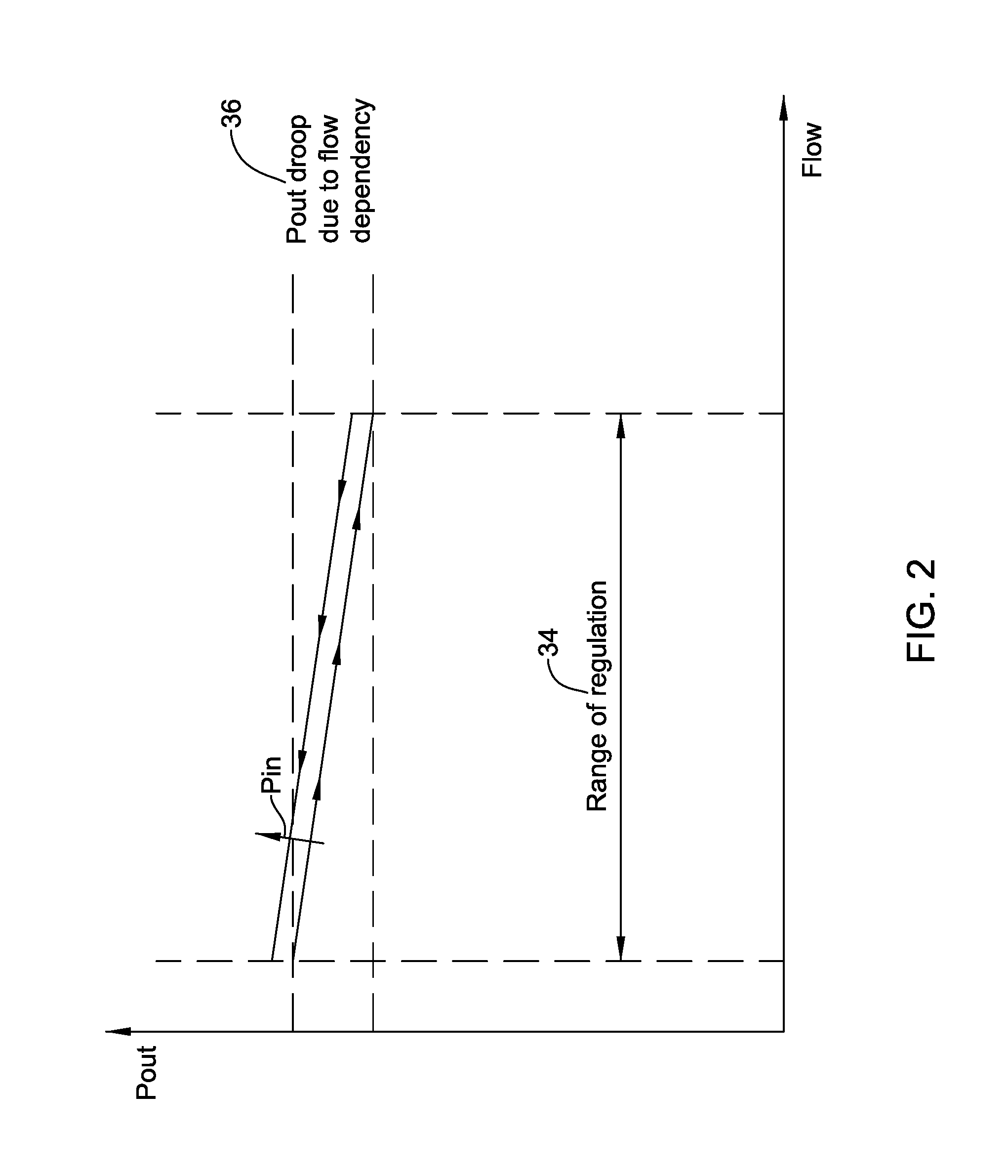
The type of deflection of the diaphragm 12 in FIG. 1 and the resulting adjustment of the position of the valve member 14 relative to the valve seat 32 may introduce a flow-dependent error in the regulated pressure. FIG. 2 is a graph depicting this error. FIG. 2 shows a graph of an illustrative output pressure P.sub.out (i.e. pressure downstream of the valve seat 32) as the flow rate of the fluid flow across the valve member 14 increases over a range of regulation 34. The flow dependent error is evident from the drop in P.sub.out, which is labeled "P.sub.out droop due to flow dependency 36" in FIG. 2, over the range of regulation 34. The droop may be, at least partially, the result of the flow rate of the fluid flow 24 across the valve member 14, causing a flow induced force to act on the valve member 14 and, as the valve member 14 is in communication with (e.g., mechanically connected to) the diaphragm 12, to act on the diaphragm 12, which can affect the set point of the PRV 10 (e.g., reducing the set point) and the resulting regulated output pressure P.sub.out. The flow induced force is dependent on the current flow rate flowing past the valve member 14, which is dependent on the current position of the valve member relative to the valve seat 32. In some cases, a cause of the droop may be due to a valve member moving away from a valve seat to allow additional flow across the valve seat, which may reduce a bias force acting on a diaphragm when a spring is used as a bias mechanism and may lead to requiring less than expected downstream pressure to balance the forces acting on the diaphragm. Additionally, as is shown in the graph of FIG. 2, the pressure P.sub.in upstream of the valve seat 32 may affect the P.sub.out reading due to hysteresis caused at least in part by the flow induced force.
FIG. 3 is a schematic cross-sectional view of an illustrative improved pressure regulator assembly 100. The illustrative pressure regulator assembly 100 may include a pressure sensor 102, a controller 104 in communication with the pressure sensor 102, and a valve actuator 106. Such a pressure regulator assembly 100 may control output pressure P.sub.out regardless of input pressure and/or flow rates.
In the pressure regulator assembly 100 as compared to the PRV 10, electronics may be utilized to control the position of a valve in the flow channel 26, rather than controlling the valve position directly via the diaphragm 12 (see FIG. 1). For example, in the pressure regulator assembly 100, the valve actuator 106 drives the valve (e.g., a valve member 108 and connected valve stem 110) to adjust a pressure downstream of a valve seat 112 (e.g., a Pont) in response to a pressure value sensed by the pressure sensor 102. In operation, the valve actuator 106 may drive the valve until the pressure sensor 102 senses a set pressure. In such a pressure regulator assembly 100, the set pressure may be independent of flow rates and inlet pressure, and droop or error (e.g., error caused by hysteresis or other error) in P.sub.out may be reduced or eliminated.
The pressure sensor 102 may include a housing 114 having an exterior 114a and an interior 114b. A bias mechanism or a bias 116 (e.g., a spring) may be positioned at least partially within the interior 114b of the housing 114, and may act on a diaphragm 118 to apply a bias force or pressure thereon. In the example shown, the bias force or pressure applied to the diaphragm 118 by the bias 116 may be adjusted by adjusting (e.g., activating) a bias adjuster 120 (e.g., a bias or spring or spring-force adjusting mechanism) in communication with and/or acting on the bias 116.
The bias adjuster 120 may be any type of mechanism configured to adjust an amount of bias pressure/force that is applied to the diaphragm 118 by the bias 116. For example, the bias adjuster may be or may include a motor (e.g., a stepper motor, a servo motor, or other motor), a threaded mechanism (e.g., an adjustable screw or other threaded mechanism) that may engage threads of housing 114 and acts on the bias 116 as the threaded mechanism is threaded with threads of the housing 114, and/or one or more other bias adjusters 120 capable of adjusting an amount of force/pressure applied to the diaphragm 118 by the bias 116. In one example of when the bias adjuster 120 is threadedly engaged with threads of the housing 114, the bias adjuster may be rotated to advance or withdraw and change the amount of force/pressure applied to the diaphragm 118 by the bias 116.
The bias 116 may act directly on the diaphragm 118 or indirectly on the diaphragm 118 via stem 122 or other mechanism. A first end of the stem 122 may be in communication with the bias 116 and a second end of the stem 122 may be in communication with the diaphragm 118.
The pressure sensor 102 may further include a position sensor 124. In the example shown, the position sensor 124 may sense a position of the stem 122, which may be configured to move with movement of the diaphragm 118, which moves with changes in pressure downstream of the valve seat 112 (e.g., P.sub.out). The stem 122 and/or the position sensor 124 may be positioned on a first side or a second side of the diaphragm 12, such that the position sensor 124 may sense the axial position of the stem 122.
The diaphragm 118 may be positioned within the housing 114 such that a first side (e.g. back side) of the diaphragm may face the bias 116 and a second side (e.g. front side) of the diaphragm may face the orifice 28 and/or fluid channel (e.g., a channel in fluid communication with the fluid flow 24 in the flow channel 26. The bias 116 may apply a force to the first side (e.g. back side) of the diaphragm 118, either directly or through another mechanism (e.g., stem 122 or other feature), which may be maintained unless the bias 116 is being adjusted. A force may be applied to a second side (e.g. front side) of the diaphragm 118 by a pressure in the flow channel 26. As the force applied to the first side (e.g. back side) of the diaphragm 118 acts as a reference for the pressure sensor 102 (e.g., the diaphragm 118), the diaphragm 118 may deflect when there is a change in pressure in the flow channel 26.
In response to a deflection or other movement of the diaphragm 118 due to a change in pressure in the flow channel 26, the stem 122 in communication with the diaphragm 118 longitudinally or axially translates. The position sensor 124 may sense the change in position of the stem 122 and/or simply a current position of the stem 122.
The pressure sensor 102 may have one or more benefits. For example, the pressure sensor 102 with a biased (e.g., a spring biased) diaphragm 118 and a position sensor 124 (e.g., when an LVDT pressure sensor or other similar pressure sensor is utilized) may provide accurate pressure readings around a zero-position of the diaphragm 118 (discussed below) and low drift in the pressure readings that can be caused by temperature and age of the pressure sensor 102.
The pressure regulator assembly 100 may be configured to keep the diaphragm 118 at a zero-position (e.g., a null position). The zero-position represents the, or substantially the, desired regulated pressure set point for the pressure regulator assembly 100. The zero-position of the diaphragm 118 is a position of the diaphragm 118 when the force applied thereto by the bias 116 is equal to or substantially equal to the force due to pressure in the flow channel 26 downstream of the valve member 108. To keep the diaphragm 118 at a zero position, the position sensor 124 may sense a position of the stem 122 and send the position of the stem 122 to the controller 104. If the position sensor 124 and/or the controller 104 identify that the stem 122 is not at a position indicative of a zero-position of the diaphragm 118, the controller 104 may send a signal (e.g., to the valve actuator 106) to adjust the valve member 108 relative to the valve seat 112. This will adjust the pressure on the diaphragm 118, and thus the position of the diaphragm 118, toward the zero-position. This feedback path may be used to regulate the pressure in the flow channel 26 downstream of the valve member 108. Further, although the pressure regulator assembly 100 may be described herein as utilizing a zero-position, the pressure regulator assembly 100 may rely on a different position of the diaphragm 118 and/or other configuration for regulating a pressure.
FIG. 4 shows a graph of an illustrative output pressure P.sub.out (i.e. pressure downstream of the valve seat 112 as the flow rate of the fluid flow across the valve member 108 increases over a range of regulation 34. As can be seen in FIG. 4, the configuration of the pressure regulator assembly 100 is able to maintain a constant or substantially constant pressure downstream of the valve member 108 (P.sub.out) over the range of regulation 34 (e.g., which may be a predefined range of flow rates) and a range of input pressures P.sub.in (e.g., a predefined range of input pressures at an input port of the flow channel 26). As can be seen, the regulated output pressure P.sub.out may be independent of or substantially independent of flow rate of the fluid flow 24 across the valve seat 112, and may not have any or substantially any hysteresis across the range of pressure inputs P.sub.in. From this, it may be seen that the set bias 116 applied to the diaphragm 118 may produce a corresponding constant or substantially constant regulated output pressure P.sub.out of the pressure regulator assembly 100.
The term "substantially" may be considered to be plus or minus five percent (5%) of a desired variable value over a range or ranges of dependent variable(s). For example, a substantially constant pressure downstream of a valve seat 112, referred to here as P.sub.out, over a range of regulation 34, may be plus or minus 5% of a desired regulated pressure value over the range of regulation 34. In some cases, the pressure regulator valve assembly 100 may be able to maintain a pressure downstream of a valve seat 112 within plus or minus one percent (1%), two percent (2%), five percent (5%), ten percent (10%), fifteen percent (15%), or twenty percent (20%) of a desired regulated pressure value over the range of regulation 34.
When compared to the pressure regulating valve 10, the pressure regulator assembly 100 may produce a constant or substantially constant regulated pressure P.sub.out due, at least in part, to mechanically separating the positioning of the valve member 108 and the diaphragm 118. For example, because the diaphragm 118 of the pressure sensor 102 is not mechanically connected to the valve member 108, the valve member 108 does not mechanically act on the diaphragm in response to flow induced forces acting on the valve member 108, which affected the regulated output pressure of the PRV 10. Thus, the set point of the pressure sensor 102 is maintained constant or substantially constant over the flow rates of the fluid flow across the valve seat 112, resulting in no or substantially no P.sub.out droop due to flow dependency and no or substantially no hysteresis with changes in P.sub.in.
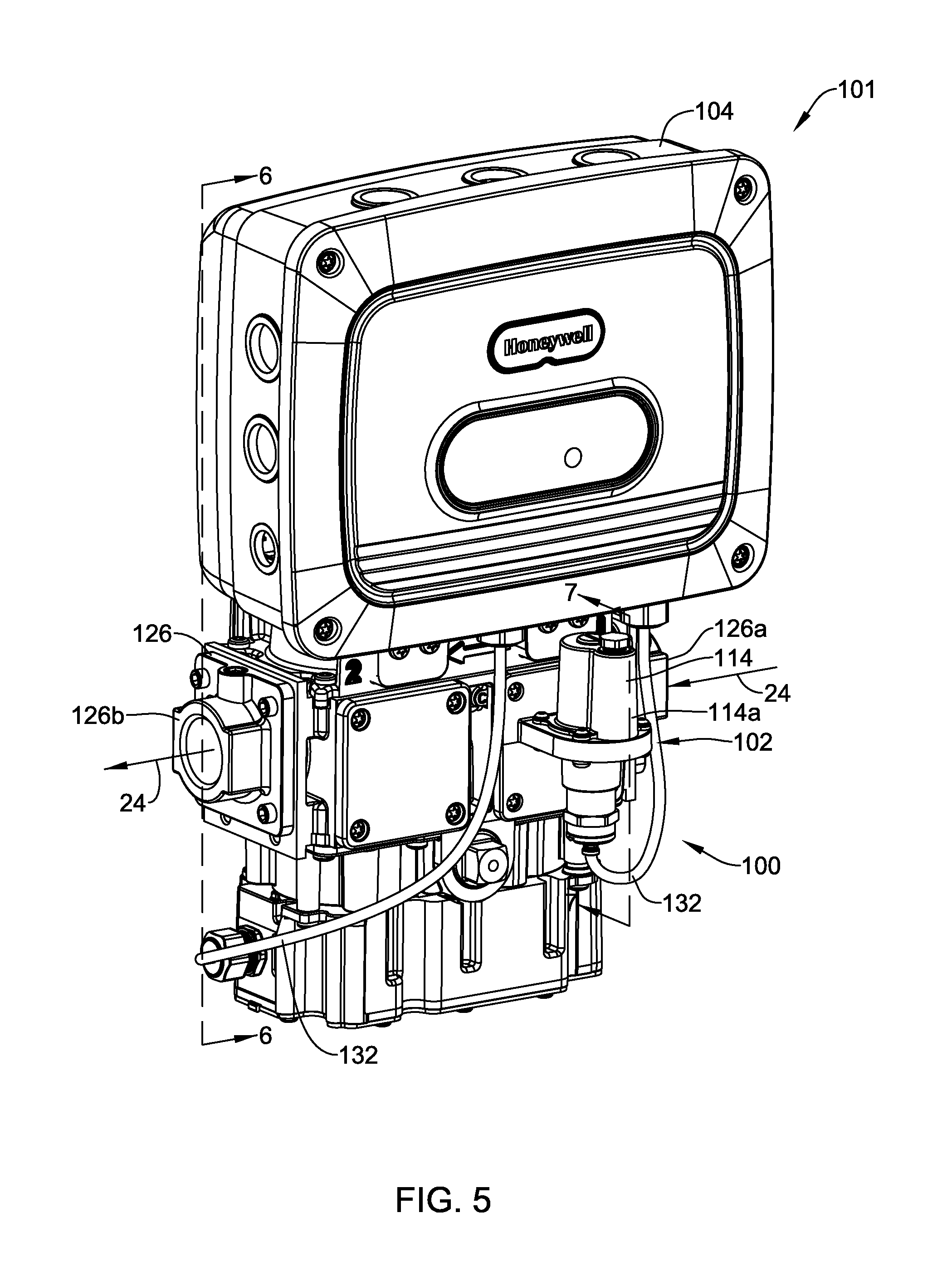
FIG. 5 is a schematic perspective view of an illustrative valve assembly 101 for controlling fuel flow to a combustion appliance. FIG. 6 is a cross-section taken along line 6-6 of FIG. 5 and depicts a cross-sectional view of the housing 126. FIG. 7 is a schematic cross-sectional view of the illustrative valve assembly 101 of FIG. 5, taken along line 7-7.
The illustrative valve assembly 101 may include a housing 126 with an inlet port 126a and an outlet port 126b, with a flow channel extends there between. The illustrative valve assembly 101 may further include a pressure regulator assembly 100 including a pressure sensor 102 and a controller 104. The controller 104 may be in operative communication with the pressure sensor 102 and one or more valve actuators 106 in the housing 126 (see FIG. 6). The illustrative valve assembly 101 may include one or more valve members 108 between the inlet port 126a and the outlet port 126b, where the valve actuators 106 control the position of the valve members 108. In some cases, the valve actuators 106 may be secured relative to the valve body or housing 126 and selectively move one or more of the valve members 108 relative to a first axis between a closed position, which closes the fluid path between the inlet port 126a and the outlet port 126b, and an open position.
The pressure regulator assembly 100 may include and/or be in communication with one or more of the valve members 108. For example, the pressure regulator assembly 100 may be in communication with a first valve member 108 and a second valve member 108 in the flow path or channel via one or more valve actuators 106. In such an example, the controller 104 may receive a position of the stem 122 or diaphragm 118 from the position sensor 124 and send a signal to one or more of the valve actuators 106 to adjust a position of the first valve member 108 and/or the second valve member 108 to re-position the diaphragm to the null position.
As best shown in FIG. 6, the housing 126 includes inlet port 126a and outlet port 126b, and a flow channel extending between the inlet port 126a and the outlet port 126b. The inlet port 126a is shown upstream of one or more valve members (e.g., valve member 108) and the outlet port 126b is shown downstream of the one or more valve members, where a pressure at the inlet port 126a may be considered an input pressure (e.g., P.sub.in) and a pressure at the outlet port 126b may be considered an output pressure (e.g., P.sub.out). Although the housing 126 is shown with two valve members 108 (e.g., two valve disks), the housing 126 may have a single valve member or more than two valve members.
A valve actuator 106 may be in communication with, coupled to, and/or coupled with the valve member 108 (e.g., a valve disk). The valve actuator 106 may be in communication with, coupled to, and/or coupled with the controller 104 and the valve member to control a position of the valve member. By controlling the position of the valve member 108, the valve actuator 106 may control a flow rate of the fluid flow 24 through the flow channel.
As best shown in FIG. 7, the pressure sensor 102 may include a diaphragm 118 and one or more sense elements 144 for sensing the current position of the diaphragm 118. The diaphragm 118 may separate (e.g., fluidly separate) or at least partially separate (e.g., at least partially fluidly separate) a pressure sensing chamber 128 from a reference chamber 130. The pressure sensing chamber 128 may be in fluid communication with the flow channel downstream of the valve member 108. The reference chamber 130 may be sealed, have a release valve/vent 142 (e.g., a vent limiting orifice), and/or may be in fluid communication with atmosphere, a combustion chamber, and/or other appropriate pressure reference, depending on the application. When provided, the release valve/vent 142 may dampen a transient response of the pressure regulator assembly 100 due to pressure fluctuations, and a size of an orifice of the release valve/vent 142 may be adjusted to change (e.g., improve) the dynamic performance of the pressure regulator assembly 100.
A bias mechanism 116 may be included in the pressure sensor 102 for applying a bias force (e.g., a pressure) to the back side of the diaphragm 118. The bias mechanism 116 may apply a bias force to the diaphragm 118 in a direction toward the pressure sensing chamber. As such, a pressure differential (e.g., a positive or negative pressure differential) between the pressure sensing chamber 128 and reference chamber 130 may provide a counter force (e.g., from the pressure in the pressure sensing chamber 128) to the bias force applied to the diaphragm 118 by the bias mechanism 116. Thus, a current position of the diaphragm 118 may be dependent on a differential between the bias force and the counter force. The current position of the diaphragm 118 may be detected by a position sensor, such as position sensor 124.
In one example of a counter force acting on a diaphragm 118, the counter force may decrease when the pressure differential between the pressure sensing chamber 128 and the reference chamber 130 decreases. Similarly, the counter force may increase when the pressure differential between the pressure sensing chamber 128 and the reference chamber 130 increases. As the counter force changes, so does the position of the diaphragm 118. The position sensor 124 may detect the position of the diaphragm 118, which may reflect the pressure in the pressure sensing chamber 128 (and thus the pressure in the flow channel downstream of the valve member 108).
As shown in FIG. 7, a stem 122 may be operatively coupled to the diaphragm 118. The stem 122 may extend toward and/or through the pressure sensing chamber 128 (as shown in FIG. 7) or toward and/or through the reference chamber 130 (not shown). In FIG. 7, the position sensor 124 may be utilized for sensing the axial position of the stem 122, and because the stem 122 is operatively coupled to the diaphragm 118, the position sensor 124 may detect a change in pressure in the pressure sensing chamber 128. Thus, the diaphragm 118 may translate a pressure in the flow channel downstream of the valve member 108 into a position value of the stem 122, and the position sensor 124 may translate the position value of the stem into an electrical value (e.g., an electrical signal) to be sent to the controller 104. The position sensor 124 may be configured to detect the axial position of the stem 122 and, in some cases, send the axial position of the stem 122 to the controller 104 for analysis.
The position sensor 124 may include one or more sense elements 144 and one or more field sensors 146, where the field sensors 146 may detect one or more of the sense elements 144. In some cases, the one or more sense elements 144 may be connected to or formed with the stem 122. As such, the one or more sense elements 144 and/or the field sensors 146 may be in operative communication with the diaphragm 118.
In some cases, the one or more sense elements 144 may include a marking, a magnet, a ferrous core, and/or other sense element 144 that may be attached to or formed with the stem 122. A field sensor 146 may be an optical sensor, a magnetic field sensor, a Linear Variable Differential Transformer (LVDT), a Hall Effect sensor, and/or any other suitable field sensor 146. The stem 122 may have a range of travel and the field sensor may sense a current axial position of the stem 122 (e.g., the axial position of the sense element on the stem 122) along the range of travel of the stem 122.
In one example, the field sensor 146 may be a LVDT and the sense element may be a ferrous core of or attached to the stem 122. In this example, the LVDT may have a null position output when it sense the ferrous core of the stem 122 at a null position. In some cases, a null position may be when the counter force acting on the diaphragm 118 is equal to or substantially equal to a set point force/pressure (e.g., a bias force/pressure applied to the diaphragm 118 by a bias 116). With an LVDT field sensor 146, temperature may be relatively easily derived by the controller 104 by delivering and measuring a current through the LVDT coils. Since the LVDT coils often have a known relationship between resistance in the LVDT coils and temperature, the controller 104 may calculate the current temperature in the valve. The controller 104 may then use this calculated temperature to perform temperature compensation so that the regulated output pressure P.sub.out is also constant or substantially constant over a predetermined temperature range.
The field sensor 146 may be positioned within the housing 114 and/or may be positioned exterior to the housing 114. In some cases the field sensor 146 is positioned exterior to the housing 114 and radially spaced from a longitudinal axis of stem 122. Field sensors 146 may be positioned so as to be entirely exterior to fluid flow through the flow channel The meaning of entirely exterior of fluid channel may include all field sensors 146 and all electronics (e.g., wires, circuit boards) connected to position sensor(s) 48 being exterior to the fluid channel. This may be beneficial when the fluid flow is natural gas or the like for a combustion appliance, where it is often not desirable to have electrical components in direct contact with the gas as this may present a fire hazard. In some cases, the field sensor 146 may be spaced from the one or more sense elements 144 on the stem 122 such that the field sensor 146 may detect a position of the one or more sense elements 144 and thus, the position of the stem 122 through the housing 114. Where field sensor(s) 146 include(s) an LVDT, the LVDT may be positioned concentrically around and radially spaced from stem 122, as best shown in FIG. 7, or in a different position if desired.
FIGS. 8 and 9 show alternative pressure regulators 102. In FIG. 8, the bias 116 is positioned at least partially within the stem 122 and extends to a position near the diaphragm 118. In FIG. 9, the bias 116 is positioned substantially entirely above the stem 122 and extends between the bias adjuster 120 and a stem seat 148. In these examples, the bias 116 applies a force/pressure to the stem 122, which in turn applies a force/pressure to the diaphragm 118.
As discussed and shown in FIGS. 5 and 10, the controller 104 may be operatively coupled to and/or in communication with the valve actuator 106 and the position sensor 124. In some cases, the controller 104 may be coupled to the valve actuator 106 and/or the position sensor 124 via one or more electrical connectors 132, such as shown in FIG. 5. In one example, and as shown in FIG. 10, the controller 104 may include a processor 134, a memory 136, an input/output port 138, user interface 140, and/or one or more other components.
It is contemplated that the controller 104 may be physically secured to or coupled to, or secured or coupled relative to, the valve housing 126. In some instances, controller 104 may be considered a portion of the pressure sensor 102 or valve assembly 101 (e.g., including housing 126, valve members 108, and/or valve actuator 106), the pressure sensor 102 or valve assembly 101 may be considered a portion of the controller 104, or one or more of the controller 104, the pressure sensor 102, and the valve assembly 101 may be considered separate systems or devices.
The controller 104 may control the valve actuator(s) 106 and thus a position of the valve member(s) 108. The position of the valve member 108 may be controlled based, at last in part, on a current position of the diaphragm 118 (e.g., via the stem in communication with the diaphragm 118 or via another feature indicative of a position of the diaphragm, including the diaphragm). The position of the valve member 108 may be controlled by the controller 104 to drive the current position of the diaphragm 118 to a control position that results in a constant or substantially constant pressure at the output port of the housing, P.sub.out, over a predefined range of fluid flow rates and a predefined range of input pressures. In some cases, the control position of the diaphragm 118 corresponds to a null position output of a LVDT position sensor 124, and the controller 104 may instruct the valve actuator 106 to move the valve member 108 such that the one or more sense elements 144 are driven to the null position, and the diaphragm 118 is driven to a control position. In such a case, a constant or substantially constant pressure at the output port of the housing, P.sub.out, may result over a predefined range of flow rates, a predefined range of input pressures, and/or a predefined range of temperatures.
The memory 136, which in some cases may be part of controller 104, may be configured to record data related to sensed pressures (e.g., positions of the diaphragm, etc.), sensed differential pressures, sensed temperatures, and/or other measures. The controller 104 may access this data, and in some cases, communicate (e.g., through a wired or wireless communication link) the data and/or analyses of the data to other systems (e.g., a system level or central building control). The memory 136 and/or other memory may be programmed and/or developed to contain software to affect one or more of the configurations described herein.
As disclosed herein, the pressure regulator assembly 100 may be utilized in an illustrative method 150 of regulating a pressure in a flow channel, as shown in FIG. 11. The method 150 may include translating 152 a pressure in the flow channel into a position of a diaphragm 118 of the pressure sensor 102. The diaphragm 118 may fluidly or otherwise separate a pressure sensing chamber 128 and a reference chamber 130, where the pressure sensing chamber 128 may be in fluid communication with the pressure in the flow channel and the diaphragm may move in response to changes in differential pressure between the pressure sensing chamber 128 and the reference chamber 130.
The position of the diaphragm 118 may be dependent on the pressure in the flow channel and thus, when the pressure in the flow channel changes, the position of the diaphragm 118 changes. The position of the diaphragm 118 may be sensed 154. In one example, the position of the diaphragm may be sensed with a position sensor 124. The position sensor 124 may be an LVDT or other position sensor, where the LVDT or other position sensor may be capable of sensing a range of positions of the diaphragm 118 including a null position.
The method 150 may further include controlling 156 a position of a valve member 108 in the flow channel of the pressure regulator assembly 100 to adjust the pressure in the flow channel acting on the diaphragm 118. Such control of the valve member 108 may be based on the sensed position of the diaphragm 118 so that the sensed position of the diaphragm 118 is driven toward a predetermined position (e.g., a position corresponding to the null position). In one example, the valve member 108 may be controlled to maintain a constant or substantially constant pressure in the flow channel over a predefined range of flow rates through the flow channel, over a predefined range of input pressures, and/or over a predefined range of temperatures.
Those skilled in the art will recognize that the present disclosure may be manifested in a variety of forms other than the specific embodiments described and contemplated herein. Accordingly, departure in form and detail may be made without departing from the scope and spirit of the present disclosure as described in the appended claims.
* * * * *
References
D00000
D00001
D00002
D00003
D00004
D00005
D00006
D00007
D00008
D00009
D00010
D00011
XML
uspto.report is an independent third-party trademark research tool that is not affiliated, endorsed, or sponsored by the United States Patent and Trademark Office (USPTO) or any other governmental organization. The information provided by uspto.report is based on publicly available data at the time of writing and is intended for informational purposes only.
While we strive to provide accurate and up-to-date information, we do not guarantee the accuracy, completeness, reliability, or suitability of the information displayed on this site. The use of this site is at your own risk. Any reliance you place on such information is therefore strictly at your own risk.
All official trademark data, including owner information, should be verified by visiting the official USPTO website at www.uspto.gov. This site is not intended to replace professional legal advice and should not be used as a substitute for consulting with a legal professional who is knowledgeable about trademark law.