Internally cooled spoke
Sanchez , et al. Dec
U.S. patent number 10,502,095 [Application Number 15/340,353] was granted by the patent office on 2019-12-10 for internally cooled spoke. This patent grant is currently assigned to United Technologies Corporation. The grantee listed for this patent is United Technologies Corporation. Invention is credited to William A. Daniels, Kalpendu J. Parekh, Paul K. Sanchez, John S. Tu.


| United States Patent | 10,502,095 |
| Sanchez , et al. | December 10, 2019 |
Internally cooled spoke
Abstract
A turbine engine includes a compressor section, a combustor section in fluid communication with the compressor section, a high pressure turbine in fluid communication with the combustor, a low pressure turbine in fluid communication with the high pressure turbine, and a mid-turbine frame located axially between the high pressure turbine and the low pressure turbine. The mid-turbine frame includes an outer frame case, an inner frame case, and a plurality of hollow spokes that distribute loads from the inner frame case to the outer frame case. The spokes are hollow to allow cooling airflow to be supplied through the spokes to the inner frame case.
| Inventors: | Sanchez; Paul K. (Wellington, FL), Parekh; Kalpendu J. (Colchester, CT), Daniels; William A. (Marlborough, CT), Tu; John S. (West Hartford, CT) | ||||||||||
|---|---|---|---|---|---|---|---|---|---|---|---|
| Applicant: |
|
||||||||||
| Assignee: | United Technologies Corporation
(Farmington, CT) |
||||||||||
| Family ID: | 48869074 | ||||||||||
| Appl. No.: | 15/340,353 | ||||||||||
| Filed: | November 1, 2016 |
Prior Publication Data
| Document Identifier | Publication Date | |
|---|---|---|
| US 20170044985 A1 | Feb 16, 2017 | |
Related U.S. Patent Documents
| Application Number | Filing Date | Patent Number | Issue Date | ||
|---|---|---|---|---|---|
| 13753821 | Jan 30, 2013 | 9512738 | |||
| 13361480 | Apr 19, 2016 | 9316117 | |||
| Current U.S. Class: | 1/1 |
| Current CPC Class: | F01D 25/24 (20130101); F01D 25/12 (20130101); F02K 3/04 (20130101); F01D 25/14 (20130101); F02C 7/12 (20130101); F01D 25/162 (20130101); F02C 7/20 (20130101); F05D 2260/20 (20130101); F01D 25/246 (20130101); F05D 2220/36 (20130101); F01D 25/16 (20130101) |
| Current International Class: | F02C 7/12 (20060101); F01D 25/12 (20060101); F01D 25/14 (20060101); F01D 25/16 (20060101); F02K 3/04 (20060101); F02C 7/20 (20060101); F01D 25/24 (20060101) |
References Cited [Referenced By]
U.S. Patent Documents
| 2620157 | December 1952 | Morley et al. |
| 2829014 | April 1958 | May |
| 2869941 | January 1959 | Shoup, Jr. et al. |
| 2919888 | January 1960 | Simmons |
| 3312448 | April 1967 | Hull, Jr. et al. |
| 3734639 | May 1973 | Short |
| 4135362 | January 1979 | Glenn |
| 4304522 | December 1981 | Newland |
| 4478551 | October 1984 | Honeycutt, Jr. et al. |
| 4979872 | December 1990 | Myers et al. |
| 4987736 | January 1991 | Ciokajlo et al. |
| 5076049 | December 1991 | VonBenken et al. |
| 5160251 | November 1992 | Ciokajlo |
| 5272869 | December 1993 | Dawson et al. |
| 5292227 | March 1994 | Czachor et al. |
| 5326222 | July 1994 | Matyscak et al. |
| 5357744 | October 1994 | Czachor et al. |
| 5438756 | August 1995 | Halchak et al. |
| 5483792 | January 1996 | Czachor et al. |
| 5517817 | May 1996 | Hines |
| 5537814 | July 1996 | Nastuk et al. |
| 5609467 | March 1997 | Lenhart et al. |
| 5634767 | June 1997 | Dawson |
| 5746574 | May 1998 | Czachor et al. |
| 6217279 | April 2001 | Ai et al. |
| 6227799 | May 2001 | Kuhn et al. |
| 6267553 | July 2001 | Burge |
| 6358001 | March 2002 | Bosel et al. |
| 6439841 | August 2002 | Bosel |
| 6450763 | September 2002 | Crum et al. |
| 6547518 | April 2003 | Czachor et al. |
| 6708482 | March 2004 | Seda |
| 6835044 | December 2004 | Frosini |
| 6860716 | March 2005 | Czachor et al. |
| 6935837 | August 2005 | Moniz et al. |
| 7011493 | March 2006 | Marchi et al. |
| 7124572 | October 2006 | Aycock et al. |
| 7195447 | March 2007 | Moniz et al. |
| 7326030 | February 2008 | Albrecht et al. |
| 7383686 | June 2008 | Aycock et al. |
| 7673461 | March 2010 | Cameriano et al. |
| 7797946 | September 2010 | Kumar et al. |
| 8061969 | November 2011 | Durocher et al. |
| 8091371 | January 2012 | Durocher et al. |
| 8099962 | January 2012 | Durocher et al. |
| 8245518 | August 2012 | Durocher et al. |
| 8347635 | January 2013 | Durocher et al. |
| 8500392 | August 2013 | Durocher et al. |
| 8511969 | August 2013 | Durocher et al. |
| 2005/0132715 | June 2005 | Allen, Jr. et al. |
| 2006/0123796 | June 2006 | Aycock et al. |
| 2006/0130456 | June 2006 | Suciu |
| 2008/0022692 | January 2008 | Nagendra et al. |
| 2010/0021286 | January 2010 | Somanath et al. |
| 2010/0132371 | June 2010 | Durocher et al. |
| 2010/0132372 | June 2010 | Durocher et al. |
| 2010/0132373 | June 2010 | Durocher et al. |
| 2010/0132374 | June 2010 | Manteiga et al. |
| 2010/0132377 | June 2010 | Durocher et al. |
| 2010/0135777 | June 2010 | Durocher et al. |
| 2010/0303610 | December 2010 | Wang et al. |
| 2011/0079019 | April 2011 | Durocher et al. |
| 2013/0011242 | January 2013 | Beeck et al. |
| 1378632 | Jan 2004 | EP | |||
| 1482130 | Dec 2004 | EP | |||
Other References
|
International Search Report and Written Opinion from PCT Application Serial No. PCT/US2013/023753, dated Sep. 27, 2013, 8 pages. cited by applicant . International Preliminary Report on Patentability from PCT Application Serial No. PCT/US2013/023753, dated Aug. 5, 2014, 5 pages. cited by applicant . Extended European Search Report for EP Application No. 13778601.8, dated Oct. 19, 2015, 5 pages. cited by applicant . Extended European Search Report, for European Patent Application No. 16203022.5, dated Apr. 10, 2017, 6 pages. cited by applicant . Extended European Search Report for EP Application No. 19175358.1, dated Jun. 28, 2019, 6 pages. cited by applicant . Communication of a Notice of Opposition for European Patent No. 2809919, dated Sep. 15, 2017, 36 pages. cited by applicant. |
Primary Examiner: Sutherland; Steven M
Attorney, Agent or Firm: Kinney & Lange, P.A.
Parent Case Text
CROSS-REFERENCE TO RELATED APPLICATION(S)
This application is a continuation of U.S. patent application Ser. No. 13/753,821, filed Jan. 20, 2013 and entitled "Internally Cooled Spoke", which is a continuation of U.S. patent application Ser. No. 13/361,480, filed Jan. 30, 2012 and entitled "Internally Cooled Spoke".
Claims
The invention claimed is:
1. A turbine engine comprising: a combustor; a first spool comprising a high pressure compressor connected to a high pressure turbine; a second spool comprising a low pressure compressor connected to a low pressure turbine; and a mid-turbine frame located axially between the high pressure turbine and the low pressure turbine, the mid-turbine frame having an outer frame case connected to an inner frame case via a plurality of cooled spokes, wherein each of the plurality of cooled spokes has a radially outer end and a radially inner end and is hollow within a spoke wall for supplying cooling airflow from outside the outer frame case to the inner frame case, wherein the inner frame case includes a manifold defined by an outer diameter annular portion, an inner diameter annular portion, first and second radial portions of the inner frame case that extend radially between the outer diameter annular portion and the inner diameter annular portion, and wherein a radially inner end of the spoke wall of each of the plurality of cooled spokes meets the outer diameter annular portion of the manifold at an opening in the outer diameter annular portion extending from a radially outer surface of the outer diameter annular portion and a radially inner surface of the outer diameter annular portion, and terminates between the radially outer surface of the outer diameter annular portion and the radially inner surface of the outer diameter annular portion to define an airflow path from each of the plurality of cooled spokes into the manifold that allows the manifold to receive and combine the cooling airflow from the plurality of cooled spokes.
2. The turbine engine of claim 1, wherein the mid-turbine frame includes three or more of the plurality of cooled spokes evenly distributed around the inner frame case.
3. The turbine engine of claim 1, wherein the outer frame case includes a plurality of bosses located on an outer surface of the outer frame case for attachment to each of the plurality of cooled spokes.
4. The turbine engine of claim 1, wherein the second spool further comprises: a gearbox connected to at least one of the low pressure compressor and low pressure turbine; and a fan connected to the gearbox.
5. A mid-turbine frame located in a gas turbine engine axially aft of a high pressure turbine and fore of a low pressure turbine, the mid-turbine frame comprising: an outer frame case; an inner frame case; and a plurality of hollow spokes each having a spoke wall with a radially outer end and a radially inner end, the spoke wall being attached between the outer frame case and the inner frame case to distribute force from the inner frame case to the outer frame case, wherein each of the plurality of hollow spokes is configured to receive a cooling airflow therethrough; wherein the inner frame case includes a manifold defined by an outer diameter annular wall, an inner diameter annular wall, and first and second axial walls of the inner frame case that extend radially between the outer diameter annular wall and the inner diameter annular wall; and wherein a radially inner end of the spoke wall of each of the plurality of hollow spokes meets the outer diameter annular wall of the manifold at an opening in the outer diameter annular wall of the manifold and terminates radially between a radially outer surface of the outer diameter annular wall and a radially inner surface of the outer diameter annular wall to define an airflow path from each of the plurality of hollow spokes into the manifold that allows the manifold to receive and combine the cooling airflow provided via the plurality of hollow spokes.
6. The mid-turbine frame of claim 5, wherein the mid-turbine frame includes three or more of the plurality of hollow spokes evenly distributed around the inner frame case.
7. The mid-turbine frame of claim 5, wherein the outer frame case includes a plurality of bosses located on an outer surface of the outer frame case for attachment to each of the plurality of hollow spokes.
8. The mid-turbine frame of claim 5, wherein the high pressure turbine is connected to a high pressure compressor.
9. The mid-turbine frame of claim 5, wherein the low pressure turbine is connected to a low pressure compressor.
10. The mid-turbine frame of claim 9, wherein the low pressure turbine is connected to a fan through a gearbox.
Description
BACKGROUND
The present disclosure relates generally to a gas turbine engine, and in particular to a mid-turbine frame (MTF) included in a gas turbine engine.
A mid-turbine frame (MTF) is positioned between a high pressure turbine stage and a low pressure turbine stage of a gas turbine engine. The MTF supports one or more bearings and transfers bearing loads from an inner portion of the gas turbine engine to an outer engine frame. The MTF also serves to route air from the high pressure turbine stage to the low pressure turbine stage.
SUMMARY
A turbine engine includes a compressor section, a combustor section in fluid communication with the compressor section, a high pressure turbine in fluid communication with the combustor, a low pressure turbine in fluid communication with the high pressure turbine, and a mid-turbine frame located axially between the high pressure turbine and the low pressure turbine. The mid-turbine frame includes an outer frame case, an inner frame case, and a plurality of hollow spokes that distribute bearing loads from the inner frame case to the outer frame case. The spokes are hollow to allow cooling airflow to be supplied through the spokes to the inner frame case.
BRIEF DESCRIPTION OF THE DRAWINGS
FIG. 1 is a schematic view of a gas turbine engine according to an embodiment of the present invention.
FIG. 2 is a perspective view of a mid-turbine frame (MTF) located in the gas turbine engine according to an embodiment of the present invention.
FIG. 3 is a cross-sectional view of mid-turbine frame (MTF) taken along line 3-3 of FIG. 4.
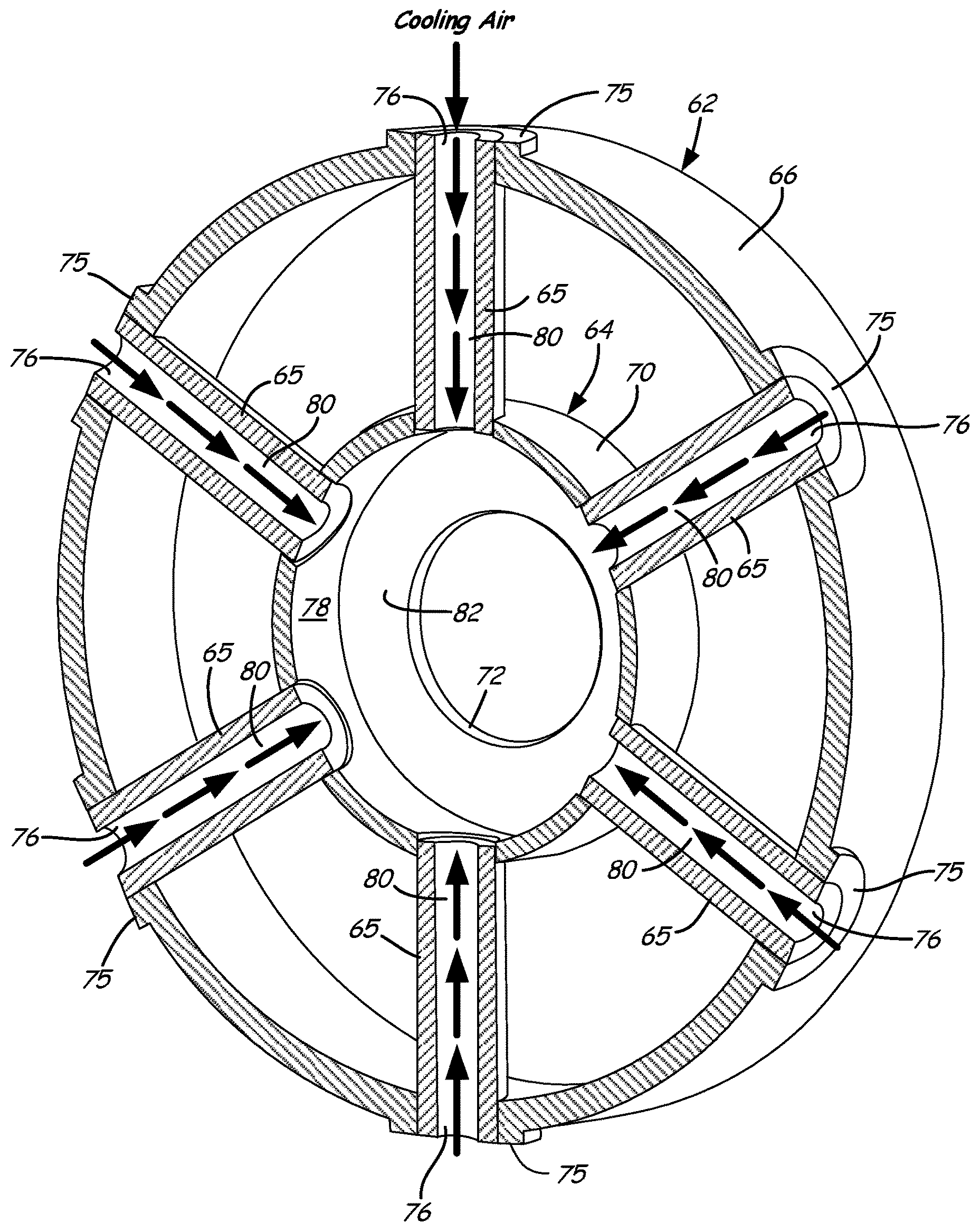
FIG. 4 is a cross-sectional view of mid-turbine frame (MFT) taken along line 4-4 of FIG. 2.
DETAILED DESCRIPTION
FIG. 1 is a schematic view of gas turbine engine 20 according to an embodiment of the present invention. Gas turbine engine 20 is disclosed herein as a two-spool turbofan that generally incorporates fan section 22, compressor section 24, combustor section 26 and turbine section 28, although alternative turbofan designs may benefit from the present invention. Fan section 22 drives air along a bypass flowpath while the compressor section 24 drives air along a core flowpath for compression and communication into the combustor section 26, and then expansion through the turbine section 28.
The engine 20 generally includes low speed spool 30 and high speed spool 32 mounted for rotation about an engine central longitudinal axis A relative to an engine static structure 36 via several bearing systems 38. It should be understood that various bearing systems 38 at various locations may alternatively or additionally be provided.
Low speed spool 30 generally includes inner shaft 40 that interconnects a fan 42, low pressure compressor 44 and low pressure turbine 46. Inner shaft 40 is connected to fan 42 through geared architecture 48 to drive fan 42 at a lower speed than low speed spool 30. High speed spool 32 includes outer shaft 50 that interconnects high pressure compressor 52 and high pressure turbine 54. Combustor 56 is arranged between high pressure compressor 52 and high pressure turbine 54. Mid-turbine frame 57 of the engine static structure 36 is arranged axially between high pressure turbine 54 and low pressure turbine 46. Mid-turbine frame 57 further supports bearing systems 38 in turbine section 28. Inner shaft 40 and outer shaft 50 are concentric and rotate via bearing systems 38 about the engine central longitudinal axis A which is collinear with their longitudinal axes.
The core airflow is compressed by low pressure compressor 44 and then by high pressure compressor 52, mixed and burned with fuel in combustor 56, then expanded over high pressure turbine 54 and low pressure turbine 46. Combustor 56 is therefore in fluid communication with the compressor section, to receive air compressed by low pressure compressor 44 and high pressure compressor 52. Mid-turbine frame 57 includes airfoils 59 which are in the core airflow path. Turbines 46 and 54 are in fluid communication with combustor 56, wherein the expanding gas provided by combustor 56 drives the respective low speed spool 30 and high speed spool 32.
FIG. 2 is a perspective view of mid-turbine frame (MTF) 57 according to an embodiment of the present invention. MTF 57 includes outer frame case 62, inner frame case 64, and a plurality of hollow spokes 65. Outer frame case 62 includes an outer diameter portion 66. Inner frame case 64 includes an outer diameter portion 70 and inner diameter portion 72. In the embodiment shown in FIG. 2, six hollow spokes 65 are distributed evenly around the circumference of radial inner case 64 to provide structural support between inner frame case 64 and outer frame case 62.
Inner frame case 64 supports the rotor assembly via bearing assemblies 38 (shown in FIG. 1), and distributes the force from inner frame case 64 to outer frame case 62 via the plurality of hollow spokes 65. A number of arrangements are possible for attaching hollow spokes 65 to inner frame case 64. In one embodiment, inner frame case includes a plurality of apertures (not shown) for receiving each hollow spoke 65, and one or more bolts for attaching each hollow spoke 65 to inner frame case 64. Attachment of hollow spokes 65 to outer frame case 62 is provided at a plurality of bosses 75 located circumferentially around outer diameter surface 66 of outer frame case 62. In one embodiment, attachment of hollow spokes 65 at bosses 75 may be secured by a nut (not shown) that allows hollow spokes 65 to be tensioned. Apertures 76 formed in each of the plurality of bosses 75 allows cooling air to be distributed into a hollow portion (shown in FIG. 3) of each hollow spoke 65. In this way, cooling airflow is directed from the outer diameter through the hollow portion of cooled spoke 65 towards inner frame case 64. A metering plate (not shown) may be employed to meter or control the flow of cooling airflow into cooled spoke 65. Depending on the application, the size of the metering plate may be adjusted to selectively increase or decrease the volume of cooling air provided to hollow spokes 65. The volume of cooling airflow provided dictates the amount of cooling provided to hollow spokes 65.
Each of the plurality of hollow spokes 65 is subject to a varying temperature gradient caused by the expanding hot gases provided from high pressure turbine section 54 to low pressure turbine section 46 (shown in FIG. 1). If unmitigated, the temperature difference between each of the plurality of hollow spokes 65 results in a thermal growth differential between the plurality of spokes that affects the overall roundness of the engine relative to the centerline axis A (as shown in FIG. 1). The present invention utilizes hollow spokes that receive cooling airflow to mitigate the effects of the hot gas path. The cooling airflow creates a high heat transfer coefficient with the spoke as compared to the heat transfer coefficient outside of the spoke. The resulting difference in heat transfer coefficients results in the cooling airflow within each hollow spoke 65 being the dominant factor in the temperature of spokes 65.
FIG. 3 is a cross-sectional view of mid-turbine frame (MTF) taken along line 3-3 of FIG. 4. FIG. 3 illustrates with respect to each cooled spoke 65 a hollow portion 80 that extends from a first end of cooled spoke 65 attached to the outer frame case 62 to a second end of cooled spoke 65 attached to the inner frame case 64. The cross-sectional view provided in FIG. 3 also illustrates manifold 78 provided within inner frame case 64 for receiving cooling air from each of the plurality of cooled spokes 65 as indicated by the direction of the arrows through hollow portion 80 of each cooled spoke 65. Manifold 78 is defined as the space between outer diameter portion 70 and inner diameter portion 72 of inner frame case 64, and between radial surface 82 and an opposing radial surface (not visible in this view) also of inner frame case 64. Cooling airflow is provided to manifold 78, which combines the cooling airflow from each of the plurality of hollow spokes 65. In one embodiment, airflow provided to manifold 78 is subsequently directed to cool a rotor portion located adjacent to manifold 78.
FIG. 4 is a cross-sectional view of mid-turbine frame (MTF) 57 taken along line 4-4 of FIG. 2 that illustrates the geometry of manifold 78. In particular, manifold 78 is defined by radial portions 82 and 86, outer diameter portion 70 and an inner diameter portion 72 (not visible in this view). Cooling airflow provided via cooled spokes 65 flows into manifold 78 as indicated by the direction of the plurality of arrows through hollow portions 80 of each cooled spoke 65. The present invention therefore compensates for temperature gradients in the mid-turbine frame of a gas turbine engine through utilization of hollow spokes for communicating load forces between an inner frame case and an outer frame case, while being cooled via cooling airflow provided through the hollow portion of each spoke.
While the invention has been described with reference to an exemplary embodiment(s), it will be understood by those skilled in the art that various changes may be made and equivalents may be substituted for elements thereof without departing from the scope of the invention. For example, although depicted as a turbofan gas turbine engine in the disclosed non-limiting embodiment, it should be understood that the concepts described herein are not limited to use with turbofans as the teachings may be applied to other types of turbine engines including three-spool architectures. In addition, many modifications may be made to adapt a particular situation or material to the teachings of the invention without departing from the essential scope thereof. Therefore, it is intended that the invention not be limited to the particular embodiment(s) disclosed, but that the invention will include all embodiments falling within the scope of the appended claims.
* * * * *
D00000
D00001
D00002
D00003
D00004
XML
uspto.report is an independent third-party trademark research tool that is not affiliated, endorsed, or sponsored by the United States Patent and Trademark Office (USPTO) or any other governmental organization. The information provided by uspto.report is based on publicly available data at the time of writing and is intended for informational purposes only.
While we strive to provide accurate and up-to-date information, we do not guarantee the accuracy, completeness, reliability, or suitability of the information displayed on this site. The use of this site is at your own risk. Any reliance you place on such information is therefore strictly at your own risk.
All official trademark data, including owner information, should be verified by visiting the official USPTO website at www.uspto.gov. This site is not intended to replace professional legal advice and should not be used as a substitute for consulting with a legal professional who is knowledgeable about trademark law.