Gel-type thermal interface material
Zhang , et al. Dec
U.S. patent number 10,501,671 [Application Number 15/642,082] was granted by the patent office on 2019-12-10 for gel-type thermal interface material. This patent grant is currently assigned to Honeywell International Inc.. The grantee listed for this patent is Honeywell International Inc.. Invention is credited to Huifeng Duan, Haigang Kang, Ya Qun Liu, Ling Shen, Wei Jun Wang, Kai Zhang, Liqiang Zhang.


View All Diagrams
| United States Patent | 10,501,671 |
| Zhang , et al. | December 10, 2019 |
Gel-type thermal interface material
Abstract
A thermal interface material that is useful in transferring heat from heat generating electronic devices, such as computer chips, to heat dissipating structures, such as heat spreaders and heat sinks. The thermal interface material includes at least one silicone oil, and at least one thermally conductive filler.
| Inventors: | Zhang; Liqiang (Shanghai, CN), Duan; Huifeng (Shanghai, CN), Zhang; Kai (Shanghai, CN), Liu; Ya Qun (Shanghai, CN), Shen; Ling (Shanghai, CN), Wang; Wei Jun (Shanghai, CN), Kang; Haigang (Shanghai, CN) | ||||||||||
|---|---|---|---|---|---|---|---|---|---|---|---|
| Applicant: |
|
||||||||||
| Assignee: | Honeywell International Inc.
(Morris Plains, NJ) |
||||||||||
| Family ID: | 61012470 | ||||||||||
| Appl. No.: | 15/642,082 | ||||||||||
| Filed: | July 5, 2017 |
Prior Publication Data
| Document Identifier | Publication Date | |
|---|---|---|
| US 20180030327 A1 | Feb 1, 2018 | |
Related U.S. Patent Documents
| Application Number | Filing Date | Patent Number | Issue Date | ||
|---|---|---|---|---|---|
| 62436746 | Dec 20, 2016 | ||||
| 62366704 | Jul 26, 2016 | ||||
| Current U.S. Class: | 1/1 |
| Current CPC Class: | C09K 5/14 (20130101); C08K 3/22 (20130101); H05K 7/2039 (20130101); C08K 2003/2296 (20130101); C08K 2201/014 (20130101); C08K 2201/001 (20130101); C08K 2003/2227 (20130101) |
| Current International Class: | C09K 5/14 (20060101); C08K 3/22 (20060101); H05K 7/20 (20060101) |
References Cited [Referenced By]
U.S. Patent Documents
| 4180498 | December 1979 | Spivack |
| 4446266 | May 1984 | von Gentzkow et al. |
| 4459185 | July 1984 | Obata et al. |
| 4565610 | January 1986 | Nobel et al. |
| 4604424 | August 1986 | Cole et al. |
| 5162555 | November 1992 | Remmers et al. |
| 5167851 | December 1992 | Jamison et al. |
| 5562814 | October 1996 | Kirby |
| 6040362 | March 2000 | Mine et al. |
| 6096414 | August 2000 | Young |
| 6238596 | May 2001 | Nguyen et al. |
| 6339120 | January 2002 | Misra et al. |
| 6372337 | April 2002 | Takahashi et al. |
| 6372997 | April 2002 | Hill et al. |
| 6391442 | May 2002 | Duvall et al. |
| 6400565 | June 2002 | Shabbir et al. |
| 6432320 | August 2002 | Bonsignore et al. |
| 6432497 | August 2002 | Bunyan |
| 6451422 | September 2002 | Nguyen |
| 6475962 | November 2002 | Khatri |
| 6496373 | December 2002 | Chung |
| 6500891 | December 2002 | Kropp et al. |
| 6562180 | May 2003 | Bohin et al. |
| 6597575 | July 2003 | Matayabas et al. |
| 6605238 | August 2003 | Nguyen et al. |
| 6610635 | August 2003 | Khatri |
| 6616999 | September 2003 | Freuler et al. |
| 6617517 | September 2003 | Hill et al. |
| 6620515 | September 2003 | Feng et al. |
| 6624224 | September 2003 | Misra |
| 6649325 | November 2003 | Gundale et al. |
| 6657297 | December 2003 | Jewram et al. |
| 6673434 | January 2004 | Nguyen |
| 6706219 | March 2004 | Nguyen |
| 6761928 | July 2004 | Hill et al. |
| 6764759 | July 2004 | Duvall et al. |
| 6783692 | August 2004 | Bhagwagar |
| 6791839 | September 2004 | Bhagwagar |
| 6797382 | September 2004 | Nguyen et al. |
| 6797758 | September 2004 | Misra et al. |
| 6811725 | November 2004 | Nguyen et al. |
| 6815486 | November 2004 | Bhagwagar et al. |
| 6835453 | December 2004 | Greenwood et al. |
| 6838182 | January 2005 | Kropp et al. |
| 6874573 | April 2005 | Collins et al. |
| 6900163 | May 2005 | Khatri |
| 6908669 | June 2005 | Nguyen |
| 6908682 | June 2005 | Mistele |
| 6913686 | July 2005 | Hilgarth |
| 6926955 | August 2005 | Jayaraman et al. |
| 6940721 | September 2005 | Hill |
| 6946190 | September 2005 | Bunyan |
| 6975944 | December 2005 | Zenhausern |
| 6984685 | January 2006 | Misra et al. |
| 7013965 | March 2006 | Zhong et al. |
| 7056566 | June 2006 | Freuler et al. |
| 7074490 | July 2006 | Feng et al. |
| 7078109 | July 2006 | Hill et al. |
| 7135232 | November 2006 | Yamada et al. |
| 7147367 | December 2006 | Balian et al. |
| 7172711 | February 2007 | Nguyen |
| 7241707 | July 2007 | Meagley et al. |
| 7244491 | July 2007 | Nguyen |
| 7291396 | November 2007 | Huang et al. |
| 7294394 | November 2007 | Jayaraman et al. |
| RE39992 | January 2008 | Misra et al. |
| 7328547 | February 2008 | Mehta et al. |
| 7369411 | May 2008 | Hill et al. |
| 7462294 | December 2008 | Kumar et al. |
| 7465605 | December 2008 | Raravikar et al. |
| 7550097 | June 2009 | Tonapi et al. |
| 7572494 | August 2009 | Mehta et al. |
| 7641811 | January 2010 | Kumar et al. |
| 7682690 | March 2010 | Bunyan et al. |
| 7695817 | April 2010 | Lin et al. |
| 7700943 | April 2010 | Raravikar et al. |
| 7744991 | June 2010 | Fischer et al. |
| RE41576 | August 2010 | Bunyan et al. |
| 7816785 | October 2010 | Iruvanti et al. |
| 7646778 | December 2010 | Rumer et al. |
| 7850870 | December 2010 | Ahn et al. |
| 7867609 | January 2011 | Nguyen |
| 7955900 | June 2011 | Jadhav et al. |
| 7960019 | June 2011 | Jayaraman et al. |
| 8039961 | October 2011 | Suhir et al. |
| 8076773 | December 2011 | Jewram et al. |
| 8081468 | December 2011 | Hill et al. |
| 8105504 | January 2012 | Gerster et al. |
| 8110919 | February 2012 | Jewram et al. |
| 8138239 | March 2012 | Prack et al. |
| 8223498 | July 2012 | Lima |
| 8308861 | November 2012 | Rolland et al. |
| 8324313 | December 2012 | Funahashi |
| 8373283 | February 2013 | Masuko et al. |
| 8431647 | April 2013 | Dumont et al. |
| 8431655 | April 2013 | Dershem |
| 8445102 | May 2013 | Strader et al. |
| 8518302 | August 2013 | Gerster et al. |
| 8535478 | September 2013 | Pouchelon et al. |
| 8535787 | September 2013 | Lima |
| 8557896 | October 2013 | Jeong et al. |
| 8586650 | November 2013 | Zhang et al. |
| 8587945 | November 2013 | Hartmann et al. |
| 8618211 | December 2013 | Bhagwagar et al. |
| 8632879 | January 2014 | Weisenberger |
| 8633478 | January 2014 | Cummings et al. |
| 8638001 | January 2014 | Kimura et al. |
| 8647752 | February 2014 | Strader et al. |
| 8758892 | June 2014 | Bergin et al. |
| 8796068 | August 2014 | Stender et al. |
| 8837151 | September 2014 | Hill et al. |
| 8865800 | October 2014 | Stammer et al. |
| 8917510 | December 2014 | Boday et al. |
| 8937384 | January 2015 | Bao et al. |
| 9055694 | June 2015 | Lima |
| 9070660 | June 2015 | Lowe et al. |
| 9080000 | July 2015 | Ahn et al. |
| 9222735 | December 2015 | Hill et al. |
| 9260645 | February 2016 | Bruzda |
| 9392730 | July 2016 | Hartmann et al. |
| 9481851 | November 2016 | Matsumoto et al. |
| 9527988 | December 2016 | Habimana et al. |
| 9537095 | January 2017 | Stender et al. |
| 9593209 | March 2017 | Dent et al. |
| 9593275 | March 2017 | Tang et al. |
| 9598575 | March 2017 | Bhagwagar et al. |
| 10155894 | December 2018 | Liu et al. |
| 2002/0018885 | February 2002 | Takahashi et al. |
| 2002/0132896 | September 2002 | Nguyen |
| 2003/0112603 | June 2003 | Roesner et al. |
| 2003/0128521 | July 2003 | Matayabas, Jr. |
| 2003/0151030 | August 2003 | Gurin |
| 2003/0159938 | August 2003 | Hradil |
| 2003/0203181 | October 2003 | Ellsworth et al. |
| 2003/0207064 | November 2003 | Bunyan et al. |
| 2003/0207128 | November 2003 | Uchiya et al. |
| 2003/0230403 | December 2003 | Webb |
| 2004/0069454 | April 2004 | Bonsignore et al. |
| 2004/0097635 | May 2004 | Fan et al. |
| 2004/0149587 | August 2004 | Hradil |
| 2004/0161571 | August 2004 | Duvall et al. |
| 2004/0206941 | October 2004 | Gurin |
| 2005/0020738 | January 2005 | Jackson et al. |
| 2005/0025984 | February 2005 | Odell et al. |
| 2005/0072334 | April 2005 | Czubarow et al. |
| 2005/0148721 | July 2005 | Tonapi et al. |
| 2005/0228097 | October 2005 | Zhong |
| 2005/0287362 | December 2005 | Garcia-Ramirez et al. |
| 2006/0057364 | March 2006 | Nguyen |
| 2006/0094809 | May 2006 | Simone |
| 2006/0208354 | September 2006 | Liu et al. |
| 2006/0228542 | October 2006 | Czubarow |
| 2006/0260948 | November 2006 | Zschintzsch et al. |
| 2006/0264566 | November 2006 | Cassar et al. |
| 2007/0051773 | March 2007 | Ruchert et al. |
| 2007/0097651 | May 2007 | Canale et al. |
| 2007/0131913 | June 2007 | Cheng et al. |
| 2007/0161521 | July 2007 | Sachdev et al. |
| 2007/0164424 | July 2007 | Dean et al. |
| 2007/0179232 | August 2007 | Collins et al. |
| 2007/0249753 | October 2007 | Lin et al. |
| 2008/0044670 | February 2008 | Nguyen |
| 2008/0116416 | May 2008 | Chacko |
| 2008/0141629 | June 2008 | Alper et al. |
| 2008/0149176 | June 2008 | Sager et al. |
| 2008/0291634 | November 2008 | Weiser |
| 2006/0302064 | December 2008 | Rauch |
| 2009/0111925 | April 2009 | Burnham et al. |
| 2009/0184283 | July 2009 | Chung et al. |
| 2010/0048435 | February 2010 | Yamagata et al. |
| 2010/0048438 | February 2010 | Carey et al. |
| 2010/0075135 | March 2010 | Kendall |
| 2010/0129648 | May 2010 | Xu et al. |
| 2010/0197533 | August 2010 | Kendall et al. |
| 2011/0121435 | May 2011 | Mitsukura et al. |
| 2011/0141698 | June 2011 | Chiou et al. |
| 2011/0187009 | August 2011 | Masuko et al. |
| 2011/0192564 | August 2011 | Mommer et al. |
| 2011/0204280 | August 2011 | Bruzda |
| 2011/0265979 | November 2011 | Chen et al. |
| 2011/0294958 | December 2011 | Ahn et al. |
| 2011/0308782 | December 2011 | Merrill et al. |
| 2012/0060826 | March 2012 | Weisenberger |
| 2012/0195822 | August 2012 | Werner et al. |
| 2012/0253033 | October 2012 | Boucher et al. |
| 2012/0285673 | November 2012 | Cola et al. |
| 2012/0288725 | November 2012 | Tanaka et al. |
| 2013/0199724 | August 2013 | Dershem |
| 2013/0248163 | September 2013 | Bhagwagar et al. |
| 2013/0265721 | October 2013 | Strader et al. |
| 2013/0288462 | October 2013 | Stender et al. |
| 2013/0299140 | November 2013 | Ling et al. |
| 2014/0190672 | July 2014 | Swaroop et al. |
| 2015/0125646 | May 2015 | Tournilhac et al. |
| 2015/0138739 | May 2015 | Hishiki |
| 2015/0158982 | June 2015 | Saito et al. |
| 2015/0183951 | July 2015 | Bhagwagar et al. |
| 2015/0275060 | October 2015 | Kuroda et al. |
| 2015/0279762 | October 2015 | Lowe et al. |
| 2016/0160102 | June 2016 | Minegishi et al. |
| 2016/0160104 | June 2016 | Bruzda et al. |
| 2016/0226114 | August 2016 | Hartmann et al. |
| 2016/0272839 | September 2016 | Yamamoto et al. |
| 2017/0009362 | January 2017 | Werner et al. |
| 2017/0107415 | April 2017 | Shiono |
| 2017/0137685 | May 2017 | Liu et al. |
| 2017/0167716 | June 2017 | Ezaki et al. |
| 2017/0226396 | August 2017 | Yang et al. |
| 2017/0317257 | November 2017 | Ezaki et al. |
| 2017/0321100 | November 2017 | Zhang et al. |
| 2018/0030328 | February 2018 | Zhang et al. |
| 2018/0085977 | March 2018 | Ezaki |
| 2018/0194982 | July 2018 | Ezaki et al. |
| 2018/0267315 | September 2018 | Yonemura |
| 2018/0358283 | December 2018 | Zhang et al. |
| 2019/0048245 | February 2019 | Liu et al. |
| 2019/0078007 | March 2019 | Zhang et al. |
| 2311067 | Jan 2001 | CA | |||
| 1407141 | Apr 2003 | CN | |||
| 1456710 | Nov 2003 | CN | |||
| 1549875 | Nov 2004 | CN | |||
| 1970666 | May 2007 | CN | |||
| 101067030 | Nov 2007 | CN | |||
| 101090922 | Dec 2007 | CN | |||
| 101445627 | Jun 2009 | CN | |||
| 101735619 | Jun 2010 | CN | |||
| 101835830 | Sep 2010 | CN | |||
| 102134474 | Jul 2011 | CN | |||
| 102341474 | Feb 2012 | CN | |||
| 102627943 | Aug 2012 | CN | |||
| 102634212 | Aug 2012 | CN | |||
| 102348763 | Apr 2013 | CN | |||
| 103087389 | May 2013 | CN | |||
| 103102552 | May 2013 | CN | |||
| 103102689 | May 2013 | CN | |||
| 103131138 | Jun 2013 | CN | |||
| 103214848 | Jul 2013 | CN | |||
| 103254647 | Aug 2013 | CN | |||
| 103333447 | Oct 2013 | CN | |||
| 103409116 | Nov 2013 | CN | |||
| 103436027 | Dec 2013 | CN | |||
| 103709757 | Apr 2014 | CN | |||
| 103756631 | Apr 2014 | CN | |||
| 103773322 | May 2014 | CN | |||
| 103849356 | Jun 2014 | CN | |||
| 103865271 | Jun 2014 | CN | |||
| 104098914 | Oct 2014 | CN | |||
| 104140678 | Nov 2014 | CN | |||
| 104152103 | Nov 2014 | CN | |||
| 104449550 | Mar 2015 | CN | |||
| 104497574 | Apr 2015 | CN | |||
| 104513487 | Apr 2015 | CN | |||
| 104804705 | Jul 2015 | CN | |||
| 104861661 | Aug 2015 | CN | |||
| 105111750 | Dec 2015 | CN | |||
| 105349113 | Feb 2016 | CN | |||
| 105419339 | Mar 2016 | CN | |||
| 105670555 | Jun 2016 | CN | |||
| 105838322 | Aug 2016 | CN | |||
| 105925243 | Sep 2016 | CN | |||
| 105980512 | Sep 2016 | CN | |||
| 107057370 | Aug 2017 | CN | |||
| 1224669 | Jul 2002 | EP | |||
| 1149519 | Nov 2004 | EP | |||
| 1514956 | Mar 2005 | EP | |||
| 1629059 | Mar 2006 | EP | |||
| 2194165 | Jun 2010 | EP | |||
| 2848215 | Jun 2004 | FR | |||
| 2508320 | May 2014 | GB | |||
| 57027188 | Jun 1982 | JP | |||
| 0543116 | May 1986 | JP | |||
| 3662715 | Jan 1991 | JP | |||
| 02611364 | May 1997 | JP | |||
| 2000143808 | May 2000 | JP | |||
| 2001139818 | May 2001 | JP | |||
| 2002003830 | Jan 2002 | JP | |||
| 100479857 | Jul 2003 | JP | |||
| 2007002002 | Jan 2007 | JP | |||
| 4016326 | Dec 2007 | JP | |||
| 2008063412 | Mar 2008 | JP | |||
| 5269366 | Mar 2009 | JP | |||
| 2009102577 | May 2009 | JP | |||
| 5137538 | Jun 2009 | JP | |||
| 2009138036 | Jun 2009 | JP | |||
| 4288469 | Jul 2009 | JP | |||
| 5607298 | Mar 2010 | JP | |||
| 5390202 | Aug 2010 | JP | |||
| 2010248277 | Nov 2010 | JP | |||
| 2010278115 | Dec 2010 | JP | |||
| 5318733 | Jun 2011 | JP | |||
| 2011165792 | Aug 2011 | JP | |||
| 5687167 | Apr 2013 | JP | |||
| 5463116 | Apr 2014 | JP | |||
| 5944306 | Jul 2014 | JP | |||
| 5372270 | Sep 2014 | JP | |||
| 2014194006 | Oct 2014 | JP | |||
| 20070116654 | Dec 2007 | KR | |||
| 201527309 | Jul 2015 | TW | |||
| 1997026297 | Jul 1997 | WO | |||
| WO0120618 | Mar 2001 | WO | |||
| WO03052818 | Jun 2003 | WO | |||
| 2003064148 | Aug 2003 | WO | |||
| 2004008497 | Jan 2004 | WO | |||
| 2004022330 | Mar 2004 | WO | |||
| WO2005021257 | Mar 2005 | WO | |||
| 200511146 | Nov 2005 | WO | |||
| 2005119771 | Dec 2005 | WO | |||
| WO2006023860 | Mar 2006 | WO | |||
| 2007027670 | Mar 2007 | WO | |||
| 2006014171 | Jan 2008 | WO | |||
| WO2008103219 | Aug 2008 | WO | |||
| 2008121491 | Oct 2008 | WO | |||
| 2008121970 | Oct 2008 | WO | |||
| 2009032212 | Mar 2009 | WO | |||
| 2013191116 | Dec 2013 | WO | |||
| 2014007119 | Jan 2014 | WO | |||
| 2014160067 | Oct 2014 | WO | |||
| 2015179056 | Nov 2015 | WO | |||
| 2016004565 | Jan 2016 | WO | |||
| 2016103424 | Jun 2016 | WO | |||
| WO2018068222 | Apr 2018 | WO | |||
Other References
|
Wacker Silicones, Catalyst EP/Inhibitor PT 88 product data sheet, p. 1-3, Oct. 6, 2008. cited by examiner . "Dynasylan 1146: Oligomeric Diamino-Silane-System" Evonik Industries, pp. 1-3, 2008. cited by applicant . "Semicosil 9212A" Wacker Silicones Material Safety Data Sheet, pp. 1-8, printed Dec. 11, 2009. cited by applicant . "Semicosil 9212B." Wacker Silicones Material Safety Data Sheet, pp. 1-8, printed Dec. 11, 2009. cited by applicant . Extended European Search Report issued in EP Application No. 14897036.1, dated Jul. 2, 2018, 7 pages. cited by applicant . Extended Search Report issued in EP Application 14907530.1, dated Jun. 27, 2018, 9 pages. cited by applicant . Fink, Johannes Karl. "Chapter 18: Metal Deactivators." in: A Concise Introduction to Additives for Thermoplastic Polymers, Wiley-Scrivener, pp. 165-171, Jan. 1, 2010. cited by applicant . Singaporean Search Report and Written Opinion issued in SG Application No. 11201704238Y, completed May 18, 2018, 9 pages. cited by applicant . "Hi-Flow 225F-AC Reinforced, Phase Change Thermal Interlace Material," The Bergquist Company, 1 page, available at least as early as the filing date of the present application. cited by applicant . "THERM-A-GAP HCS10,569,570,579 and 580 Thermally Conductive Gap Filler Pads," Parker Chomerics, Engineering Your Success, pp. 11-12, available at least as early as the filing date of the present application. cited by applicant . Aranzabe, Estibaliz, et al. "More than Color: Pigments with Thermal Storage Capacity; Processing and Degradation Behavior." Advances in Materials Physics and Chemistry, 5:171-184, 2015. cited by applicant . Extended European Search Report issued in EP Application 14867847.7, dated Jun. 26, 2017, 7 pages. cited by applicant . Gowda, Arun, et al. "Choosing the Right Thermal Interface Material." Solid State Technology, Insights for Electronics Manufacturing, Online Blog, 9 pages, 2005. Retrieved May 25, 2017 from the Internet <http://electroiq.com/blog/2005/03/choosing-the-right-therrnal-interfa- ce-material/. cited by applicant . International Search Report and Written Opinion issued in PCT/CN2014/081724. dated Apr. 1, 2015, 12 pages. cited by applicant . International Search Report and Written Opinion issued in PCT/CN2014/093138, dated Sep. 6 2015, 8 pages. cited by applicant . International Search Report and Written Opinion issued in PCT/CN2016/101874, dated Apr. 28, 2017, 12 pages. cited by applicant . International Search Report and Written Opinion issued in PCT/US2014/068033, dated Mar. 26, 2015, 12 pages. cited by applicant . International Search Report and Written Opinion issued in PCT/US2017/041498, dated Oct. 20, 2017, 10 pages. cited by applicant . Martyak et al., On the oxidation of tin(II) in methanesulfonate solutions and the role of sulfate, Gaivanotechnik (2005), 96(3), 594-601 (Abstract). cited by applicant . Ping, Ding, et al, "Preparation and Application Research of Novel Silicone Gel for High-Power IGBT." Insulating Materials, 47(2):52-55, Chinese text with English translation of Abstract, 2014. cited by applicant . Ramaswamy et al., Phase change materials as a viable thermal interface material for high-power electronic applications. cited by applicant . Ramaswamy, C., et al. "Phase Change Materials as a Viable Thermal Interface Material for High-Power Electronic Applications." The Ninth Intersociety Conference on Thermal and Thermomechanical Phenomena in Electronic Systems, IEEE, 2:687-691, 2004. cited by applicant . Search Report issued in CN application 201480066502.2, dated May 18, 2017, 2 pages. cited by applicant . Dow Coming.RTM. Two-Part RTV Silicone Sealant: Total Assembly Solutions for Home Appliance Production; www.dowcoming.com; Form No. 80-3375-01; 6 pages. cited by applicant . Evonik, Silanes for Adhesives and Sealants, 2013, p. 1-24. cited by applicant . International Preliminary Report on Patentability issued in PCT/CN2016/075827, dated Sep. 20, 2018, 5 pages. cited by applicant . International Search Report and Written Opinion issued in PCT/CN2016/075827, dated Dec. 1, 2016, 7 pages. cited by applicant . International Search Report and Written Opinion issued in PCT/US2018/049218, dated Dec. 28, 2018, 13 pages. cited by applicant . International Search Report and Written Opinion issued in PCT/US2018/056870, dated Feb. 8, 2019, 9 pages. cited by applicant . Singaporean Written Opinion issued in SG Application No. 11201704238Y, completed Feb. 7, 2019, 7 pages. cited by applicant . Yasuhiro Aoyagi et al., "Effects of antioxidants and the solild component on the thermal stability of polyol-ester-based thermal pastes", J Mater Sci (2007) 42:2358-2375; Mar. 12, 2007. cited by applicant . Yasuhiro Aoyagi et al., "Polyol-Based Phase-Change Thermal Interface Materials", Journal of Electronic Materials, vol. 35, No. 3, (2006); pp. 416-424. cited by applicant . Yunsheng Xu et al., "Lithium Doped Polyethylene-Glycol-Based Thermal Interface Pastes for High Thermal Contact Conductance", Transactions of the ASME; Journal of Electronic Packagiing, vol. 124, Sep. 2002; pp. 188-191. cited by applicant. |
Primary Examiner: Jones; Robert S
Attorney, Agent or Firm: Faegre Baker Daniels LLP
Parent Case Text
CROSS-REFERENCE TO RELATED APPLICATIONS
This application claims priority to U.S. Provisional Patent Application Ser. No. 62/366,704, filed Jul. 26, 2016 and U.S. Provisional Patent Application Ser. No. 62/436,746, filed Dec. 20, 2016, the disclosures of which are hereby expressly incorporated by reference herein in their entireties.
Claims
The invention claimed is:
1. A thermal interface material comprising: at least one low molecular weight silicone oil having a weight (M.sub.w) average molecular weight less than 50,000 Daltons; at least one thermally conductive filler; and at least one high molecular weight silicone oil, wherein the high molecular weight silicone oil comprises a vinyl functional silicone oil having a weight (M.sub.w) average molecular weight of at least 60,000 Daltons and having a kinematic viscosity of at least 100,000 cSt.
2. The thermal interface material of claim 1, wherein the at least one low molecular weight silicone oil comprises a first silicone oil and a second silicone oil, wherein the first silicone oil is a vinyl functional silicone oil and the second silicone oil is a hydride functional silicone oil.
3. The thermal interface material of claim 1, wherein the thermally conductive filler includes a first thermally conductive filler and a second thermally conductive filler, wherein the first thermally conductive filer is a metal oxide having a particle size greater than 1 micron and the second thermally conductive filler is a metal oxide having a particle size less than 1 micron.
4. The thermal interface material of claim 1, wherein the thermally conductive filler includes a first thermally conductive filler, a second thermally conductive filler, and a third thermally conductive filler, wherein the first thermally conductive filler is a metal oxide having an average particle size greater than 10 microns, the second thermally conductive filler is a metal oxide having an average particle size between 1 micron and 10 microns, and the third thermally conductive filler is a metal oxide having an average particle size less than 1 micron.
5. The thermal interface material of claim 1, wherein the thermal interface material comprises: from 2 wt. % to 20 wt. % of the low molecular weight silicone oil; from 50 wt. % to 95 wt. % of the thermally conductive filler; and from 0.1 wt. % to 5 wt. % of the high molecular weight silicone oil.
6. The thermal interface material of claim 5, wherein the low molecular weight silicone oil comprises a first silicone oil and a second silicone oil, wherein the first silicone oil is a vinyl functional silicone oil and the second silicone oil is a hydride functional silicone oil.
7. A thermal interface material comprising: at least one high molecular weight vinyl functional silicone oil having a weight (M.sub.w) average molecular weight of at least 60,000 Daltons and a kinematic viscosity of at least 100,000 cSt; at least one low molecular weight silicone oil having a weight (M.sub.w) average molecular weight less than 50,000 Daltons; at least one thermally conductive filler; and at least one addition inhibitor, wherein the addition inhibitor comprises an alkynyl compound.
8. The thermal interface material of claim 7, wherein the addition inhibitor is selected from the group consisting of: a multivinyl functional polysiloxane, polydimethylsiloxane vinyl terminated in ethynyl cyclohexanol, 2-methyl-3-butyn-2-ol, and 3-methyl-1-pentyn-3-ol.
9. The thermal interface material of claim 7, wherein the thermally conductive filler includes a first thermally conductive filler and a second thermally conductive filler, wherein the first thermally conductive filer is a metal having a particle size greater than 1 micron and the second thermally conductive filler is a metal oxide having a particle size less than 1 micron.
10. The thermal interface material of claim 9, wherein a ratio of the first thermally conductive tiller to the second thermally conductive filler is from 1.5:1 to 3:1.
11. The thermal interface material of claim 7, wherein the thermal interface material comprises: from 2 wt. % to 20 wt. % of the silicone oils; from 0.1 wt. % to 5 wt. % of a silane coupling agent; from 50 wt. % to 95 wt. % of the thermally conductive filler; and from 0.01 wt. % to 5 wt. % of the addition inhibitor.
12. The thermal interface material of claim 11, wherein the addition inhibitor is polydimethylsiloxane vinyl terminated in ethynyl cyclohexanol.
13. An electronic component comprising: a heat sink; an electronic chip; a thermal interface material having a first surface layer and a second surface layer, the thermal interface material positioned between the heat sink and electronic chip, the thermal interface material including: at least one silicone oil having a kinematic viscosity of at least 100,000 cSt; at least one thermally conductive filler; and at least one addition inhibitor, wherein the addition inhibitor comprises an alkynyl compound, wherein the at least one silicone comprises at least one low molecular weight silicone oil and at least one high molecular weight silicone oil.
14. The electronic component of claim 13, wherein the at least one high molecular weight silicone oil comprises a vinyl functional silicone oil having a weight (M.sub.w) average molecular weight of at least 60,000 Daltons.
15. The electronic component of claim 13, wherein the first surface layer is in contact with a surface of the electronic chip and the second surface layer is in contact with the heat sink.
16. The electronic component of claim 13, wherein the electronic component further comprises a heat spreader positioned between the heat sink and the electronic chip, wherein the first surface layer is in contact with a surface of the electronic chip and the second surface layer is in contact with the heat spreader.
17. The electronic component of claim 13, the electronic component further comprises a heat spreader positioned between the heat sink and the electronic chip, wherein the first surface layer is in contact with a surface of the heat spreader and the second surface layer is in contact with the heat sink.
18. The thermal interface of claim 1, wherein the at least one high molecular weight silicone oil has a weight (M.sub.w) average molecular weight of at least 1,000,000 Daltons and having a kinematic viscosity of at least 1,000,000 cSt.
19. The thermal interface of claim 1, wherein the at least one low molecular weight silicone oil has a kinematic viscosity of less than 5,000 cSt.
Description
FIELD OF THE INVENTION
The present disclosure relates generally to thermal interface materials, and more particularly to gel-type thermal interface materials.
DESCRIPTION OF THE RELATED ART
Thermal interface materials (TIMs) are widely used to dissipate heat from electronic components, such as central processing units, video graphics arrays, servers, game consoles, smart phones, LED boards, and the like. Thermal interface materials are typically used to transfer excess heat from the electronic component to a heat spreader, such as a heat sink.
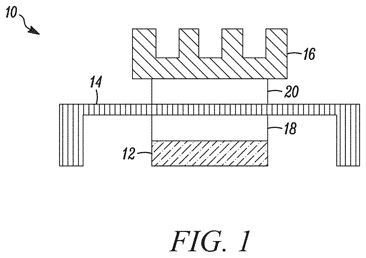
A typical electronics package structure 10 including thermal interface materials is illustrated in FIG. 1. The electronics package structure 10 illustratively includes a heat generating component, such as an electronic chip 12, and one or more heat dissipating components, such as a heat spreader 14, and a heat sink 16. Illustrative heat spreaders 14 and heat sinks comprise a metal, metal alloy, or metal-plated substrate, such as copper, copper alloy, aluminum, aluminum alloy, or nickel-plated copper. TIM materials, such as TIM 18 and TIM 20, provide a thermal connection between the heat generating component and the one or more heat dissipating components. Electronics package structure 10 includes a first TIM 18 connecting the electronic chip 12 and heat spreader 14. TIM 18 is typically referred to as a "TIM 1". Electronics package structure 10 includes a second TIM 20 connecting the heat spreader 14 and heat sink 16, TIM 20 is typically referred to as a "TIM 2". In another embodiment, electronics package structure 10 does not include a heat spreader 14, and a TIM (not shown) connects the electronic chip 12 directly to the heat sink 16. Such a TIM connecting the electronic chip 12 directly to the heat sink 16 is typically referred to as a TIM 1.5.
Traditional thermal interface materials include components such as gap pads. However, gap pads have certain disadvantages, such as inability to meet very small thickness requirements and being difficult to use in automated production.
Other thermal interface materials include gel products. Gel products may be automatically dispensed for large scale production, and can be formed to desired shapes and thicknesses. However, typical gel products have issues with dripping and cracking in temperature cycling tests, including that the product may potentially be more likely to fail in extreme cases.
Improvements in the foregoing are desired.
SUMMARY OF THE INVENTION
The present disclosure provides thermal interlace materials that are useful in transferring heat from heat generating electronic devices, such as computer chips, to heat dissipating structures, such as heat spreaders and heat sinks. The thermal interface material includes at least one silicone oil, at least one thermally conductive filler, and at least one addition inhibitor.
In one exemplary embodiment, a thermal interface material is provided. The thermal interface material includes at least one low molecular weight silicone oil having a weight (Mw) average molecular weight less than 50,000 Daltons; at least one thermally conductive filler; at least one addition catalyst; and at least one high molecular weight silicone oil, wherein the high molecular weight silicone oil comprises a vinyl functional silicone oil having a weight (Mw) average molecular weight of at least 60,000 Daltons. In a more particular embodiment, the at least one low molecular weight silicone oil comprises a first silicone oil and a second silicone oil, wherein the first silicone oil is a vinyl functional silicone oil and the second silicone oil is a hydride functional silicone oil.
In a more particular embodiment, the thermally conductive filler includes a first thermally conductive filler and a second thermally conductive filler, wherein the first thermally conductive filer is a metal oxide having a particle size greater than 1 micron and the second thermally conductive filler is a metal oxide have a particle size less than 1 micron. In another more particular embodiment, the thermally conductive filler includes a first thermally conductive filler, a second thermally conductive filler, and a third thermally conductive filler, wherein the first thermally conductive filler is a metal oxide having an average particle size greater than 10 microns, the second thermally conductive flier is a metal oxide having an average particle size between 1 micron and 10 microns, and the third thermally conductive filler is a metal oxide having an average particle size less than 1 micron.
In still another more particular embodiment, the thermal interface material comprises: from 2 wt % to 20 wt. % of the low molecular weight silicone oil; from 50 wt % to 95 wt % of the thermally conductive filler; and from 0.1 wt % to 5 wt % of the high molecular weight silicone oil. In still another more particular embodiment, the low molecular weight silicone oil comprises a first silicone oil and a second silicone oil, wherein the first silicone oil is a vinyl functional silicone oil and the second silicone oil is a hydride functional silicone oil.
In a more particular embodiment of any of the above embodiments, a thermal interface material is provided. The thermal interface material comprises: at least one silicone oil; at least one thermally conductive tiller; and at least one addition inhibitor, wherein the addition inhibitor comprises an alkynyl compound. In a still more particular embodiment, the addition inhibitor is selected from the group consisting of: a multivinyl functional polysiloxane, polydimethylsiloxane vinyl terminated in ethynyl cyclohexanol, 2-methyl-3-butyn-2-ol, and 3-methyl-1-pentyn-3-ol. In a more particular embodiment of any of the above embodiments, the at least one silicone oil comprises a first silicone oil and a second silicone oil, wherein the first silicone oil is a vinyl functional silicone oil and the second silicone oil is a hydride functional silicone oil.
In a more particular embodiment of any of the above embodiments, the thermally conductive filler includes a first thermally conductive filler and a second thermally conductive filler, wherein the first thermally conductive filer is a metal having a particle size greater than 1 micron and the second thermally conductive filler is a metal oxide having a particle size less than 1 micron. In a more particular embodiment of any of the above embodiments, a ratio of the first thermally conductive filler to the second thermally conductive filler is from 1.5:1 to 3:1.
In a more particular embodiment of any of the above embodiments, the thermal interface material comprises: from 2 wt. % to 20 wt. % of the silicone oil; from 0.1 wt. % to 5 wt. % of a silane coupling agent; from 50 wt. % to 95 wt. % of the thermally conductive filler; and from 0.01 wt. % to 5 wt. % of the addition inhibitor. In a more particular embodiment, the addition inhibitor is polydimethylsiloxane vinyl terminated in ethynyl cyclohexanol. In a more particular embodiment, the silicone oil comprises a first silicone oil and a second silicone oil, wherein the first silicone oil is a vinyl functional silicone oil and the second silicone oil is a hydride functional silicone oil.
In one exemplary embodiment, an electronic component is provided. The electronic component includes a heat sink; an electronic chip; a thermal interface material having a first surface layer and a second surface layer, the thermal interface material positioned between the heat sink and electronic chip, the thermal interface material including: at least one silicone oil; at least one thermally conductive filler; and at least one addition inhibitor, wherein the addition inhibitor comprises an alkynyl compound. In a more particular embodiment, the at least one silicone comprises at least one low molecular weight silicone oil and at least one high molecular weight silicone oil.
In a more particular embodiment, the at least one high molecular weight silicone oil comprises a vinyl functional silicone oil having a weight (Mw) average molecular weight of at least 60,000 Daltons. In another more particular embodiment, the first surface layer is in contact with a surface of the electronic chip and the second surface layer is in contact with the heat sink. In another more particular embodiment, the electronic component further comprises a heat spreader positioned between the heat sink and the electronic chip, wherein the first surface layer is in contact with a surface of the electronic chip and the second surface layer is in contact with the heat spreader. In a further more particular embodiment, the electronic component further comprises a heat spreader positioned between the heat sink and the electronic chip, wherein the first surface layer is in contact with a surface of the heat spreader and the second surface layer is in contact with the heat sink.
BRIEF DESCRIPTION OF THE DRAWINGS
The above-mentioned and other features and advantages of this disclosure, and the manner of attaining them, will become more apparent and the invention itself will be better understood by reference to the following description of embodiments of the invention taken in conjunction with the accompanying drawings, wherein:
FIG. 1 schematically illustrates a typical electronics package structure;
FIG. 2A is related to Example 1 and shows the sample formed from Example 1 before the thermal cycling test;
FIG. 2B is related to Example 1 and shows the sample formed from the comparative example before the thermal cycling test;
FIG. 3A is related to Example 1 and shows the sample formed from Example 1 after the thermal cycling test;
FIG. 3B is related to Example 1 and shows the sample formed from Example 1 after the thermal cycling test;
FIG. 4A is related to Example 2 and shows the sample formed from Comparative Example 2 before the thermal cycling test;
FIG. 4B is related to Example 2 and shows the sample formed from Example 2A before the thermal cycling test;
FIG. 4C is related to Example 2 and shows the sample formed from Example 2B before the thermal cycling test;
FIG. 5A is related to Example 2 and shows the sample formed from Comparative Example 2 after the thermal cycling test;
FIG. 5B is related to Example 2 and shows the sample formed from Example 2A after the thermal cycling test;
FIG. 5C is related to Example 2 and shows the sample formed from Example 2B after the thermal cycling test;
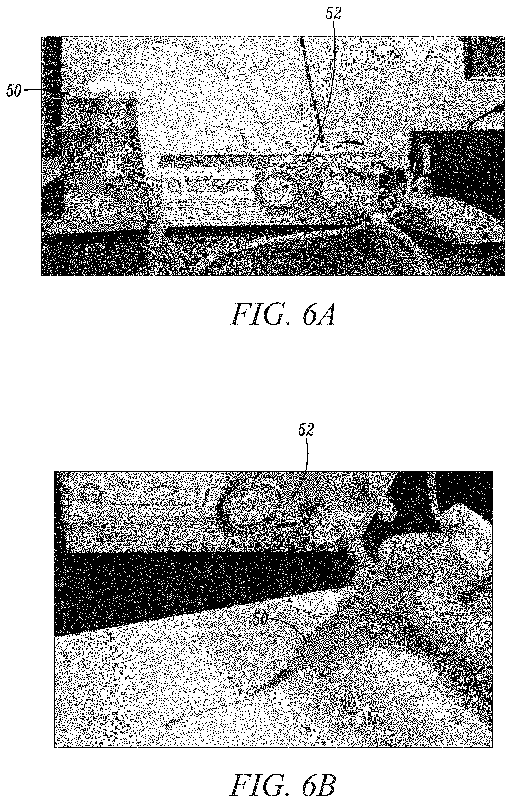
FIG. 6A shows a dispenser apparatus according to an embodiment of the present disclosure;
FIG. 6B shows the dispenser apparatus of FIG. 6A in operation; and
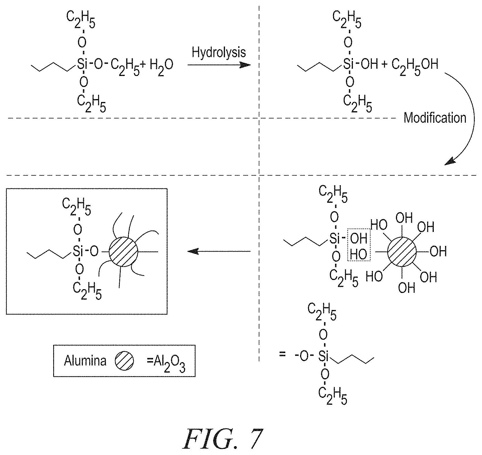
FIG. 7 is a schematic diagram showing the interaction of exemplary coupling agents with exemplary fillers.
Corresponding reference characters indicate corresponding parts throughout the several views. The exemplifications set out herein illustrate exemplary embodiments of the invention and such exemplifications are not to be construed as limiting the scope of the invention in any manner.
DETAILED DESCRIPTION
A. Thermal Interface Material
The present invention relates to thermal interface materials (TIMs) useful in transferring heat away from electronic components. In one exemplary embodiment, the TIM comprises at least one silicone oil, at least one catalyst, at least one thermally conductive filler, and at least one adhesion promoter including both amine and alkyl functional groups.
In some embodiments, the TIM may optionally include one or more of the following components: a silane coupling agent, an organic plasticizer, a surfactant, and a flux agent.
1. Silicone Oil
a. General Description
The present disclosure provides a matrix for a TIM material that includes at least one low molecular weight silicone oil and at least one high molecular weight silicone oil. The silicone oil includes one or more crosslinkable groups, such as vinyl, hydride, hydroxyl and acrylate functional groups, that are crosslinked by a catalyst. In one embodiment, one or more silicone oils include a first silicone oil and a second silicone oil, where the first silicone oil is a vinyl functional silicone oil and the second silicone oil is a hydride functional silicone oil. The silicone oil wets the thermally conductive filler and forms a dispensable fluid for the TIM.
In one exemplary embodiment, the silicone oil includes a silicone rubber such as the KE series products available from Shin-Etsu, such as SILBIONE.RTM. available from Bluestar, such as ELASTOSIL.RTM., SILPURAN.RTM., and SEMICOSIL.RTM. available from Wacker, such as Silopren.RTM. available from Momentive, such as Dow Corning.RTM., Silastic.RTM., XIAMETER.RTM., Syl-off.RTM. and SYLGARD.RTM. available from Dow Corning, such as SQUARE.RTM. available from Square Silicone, such as Andril.RTM. available from AB specialty Silicones. Other polysiloxanes are available from Wacker, Shin-etsu, Dowcoring, Momentive, Bluestar, RUNHE, AB Specialty Silicones, Gelest, and United Chemical Technologies.
b. Low Molecular Weight Silicone Oil
1. Vinyl Functional Silicone Oil
The TIM includes a low weight average molecular weight silicone oil as measured by gel permeation chromatography (GPC). Exemplary low molecular weight silicone oils may include a vinyl silicone oil having a general formula as shown below:
##STR00001##
An exemplary low molecular weight vinyl silicone oil may also include a small amount of platinum catalyst.
Vinyl functional silicone oils include an organo-silicone component with Si--CH.dbd.CH.sub.2 groups. Exemplary vinyl functional silicone oils include vinyl-terminated silicone oils and vinyl-grafted silicone oils in which the Si--CH.dbd.CH.sub.2 group is grafted onto the polymer chain, and combinations thereof.
Exemplary vinyl-terminated silicone oils include vinyl terminated polydimethylsiloxane, such as DMS-V00 (having a weight average molecular weight (M.sub.w) of 186 Daltons), DMS-V03 (having a M.sub.w of about 500 Daltons), DMS-V05 (having a M.sub.w of about 800 Daltons), DMS-V21 (having a M.sub.w of about 6,000 Daltons), DMS-V22 (having a M.sub.w of about 9400 Daltons), DMS-V25 (having a M.sub.w of about 17,200 Daltons), DMS-V25R (having a M.sub.w of about 17,200 Daltons), DMS-V35 (having a M.sub.w of about 49,500 Daltons), DMS-V35R (having a M.sub.w of about 49,500 Daltons), each available from Gelest, Inc. Exemplary vinyl-terminated silicone oils include vinyl terminated diphenylsiloxane-dimethylsiloxane copolymer, such as PDV-0325 (having a M.sub.w of about 15,500 Daltons), PDV-0331 (having a M.sub.w of about 27,000 Daltons), PDV-0525 (having a M.sub.w of about 14,000 Daltons), PDV-1625 (having a M.sub.w of about 9,500 Daltons), PDV-1631 (having a M.sub.w of about 19,000 Daltons), PDV-2331 (having a M.sub.w of about 12,500 Daltons), each available from Gelest, Inc. Exemplary vinyl-terminated silicone oils include vinyl terminated polyphenylmethylsiloxane, such as PMV-9925 (having a M.sub.w of about 2000-3000 Daltons) available from Gelest, Inc. Exemplary vinyl-terminated silicone oils include vinyl terminated diethylsiloxane-dimethylsiloxane copolymer, such as EDV-2025 (having a M.sub.w of about 16,500-19,000 Daltons) available from Gelest, Inc.
Exemplary vinyl-grafted silicone oils include vinylmethylsiloxane homopolymers, such as VMS-005 (having a M.sub.w of about 258-431 Dalton), VMS-T11 (having a M.sub.w of about 1000-1500 Daltons), both available from Gelest, Inc. Exemplary vinyl-grafted silicone oils include vinylmethylsiloxane-dimethylsiloxane copolymers, such as trimethylsiloxyl terminated silicone oils, silanol terminated silicone oils, and vinyl terminated silicone oils.
In one exemplary embodiment, the vinyl-grafted silicone oil is a vinylmethylsiloxane terpolymers, including a vinylmethylsiloxane-octylmethylsiloxane-dimethylsiloxane terpolymer, such as VAT-4325 (having a M.sub.w of about 10,000-12,000 Daltons), or a vinylmethylsiloxane-methoxypolyethylenoxypropylmethylsiloxane-dimethylsil- oxane terpolymer, such as VBT-1323 (having a M of about 8,000-12,000 Daltons), or a vinylmethylsiloxane-phenylmethylsiloxane-dimethylsiloxane (having a M.sub.w of about 2,500-3,000 Daltons); each available from Gelest, Inc.
In one exemplary embodiment, the vinyl-functional silicone oil comprises a vinyl T resin or a vinyl Q resin.
In one exemplary embodiment, the silicone oil is a vinyl functional oil, such as RSI-V1303, RH-V1301 from RUNHE, such as Andril.RTM. VS 200, Andril.RTM. VS 1000 from AB Specialty Silicones.
2. Hydride Functional Silicone Oil
Another exemplary low molecular weight silicone oil may include a hydrosilicone oil having a general formula as shown below:
##STR00002##
In one exemplary embodiment, the silicone oil comprises a hydride functional silicone oil having an organo-silicone component and Si--H groups. Exemplary hydride functional silicone oils include hydride-terminated silicone oils and hydride-grafted silicone oils in which the Si--H group is grafted onto the polymer chain, and combinations thereof.
In one exemplary embodiment, the hydride-terminated silicone oil is a hydride terminated polydimethylsiloxane such as DMS-H03 (having a M.sub.w of about 400-500 Daltons), DMS-H11 (having a M.sub.w of about 1,0004,100 Daltons), DMS-H21 (having a M.sub.w of about 6,000 Daltons), DMS-H25 (having a M.sub.w of about 17,200 Daltons), or DMS-H31 (having a M.sub.w of about 28,000 Daltons), each available from Gelest, Inc. In one exemplary embodiment, the hydride-terminated silicone oil is a methylhydrosiloxane-dimethylsiloxane copolymer, such as a trimethylsiloxyl terminated or hydride terminated. Exemplary trimethylsiloxyl terminated copolymers include HMS-031 (having a M.sub.w of about 1,900-2,000 Daltons), HMS-071 (having a M.sub.w of about 1,900-2,000 Daltons), HMS-082 (having a M of about 5,500-6,500 Daltons), HMS-151 (having a M.sub.w of about 1,900-2,000 Daltons), HMS-301 (having a M.sub.w of about 1,900-2,000 Daltons), HMS-501 (having a M.sub.w of about 900-1200 Daltons); exemplary hydride terminated copolymers include HMS-H271 (having a M.sub.w of about 2,000-2,600 Daltons); each of which is available from Gelest, Inc. In one exemplary embodiment, the hydride-grafted silicone oil is polymethylhydrosiloxane with trimethylsiloxyl terminated, such as HMS-991 (having a M.sub.w of about 1,400-1,800 Daltons), HMS-992 (having a M.sub.w of about 1,800-2,100 Daltons), HMS-993 (having a M.sub.w of about 2,100-2,400 Daltons), each available from Gelest, Inc.
Exemplary low molecular weight silicone oils may have a weight (M.sub.w) average molecular weight as little as 50 Daltons, 500 Daltons, 1000 Daltons, as great as 5000 Daltons, 10,000 Daltons, 50,000 Daltons, or within any range defined between any two of the foregoing values.
Exemplary low molecular weight silicone oils may have a kinematic viscosity as little as 0.5 cSt, 5 cSt, 100 cSt, as great as 5,000 cSt, 10,000 at, 50,000 cSt, or within any range defined between any two of the foregoing values as measured according to ASTM D445.
The TIM comprises one or more low molecular weight silicone oils in an amount as little as 0.1 wt %, 0.5 wt. %, 0.67 wt %, 1 wt. %, as great as 3 wt. %, 5 wt. %, 10 wt. %, 20 wt %, or within any range defined between any two of the foregoing values, based on the total weight of the TIM, such as 0.1 wt. % to 15 wt. %, 0.1 wt. % to 3 wt. %, or 0.67 wt. % to 10 wt. %.
c. High Molecular Weight Silicone Oil
The TIM includes a high molecular weight silicone oil as measured by gel permeation chromatography (GPC). Exemplary high molecular weight silicone oils may include a vinyl silicone oil having a general formula as shown below, similar to the low molecular weight silicone oils described above:
##STR00003##
Vinyl functional silicone oils include an organo-silicone component with Si-CH.dbd.CH.sub.2 groups. Exemplary vinyl functional silicone oils include vinyl-terminated silicone oils and vinyl-grafted silicone oils in which the Si--CH.dbd.CH.sub.2 group is grafted onto the polymer chain, and combinations thereof.
Exemplary vinyl-terminated silicone oils include vinyl terminated polydimethylsiloxane, such as DMS-V41 (having a M.sub.w of about 62,700 Daltons), DMS-V42 (having a M.sub.w of about 72,000 Daltons), DMS-V46 (having a M.sub.w of about 117,000 Daltons), DMS-V51 (having a M.sub.w of about 140,000 Daltons), and DMS-V52 (having a M.sub.w of about 155,000 Daltons), each available from Gelest, Inc.
Exemplary vinyl-grafted silicone oils include vinylmethylsiloxane-dimethylsiloxane copolymers, such as trimethylsiloxyl terminated silicone oils, silanol terminated silicone oils, and vinyl terminated silicone oils.
In one exemplary embodiment, the vinyl-grafted silicone oil is a vinylmethylsiloxane terpolymers. In one exemplary embodiment, the vinyl-functional silicone oil comprises a vinyl T resin or a vinyl Q resin.
Another exemplary high molecular weight silicone oil may include a hydride functional silicone oil having an organo-silicone component and Si--H groups. Exemplary hydride functional silicone oils include hydride-terminated silicone oils, hydride-grafted silicone oils in which the Si--H group is grafted onto the polymer chain, and combinations thereof.
In one exemplary embodiment, the hydride-terminated silicone oil is a hydride terminated polydimethylsiloxane such as DMS-H41 (having a M.sub.w of about 62,700 Daltons), available from Gelest, Inc. In one exemplary embodiment, the hydride-terminated silicone oil is a methylhydrosiloxane-dimethylsiloxane copolymer, such as a trimethylsiloxyl terminated or hydride terminated. Exemplary trimethylsiloxyl terminated copolymers include HMS-064 (having a M.sub.w of about 60,000-65,000 Daltons), available from Gelest, Inc.
Exemplary low molecular weight silicone oils may have a weight (M.sub.w) average molecular weight as little as 60,000 Daltons, 70,000 Daltons, 100,000 Daltons, as great as 1,000,000 Daltons, 10,000,000 Daltons, 100,000,000 Daltons, or within any range defined between any two of the foregoing values.
Exemplary high molecular weight silicone oils may have a kinematic viscosity as little as 10,000 cSt, 20,000 cSt, 100,000 cSt, as great as 1,000,000 cSt, 10,000,000 cSt, 100,000,000 cSt, or within any range defined between any two of the foregoing values as measured according to ASTM D445. In one exemplary embodiment, an exemplary high molecular weight silicone oil is a high molecular weight vinyl silicone oil having a kinematic viscosity of 2,000,000 cSt.
The TIM may comprise one or more high molecular weight silicone oils in an amount as little as 0.01 wt %, 0.1 wt. %, 0.25 wt. %, 0.5 wt. %, 0.67 wt. %, 0.75 wt. %, as great as 1 wt %, 1.5 wt. %, 2 wt. %, 5 wt. %, or within any range defined between any two of the foregoing values, based on the total weight of the TIM, such as 0.1 wt. % to 5 wt. %, 0.1 wt. % to 1 wt. %, or 0.25 wt. % to 0.67 wt %. In one exemplary embodiment, the TIM includes a high molecular weight silicone oil in the amount of about 0.6 wt. %. In another exemplary embodiment, the TIM includes a high molecular weight silicone oil in the amount of about 2.68 wt. %.
2. Catalyst
The TIM further includes one or more catalyst for catalyzing the addition reaction. Exemplary catalysts comprise platinum containing materials and rhodium containing materials. Exemplary platinum containing catalysts may have the general formula shown below:
##STR00004##
Exemplary platinum contain catalysts include: Platinum cyclovinylmethylsiloxane complex (Ashby Karstedt Catalyst), Platinum carbonyl cyclovinylmethylsiloxane complex (Ossko catalyst), Platinum divinyltetramethyldisiloxane dimethyl fumarate complex, Platinum divinyltetramethyldisiloxane dimethyl maleate complex and the like. Exemplary of Platinum carbonyl cyclovinylmethylsiloxane complexes include SIP6829.2, exemplary of Platinum divinyltetramethyldisiloxane complex include SIP6830.3 and SIP6831.2, exemplary of platinum cyclovinylmethylsiloxane complex include SIP6833.2, all available from Gelest, Inc. Further exemplary platinum containing material catalysts include Catalyst OL available from Wacker Chemie AG, and PC065, PC072, PC073, PC074, PC075, PC076, PC085, PC086, PC087, PC088 available from United Chemical Technologies Inc.
Exemplary rhodium containing materials include Tris(dibutylsulfide)Rhodium trichloride with product code INRH078, available from Gelest, Inc.
Without wishing to be held to any particular theory it is believed that the platinum catalyst reacts with a vinyl silicone oil and a hydrosilicone oil as shown below.
##STR00005##
The TIM may comprise the one or more catalyst in an amount as little as 5 ppm, 10 ppm, 15 ppm, 20 ppm, as great as 25 ppm, 30 ppm, 40 ppm, 50 ppm, 100 ppm, 200 ppm, 500 ppm, 1000 ppm, or within any range defined between any two of the foregoing values, based on the total weight of the silicone oil, such as 10 ppm to 30 ppm, 20 ppm to 100 ppm, or 5 ppm to 500 ppm.
In one exemplary embodiment, the catalyst is provided as a mixture with one or more of the silicone oils. In one exemplary embodiment, the platinum containing material catalyst is combined to a functional silicone oil, such as KE-1012-A, KE-1031-A, KE-109E-A, KE-1051J-A, KE-1800T-A, KE1204A, KE1218A available from Shin-Etsu, such as SILBIONE.RTM. RT Gel 4725 SLID A available from Bluestar, such as SilGel.RTM. 612 A, ELASTOSIL.RTM. LR 3153A, ELASTOSIL.RTM. LR 3003A, ELASTOSIL.RTM. LR 3005A, SEMICOSIL.RTM. 981A, SEMICOSIL.RTM. 927A, SEMICOSIL.RTM. 205A, SEMICOSIL.RTM. 9212A, SILPURAN.RTM. 2440 available from Wacker, such as Silopren.RTM. LSR 2010A available from Momentive, such as XIAMETER.RTM. RBL-9200 A, XIAMETER.RTM. R812004 A, XIAMETER.RTM. RBL-9050 A, XIAMETER.RTM. RBL-1552 A, Silastic.RTM. FL 30-9201 A, Silastic.RTM. 9202 A, Silastic.RTM. 9204 A, Silastic.RTM. 9206 A, SYLGARD.RTM. 184A, Dow Corning.RTM. QP-1 A, Dow Corning.RTM. C6 A, Dow Corning.RTM. CV9204 A available from Dow Corning.
The TIM may comprise a catalyst in an amount as little as 0.01 wt %, 0.1 wt. %, 0.2 wt. %, as great as 0.3 wt %, 0.4 wt. %, 0.5 wt. %, or within any range defined between any two of the foregoing values, based on the total weight of the TIM. In one exemplary embodiment, the TIM includes a catalyst in the amount of about 0.04 wt %. In another exemplary embodiment, the TIM includes a catalyst in the amount of about 0.4 wt. %.
In another embodiment, the platinum containing material catalyst is combined to a high molecular weight vinyl functional silicone oil.
3. Thermally Conductive Filler
The TIM includes one or more thermally conductive fillers. Exemplary thermally conductive fillers include metals, alloys, nonmetals, metal oxides and ceramics, and combinations thereof. The metals include, but are not limited to, aluminum, copper, silver, zinc, nickel, tin, indium, and lead. The nonmetal include, but are not limited to, carbon, graphite, carbon nanotubes, carbon fibers, graphenes, boron nitride and silicon nitride. The metal oxide or ceramics include but not limited to alumina (aluminum oxide), aluminum nitride, boron nitride, zinc oxide, and tin oxide.
The TIM may comprise the one or more thermally conductive fillers in an amount as little as 10 wt. %, 20 wt %, 25 wt. %, 50 wt. %, as great as 75 wt. %, 80 wt %, 85 wt. %, 90 wt. %, 95 wt. %, 97 wt. %, or within any range defined between any two of the foregoing values, based on the total weight of the TIM, such as 10 wt. % to 95 wt %, 50 wt. % to 95 wt. %, or 85 wt % to 97 wt %.
Exemplary thermally conductive fillers may have an average particle size of as little as 0.1 microns, 1 micron, 10 microns, as great as 50 microns, 75 microns, 100 microns or within any range defined between any two of the foregoing values.
In one exemplary embodiment, the TIM may include a first thermally conductive filler and a second thermally conductive filler, wherein the first thermally conductive filer has an average particle size greater than 1 micron and the second thermally conductive filler has an average particle size less than 1 micron. In a more particular embodiment, a ratio of the first thermally conductive filler to the second thermally conductive filler may be as little as 1:5, 1:4, 1:3, 1:2, as great as 1:1, 1,5:1, 2:1, 3:1, 4:1, 5:1, or within any range defined between any two of the foregoing values, such as 1:5 to 5:1 1:1 to 3:1, or 1.5:1 to 3:1.
In one exemplary embodiment, the TIM may include a first thermally conductive filler, a second thermally conductive filler, and a third thermally conductive filler, wherein the first thermally conductive filer has a particle size greater than 10 micron, the second thermally conductive filler has an average particle size as little as 1 micron, 2 microns, 4 microns, as great as 6 microns, 8 microns, 10 microns, or within any range defined therebetween, and the third thermally conductive filler has an average particle size less than 1 micron.
In one exemplary embodiment, the TIM includes a first thermally conductive filler in the amount of as little as 30 wt. %, 35 wt. %, 40 wt %, as great as 45 wt. %, 50 wt. %, 60 wt % or within any range defined between any two of the foregoing values with respect to the total TIM composition. The first thermally conductive filler has an average particle size of as little as 30 microns. 35 microns, 40 microns, as great as 45 microns, 50 microns, 60 microns, or within any range defined between any two of the foregoing values. The exemplary TIM further includes a second thermally conductive filler in the amount of as little as 5 wt. %, 10 wt %, 15 wt. %, as great as 25 wt. %, 30 wt. %, 40 wt % or within any range defined between any two of the foregoing values with respect to the total TIM composition. The second thermally conductive filler has an average particle size of as little as 1 micron, 3, microns. 5 microns, as great as 10 microns, 15 microns, 20 microns, or within any range defined between any two of the foregoing values. The exemplary TIM further includes a third thermally conductive filler in the amount of as little as 5 wt. %, 10 wt. %, 15 wt. %, as great as 25 wt. %, 30 wt %, 40 wt % or within any range defined between any two of the foregoing values with respect to the total TIM composition. The third thermally conductive filler has an average particle size of as little as 0.1 microns, 0.3, microns. 0.5 microns, as great as 1 micron, 1.5 microns, 2 microns, or within any range defined between any two of the foregoing values.
In one exemplary embodiment, the TIM includes a first thermally conductive filler in the amount of as little as 5 wt. %, 10 wt. %, 15 wt. %, as great as 25 wt. %, 30 wt. %, 40 wt % or within any range defined between any two of the foregoing values with respect to the total TIM composition. The first thermally conductive filler having an average particle size of as little as 30 microns. 35 microns, 40 microns, as great as 45 microns, 50 microns, 60 microns, or within any range defined between any two of the foregoing values. The exemplary TIM further includes a second thermally conductive filler in the amount of as little as 30 wt. %, 35 wt. %, 40 wt. %, as great as 45 wt. %, 50 wt. %, 60 wt % or within any range defined between any two of the foregoing values with respect to the total TIM composition. The second thermally conductive filler having an average particle size of as little as 1 micron, 3, microns. 5 microns, as great as 10 microns, 15 microns, 20 microns, or within any range defined between any two of the foregoing values. The exemplary TIM further includes a third thermally conductive filler in the amount of as little as 5 wt. %, 10 wt. %, 15 wt. %, as great as 25 wt. %, 30 wt. %, 40 wt % or within any range defined between any two of the foregoing values with respect to the total TIM composition. The third thermally conductive filler having an average particle size of as little as 0.1 microns, 0.3, microns. 0.5 microns, as great as 1 micron, 1.5 microns. 2 microns, or within any range defined between any two of the foregoing values.
Exemplary thermal conductive fillers include alumina oxide and zinc oxide.
4. Addition Inhibitor
The TIM comprises one or more addition inhibitors for inhibiting or limiting crosslinking of the silicone oils. The addition inhibitors includes at least one alkynyl compound, and optionally, the addition inhibitor further includes a multi-vinyl functional polysiloxane.
Exemplary addition inhibitors include acetylenic alcohols such as 1-ethynyl-1-cyclohexanol, 2-methyl-3-butyn-2-ol, 2-phenyl-3-butyn-2-ol, 2-ethynyl-isopropanol, 2-ethynyl-butane-2-ol, and 3,5-dimethyl-1-hexyn-3-ol; silylated acetylenic alcohols such as trimethyl (3,5-dimethyl-1-hexyn-3-oxy)silane, dimethyl-bis-(3-methyl-1-butyn-oxy)silane, methylvinylbis(3-methyl-1-butyn-3-oxy)silane, and ((1,1-dimethyl-2-propynyl)oxy)trimethylsilane; unsaturated carboxylic esters such as diallyl maleate, dimethyl maleate, diethyl fumarate, diallyl fumarate, and bis-2-methoxy-1-methylethylmaleate, mono-octylmaleate, mono-isooctylmaleate, mono-allyl maleate, mono-methyl maleate, mono-ethyl fumarate, mono-allyl fumarate, 2-methoxy-1-methylethylmaleate; fumarate/alcohol mixtures, such as mixtures where the alcohol is selected from benzyl alcohol or 1-octanol and ethenyl cyclohexyl-1-ol; conjugated ene-ynes such as 2-isobutyl-1-butene-3-yne, 3,5-dimethyl-3-hexene-1-yne, 3-methyl-3-pentene-1-yne, 3-methyl-3-hexene-1-yne, 1-ethynylcyclohexene, 3-ethyl-3-butene-1-yne, and 3-phenyl-3-butene-1-yne; vinylcyclosiloxanes such as 1,3,5,7-tetramethyl-1,3,5,7-tetravinylcyclotetrasiloxane, and mixtures of conjugated ene-yne and vinylcyclosiloxane. In one exemplary embodiment, the addition inhibitor is selected from 2-methyl-3-butyn-2-ol or 3-methyl-1-pentyn-3-ol.
In some exemplary embodiments, the addition inhibitor further includes a multi-vinyl functional polysiloxane. An exemplary multi-vinyl functional polysiloxane is a vinyl terminated polydimethylsiloxane in ethynyl cyclohexanol, such as Pt Inhibitor 88 available from Wacker Chemie AG. Without wishing to be held to any particular theory it is believed that the platinum catalyst forms a complex with ethynyl cyclohexanol and vinyl terminated polydimethylsiloxane as shown below.
##STR00006##
The formation of the complex is believed to decrease the catalyst activity in room temperature, and thus maintaining the dispensability and wettability of the TIM. At the higher temperatures of the curing step, the Pt is released from the complex and help the hydrosilylation of vinyl functional silicone oil and hydride functional silicone oil, provides greater control over the "crosslinking".
In some exemplary embodiments, the TIM may comprise the one or more addition inhibitors in an amount as little as 0.01 wt. %, 0.02 wt %, 0.05 wt. %, 0.1 wt. %, 0.15 wt. %, as great as 0.2 wt. %, 0.25 wt. %, 0.3 wt. %, 0.5 wt. %, 1 wt. %, 3 wt %, 5 wt. %, or within any range defined between any two of the foregoing values, based on the total weight of the TIM, such as 0.01 wt. % to 1 wt. %, 0.01 wt. % to 0.5 wt. %, or 0.05 wt. % to 0.2 wt. %. In one exemplary embodiment, the TIM includes an addition inhibitor in the amount of 0.1 wt %. In another exemplary embodiment, the TIM includes an addition inhibitor in the amount of 0.13 wt. %.
Without wishing to be held to any particular theory, it is believed that, in the absence of an addition inhibitor, the vinyl functional silicone oil reacts with the hydride functional silicone oil very quickly based on the addition hydrosilylation mechanism to form a solid phase that cannot be automatically dispensed by typical methods.
In one exemplary embodiment, the addition inhibitor is combined to functional silicone oils, such as KE-1056, KE-1151, KE-1820, KE-1825, KE-1830, KE-1831, KE-1833, KE-1842, KE-1884, KE-1885, KE-1886, FE-57, FE-61 available from Shin-Etsu, such as Syl-off.RTM. 7395, Syl-off.RTM. 7610, Syl-off.RTM. 7817, Syl-off.RTM. 7612, Syl-off.RTM. 7780 available from Dow Corning.
5. Optional Components
In some embodiments, the TIM may optionally include one or more of the following components: a silane coupling agent, an organic plasticizer, a surfactant, and a flux agent.
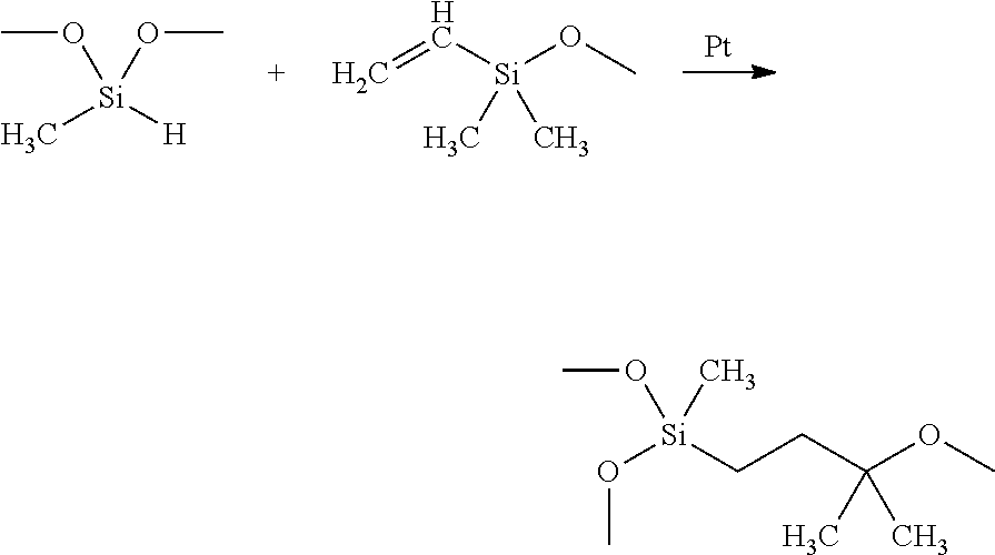
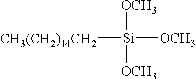
In some exemplary embodiments, the TIM comprises one or more coupling agents. Exemplary coupling agents include silane coupling agents with general formula Y--(CH.sub.2).sub.n--Si--X.sub.3, wherein Y is organofunctional group, X is hydrolysable group. Organofunctional group Y includes alkyl, glycidoxy, acryloxyl, methylacryloxyl, amine. Hydrolysable group X includes alkyloxy, acetoxy. In some exemplary embodiments, the silane coupling agent includes alkyltrialkoxysilanes. Exemplary alkytrialkoxy silane comprise decyltrimethoxylsilane, undecyltrimethoxylsilane, hexadecyltrimethoxysilane, octadecyltrimethoxysilane. In one exemplary embodiment, the TIM includes hexadecyltrimethoxysilane as the coupling agent's shown in the formula below.
##STR00007##
Exemplary coupling agents interact with exemplary fillers as shown in the example reaction in FIG. 7. Alumina is the representative filler used in the reaction below; however, other alternative fillers may be used. As shown, the coupling agent is added to water and undergoes hydrolysis to remove an ethoxide group. The products then undergo a modification reaction where water is removed and the coupling agent and alumina are bonded together.
In some exemplary embodiments, the TIM may comprise the one or more coupling agents in an amount as little as 0.1 wt. %, 0.25 wt. %, 0.5 wt %, 0.67 wt. %, 0.75 wt. %, as great as 1 wt. %, 1.5 wt. %, 2 wt. %, 5 wt. %, 10 wt. %, or within any range defined between any two of the foregoing values, based on the total weight of the TIM, such as 0.1 wt. % to 10 wt. %, 0.1 wt. % to 1 wt. %, or 0.25 wt. % to 0.67 wt %. In one exemplary embodiment, the TIM includes a coupling agent in the amount of 0.4 wt. %.
In some exemplary embodiments, the TIM comprises one or more organic plasticizers. Exemplary organic plasticizers include phthalate-based plasticizers such as Bis(2-ethylhexyl) phthalate (DEHP), Di-n-butyl phthalate (DnBP, DBP), Dioctyl phthalate (DOP or DnOP), Diethyl phthalate (DEP), Diisobutyl phthalate (DIBP), Diisodecyl phthalate (DIDP), Diisononyl phthalate (DINP), and Butyl benzyl phthalate (BBzP).
In some exemplary embodiments, the TIM may comprise the one or more organic plasticizers in an amount as little as 0.01%, 0.1 wt. %, 0.25 wt %, 0.5 wt %, 0.67 wt. %, 0.75 wt %, as great as 1 wt. %, 1.5 wt. %, 2 wt. %, 5 wt %, 10 wt. %, or within any range defined between any two of the foregoing values, based on the total weight of the TIM, such as 0.01 wt. % to 10 wt. %, 0.1 wt. % to 1 wt %, or 0.25 wt. % to 0.67 wt. %.
In some exemplary embodiments, the TIM comprises one or more surfactants. Exemplary surfactants include silicone based surface additives, such as the BYK surfactants available from BYK Chemie GmbH, including BYK-307, BYK-306, and BYK-222.
In some exemplary embodiments, the TIM may comprise the one or more surfactants in an amount as little as 0.01%, 0.1 wt. %, 0.25 wt. %, 0.5 wt. %, 0.87 wt. %, 0.75 wt %, as great as 1 wt. %, 1.5 wt %, 2 wt. %, 5 wt. %, 10 wt. %, or within any range defined between any two of the foregoing values, based on the total weight of the TIM, such as 0.1 wt % to 10 wt. %, 0.1 wt % to 1 wt %, or 0.25 wt. % to 0.67 wt. %.
In some exemplary embodiments, the TIM comprises one or more flux agents. Exemplary flux agents include fumed silica.
In some exemplary embodiments, the TIM may comprise the one or more flux agents in an amount as little as 0.1 wt. %, 0.25 wt. %, 0.5 wt. %, 0.67 wt. %, 0.75 wt. %, as great as 1 wt %, 1.5 wt. %, 2 wt. %, 5 wt. %, 10 wt. %, or within any range defined between any two of the foregoing values, based on the total weight of the TIM, such as 0.1 wt % to 10 wt. %, 0.1 wt. % to 1 wt. %, or 015 wt % to 0.67 wt. %.
6. Exemplary Formulations of the Thermal Interface Material
In a first non-limiting illustrative embodiment, the TIM includes about 2 wt. % to about 20 wt % silicone oil, about 0.1 wt. % to about 5 wt. % coupling agent, about 50 wt. % to about 95 wt. % thermally conductive filler, about 0.1 wt. % to about 5 wt. % addition inhibitor, and about 0.1 wt. % to about 5 wt. % addition catalyst.
In a second non-limiting illustrative embodiment, the TIM includes about 2 wt. % to about 10 wt. % of a first low molecular silicone oil, about 2 wt. % to about 10 wt. % of a second low molecular silicone oil, about 0.1 wt. % to about 5 wt. % of a high molecular weight silicone oil, about 0.1 wt. % to about 5 wt. % of a coupling agent, about 25 wt. % to about 50 wt. % of a first thermally conductive filler, about 25 wt % to about 50 wt. % of a second thermally conductive filler, about 25 wt. % to about 50 wt. % of a third thermally conductive filler, about 0.1 wt. % to about 5 wt. % addition inhibitor, and about 0.1 wt. % to about 5 wt. % addition catalyst.
7. Exemplary Properties of the Thermal Interface Material
In some exemplary embodiments, a thermal interface material as described above has excellent resistance to highly-accelerated stress testing (HAST). HAST testing is typically understood to relate to the resistance of the thermal interface material to humidity and temperature on the thermal performance of the thermal interface material. An exemplary HAST test standard is JESD22-A110-B. In one particular embodiment, the thermal interface material shows no dripping when placed between a glass and exemplary copper heat sink at in a vertically oriented 1.6 mm gap and subjected to 10000 thermal cycles between -55.degree. C. and +125.degree. C. for over one week. In other embodiments, the thermal interface material shows little to no cracking following the thermal cycling test.
In some exemplary embodiments, a thermal interface material as described above has excellent resistance to temperature cycling. Temperature cycling is typically understood to relate to the resistance of the thermal interface material to extremes of high and low temperatures, as well as its ability to withstand cyclical thermal stresses. An exemplary temperature cycling test standard is JESD22-A104-B. In one particular embodiment, the thermal interface material shows no dripping when placed between a glass an exemplary copper heat sink at in a vertically oriented 1.6 mm gap and subjected to 10000 thermal cycles between -55.degree. C. and +125.degree. C. over one week. In other embodiments, the thermal interface material shows little to no cracking following the temperature cycling test.
In some exemplary embodiments, a thermal interface material as described above has the thermal conductivity at least 1 W/mK. An exemplary thermal conductivity test method standard is ASTM D5470. In one exemplary amendment, a thermal interface material as described above has the thermal conductivity of about 4 W/mK. In another exemplary embodiment, a thermal interface material as described above has the thermal conductivity of about 2 W/mK.
In some exemplary embodiments, a thermal interface material as described above has the viscosity in the range of 10 Pas to 100,000 Pas, or more particularly in the range of 100 Pas to 10,000 Pas at room temperature. An exemplary viscosity test method standard is DIN 53018. In one particular embodiment, the viscosity is tested by Brookfield Rheometer with shear rate 2 s.sup.-1.
As applied, a thermal interface material can have a varied thickness as measured by a micrometer. In some exemplary embodiments, a thermal interface material as described above has a thickness of as little as 0.05 mm, 0.5 mm, 1 mm, as great as 3 mm, 5 mm, 7 mm, 10 mm or within any range defined between any two of the foregoing values, such as from 0.05 mm to 5 mm.
In some exemplary embodiments, a thermal interface material as described above is compressible at a given temperature when cured. In one exemplary embodiment, the thermal interface material is compressible by at least 10% at a temperature of about 25.degree. C.
In some exemplary embodiments, a thermal interface material as described above has the dispense rate in the range of 1 g/min to 1000 g/min, or more particularly in the range of 10 g/min to 100 g/min. In one particular embodiment, the dispense rate is tested under 0.6 MPa pressure with a 10 ml syringe having a 0.1 inch diameter dispense header opening.
B. Methods of Forming a Thermal Interface Material
In some exemplary embodiments, the TIM is prepared by combining the individual components in a heated mixer and blending the composition together. The blended composition may then be applied directly to the substrate without baking.
C. Applications Utilizing the Thermal Interface Material
Referring again to FIG. 1, in some exemplary embodiments, the thermal interface material is positioned as a TIM 1 between an electronic component 12 and a heat spreader 14, as indicated by TIM 18. In some exemplary embodiments, the thermal interface material is positioned as a TIM 2 between a heat spreader 14 and a heat sink 16, as indicated by TIM 20. In some exemplary embodiments, the thermal interface material is positioned as a TIM 1.5 (not shown) between an electronic component 12 and a heat sink 16.
EXAMPLES
Example 1
A thermal interface material was prepared according to the formulation provided in Table 1.
TABLE-US-00001 TABLE 1 Formulations (wt. %) for Example 1 Component Wt. % Low MW silicone oil A 4.75 Low MW silicone oil B 4.75 Silane coupling agent 0.5 Thermal conductive filler A 60 Thermal conductive filler B 30 Addition inhibitor 0.1
Low molecular weight (MW) silicone oil A was a low molecular weight liquid silicone rubber comprising vinyl functional group. The molecular weight of the low MW silicone oil was below 50,000 Daltons and further included a platinum catalyst. Low MW silicone oil B is a liquid silicone rubber comprising hydride functional group and has a molecular weight below 58,000 Daltons. The silane coupling agent was hexadecyltrimethoxysilane. Thermal conductive filler A was aluminum particles having a particle diameter between 1 and 10 microns. Thermal conductive filler B was zinc oxide particles having a particle diameter less than 1 micron. The addition inhibitor was Pt Inhibitor 88 available from Wacker Chemie AG.
To prepare the formulation of Example 1, the silicone oil, silane coupling agent, and addition inhibitor were combined and blended with a speed mixer. The thermally conductive fillers were then added, and the mixture was blended again.
A GEL 30 Thermally Conductive Dispensable Gel from Parker Chomerics was obtained for use a comparative example. GEL 30 includes a partially cross-linked silicone rubber and alumina.
The formulation of Example 1 and the comparative example were each sandwiched between a glass and an exemplary heat sink in a vertically oriented 1.6 mm gap and subjected to thermal cycling between -55.degree. C. and +125.degree. C. for one week.
FIG. 2A shows the sample formed from Example 1 before the thermal cycling test and FIG. 2B shows the sample formed from the GEL 30 comparative example before the thermal cycling test. FIG. 3A shows the sample formed from Example 1 after the thermal cycling test and FIG. 3B shows the sample formed from the GEL 30 comparative example after the thermal cycling test.
As shown in FIG. 3A, the sample formed from Example 1 showed no dripping, as indicated by the sample maintaining its original vertical position between the glass and substrate during the test. In contrast, the sample formed from the comparative example showed significant dripping as indicated by the movement downward between FIGS. 2B and 3B.
In addition, FIG. 3A showed limited cracking of the sample formed from Example 1 due to the thermal cycling test. In contrast, FIG. 3B showed significantly more cracking in the comparative example.
Example 2
A thermal interface material was prepared according to the formulation provided in Table 2.
TABLE-US-00002 TABLE 2 Formulations (wt. %) for Example 2 Comp. Ex. 2 Ex. 2A Ex. 2B Ex. 2C Component (wt. %) (wt. %) (wt. %) (wt. %) Low MW 5 4.2 4.6 3.14 silicone oil A Low MW 5 4.4 4.6 3.3 silicone oil B High MW 0.6 0.9 Silicone Oil Silane 0.5 0.5 0.5 0.4 coupling agent Thermal 60 60 60 conductive filler A Thermal 30 30 30 conductive filler B Thermal 43.8 conductive filler C Thermal 21.9 conductive filler D Thermal 26.3 conductive filler E Addition 0.1 0.1 0.1 inhibitor Addition 0.2 0.2 0.16 Catalyst
Low molecular weight (MW) silicone oil A was a low molecular weight liquid silicone rubber comprising vinyl functional group. The molecular weight of the low MW silicone oil A was below 50,000 Daltons and further Included a platinum catalyst. Low MW silicone oil B was a low molecular weight liquid silicone rubber comprising hydride functional group. The molecular weight of the low MW silicone oil B was below 50,000 Daltons. High MW silicone oil had the molecular weight higher than 60,000 Daltons. The silane coupling agent was hexadecyltrimethoxysilane. Thermal conductive filler A was aluminum oxide particles having a particle diameter between 1 and 10 microns. Thermal conductive filler B was aluminum oxide particles having a particle diameter less than 1 micron. The addition inhibitor was Pt Inhibitor 88 available from Wacker Chemie AG.
After one of Comp. Ex. 2, Ex. 2A, 2B, or 2C are prepared, the prepared mixture is inserted into and sealed in a syringe 50 as shown in FIGS. 6A, 6B. Syringe 50 is connected to an automatic dispenser tool 52. The mixtures can be purged out of syringe 50 by air pressure generated by dispenser tool 52. Dispenser tool 52 also controls the orifice diameter. In effect, dispenser tool 52 controls the dispense rate of the mixtures from syringe 50 by varying the two parameters--orifice diameter and air pressure. In one embodiment, the formulation is dispensed from syringe 50 with no tip attachment at 10 cubic centimeters under a compression of 90 psi through a 0.100 inch orifice of syringe 50.
The formulation of Comp. Ex. 2, Ex. 2A, and Ex. 2B were each dispensed on an exemplary heat sink after which a glass plate was placed onto the exemplary heat sink where a 1.6 mm gap exists between the heat sink and the glass when the apparatus is vertically oriented as shown in FIG. 2A, for example. The pressure applied onto the formulation causes the formulation to spread to a desired area. There is a 1.6 mm gap between the heat sink and the glass. The glass and exemplary heat sink apparatus as described above is subjected thermal cycling between -55.degree. C. and +125.degree. C. for one week with each cycle having a duration of 40 minutes. A total of about 250 cycles were conducted, each individual cycle having a duration of 40 minutes.
FIGS. 4A-4C shows Comp. Ex. 2, Ex. 2A, and Ex. 2B formed from Example 2 before the thermal cycling test with the resulting formulations of Comp. Ex. 2, Ex. 2A, and Ex. 2B after the thermal cycling test shown in FIGS. 5A-5C.
As shown in FIGS. 5A and 5B, Comp, Ex. 2 and Ex. 2A each showed significant dripping as indicated by the samples not maintaining their respective original vertical positions between the glass and substrate during the test. By contrast, as shown in FIG. 5C, Ex. 2B showed limited dripping, as indicated by the sample maintaining its original vertical position between the glass and substrate during the test.
In addition, Ex. 2B (FIG. 5C) showed limited cracking of the sample formed from Example 1 due to the thermal cycling test. By contrast, Comp. Ex. 2 and Ex. 2A (FIGS. 5A and 5B respectively) showed significantly more cracking in the comparative example.
While this invention has been described as having exemplary designs, the present invention can be further modified within the spirit and scope of this disclosure. This application is therefore intended to cover any variations, uses, or adaptations of the invention using its general principles. Further, this application is intended to cover such departures from the present disclosure as come within known or customary practice in the art to which this invention pertains and which fail within the limits of the appended claims.
* * * * *
References
C00001
C00002
C00003
C00004
C00005
C00006
C00007
D00001
D00002
D00003
D00004
D00005
XML
uspto.report is an independent third-party trademark research tool that is not affiliated, endorsed, or sponsored by the United States Patent and Trademark Office (USPTO) or any other governmental organization. The information provided by uspto.report is based on publicly available data at the time of writing and is intended for informational purposes only.
While we strive to provide accurate and up-to-date information, we do not guarantee the accuracy, completeness, reliability, or suitability of the information displayed on this site. The use of this site is at your own risk. Any reliance you place on such information is therefore strictly at your own risk.
All official trademark data, including owner information, should be verified by visiting the official USPTO website at www.uspto.gov. This site is not intended to replace professional legal advice and should not be used as a substitute for consulting with a legal professional who is knowledgeable about trademark law.