Cold slurry syringe
Velis Dec
U.S. patent number 10,500,342 [Application Number 15/682,234] was granted by the patent office on 2019-12-10 for cold slurry syringe. This patent grant is currently assigned to MIRAKI INNOVATION THINK TANK LLC. The grantee listed for this patent is Christopher J. P. Velis. Invention is credited to Christopher J. P. Velis.


| United States Patent | 10,500,342 |
| Velis | December 10, 2019 |
Cold slurry syringe
Abstract
A cold slurry syringe with enhanced features is provided for delivering a cold slurry into the human body. The syringe includes a syringe body for holding a volume of cold slurry, a plunger that slides within the syringe body for ejecting the cold slurry, and a tapered syringe head for delivering an even flow of cold slurry. An agitator can be added to keep the cold slurry from agglomerating and clogging the syringe. Insulation added around the syringe can keep the cold slurry from melting too quickly. A ball screw drive can be added to provide a smooth and consistent application of pressure as the cold slurry is delivered. The cold slurry flow can be enhanced by adding a streamline flow feature that reduces the occurrence of eddies or swirls inside the syringe. This feature can also help maintain the composition and consistency of the cold slurry.
| Inventors: | Velis; Christopher J. P. (Cambridge, MA) | ||||||||||
|---|---|---|---|---|---|---|---|---|---|---|---|
| Applicant: |
|
||||||||||
| Assignee: | MIRAKI INNOVATION THINK TANK
LLC (Cambridge, MA) |
||||||||||
| Family ID: | 65360163 | ||||||||||
| Appl. No.: | 15/682,234 | ||||||||||
| Filed: | August 21, 2017 |
Prior Publication Data
| Document Identifier | Publication Date | |
|---|---|---|
| US 20190054242 A1 | Feb 21, 2019 | |
| Current U.S. Class: | 1/1 |
| Current CPC Class: | A61M 5/31596 (20130101); A61M 5/3134 (20130101); A61M 5/31511 (20130101); A61M 2005/2026 (20130101) |
| Current International Class: | A61M 5/31 (20060101); A61M 5/315 (20060101); A61M 5/20 (20060101) |
| Field of Search: | ;604/197 ;366/189 |
References Cited [Referenced By]
U.S. Patent Documents
| 3767085 | October 1973 | Cannon |
| 4986079 | January 1991 | Koseki et al. |
| 5143063 | September 1992 | Fellner |
| 5507790 | April 1996 | Weiss |
| 5769879 | June 1998 | Richards et al. |
| 6032675 | March 2000 | Rubinsky |
| 6041787 | March 2000 | Rubinsky |
| 6244052 | June 2001 | Kasza |
| 6300130 | October 2001 | Toner et al. |
| 6324863 | December 2001 | Henry |
| 6334328 | January 2002 | Brill |
| 6403376 | June 2002 | Toner et al. |
| 6413444 | July 2002 | Kasza |
| 6430957 | August 2002 | Inada et al. |
| 6475212 | November 2002 | Dobak, III et al. |
| 6547811 | April 2003 | Becker et al. |
| 6673607 | January 2004 | Toner et al. |
| 6849072 | February 2005 | Lee et al. |
| 6962601 | November 2005 | Becker et al. |
| 7118591 | October 2006 | Frank et al. |
| 7367341 | May 2008 | Anderson et al. |
| 7389653 | June 2008 | Kasza et al. |
| 7422601 | September 2008 | Becker et al. |
| 7507234 | March 2009 | Utley et al. |
| 7603868 | October 2009 | Sveinsson |
| 7681411 | March 2010 | DiLorenzo |
| 7713266 | May 2010 | Elkins et al. |
| 7854754 | December 2010 | Ting et al. |
| 8117854 | February 2012 | Lampe et al. |
| 8192474 | June 2012 | Levinson |
| 8275442 | September 2012 | Allison |
| 8285390 | October 2012 | Levinson et al. |
| 8298216 | October 2012 | Burger et al. |
| 8337539 | December 2012 | Ting et al. |
| 8505315 | August 2013 | Kasza et al. |
| 8523927 | September 2013 | Levinson et al. |
| 8603073 | December 2013 | Allison |
| 8608696 | December 2013 | DiMeo et al. |
| 8676338 | March 2014 | Levinson |
| 8702774 | April 2014 | Baker et al. |
| 8808241 | August 2014 | DiMeo et al. |
| 8840608 | September 2014 | Anderson et al. |
| 8936577 | January 2015 | Lee |
| 8974451 | March 2015 | Smith |
| 9016925 | April 2015 | Faccioli |
| 9044212 | June 2015 | LePivert |
| 9078634 | July 2015 | Gonzales et al. |
| 9132031 | September 2015 | Levinson et al. |
| 9314368 | April 2016 | Allison et al. |
| 9345526 | May 2016 | Elkins et al. |
| 9375345 | June 2016 | Levinson et al. |
| 9398930 | July 2016 | Leung et al. |
| 9408745 | August 2016 | Levinson et al. |
| 9522031 | December 2016 | Anderson et al. |
| 9545523 | January 2017 | Nanda |
| 9585687 | March 2017 | Tenenbaum et al. |
| 9649220 | May 2017 | Anderson et al. |
| 9655770 | May 2017 | Levinson et al. |
| 9656056 | May 2017 | Boyden et al. |
| 2002/0107199 | August 2002 | Walker |
| 2003/0032996 | February 2003 | Hallman |
| 2005/0203598 | September 2005 | Becker et al. |
| 2005/0251120 | November 2005 | Anderson et al. |
| 2006/0036302 | February 2006 | Kasza et al. |
| 2006/0161232 | July 2006 | Kasza et al. |
| 2007/0010861 | January 2007 | Anderson et al. |
| 2007/0056313 | March 2007 | Kasza et al. |
| 2007/0106247 | May 2007 | Burnett et al. |
| 2007/0198071 | August 2007 | Ting et al. |
| 2007/0255362 | November 2007 | Levinson et al. |
| 2007/0270925 | November 2007 | Levinson |
| 2008/0077201 | March 2008 | Levinson et al. |
| 2008/0077202 | March 2008 | Levinson |
| 2008/0077211 | March 2008 | Levinson et al. |
| 2008/0236186 | October 2008 | Kasza et al. |
| 2008/0287839 | November 2008 | Rosen et al. |
| 2009/0018623 | January 2009 | Levinson et al. |
| 2009/0018624 | January 2009 | Levinson et al. |
| 2009/0018625 | January 2009 | Levinson et al. |
| 2009/0018626 | January 2009 | Levinson et al. |
| 2009/0018627 | January 2009 | Levinson et al. |
| 2009/0118722 | May 2009 | Ebbers et al. |
| 2009/0125087 | May 2009 | Becker et al. |
| 2009/0149929 | June 2009 | Levinson et al. |
| 2009/0255276 | October 2009 | Kasza et al. |
| 2010/0036295 | February 2010 | Altshuler et al. |
| 2010/0081971 | April 2010 | Allison |
| 2010/0152824 | June 2010 | Allison |
| 2010/0152880 | June 2010 | Boyden et al. |
| 2010/0280582 | November 2010 | Baker et al. |
| 2011/0066216 | March 2011 | Ting et al. |
| 2011/0238050 | September 2011 | Allison et al. |
| 2011/0238051 | September 2011 | Levinson et al. |
| 2011/0300079 | December 2011 | Martens et al. |
| 2012/0000217 | January 2012 | Gudnason |
| 2012/0022518 | January 2012 | Levinson |
| 2012/0101478 | April 2012 | Stroumpoulis |
| 2012/0239123 | September 2012 | Weber et al. |
| 2013/0066309 | March 2013 | Levinson |
| 2013/0079684 | March 2013 | Rosen et al. |
| 2013/0116758 | May 2013 | Levinson et al. |
| 2013/0116759 | May 2013 | Levinson et al. |
| 2013/0158440 | June 2013 | Allison |
| 2013/0158636 | June 2013 | Ting et al. |
| 2013/0190744 | July 2013 | Avram et al. |
| 2013/0245731 | September 2013 | Allison |
| 2013/0253496 | September 2013 | Anderson et al. |
| 2014/0005760 | January 2014 | Levinson et al. |
| 2014/0067025 | March 2014 | Levinson et al. |
| 2014/0091113 | April 2014 | Brewster et al. |
| 2014/0200511 | July 2014 | Boyden et al. |
| 2014/0257443 | September 2014 | Baker et al. |
| 2014/0277219 | September 2014 | Nanda |
| 2014/0277302 | September 2014 | Weber et al. |
| 2014/0303696 | October 2014 | Anderson et al. |
| 2014/0303697 | October 2014 | Anderson et al. |
| 2014/0316393 | October 2014 | Levinson |
| 2014/0358079 | December 2014 | Fischell et al. |
| 2015/0112195 | April 2015 | Berger et al. |
| 2015/0216816 | August 2015 | O'Neil et al. |
| 2015/0297246 | October 2015 | Patel |
| 2015/0328077 | November 2015 | Levinson |
| 2015/0328405 | November 2015 | Metzner |
| 2015/0342780 | December 2015 | Levinson et al. |
| 2015/0343156 | December 2015 | Fischell et al. |
| 2016/0051401 | February 2016 | Yee et al. |
| 2016/0058956 | March 2016 | Cohn et al. |
| 2016/0089550 | March 2016 | DeBenedictis et al. |
| 2016/0112195 | April 2016 | Jochheim et al. |
| 2016/0128767 | May 2016 | Azamian et al. |
| 2016/0175141 | June 2016 | Wu et al. |
| 2016/0242661 | August 2016 | Fischell et al. |
| 2016/0317621 | November 2016 | Bright |
| 2016/0354137 | December 2016 | Fischell et al. |
| 2016/0354237 | December 2016 | Gonzales et al. |
| 2017/0105869 | April 2017 | Frangineas, Jr. |
| 2017/0136237 | May 2017 | Eckhouse et al. |
| 2017/0143538 | May 2017 | Lee et al. |
| 2017/0164965 | June 2017 | Chang et al. |
| 2017/0202613 | July 2017 | Pellegrino et al. |
| 2017/0246032 | August 2017 | Gonzales et al. |
| 2017/0274011 | September 2017 | Garibyan |
| 2017/0325992 | November 2017 | DeBenedictis et al. |
| 103110473 | May 2013 | CN | |||
| 105640706 | Jun 2016 | CN | |||
| 0418979 | Mar 1991 | EP | |||
| 2016/033380 | Mar 2016 | WO | |||
| 2016/033384 | Mar 2016 | WO | |||
| 2016/090175 | Jun 2016 | WO | |||
| WO-2017147367 | Aug 2017 | WO | |||
| WO 2017147367 | Aug 2017 | WO | |||
| 2017/196548 | Nov 2017 | WO | |||
Other References
|
Ash, 2003, Chronic peritoneal dialysis catheters: overview of design, placement, and removal procedures, Int Nephrol Dialysis 16(4):323-34. cited by applicant . Brink, 2008, Abdominoplasty with direct resection of deep fat, Plast Reconstructive Surg 123(5):1597-1603. cited by applicant . Ding, 2008, The association between non-subcutaneous adiposity and calcified coronary plaque: A substudy of the multi-ethnic study of atherosclerosis, Am J Clin Nutr 88(3):645-650. cited by applicant . Fox, 2007, Abdominal visceral and subcutaneous adipose tissue compartments--association with metabolic risk factors in the Framingham heart study, Circulation 116:39-48. cited by applicant . Garaulet, 2006, Relationship between fat cell size and number and fatty acid composition in adipose tissue from different fat depots in overweight/obese humans, Int J Obes 30(6):899-905. cited by applicant . Gradinger, 2005, Abdominoplasty, Chapter 83, pp. 2935-3026, in the art of aesthetic surgery: principles & techniques, Nahai, Ed., Quality Med Pub, St. Louis Mo. (92 pages). cited by applicant . International Search Report and Written Opinion dated Apr. 12, 2011, for International Application No. PCT/US11/24766, filed Feb. 14, 2011 (11 pages). cited by applicant . Laven, 2006, A pilot study of ice-slurry application for inducing laparoscopic renal hypothermia, BJU Int 99:166-70. cited by applicant . Laverson, 2006, Improving abdominoplasty results: reconstruction of the linea alba sulcus by direct excision, Aesthetic Surg J 26:682-6. cited by applicant . Stevens, 2014, "Does cryolipolysis lead to skin tightening? A first report of cryodermadstringo", Aesth Surg J 34(6):NP32-NP34. cited by applicant . Yamamoto, 2010, Adipose depots possess unique developmental gene signatures, Obesity 18(5):872-78. cited by applicant. |
Primary Examiner: Mehta; Bhisma
Assistant Examiner: Hussain; Nidah M
Attorney, Agent or Firm: Brown Rudnick LLP Meyers; Thomas C.
Claims
The invention claimed is:
1. A device for delivering cold slurry, the device comprising: a syringe body comprising: a first end and a second end; a longitudinal axis extending from the first and second ends; an interior lumen defined by an interior wall of the syringe body, the interior lumen configured to receive and contain a volume of cold slurry; a plunger slideably movable within the interior lumen along the longitudinal axis, the plunger comprising a stopper and a stem extending from the stopper; a syringe head extending from the first end of the syringe body along the longitudinal axis, the syringe head comprising: an inlet defining a first passageway in fluid communication with the interior lumen of the syringe body, the first passageway having a first diameter about the same as a diameter of the interior lumen; an outlet spaced a predetermined distance from the inlet along the longitudinal axis, the outlet defining a second passageway in fluid communication with outside to serve as an exit for delivering cold slurry, the second passageway having a second diameter smaller than the first diameter; and a reducer extending between the inlet and outlet, the reducer defining a third passageway in fluid communication with the first and second passageways, the third passageway having a third diameter tapering from the first diameter to the second diameter; and an agitator for stirring the cold slurry within the interior lumen, the agitator housed within the interior lumen and interposed between the plunger and the first end of the syringe body, the agitator comprising: a hub shaped as a frustum of a cone with a base facing the first end of the syringe body; and a plurality of fins radiating from the hub towards the interior wall of the syringe body.
2. The device of claim 1, wherein the third passageway includes at least one projection extending inwardly towards to the longitudinal axis to agitate the cold slurry as the cold slurry is being delivered from the device.
3. The device of claim 1, wherein the second passageway is a slip tip for receiving tubing.
4. The device of claim 1, wherein the plurality of fins are arranged in a spiral pattern around the hub.
5. The device of claim 1, wherein the plunger includes a central bore; and wherein the agitator includes a shaft extending through the central bore of the plunger, the shaft for rotating the agitator and stirring the cold slurry within the interior lumen.
6. The device of claim 5, wherein the agitator includes a motor coupled to the shaft for stirring the cold slurry within the interior lumen, mechanically.
7. The device of claim 5, wherein the agitator includes a plunger head coupled to the shaft for stirring the cold slurry within the interior lumen, manually.
8. The device of claim 1 further comprising an insulation surrounding the syringe body to maintain a temperature of the cold slurry within the interior lumen.
9. The device of claim 8, wherein the insulation is any one of fiberglass insulation, foam insulation, gel insulation, and aerogel insulation.
10. The device of claim 8, wherein the insulation is an insulating sleeve for receiving the syringe body.
11. The device of claim 1 further comprising a ball screw fixed to and extending away from the second end of the syringe body; wherein the plunger includes a through bore for rotating the plunger about the ball screw; wherein the plunger further includes a plunger head at an end opposite the stopper; wherein the stem includes a ball nut located between the plunger head and the stopper; and wherein the ball nut threadedly engages the ball screw such that turning the plunger head moves the stopper between the first end to the second end of the syringe body.
12. The device of claim 1, wherein the stem is a ball screw with a plunger head at an end opposite the stopper, and the device further comprising a ball nut fixed to the second end of the syringe body; and wherein the ball nut threadedly engages the ball screw such that turning the plunger head moves the stopper between the first end to the second end of the syringe body.
13. The device of claim 1 wherein the interior lumen is a streamline flow feature comprising a core structure and a passageway defined by the core structure; wherein a plane of the passageway intersects the longitudinal axis at an angle.
14. The device of claim 1, wherein the syringe body is made any one of polyethylene, polypropylene, and glass.
15. The device of claim 1, wherein the interior lumen receives a volume of cool fluid that changes to the volume of cold slurry.
16. The device of claim 1, wherein the reducer has a conical shape.
Description
CROSS REFERENCE TO RELATED APPLICATIONS
None.
BACKGROUND
A syringe is a pump consisting of a plunger that fits tightly in a cylindrical tube. The plunger can be pulled and pushed along inside the tube allowing the syringe to take in and expel a liquid through an orifice at the open end of the tube. The open end can be fitted with a hypodermic needle, a nozzle or tubing.
SUMMARY
The internal deposition of cold slurry has many potential clinical benefits. The present invention relates to the delivery of cold slurry to internal tissues and organs as a therapy for a variety of health conditions. For example, cold slurry is delivered at or near adipose tissue, colonic tissue, or abdominal tissue. The cooling effect of the cold slurry on those tissues or others stimulates thermogenesis in brown adipose tissue and increases general metabolic activity. As such, cold slurry therapy is useful to treat obesity, to reduce adipose tissue, and to treat metabolic conditions associated therewith. In another example, cold slurry is delivered at or near internal tissue injured by trauma or disease. The cooling effect of the cold slurry on the injured tissue reduces inflammation which, in turn, reduces pain and promotes healing.
The application of cold slurry is also useful to treat a number of muscular and neurological disorders as well as to treat pain. For example, the cooling effect of cold slurry delivered at or near a nerve reduces the neuronal activity, thereby reducing spasms or pain. The cooling effect of cold slurry on tissue is also used to reduce or remove tissue, for example, to treat fibroadenomas or scar tissue.
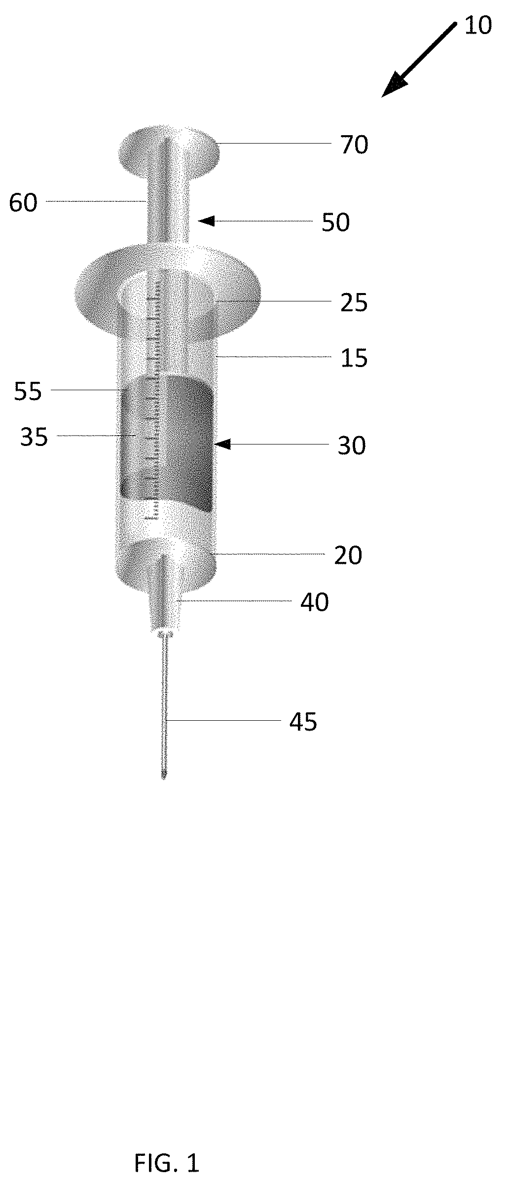
One approach to delivering cold slurry is to inject the cold slurry under a patient's skin using a syringe 10 shown in FIG. 1. The syringe 10 includes a syringe body 15 having a first end 20 and a second end 25. The syringe body 15 defines a cavity 30 for holding cold slurry 35. Extending from the first end 20, there is an outlet 40 defining a passageway that is in fluid communication with the cavity 30. The outlet serves as a port for discharging the cold slurry 35 from the cavity 30 or a cool fluid that transitions to a slurry. Extending from the outlet 40 there is hollow needle 45 for piercing through the patient's skin and providing a conduit from delivering the cold slurry 35 at or near a tissue the targeted for the cold slurry treatment.
The syringe 10 further includes a plunger 50 that slides within the cavity 30 between the first end 20 and the second end 25. At one end, facing the first end 20 of the syringe body 15, the plunger 50 includes a stopper 55 for pushing the cold slurry 35. A stem 60 extends from the stopper 55 towards the second end 25 and terminates at a flange 70. In use, to deliver the cold slurry 35 to a target tissue, a clinician pierces the patient's skin with the needle 45 and advances the needle 45 to a location at or near the target tissue. The clinician then pressed down on the syringe flange 70, which in turn delivers the cold slurry 35 from the cavity 30 through the outlet 40 and out the needle 45 to the target tissue.
The cold slurry is preferably kept at a proper treatment temperature. Depending on the tissue being treated, cold slurry temperature ranges from about 10.degree. C. to about -50.degree. C. Cold slurry melts quickly, so temperature must be maintained, especially when multiple injections are used.
A cold slurry syringe according to the invention has enhanced features for delivering a cold slurry into the human body. A syringe of the invention includes a syringe body for holding a volume of cold slurry (or a cool fluid that transitions to a cold slurry), a plunger that slides within the syringe body for ejecting the cold slurry, and a tapered syringe head for delivering an even flow of cold slurry. The taper prevents, or assists in preventing, clogging or phase change of the material in the syringe. An agitator can be added to keep the cold slurry from agglomerating and clogging the cold slurry syringe. The agitator can have many forms such as vibration, rotation, and use of augers. Insulation added around the cold slurry syringe can keep the cold slurry from melting too quickly. A ball screw drive, or other mechanism for controlling content pressure and/or flow from the device, can be added to provide a smooth and consistent application of pressure as the cold slurry is delivered. The cold slurry flow can be enhanced by adding a streamline flow feature that reduces the occurrence of eddies or swirls inside the syringe. This feature helps maintain the composition and consistency of the cold slurry.
One aspect of the invention is a device comprising a syringe body having a first end, a second end, and a longitudinal axis extending through the first and second ends. The syringe body further includes an interior lumen defined by an interior wall of the syringe body. The interior lumen is configured to receive and contain a volume of cold slurry. In some examples, the cold slurry can be made inside the syringe. In such examples, the interior lumen receives a cool fluid where it is cooled down to become a cold slurry. The device further has a plunger that is slideably movable within the interior lumen between the first and second ends along the longitudinal axis. The plunger includes a stopper and a stem extending from the stopper.
The device further has a syringe head extending from the first end of the syringe body along the longitudinal axis. The syringe head includes an inlet defining a first passageway in fluid communication with the interior lumen of the syringe body. The first passageway has a first diameter that is about the same as a diameter of the interior lumen. The syringe head further includes an outlet spaced a predetermined distance from the inlet along the longitudinal axis. The outlet defines a second passageway in fluid communication with the outside to serve as an exit for delivering cold slurry. The second passageway has a second diameter smaller than the first diameter. Extending between the inlet and outlet there is a reducer. The reducer defines a third passageway in fluid communication with the first and second passageways. The third passageway has a third diameter tapering from the first diameter to the second diameter.
BRIEF DESCRIPTION OF DRAWINGS
FIG. 1 shows a syringe for delivering cold slurry.
FIG. 2A is a cross section view of an example cold slurry syringe.
FIG. 2B is a cross section view of an example syringe head.
FIG. 2C is a cross section view of an example syringe head with projections.
FIG. 3A is a cross section view of an example cold slurry syringe with an agitator.
FIGS. 3B and 3C are views of the agitator circulating cold slurry within the cold slurry syringe.
FIG. 3D is a view of another example cold slurry syringe with an agitator.
FIGS. 4A and 4B are views of different motor configurations for rotating the agitator.
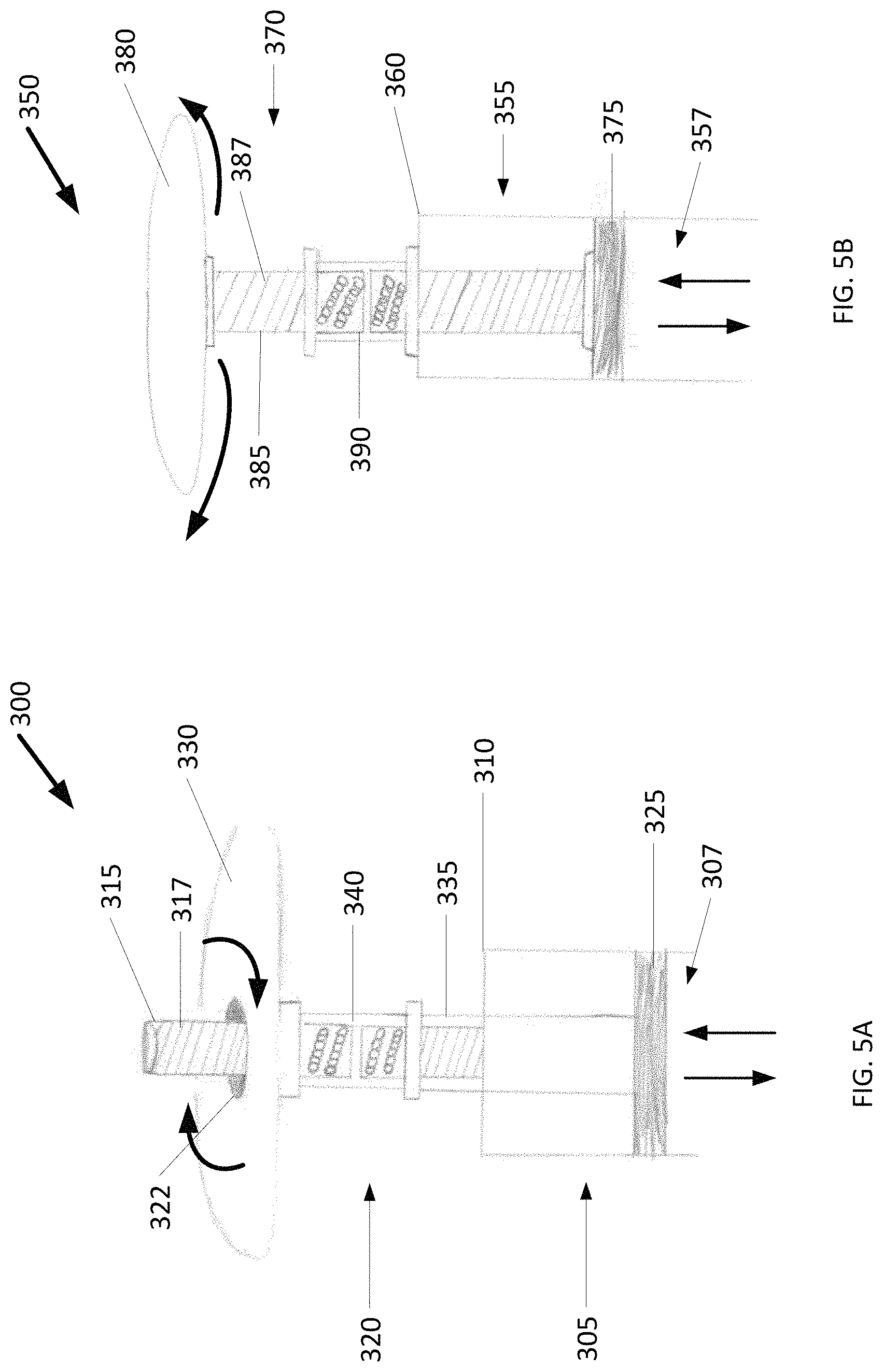
FIGS. 5A and 5B are views of example cold slurry syringes each with a ball screw drive for moving a plunger within a syringe body and delivering cold slurry.
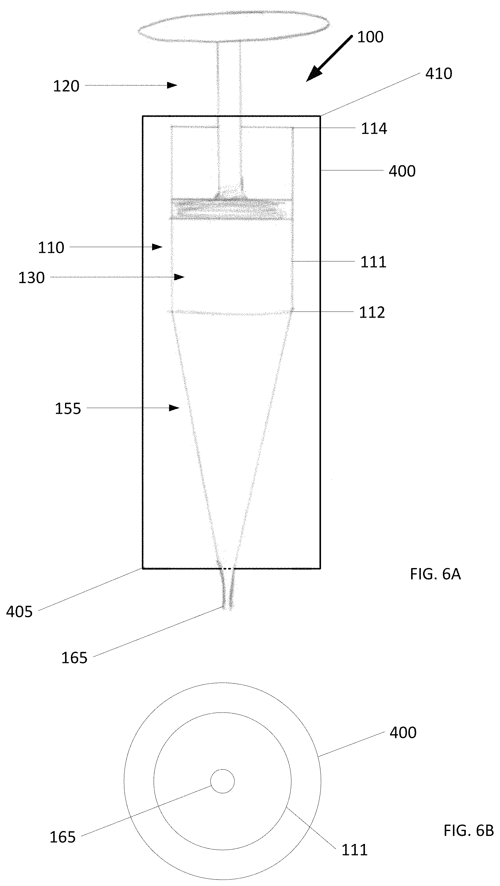
FIG. 6A is a view of a cold slurry syringe having insulation for limiting heat from transferring from the environment surrounding the cold slurry syringe to the cold slurry.
FIG. 6B is a cross section view of the cold slurry syringe with insulation of FIG. 6A.
FIG. 7A is a view of an example of a streamline flow feature.
FIG. 7B is a view of devices for generating and delivering cold slurry that incorporate the streamline flow feature.
DETAILED DESCRIPTION
The present invention provides a cold slurry syringe with enhanced features for delivering cold slurry into the human body. A cold slurry syringe of the invention includes a syringe body for holding a volume of cold slurry, a plunger that slides within the syringe body for ejecting the cold slurry, and a tapered syringe head for delivering an even flow of cold slurry. An agitator can be added to the cold slurry syringe to keep the cold slurry from agglomerating and clogging the cold slurry syringe. A ball screw drive, or other mechanism for controlling flow of pressure, can be added to the cold slurry syringe to provide a smooth and consistent application of pressure as the cold slurry is delivered. Insulation added around the cold slurry syringe can keep the cold slurry from melting too quickly. The flow of cold slurry can be enhanced by adding a streamline flow feature to the cold slurry syringe that can reduce eddies or swirls from occurring inside the cold slurry syringe. Examples of the aforementioned enhancements and others are now described in greater detail below.
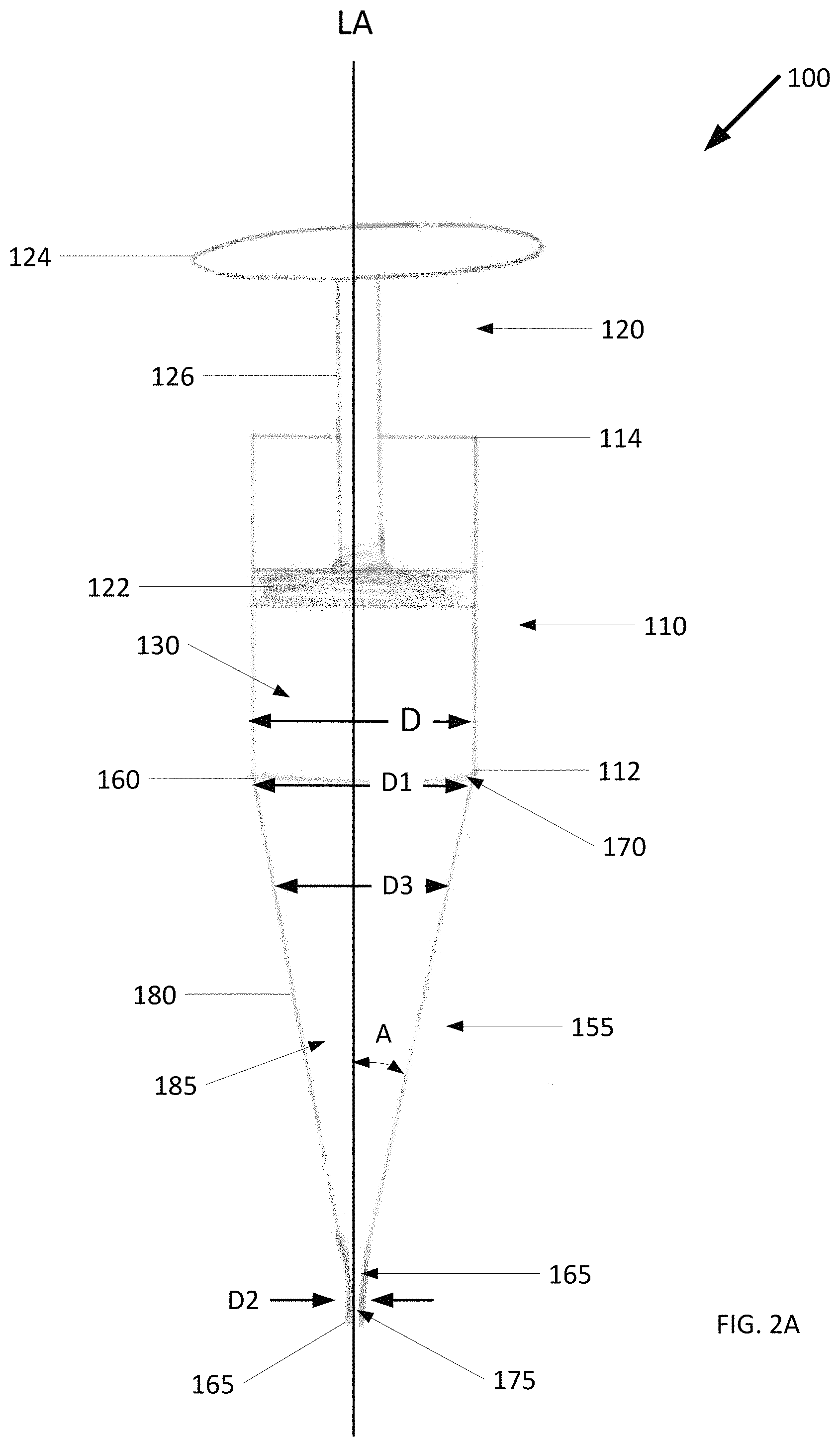
FIG. 2 shows an example cold slurry syringe 100. The cold slurry syringe 100 includes a syringe body 110 having a first end 112, a second end 114, and a longitudinal axis LA extending through the first end 112 and the second end 114. The cold slurry syringe 100 also includes an interior lumen 130 defined by the interior wall of the syringe body 110 to receive and contain cold slurry.
The cold slurry syringe 100 further includes a plunger 120 at least partially disposed within the interior lumen 130. The plunger 120 is configured to move in and out of the syringe body 110 between the first end 112 and the second end 114. The plunger 120 includes a stopper 122, a plunger head 124, and a stem 126 extending between the stopper 122 and the plunger head 124 along the longitudinal axis LA. The stopper 122 and the plunger head 124 are spaced apart at a predetermined distance.
The syringe body 110 can be made of any type of biocompatible pharmacologically inert material suitable for use in containing and supplying fluids to be provided within a human body. Exemplary materials for the syringe body 110 include plastic, such as polyethylene or polypropylene, and glass. The cold slurry syringe 100 can be any size that is suitable to hold one or more aliquots of cold slurry for delivery to the target tissue. The volume capacity of the cold slurry syringe 100 is typically between 1 ml and 60 ml, although capacity outside of those volumes is also contemplated.
The cold slurry syringe 100 further includes a syringe head 155 extending from the first end 112 of the syringe body 110 along the longitudinal axis LA. The syringe head 155 has an inlet 160 and an outlet 165 spaced a predetermined distance from the inlet 160 along the longitudinal axis LA. The inlet 160 defines a first passageway 170 in fluid communication with the interior lumen 130. The interior lumen 130 has a diameter D and the first passageway 170 has a first diameter D1 that is about the same as the interior lumen diameter D. The outlet 165 defines a second passageway 175 in fluid communication with the outside environment and serves as an exit for delivering the cold slurry. The second passageway 175 has a second diameter D2 that is smaller than the first diameter D1.
Extending between the inlet 160 and outlet 165, there is a reducer 180 defining a third passageway 185 in fluid communication with the first passageway 170 and the second passageway 175. The third passageway 185 has a third diameter that tapers from the first diameter D1 to the second diameter D2. This arrangement of passageways provides a smooth transition that allows the cold slurry to flow evenly from the interior lumen 130 through the inlet 160 and out the outlet 165. Reducing turbulence in the cold slurry flow can reduce the possibility that ice particles making up the cold slurry will aggregate and clog the cold slurry syringe 100.
The configuration and geometry of the syringe head 155 can be changed to alter the flow characteristics of the cold slurry. For example, FIG. 2B shows an example of the syringe head in which the inlet 160 and the outlet 165 have walls that are generally parallel with the longitudinal axis LA. In this example, the first diameter D1 extends over a distance d1 such that the cold slurry travels this distance through the first passageway 170 before the cold slurry flow is narrowed by the reducer 180 and increases in speed. Similarly, the second diameter D1 extends over a distance d2 such that the cold slurry travels this distance through the second passageway 175 before it exits the cold slurry syringe 100. In another example, an angle made between the longitudinal axis LA and an interior wall of the third passageway 185 (denoted in the figure as A) can be between 0 and 90 degrees. Preferably the angle is between about 10 and about 80 degrees and more preferably between about 20 and 70 degrees.
The syringe head 155 can include features for improving the flow of cold slurry. For example in FIG. 2C, the syringe head 155 includes projections 190 extending from an interior wall of the third passageway 185 toward the longitudinal axis LA. Ice particles making up the cold slurry can aggregate together and form ice clumps that can clog the cold slurry syringe 100 and impede cold slurry delivery. As the cold slurry flows through the syringe head 155, the projections 190 break up the ice clumps and, thereby, reduce the likelihood of clogging the cold slurry syringe. It is also contemplated that other areas of the cold slurry syringe can be lined with projections to improve the flow of cold slurry.
The cold slurry syringe 100 also includes at least one needle 140 (not shown) extending from the outlet 165. The needle can have a thickness between 7 gauge and 34 gauge; and can have a length between 1/4'' and 10'', such as about 1/4'', 1/2'', 1'', 2'', 3'', 4'', 5'', 6'', 7'', 8'', 9'', or 10''. Preferably, the needle is a hypodermic needle. Exemplary needle materials include, but are not limited to, stainless steel and carbon steel, with or without nickel plating.
In a convenient example, the outlet 165 is configured to receive and engage the needle. For example, the outlet 165 and the needle are Luer lock connectors that twist together to make a Luer lock connection. In another example, the outlet 165 is a slip tip onto which the needle is connected. A cold slurry syringe with a slip tip outlet can be connected to tubing or other flexible conduit. In this case, cold slurry is delivered through the tubing.
In order for cold slurry to pass through the needle without clogging, the largest cross-section of the ice particles must be smaller than the internal diameter of the needle. For example, the largest cross section can be less than about 95% of the internal diameter, less than about 85% of the internal diameter, less than about 75% of the internal diameter, less than about 65% of the internal diameter, less than about 55%, and preferably about 50% of the internal diameter. Exemplary ice particle sizes for various internal diameters, as disclosed in International Patent Application No. PCT/US2015/047292, are provided below in Table 1. It is to be understood that these particles sizes are only meant to be exemplary and not for limitation.
TABLE-US-00001 Nominal Internal Recommended Largest Cross- Needle Gauge Diameter Section of Ice Particles 7 3.81 mm 1.905 mm 8 3.429 mm 1.7145 mm 9 2.997 mm 1.4985 mm 10 2.692 mm 1.346 mm 11 2.388 mm 1.194 mm 12 2.159 mm 1.0795 mm 13 1.803 mm 0.9015 mm 14 1.6 mm 0.8 mm 15 1.372 mm 0.686 mm 16 1.194 mm 0.597 mm 17 1.067 mm 0.5335 mm 18 0.838 mm 0.419 mm 19 0.686 mm 0.343 mm 20 0.603 mm 0.3015 mm 21 0.514 mm 0.257 mm 22 0.413 mm 0.2065 mm 22s 0.152 mm 0.076 mm 23 0.337 mm 0.1685 mm 24 0.311 mm 0.1555 mm 25 0.26 mm 0.13 mm 26 0.26 mm 0.13 mm 26s 0.127 mm 0.0635 mm 27 0.21 mm 0.105 mm 28 0.184 mm 0.092 mm 29 0.184 mm 0.092 mm 30 0.159 mm 0.0795 mm 31 0.133 mm 0.0665 mm 32 0.108 mm 0.054 mm 33 0.108 mm 0.054 mm 34 0.0826 mm 0.0413 mm
Returning back to the cold slurry syringe 100, the plunger 120, including the stopper 122 and the stem 126, can be any type of biocompatible, pharmacologically inert material suitable for coming in contact with sterile substances to be provided within a human body. Exemplary materials for the plunger 120 include plastic, such as polyethylene or polypropylene, and glass. With respect to the stopper 122, a portion or all of the stopper 122 can be a rubber material, such that a seal is formed between the sides of the stopper 122 and the interior wall of the syringe body 110. The rubber material can be any rubber suitable for coming in contact with sterile substances to be provided to the human body, such as natural rubber latex or a synthetic rubber.
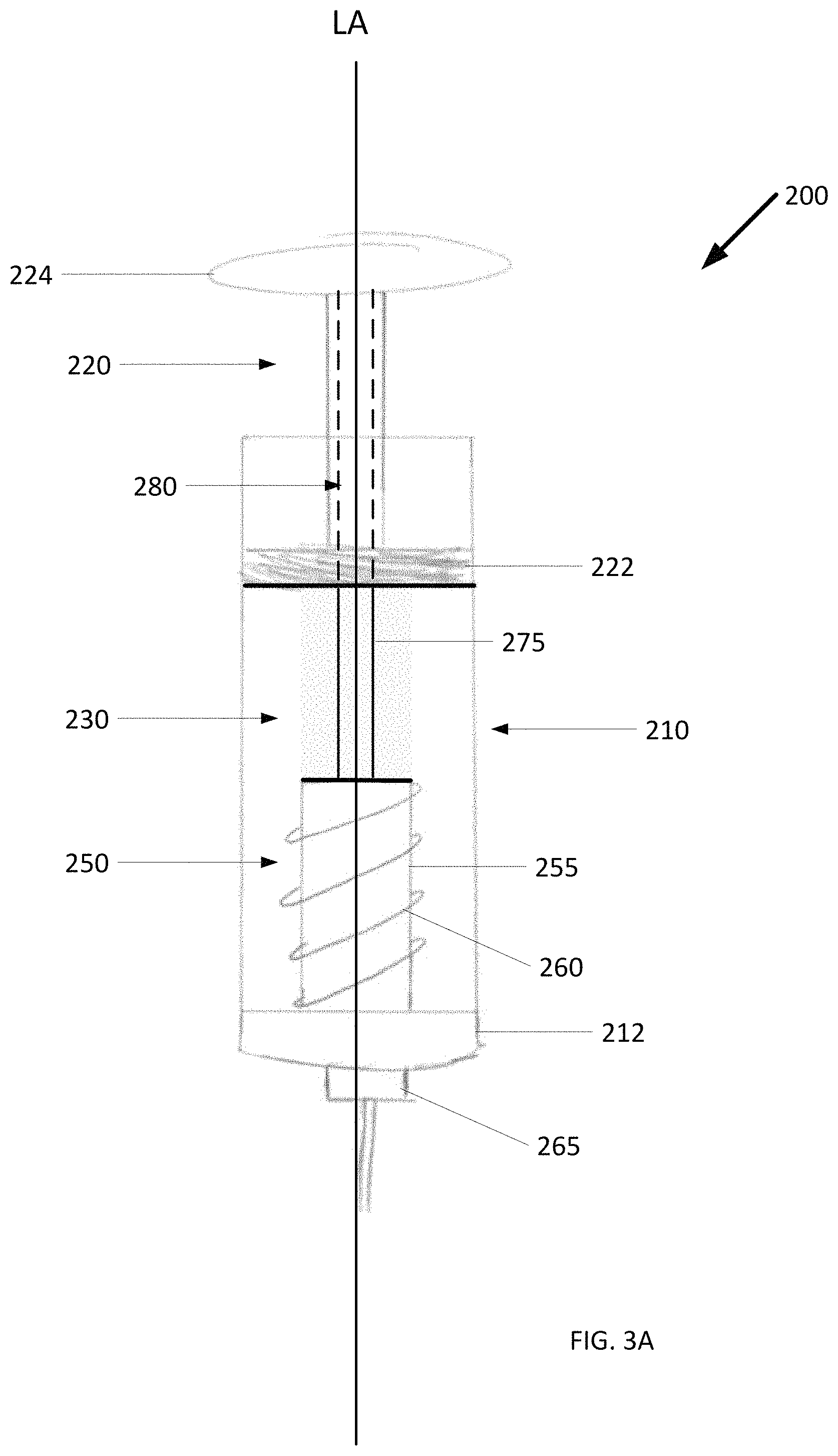
To keep ice particles making up the cold slurry from aggregating, as the cold slurry is contained within a cold slurry syringe awaiting delivery, the cold slurry can be agitated. FIG. 3A shows an example cold slurry syringe 200 with an agitator 250 for stirring the cold slurry syringe and retarding the formation of ice clumps, which can clog the cold slurry syringe 200. The agitator 250 is housed within an interior lumen 230 between a plunger 220 and a first end 212 of a syringe body 210. The agitator 250 includes a hub 255 and a plurality of fins 260 radiating from the hub 255 towards the wall of the interior lumen 230.
As shown, the fins 260 extend out from the hub 255 along a plane that intersects longitudinal axis LA at an angle forming a spiral (or helical) pattern. Alternatively, the fins can extend out from the hub along a plane wherein one dimension of the plane is defined by the longitudinal axis. The agitator 250 can be made out of any material that is suitable for contact with sterile compositions to be delivered to the human body, including those exemplary materials previously provided with respect to the syringe body 110, plunger 120, and needle of FIGS. 2A-2C.
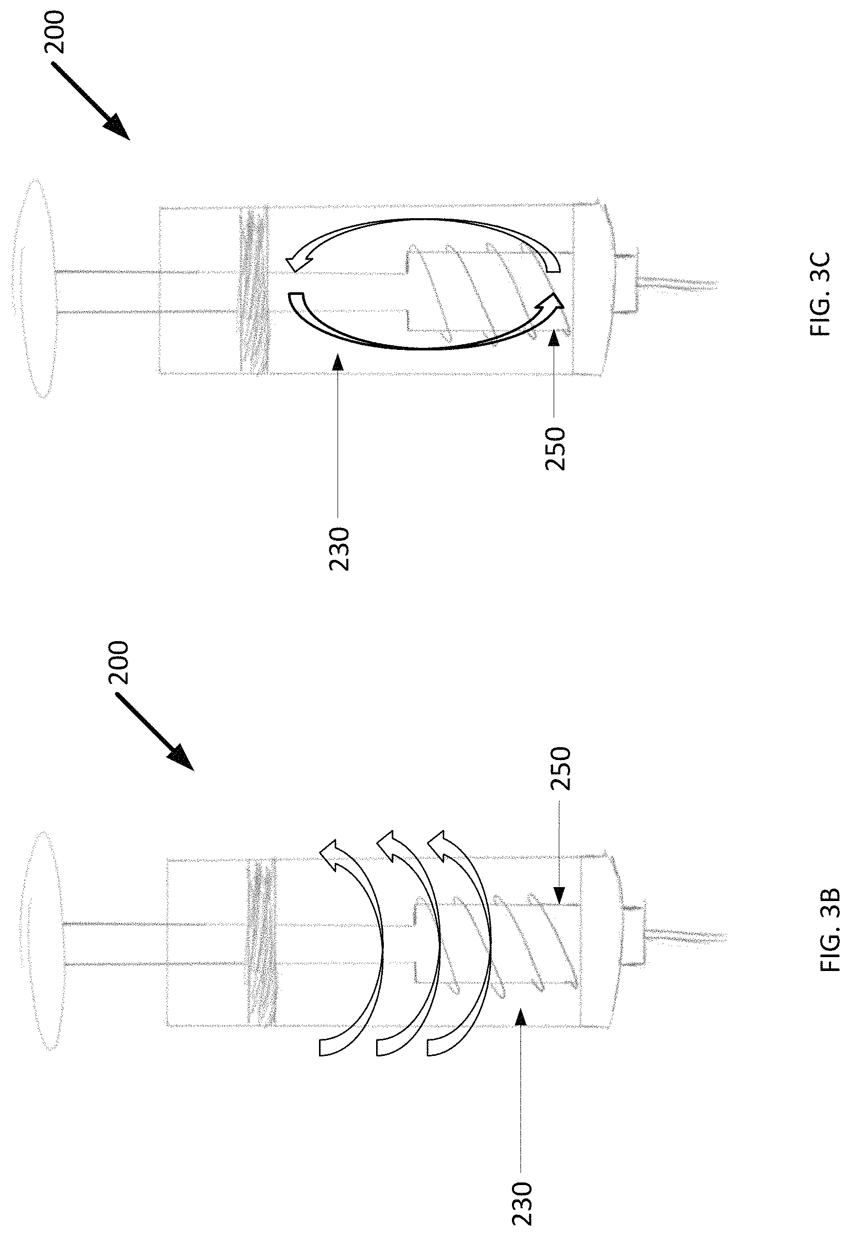
The agitator 250 includes a shaft 275 extending from the hub 255 and through a central bore 280 of the plunger 220. Rotating the shaft 275 turns the agitator 250, which in turn causes cold slurry to flow within the interior lumen 230 in multiple directions, as shown in FIGS. 3B and 3C. As shown, the shaft 275 terminates at a plunger head 224. In this example, the agitator 250 is turned manually by turning the plunger head 224 by hand or with a crank.
In another example, rotation of the agitator 250 is aided by the use of a motor 285. The motor 285 can be drivingly coupled to the cold slurry syringe 200 in any number of ways. For example, the motor 285 is directly coupled to the shaft 275, as shown in FIG. 4A, with the shaft 275 acting as a gear. In another example shown in FIG. 4B, the motor 285 is coupled to the plunger head 224 and the shaft 275 is fixed to the plunger head 224. In this case, the plunger head 224 acts a gear, which when driven by the motor (not shown), spins the agitator 250.
The agitator 250 can have a number of different configurations. For example, FIG. 3D shows an agitator 282 with a hub 284 shaped like a frustum of a cone. A base 286 of the hub 284 (i.e., wider end) faces the first end 212 of the syringe body 210. The hub 284 and fins 288 define a mixing profile. As shown, the mixing profile of the agitator 282 increases in the direction toward an outlet 265. Advantageously, this arrangement facilitates breaking up of ice clumps and improves the flow of cold slurry.
Referring back to FIG. 2A, to deliver cold slurry using the cold slurry syringe 100, for example, a clinician presses down on the plunger head 124, which in turn forces the plunger 120 downward towards the first end 112 of the syringe body 110. The force of the descending plunger 120 on the cold slurry, in conjunction with the increase in pressure of the cold slurry, forces the cold slurry out the syringe body and delivers the cold slurry. In this example, a linear motion is used to deliver the cold slurry. Other examples of the invention, convert a rotary motion to a linear motion for driving the plunger and delivering the cold slurry.
FIG. 5A shows the user end of an example syringe 300 in which a rotary motion is converted into a linear motion for delivering cold slurry. The syringe 300 includes a syringe body 305 having a first end (not shown) and an opposing second end 310. Extending away from the syringe body 305 from the second end 310 is a fixed screw 315 with threads 318.
The syringe 300 further includes a plunger 320 partially disposed within an interior lumen 307 containing a volume of cold slurry. The plunger 320 has a through bore 322 for receiving the screw 315 allowing the plunger 320 to rotate about the screw 315. The plunger 320 further includes a stopper 325 at one end and a plunger head 330 at an opposing end. A stem 335 extends between the stopper 325 and the plunger head 330 separating the two by a distance. The stem 335 further includes a nut 340 for engaging the screw threads 317. Rotating the plunger head 330 in a first direction moves the stopper 325 from the second end 310 to the first end. This in turn, pushes the cold slurry out of the interior lumen 307 and delivers the cold slurry to a target tissue. Rotating the plunger head 330 in a second direction moves the stopper 325 from the first end to the second end 310. This motion can be used to draw cold slurry into the interior lumen 307 from, for example, a cold slurry generator (an example of which is described in U.S. Provisional Application 62/416,484, which is incorporated herein in its entirety).
FIG. 5B shows the user end of another example cold slurry syringe 350 in which a rotary motion is converted into a linear motion for delivering cold slurry. The cold slurry syringe 350 includes a syringe body 355 having a first end (not shown) and an opposing second end 360. A nut 390 is fixed to the second end 360 of the syringe body 355.
The cold slurry syringe 350 further includes a plunger 370 partially disposed within an interior lumen 357 containing a volume of cold slurry. The plunger 370 includes a stopper 375 at one end and a plunger head 380 at an opposing end. A screw 385 extends between the stopper 375 and the plunger head 380 separating the two by a distance. The screw 385 further includes threads 387 for engaging the nut 390, which is fixed to the second end 360 of the syringe body 355. Rotating the plunger head 380 in a first direction moves the stopper 375 from the second end 360 to the first end. This in turn, pushes the cold slurry out of the interior lumen 357 and delivers the cold slurry to a target tissue. Rotating the plunger head 380 in a second direction moves the stopper 375 from the first end to the second end 360. This motion can be used to draw cold slurry into the interior lumen 357 from, for example, a cold slurry generator (an example of which is described in U.S. Provisional Application 62/416,484, which is incorporated herein in its entirety). Some examples of the cold slurry syringe 350 have a motor drivingly coupled to the plunger head 380, for example, by way of gears, belt and pulley or rack and pinion. The motor drives the head in the first direction to inject the cold slurry and drives the head on the second direction to withdraw the cold slurry. The motor, in turn, can be operable coupled to an electronic controller. Advantageously, with such a controller cold slurry can be injected or withdraw in an automated, autonomous or regulated fashion. The motor can be electrical DC or AC motor. Example motors include rotational and vibrational motors.
As shown in FIGS. 5A and 5B, the screw 315/385 can be a ball screw and the nut 340/390 can a ball nut that make up a ball screw drive. The ball nut is packaged as an assembly with recirculating ball bearings that roll in matching forms in the interface between the ball screw and the ball nut. With rolling elements, the ball screw drive has a very low coefficient of friction (on the order of u=0.01 to u=0.005), and is suitable for use with high precision and can apply/withstand high thrust loads. (In comparison, a conventional slide screw having similar a lead angle has a coefficient of friction on the order of u=0.1 and requires three times the driving torque.) A benefit to using the ball screw drive in the cold slurry syringe 300/350 is that it allows for a smooth and consistent application of pressure as cold slurry is ejected. The ability to withstand high thrust loads allows for the cold slurry to maintain a smooth, consistent force directed downwards and out of the cold slurry syringe 300/350, counteracting any opposing force to the system.
Another example of the cold slurry syringe includes a hydraulic piston for controlling the rate at which the cold slurry syringe is pressed and the cold slurry is ejected. The hydraulic piston is coupled to the plunger in order to maintain a constant and consistent pressure on the plunger throughout the closed system while plunging and delivering the cold slurry. In this mechanism, the hydraulic piston is mounted on top of the plunger, which with mechanical force, acts on a small cross-sectional area, displacing an incompressible fluid and displacing an equal volume of slurry at a constant rate from the syringe body. This process is performed in order to control possible changes in phase, temperature, and/or pressure on the slurry.
In general, to limit heat from transferring from the environment surrounding the cold slurry syringe to the cold slurry and melting the cold slurry, the cold slurry syringe can be surrounded in insulation. In one embodiment according to the present invention shown in FIG. 6A, an insulation 400 surrounds the syringe body 110 and maintains a temperature of the cold slurry within the interior lumen 130. As best seen in the cross section of FIG. 6B (with the plunger 120 omitted for clarity), the insulation 400 is concentric with an outer surface 111 of the syringe body 110.
As shown in FIG. 6A, the insulation 400 extends past the first end 112 of the syringe body 110 towards the outlet 165 at its bottom 405. The insulation 400 extends past the second end 114 of the syringe body 110 towards the plunger head 124 at its top 410. As such, the insulation 400 substantially encompasses the cold slurry syringe 100. Alternatively, the insulation 400 can surround the syringe body 110 with the bottom 405 ending at or near the first end 112 and the top 410 ending at or near the second end 114.
In a convenient example, the insulation 400 is an insulation sleeve for receiving the cold slurry syringe 100. The insulation sleeve can have an open end through which the cold slurry syringe 100 is loaded. A removable cap can further be provided at the open end to allow for insertion and subsequent enclosure of the cold slurry syringe 100 within the insulation sleeve. In another example, the insulation sleeve is of a clamshell design with two halves.
The insulation 400 can be made out of fiberglass insulation, foam insulation, gel insulation, and aerogel insulation, just to name a few examples. The insulation 400 can also be rigid insulation so that when pressure is exerted on the cold slurry syringe (e.g., when delivering cold slurry), the syringe body does not expand or change shape. Similar to the components of the cold slurry syringe, the insulation 400 can also be made out of any material that is biocompatible and pharmacologically inert.
A streamline flow feature can be used to maintain velocity, pressure, and other properties of cold slurry flow from when the cold slurry is generated to when the cold slurry is injected. FIG. 7A shows an example of the streamline flow feature 500 having a core structure 505 that extends between a first end 510 and a second end 515. The core structure 505 defines a passageway 520 through which cold slurry flows.
The passageway 520 extends along a longitudinal axis LA between the first end 510 and the second end 515 with a plane of the passageway 520 intersecting the longitudinal axis LA at an angle forming a spiral (or helical) pattern. Because of this arrangement, cold slurry can flow throw through the streamline flow feature 500 without turbulence, in parallel layers with no disruption between the layers, and with no cross-currents perpendicular to the flow direction. The streamline flow feature 500 can also reduce the occurrence of eddies or swirls.
Cold slurry moves through the streamline flow feature 500 as a laminar flow allowing ice particles to move parallel to the passageway surface. This can help maintain cold slurry composition (e.g. ice content) from when the cold slurry is generated to when the cold slurry is injected in a patient. It can further help reduce agglomeration and/or inconsistency in cold slurry composition. FIG. 7B shows the streamline flow feature used in devices for generating and delivering cold slurry, including a cold slurry generator 525 (of which only an internal component is shown), a cold slurry syringe 530, tubing 535 for transferring cold slurry from the cold slurry generator 525 to the cold slurry syringe 530, and a needle 540 for piercing the patient's skin and delivering cold slurry to a target tissue.
The cold slurry syringes 100, 200, 300, 350, and 530 described above can be used to deliver a wide variety of cold slurries. For example, the cold slurry can have a temperature of about 10.degree. C., 7.degree. C., 5.degree. C., 4.degree. C., 3.degree. C., 2.degree. C., 1.degree. C., 0.degree. C., -1.degree. C., -2.degree. C., -3.degree. C., -4.degree. C., -5.degree. C., -10.degree. C., -15.degree. C., -20.degree. C., -30.degree. C., -40.degree. C., and -50.degree. C. The cold slurry can contain between about 0.1% and about 75% ice by weight, between about 0.1% and 1% ice by weight, between about 1% and 10% ice by weight, between about 10% and about 20% ice by weight, between about 20% and about 30% ice by weight, between about 30% and about 40% ice by weight, between about 40% and about 50% ice by weight, between about 50% and about 60% ice by weight, between about 60% and about 70% ice by weight, and greater than about 50% ice by weight. (The proportions of ice by volume are slightly higher due to the densities of solid and liquid water.) The cold slurry can include ice particles having a largest cross-sectional dimension that is less than about 2 mm, about 1.75 mm, about 1.5 mm, about 1.25 mm, about 1 mm, about 0.9 mm, about 0.8 mm, about 0.7 mm, about 0.6 mm, about 0.5 mm, about 0.4 mm, about 0.3 mm, about 0.2 mm, or about 0.1 mm. Other exemplary cold slurry compositions, slurry temperatures, and cross-sectional dimensions of ice particles are provided in PCT/US2015/047292, which is incorporated herein in its entirety. It is to be understood that an advantage of the cold slurry in accordance with the present invention is that the composition of the cold slurry is suitable to delivery to tissues within the body, such that the slurry can be delivered to a tissue within the body of a patient and remain within the body (e.g. no removal of the slurry is necessary after cooling has been effected).
EQUIVALENTS
While the present invention has been described in conjunction with certain preferred embodiments, one of ordinary skill, after reading the foregoing specification, will be able to effect various changes, substitutions of equivalents, and other alterations to the apparatuses and methods set forth herein.
* * * * *
D00000
D00001
D00002
D00003
D00004
D00005
D00006
D00007
D00008
D00009
D00010
XML
uspto.report is an independent third-party trademark research tool that is not affiliated, endorsed, or sponsored by the United States Patent and Trademark Office (USPTO) or any other governmental organization. The information provided by uspto.report is based on publicly available data at the time of writing and is intended for informational purposes only.
While we strive to provide accurate and up-to-date information, we do not guarantee the accuracy, completeness, reliability, or suitability of the information displayed on this site. The use of this site is at your own risk. Any reliance you place on such information is therefore strictly at your own risk.
All official trademark data, including owner information, should be verified by visiting the official USPTO website at www.uspto.gov. This site is not intended to replace professional legal advice and should not be used as a substitute for consulting with a legal professional who is knowledgeable about trademark law.