Lithium ion battery non-aqueous electrolyte and lithium ion battery
Shi , et al. De
U.S. patent number 10,497,975 [Application Number 15/558,551] was granted by the patent office on 2019-12-03 for lithium ion battery non-aqueous electrolyte and lithium ion battery. This patent grant is currently assigned to SHENZHEN CAPCHEM TECHNOLOGY CO., LTD.. The grantee listed for this patent is SHENZHEN CAPCHEM TECHNOLOGY CO., LTD. Invention is credited to Qun Chen, Shiguang Hu, Qi Huang, Qiao Shi, Xue Zhou.


View All Diagrams
| United States Patent | 10,497,975 |
| Shi , et al. | December 3, 2019 |
Lithium ion battery non-aqueous electrolyte and lithium ion battery
Abstract
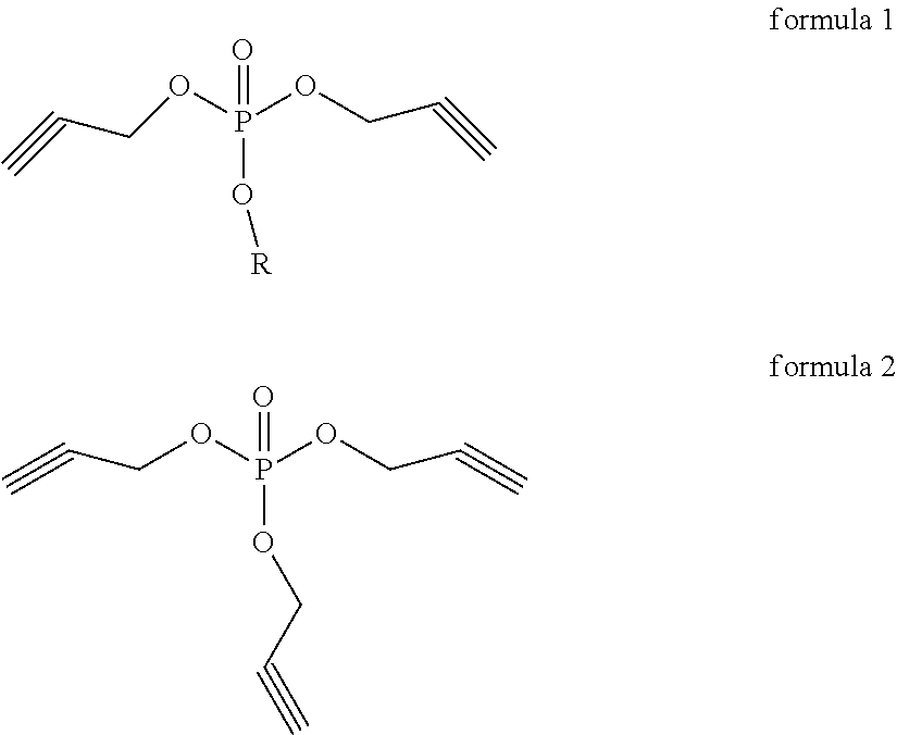
Disclosed is a lithium ion battery non-aqueous electrolyte and a lithium ion battery, in which the electrolyte comprises: a non-aqueous organic solvent, a lithium salt and an additive, said additive comprises: a compound represented by the structural formula 1 and a compound represented by the structural formula 2, in which R is an alkyl selected from an alkyl group having 1 to 4 carbon atoms, the ratio of the content of the compound represented by the structural formula 1 to the total mass of the lithium ion battery non-aqueous electrolyte is 0.1% to 2%, and the ratio of the content of the compound represented by the structural formula 2 to the total mass of the lithium ion battery non-aqueous electrolyte is less than 0.5%. ##STR00001##
| Inventors: | Shi; Qiao (Shenzhen, CN), Hu; Shiguang (Shenzhen, CN), Chen; Qun (Shenzhen, CN), Huang; Qi (Shenzhen, CN), Zhou; Xue (Shenzhen, CN) | ||||||||||
|---|---|---|---|---|---|---|---|---|---|---|---|
| Applicant: |
|
||||||||||
| Assignee: | SHENZHEN CAPCHEM TECHNOLOGY CO.,
LTD. (Shenzhen, Guangdong, CN) |
||||||||||
| Family ID: | 55506751 | ||||||||||
| Appl. No.: | 15/558,551 | ||||||||||
| Filed: | November 24, 2015 | ||||||||||
| PCT Filed: | November 24, 2015 | ||||||||||
| PCT No.: | PCT/CN2015/095386 | ||||||||||
| 371(c)(1),(2),(4) Date: | September 14, 2017 | ||||||||||
| PCT Pub. No.: | WO2017/075851 | ||||||||||
| PCT Pub. Date: | May 11, 2017 |
Prior Publication Data
| Document Identifier | Publication Date | |
|---|---|---|
| US 20180062203 A1 | Mar 1, 2018 | |
Foreign Application Priority Data
| Nov 4, 2015 [CN] | 2015 1 0742728 | |||
| Current U.S. Class: | 1/1 |
| Current CPC Class: | H01M 10/0525 (20130101); H01M 10/0568 (20130101); H01M 10/0567 (20130101); H01M 10/0569 (20130101); H01M 4/131 (20130101); H01M 2220/20 (20130101); H01M 2300/004 (20130101); H01M 4/133 (20130101) |
| Current International Class: | H01M 4/131 (20100101); H01M 10/0569 (20100101); H01M 10/0567 (20100101); H01M 10/0525 (20100101); H01M 4/13 (20100101); H01M 10/0568 (20100101); H01M 4/133 (20100101) |
References Cited [Referenced By]
U.S. Patent Documents
| 6511772 | January 2003 | Gan |
| 6919141 | July 2005 | Gan et al. |
| 2002/0094479 | July 2002 | Gan |
| 2003/0113635 | June 2003 | Gan |
| 2009/0176164 | July 2009 | Matsui et al. |
| 2009/0181301 | July 2009 | Kim et al. |
| 2010/0255369 | October 2010 | Hwang et al. |
| 2012/0018077 | January 2012 | Lee et al. |
| 2012/0034533 | February 2012 | Hong et al. |
| 2012/0100436 | April 2012 | Inou et al. |
| 2012/0107700 | May 2012 | Deguchi |
| 2013/0122378 | May 2013 | Oh et al. |
| 2013/0183579 | July 2013 | Kim et al. |
| 2013/0323605 | December 2013 | Yamamoto et al. |
| 1558464 | Dec 2004 | CN | |||
| 1866605 | Nov 2006 | CN | |||
| 101385183 | Mar 2009 | CN | |||
| 101440105 | May 2009 | CN | |||
| 101517678 | Aug 2009 | CN | |||
| 100585935 | Jan 2010 | CN | |||
| 101882696 | Nov 2010 | CN | |||
| 102150315 | Aug 2011 | CN | |||
| 102450315 | Aug 2011 | CN | |||
| 102280664 | Dec 2011 | CN | |||
| 102332607 | Jan 2012 | CN | |||
| 102394311 | Mar 2012 | CN | |||
| 102460817 | May 2012 | CN | |||
| 102473962 | May 2012 | CN | |||
| 102983353 | Mar 2013 | CN | |||
| 103107360 | May 2013 | CN | |||
| 103151559 | Jun 2013 | CN | |||
| 103151559 | Jun 2013 | CN | |||
| 103208623 | Jul 2013 | CN | |||
| 103339783 | Oct 2013 | CN | |||
| 103441304 | Dec 2013 | CN | |||
| 103531864 | Jan 2014 | CN | |||
| 103594729 | Feb 2014 | CN | |||
| 102439776 | Apr 2014 | CN | |||
| 103715454 | Apr 2014 | CN | |||
| 103811815 | May 2014 | CN | |||
| 104300174 | Jan 2015 | CN | |||
| 104466248 | Mar 2015 | CN | |||
| 104600361 | May 2015 | CN | |||
| 104752764 | Jul 2015 | CN | |||
| 1213782 | Jun 2002 | EP | |||
| 2000-348764 | Dec 2000 | JP | |||
| 2004-165151 | Jun 2004 | JP | |||
| 2011-124039 | Jun 2011 | JP | |||
| 2012-084384 | Apr 2012 | JP | |||
| 2015060819 | Mar 2015 | JP | |||
| 20070103919 | Oct 2007 | KR | |||
| 10-1195931 | Oct 2012 | KR | |||
Other References
|
US. Appl. No. 15/557,780, Shi et al., filed Sep. 12, 2017. cited by applicant . U.S. Appl. No. 15/557,788, Shi et al., filed Sep. 12, 2017. cited by applicant . U.S. Appl. No. 15/559,014, Shi et al., filed Sep. 15, 2017. cited by applicant . International Search Report for PCT/CN2015/091506 dated May 3, 2016, and its English translation provided by WIPO. cited by applicant . Written Opinion of the International Search Authority for PCT/CN2015/091506 dated May 3, 2016, and its English translation provided by Bing.Com Microsoft Translate. cited by applicant . From CN201510481841.3, 1.sup.st Office Action dated Jul. 6, 2016 with an English translation from Espacenet Global Dossier. cited by applicant . From CN201510481841.3, Search Report dated Jun. 28, 2016. cited by applicant . From CN201510964662.5, 1st Office Action dated May 24, 2017 with an English translation from Espacenet Global Dossier. cited by applicant . From CN201510964662.5, Search Report dated May 12, 2017. cited by applicant . From CN201310624603.4, First Office Action dated Mar. 31, 2015 with an English translation from Espacenet Global Dossier. cited by applicant . From CN201310624603.4, Search Report dated Mar. 23, 2015. cited by applicant . From CN201410534841.0, First Office Action dated Feb. 25, 2016 with an English translation from Espacenet Global Dossier. cited by applicant . From CN201410534841.0, Second Office Action dated Sep. 2, 2016 with an English translation from Espacenet Global Dossier. cited by applicant . From CN20141534841.0, Third Office Action dated Mar. 1, 2017 with an English translation from Espacenet Global Dossier. cited by applicant . From CN20141534841.0, Search Report dated Feb. 17, 2016. cited by applicant . International Search Report for PCT/CN2015/098657 dated Mar. 24, 2016, and its English translation provided by WIPO. cited by applicant . Written Opinion of the International Search Authority for PCT/CN2015/098657 dated Mar. 24, 2016, and its English translation provided by Bing.Com Microsoft Translate. cited by applicant . International Search Report for PCT/CN2015/095386 dated Apr. 13, 2016, and its English translation provided by WIPO. cited by applicant . Written Opinion of the International Search Authority for PCT/CN2015/095386 dated Apr. 13, 2016, and its English translation provided by Bing.Com Microsoft Translate. cited by applicant . From CN201510742728.6, 1.sup.st office action dated Jun. 2, 2017, with an English translation from Espacenet global dossier. cited by applicant . From CN201510742728.6, Search Report dated May 19, 2017. cited by applicant . From CN2013146105.6, First Office Action dated Aug. 25, 2014, with an English translation from Espacenet global dossier. cited by applicant . From CN2013146105.6, Second Office Action dated Feb. 10, 2015, with an English translation from Espacenet global dossier. cited by applicant . From CN2013146105.6, Third Office Action dated Apr. 24, 2015, with an English translation from Espacenet global dossier. cited by applicant . From CN2013146105.6, Supplementary search dated Feb. 2, 2015. cited by applicant . International Search Report for PCT/CN2015/083624 dated Sep. 11, 2015, and its English translation provided by WIPO. cited by applicant . Written Opinion of the International Search Authority for PCT/CN2015/083624 dated Sep. 11, 2015, and its English translation provided by Bing.Com Microsoft Translate. cited by applicant . "Electronegativity-induced enhancement of thermal stability by succinonitrile as an additive for Li ion batteries", Energy & Environmental Science, 2011, 4, 4038-4045. cited by applicant . "Surface Complex Formation between Aliphatic Nitrile Molecules and Transition Metal Atoms for Thermally Stable Lithium-Ion Batteries", Applied Materials & Interfaces, 2014, 6, 8913-8920. cited by applicant. |
Primary Examiner: Douyette; Kenneth J
Attorney, Agent or Firm: Ladas & Parry, LLP
Claims
What is claimed is:
1. A lithium ion battery non-aqueous electrolyte, comprising a non-aqueous organic solvent, a lithium salt and an additive, wherein the additive comprises a compound represented by the structural formula 1 and a compound represented by the structural formula 2, in which R is an alkyl selected from an alkyl group having 1 to 4 carbon atoms, ##STR00012## a ratio of the content of the compound represented by the structural formula 1 to a total mass of the lithium ion battery non-aqueous electrolyte is 0.1% to 2%, and a ratio of the content of the compound represented by the structural formula 2 to a total mass of the lithium ion battery non-aqueous electrolyte is less than 0.5%.
2. The lithium ion battery non-aqueous electrolyte according to claim 1, wherein R is selected from the group consisting of a methyl group, an ethyl group, a propyl group, an isopropyl group, a butyl group, an isobutyl group, a sec-butyl group and a tert-butyl group.
3. The lithium ion battery non-aqueous electrolyte according to claim 1, wherein the non-aqueous organic solvent is a mixture of a cyclic carbonate of one or more than two selected from ethylene carbonate, propylene carbonate and butylene carbonate and an acyclic carbonate of one or more than two selected from dimethyl carbonate, diethyl carbonate, ethyl methyl carbonate and methyl propyl carbonate.
4. The lithium ion battery non-aqueous electrolyte according to claim 1, wherein the lithium salt is one or more than two selected from LiPF.sub.6, LiBF.sub.4, LiSbF.sub.6, LiAsF.sub.6, LiN(SO.sub.2CF.sub.3).sub.2, LiN(SO.sub.2C.sub.2F.sub.5).sub.2, LiC(SO.sub.2CF.sub.3).sub.3 and LiN(SO.sub.2F).sub.2.
5. The lithium ion battery non-aqueous electrolyte according to claim 1, wherein the additive further comprises one or more than two of vinylene carbonate, fluoroethylene carbonate and vinyl ethylene carbonate.
6. A lithium ion battery, comprising a positive electrode, a negative electrode and a diaphragm between the positive electrode and the negative electrode, and further comprising the lithium ion battery non-aqueous electrolyte according to claim 1.
7. The lithium ion battery according to claim 6, wherein the positive electrode is one or more than two selected from LiCoO.sub.2, LiNiO.sub.2, LiMn.sub.2O.sub.4, LiCo.sub.1-yM.sub.yO.sub.2, LiNi.sub.1-yM.sub.yO.sub.2, LiMn.sub.2-yM.sub.yO.sub.4 and LiNi.sub.xCo.sub.yMn.sub.zM.sub.1-x-y-zO.sub.2, M is one or more than two selected from Fe, Co, Ni, Mn, Mg, Cu, Zn, Al, Sn, B, Ga, Cr, Sr, V and Ti, and 0.ltoreq.y.ltoreq.1, 0.ltoreq.x.ltoreq.1, 0.ltoreq.z.ltoreq.1, x+y+z.ltoreq.1.
8. The lithium ion battery according to claim 6, wherein a charge cut-off voltage of the lithium ion battery is more than or equal to 4.35 V.
9. The lithium ion battery according to claim 7, wherein a charge cut-off voltage of the lithium ion battery is more than or equal to 4.35 V.
Description
CROSS REFERENCE TO RELATED APPLICATIONS
The present application is the U.S. national Phase of PCT Application No. PCT/CN2015/095386 filed on Nov. 24, 2015, which claims priority to Chinese Patent Application No. 201510472728.6 filed on Nov. 4, 2015, the disclosures of which are incorporated herein by reference in their entireties.
TECHNICAL FIELD
The present invention relates to the field of lithium ion battery electrolyte technology, and in particular to a lithium ion battery non-aqueous electrolyte and a lithium ion battery.
BACKGROUND OF THE INVENTION
At present, a non-aqueous electrolyte lithium ion battery has been increasingly more widely used in a 3 C consumer electronic product market, and with the development of new energy vehicles, the non-aqueous electrolyte lithium ion battery has been increasingly more popularized as a power source system of vehicles. These non-aqueous electrolyte batteries have been practical, but are still dissatisfactory in the aspect of durability, and especially have short service lives at a high temperature of 45.degree. C. Especially for powered vehicles and energy storage systems, the non-aqueous electrolyte lithium ion battery is requested to work properly in a cold region, so that even more considerations shall be given to high- and low-temperature performances.
In the non-aqueous electrolyte lithium ion battery, the non-aqueous electrolyte is a key factor affecting the high- and low-temperature performances of the battery. In particular, the additive in the non-aqueous electrolyte is especially important for giving play to the high- and low-temperature performances of the battery. At present, the practical non-aqueous electrolyte uses a traditional film forming additive, e.g. vinylene carbonate (VC), to ensure the excellent cycle performance of the battery. But due to poor high voltage stability, VC can hardly meet the requirements for cycle performance at 45.degree. C. under the conditions of high voltage and high temperature.
The patent document U.S. Pat. No. 6,919,141B2 discloses a phosphate additive for non-aqueous electrolyte containing an unsaturated bond, which can reduce the irreversible capacity of lithium ion batteries and improve the cycle performance of lithium batteries. Similarly, the patent document 201410534841.0 also discloses a novel phosphate compound film forming additive containing a triple bond, which can not only improve the high temperature cycle performance, but also significantly improve the storage performance. But persons skilled in the art found in their researches that a passive film formed by the phosphate additive containing the triple bond on an electrode interface has poor conductivity, resulting in a high interface impedance, significantly degrading the low-temperature performance, and inhibiting the application of the non-aqueous lithium ion battery under low-temperature conditions.
SUMMARY OF THE INVENTION
The present invention provides a lithium ion battery non-aqueous electrolyte capable of giving consideration to high- and low-temperature performances of the battery, and further provides a lithium ion battery containing the lithium ion battery non-aqueous electrolyte.
According to a first aspect of the present invention, the present invention provides a lithium ion battery non-aqueous electrolyte, including a non-aqueous organic solvent, a lithium salt and an additive, wherein the additive comprises: a compound represented by the structural formula 1 and a compound represented by the structural formula 2, in which R is an alkyl selected from an alkyl group having 1 to 4 carbon atoms,
##STR00002##
the ratio of the content of the compound represented by the structural formula 1 to the total mass of the lithium ion battery non-aqueous electrolyte is 0.1% to 2%, and the ratio of the content of the compound represented by the structural formula 2 to the total mass of the lithium ion battery non-aqueous electrolyte is less than 0.5%.
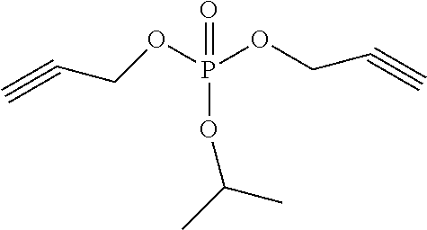
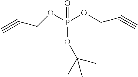
As a preferable solution of the present invention, R in the compound represented by the structural formula 1 is selected from the group consisting of a methyl group, an ethyl group, a propyl group, an isopropyl group, a butyl group, an isobutyl group, a sec-butyl group and a tert-butyl group.
As a further improved solution of the present invention, the non-aqueous organic solvent is a mixture of a cyclic carbonate of one or more than two selected from ethylene carbonate, propylene carbonate and butylene carbonate and an acyclic carbonate of one or more than two selected from dimethyl carbonate, diethyl carbonate, ethyl methyl carbonate and methyl propyl carbonate.
As a further improved solution of the present invention, the lithium salt is one or more than two selected from LiPF.sub.6, LiBF.sub.4, LiSbF.sub.6, LiAsF.sub.6, LiN(SO.sub.2CF.sub.3).sub.2, LiN(SO.sub.2C.sub.2F.sub.5).sub.2, LiC(SO.sub.2CF.sub.3).sub.3 and LiN(SO.sub.2F).sub.2.
As a further improved solution of the present invention, the additive further comprises one or more than two of vinylene carbonate, fluoroethylene carbonate and vinyl ethylene carbonate.
As a second aspect of the present invention, the present invention provides a lithium ion battery, comprising a positive electrode, a negative electrode and a diaphragm between the positive electrode and the negative electrode, and further comprising the lithium ion battery non-aqueous electrolyte according to the first aspect.
As a further improved solution of the present invention, the positive electrode is one or more than two selected from LiCoO.sub.2, LiNiO.sub.2, LiMn.sub.2O.sub.4, LiCo.sub.1-yM.sub.yO.sub.2, LiNi.sub.1-yM.sub.yO.sub.2, LiMn.sub.2-yM.sub.yO.sub.4 and LiNi.sub.xCo.sub.yMn.sub.zM.sub.1-x-y-zO.sub.2, M is one or more than two selected from Fe, Co, Ni, Mn, Mg, Cu, Zn, Al, Sn, B, Ga, Cr, Sr, V and Ti, and 0.ltoreq.y.ltoreq.1, 0.ltoreq.x.ltoreq.1, 0.ltoreq.z.ltoreq.1, x+y+z.ltoreq.1.
As a further improved solution of the present invention, a charge cut-off voltage of the lithium ion battery is more than or equal to 4.35 V.
The lithium ion battery non-aqueous electrolyte according to the present invention contains a compound as shown in the structural formula 1, which can decompose at the positive electrode and the negative electrode to form a passive film capable of inhibiting direct contact between active substances and the non-aqueous electrolyte to prevent decomposition of the active substances, thereby improving the performance of the battery; under the circumstance, if the compound as shown in the structural formula 1 coexists with a compound represented by the structural formula 2, they can also decompose on the surface of the positive electrode and the negative electrode to form a passive film, thereby forming a passive film by compounding decomposers of the compound represented by the structural formula 1 and the compound represented by the structural formula 2, and showing a feature of giving considerations to high- and low-temperature performances failing to be achieved when each additive separately exists.
DETAILED DESCRIPTION OF THE INVENTION
The present invention will be further described in detail below in conjunction with embodiments.
An embodiment of the present invention provides a lithium ion battery non-aqueous electrolyte, including a non-aqueous organic solvent, a lithium salt and an additive, wherein the additive comprises: a compound represented by the structural formula 1 and a compound represented by the structural formula 2, in which R is an alkyl selected from an alkyl group having 1 to 4 carbon atoms,
##STR00003##
the ratio of the content of the compound represented by the structural formula 1 to the total mass of the lithium ion battery non-aqueous electrolyte is 0.1% to 2%, and the ratio of the content of the compound represented by the structural formula 2 to the total mass of the lithium ion battery non-aqueous electrolyte is less than 0.5%.
An exemplary compound in the compound represented by the structural formula 1 is shown in Table 1, but is not limited thereto. The compound represented by the structural formula 2 is tripropargyl phosphate.
TABLE-US-00001 TABLE 1 Compound 1 ##STR00004## Compound 2 ##STR00005## Compound 3 ##STR00006## Compound 4 ##STR00007## Compound 5 ##STR00008## Compound 6 ##STR00009## Compound 7 ##STR00010## Compound 8 ##STR00011##
In a preferable embodiment of the present invention, the ratio of the content of the compound represented by the structural formula 1 to the total mass of the lithium ion battery non-aqueous electrolyte is 0.1% to 2%. When the ratio is below 0.1%, it is difficult to fully form passive films on the surfaces of the positive electrode and the negative electrode, so that it is difficult to fully improve the high-temperature storage performance of the non-aqueous electrolyte battery. When the ratio is more than 2%, the compound represented by the structural formula 1 forms very thick passive films on the surfaces of the positive electrode and the negative electrode, thereby increasing the internal resistance of the battery and reducing the low-temperature performance of the battery. The ratio of the content of the compound represented by the structural formula 2 to the total mass of the lithium ion battery non-aqueous electrolyte is less than 0.5%. When the content of the compound represented by the structural formula 2 is more than 0.5%, the internal resistance of the battery is very high, thereby reducing the low-temperature performance of the battery.
In the electrolyte for the non-aqueous electrolyte lithium ion battery according to the present invention, the high-temperature storage feature and the low-temperature feature of the battery are significantly improved by using both the compound represented by the structural formula 1 and the compound represented by the structural formula 2, compared with separate addition of the respective compounds. The action mechanism is unknown, but any additive forms a passive film on the surfaces of the positive electrode and the negative electrode to inhibit redox decomposition of the electrolyte for the non-aqueous electrolyte lithium ion battery, thereby improving the battery performance. Furthermore, it is inferred that when two additives are used together, a composite passive film formed by the two additives is more stable through an interaction (e.g. synergistic effect), so that it is easy to conduct lithium ions even at a low temperature.
In a preferable embodiment of the present invention, the non-aqueous organic solvent is a mixture of a cyclic carbonate of one or more than two selected from ethylene carbonate, propylene carbonate and butylene carbonate and an acyclic carbonate of one or more than two selected from dimethyl carbonate, diethyl carbonate, ethyl methyl carbonate and methyl propyl carbonate.
A mixed liquid of the cyclic carbonate organic solvent having a high dielectric constant and the acyclic carbonate organic solvent having a low viscosity is used as a solvent of the lithium ion battery electrolyte, so that the mixed liquid of the organic solvents has a high ionic conductivity, a high dielectric constant and a low viscosity.
In a preferable embodiment of the present invention, the lithium salt is one or more than two selected from LiPF.sub.6, LiBF.sub.4, LiSbF.sub.6, LiAsF.sub.6, LiN(SO.sub.2CF.sub.3).sub.2, LiN(SO.sub.2C.sub.2F.sub.5).sub.2, LiC(SO.sub.2CF.sub.3).sub.3 and LiN(SO.sub.2F).sub.2, preferably LiPF.sub.6 or a mixture of LiPF.sub.6 and other lithium salts.
In a preferable embodiment of the present invention, the additive further comprises one or more than two of vinylene carbonate (VC), fluoroethylene carbonate (FEC) and vinyl ethylene carbonate (VEC).
The film forming additive can form a more stable SEI film on the surface of a graphite negative electrode, thus significantly improving the cycle performance of the lithium ion battery.
An embodiment of the present invention provides a lithium ion battery, comprising a positive electrode, a negative electrode and a diaphragm between the positive electrode and the negative electrode, and further comprising the lithium ion battery non-aqueous electrolyte according to the first aspect.
In a preferable embodiment of the present invention, the positive electrode is one or more than two selected from LiCoO.sub.2, LiNiO.sub.2, LiMn.sub.2O.sub.4, LiCo.sub.1-yM.sub.yO.sub.2, LiNi.sub.1-yM.sub.yO.sub.2, LiMn.sub.2-yM.sub.yO.sub.4 and LiNi.sub.xCO.sub.yMn.sub.zM.sub.1-x-y-zO.sub.2, M is one or more than two selected from Fe, Co, Ni, Mn, Mg, Cu, Zn, Al, Sn, B, Ga, Cr, Sr, V and Ti, and 0.ltoreq.y.ltoreq.1, 0.ltoreq.x.ltoreq.1, 0.ltoreq.z.ltoreq.1, x+y+z.ltoreq.1.
In a preferable embodiment of the present invention, a charge cut-off voltage of the lithium ion battery is more than or equal to 4.35 V.
In an example of the present invention, a positive electrode material is LiNi.sub.0.5Co.sub.0.2Mn.sub.0.3O.sub.2, a negative electrode material is artificial graphite, and the charge cutoff voltage of the lithium ion battery is equal to 4.35 V.
The present invention will be described in detail below in conjunction with examples. It should be understood that these examples are only illustrative, but do not limit the protection scope of the present invention.
EXAMPLE 1
1) Preparation of an Electrolyte
Ethylene carbonate (EC), diethyl carbonate (DEC) and ethyl methyl carbonate (EMC) were mixed at a mass ratio of EC:DEC:EMC=1:1:1, then lithium hexafluorophosphate (LiPF.sub.6) was added until a molar concentration was 1 mol/L, and then 0.1% compound 1 of the total mass of the electrolyte and 0.005% tripropargyl phosphate represented by the structural formula 2 of the total mass of the electrolyte were added, wherein compound 1, compound 2 . . . involved in the examples refer to compounds with corresponding numbers listed in Table 1 (similarly hereinafter).
2) Preparation of a Positive Plate
A positive electrode active material lithium cobalt nickel manganese oxide LiNi.sub.0.5Co.sub.0.2Mn.sub.0.3O.sub.2, a conductive carbon black Super-P and a binder polyvinylidene fluoride (PVDF) were mixed at a mass ratio of 93:4:3, and then dispersed in N-methyl-2-pyrrolidone (NMP) to obtain a positive electrode slurry. The slurry was uniformly coated on both sides of an aluminum foil, and then an aluminum lead wire was welded using an ultrasonic welder to obtain a positive plate having a thickness of 120-150 .mu.m after drying, rolling and vacuum drying.
3) Preparation of a Negative Plate
A negative electrode active material artificial graphite, a conductive carbon black Super-P, a binder styrene-butadiene rubber (SBR) and carboxymethyl cellulose (CMC) were mixed at a mass ratio of 94:1:2.5:2.5, and then dispersed in deionized water to obtain a negative electrode slurry. The slurry was uniformly coated on both sides of a copper foil, and then a nickel lead wire was welded using an ultrasonic welder to obtain a negative plate having a thickness of 120-150 .mu.m after drying, rolling and vacuum drying.
4) Preparation of a Cell
A polyethylene microporous membrane having a thickness of 20 .mu.m was placed between the positive plate and the negative plate as a diaphragm, and then a sandwich structure composed of the positive plate, the negative plate and the diaphragm was wound. Then the winding body was flattened and then placed in a square aluminum metal shell, and the positive electrode lead wire and the negative electrode lead wire were respectively welded at corresponding positions of the cover plate. The cover plate and the metal shell were welded into a whole using a laser welder to obtain a cell to be filled with liquid.
5) Filling and Formation of the Cell
In a glove box having a dew point controlled below 40.degree. C., the prepared electrolyte was injected into the cell through a liquid injection hole, and the amount of the electrolyte shall be enough to ensure that gaps of the cell are fully filled. Then formation was carried out in the following steps: charging at 0.05 C constant current for 3 min, charging at 0.2 C constant current for 5 min, charging at 0.5 C constant current for 25 min, shaping and sealing 1 hr later, further charging to 4.35 V at 0.2 C constant current, keeping at room temperature for 24 hr, and then discharging to 3.0 V at 0.2 C constant current.
6) High-temperature Cycle Performance Test
The battery was placed in a drying oven at a constant temperature of 45.degree. C., charged to 4.35 V at 1 C constant current, charged under a constant voltage until the current was decreased to 0.1 C, and then discharged to 3.0 V at 1 C constant current, which was repeated for 300 cycles. The discharge capacity of the 1st cycle and that of the 300th cycle were recorded to calculate a capacity retention ratio of high-temperature cycles as follows: Capacity retention ratio=discharge capacity of the 300th cycle/discharge capacity of the 1st cycle*100%
7) High-temperature Storage Performance Test
The formed battery was charged to 4.35 V at 1 C constant current under a constant voltage at room temperature, the initial discharge capacity of the battery was measured, and then the battery was discharged to 3V at 1 C after storage at 60.degree. C. for 30 days to measure retained capacity and recovered capacity of the battery according to calculation formulae as follows: Battery capacity retention ratio (%)=retained capacity/initial capacity.times.100%; and Battery capacity recovery ratio (%)=recovered capacity/initial capacity.times.100%.
8) Low-temperature Performance Test
At 25.degree. C., the formed battery was charged to 4.35 V at 1 C constant current under a constant voltage, and then discharged to 3.0 V at 1 C constant current to record the discharge capacity. Then the battery was charged to 4.35 V at 1 C constant current under a constant voltage, and then discharged to 3.0 V at 0.3 C constant current after remaining in an environment at -20.degree. C. for 12 h to record the discharge capacity. Low-temperature discharge efficiency value at -20.degree. C.=0.3 C discharge capacity (-20.degree. C.)/1 C discharge capacity (25.degree. C.).times.100%.
EXAMPLE 2
As shown in Table 2, except that 0.1% compound 1 was replaced with 2% compound 2 in the preparation of an electrolyte, and 0.005% tripropargyl phosphate was replaced with 0.4% tripropargyl phosphate, other conditions were identical to those in example 1, and the measured high-temperature cycle performance, high-temperature storage performance and low-temperature performance data were shown in Table 3.
EXAMPLE 3
As shown in Table 2, except that 0.1% compound 1 was replaced with 1% compound 3 in the preparation of an electrolyte, and 0.005% tripropargyl phosphate was replaced with 0.1% tripropargyl phosphate, other conditions are identical to those in example 1, and the measured high-temperature cycle performance, high-temperature storage performance and low-temperature performance data were shown in Table 3.
EXAMPLE 4
As shown in Table 2, except that 0.1% compound 1 was replaced with 1.5% compound 4 in the preparation of an electrolyte, and 0.005% tripropargyl phosphate was replaced with 0.2% tripropargyl phosphate, other conditions were identical to those in example 1, and the measured high-temperature cycle performance, high-temperature storage performance and low-temperature performance data were shown in Table 3.
EXAMPLE 5
As shown in Table 2, except that 0.1% compound 1 was replaced with 0.5% compound 5 in the preparation of an electrolyte, and 0.005% tripropargyl phosphate was replaced with 0.05% tripropargyl phosphate, other conditions were identical to those in example 1, and the measured high-temperature cycle performance, high-temperature storage performance and low-temperature performance data were shown in Table 3.
EXAMPLE 6
As shown in Table 2, except that 0.1% compound 1 was replaced with 0.8% compound 2 in the preparation of an electrolyte, and 0.005% tripropargyl phosphate was replaced with 0.05% tripropargyl phosphate, other conditions were identical to those in example 1, and the measured high-temperature cycle performance, high-temperature storage performance and low-temperature performance data were shown in Table 3.
EXAMPLE 7
As shown in Table 2, except that 0.1% compound 1 was replaced with 0.7% compound 2 in the preparation of an electrolyte, and 0.005% tripropargyl phosphate was replaced with 0.045% tripropargyl phosphate, other conditions were identical to those in example 1, and the measured high-temperature cycle performance, high-temperature storage performance and low-temperature performance data were shown in Table 3.
EXAMPLE 8
As shown in Table 2, except that 0.1% compound 1 was replaced with 0.5% compound 2 in the preparation of an electrolyte, 0.005% tripropargyl phosphate was replaced with 0.03% tripropargyl phosphate, and 1% vinylene carbonate of the total mass of the electrolyte was added, other conditions were identical to those in example 1, and the measured high-temperature cycle performance, high-temperature storage performance and low-temperature performance data were shown in Table 3.
EXAMPLE 9
As shown in Table 2, except that 0.1% compound 1 was replaced with 0.6% compound 2 in the preparation of an electrolyte, 0.005% tripropargyl phosphate was replaced with 0.04% tripropargyl phosphate, and 2% fluoroethylene carbonate of the total mass of the electrolyte was added, other conditions were identical to those in example 1, and the measured high-temperature cycle performance, high-temperature storage performance and low-temperature performance data were shown in Table 3.
EXAMPLE 10
As shown in Table 2, except that 0.1% compound 1 was replaced with 0.7% compound 2 in the preparation of an electrolyte, 0.005% tripropargyl phosphate was replaced with 0.045% tripropargyl phosphate, and 1% vinyl ethylene carbonate of the total mass of the electrolyte was added, other conditions were identical to those in example 1, and the measured high-temperature cycle performance, high-temperature storage performance and low-temperature performance data were shown in Table 3.
COMPARATIVE EXAMPLE 1
As shown in Table 2, except that 0.1% compound 1 was replaced with 1% compound 2 in the preparation of an electrolyte, and 0.005% tripropargyl phosphate was replaced with 0.8% tripropargyl phosphate, other conditions were identical to those in example 1, and the measured high-temperature cycle performance, high-temperature storage performance and low-temperature performance data were shown in Table 3.
COMPARATIVE EXAMPLE 2
As shown in Table 2, except that 0.1% compound 1 was replaced with 1% compound 2 in the preparation of an electrolyte, and 0.005% tripropargyl phosphate was replaced with 0.55% tripropargyl phosphate, other conditions were identical to those in example 1, and the measured high-temperature cycle performance, high-temperature storage performance and low-temperature performance data were shown in Table 3.
TABLE-US-00002 TABLE 2 Compounds represented by Vinyl structural Tripropargyl Vinylene Fluoroethylene ethylene Example formula 1 phosphate carbonate carbonate carbonate Example 1 Compound 1 0.1% 0.005% -- -- -- Example 2 Compound 2 2% 0.4% -- -- -- Example 3 Compound 3 1% 0.1% -- -- -- Example 4 Compound 4 1.5% 0.2% -- -- -- Comparative Compound 5 0.5% 0.05% -- -- -- example 5 Example 6 Compound 2 0.8% 0.05% -- -- -- Example 7 Compound 2 0.7% 0.045% -- -- -- Example 8 Compound 2 0.5% 0.03% 1% -- -- Example 9 Compound 2 0.6% 0.04% -- 2% -- Example 10 Compound 2 0.7% 0.045% -- -- 1% Comparative Compound 2 1% 0.8% -- -- -- example 1 Comparative Compound 2 1% 0.55% -- -- -- example 2
TABLE-US-00003 TABLE 3 Capacity Storage at 60.degree. C. for Discharge retention 30 days efficiency ratio after Capacity Capacity value at 300 cycles at retention recovery 0.3 C at Example 1 C at 45.degree. C. ratio rate -20.degree. C. Example 1 68% 63% 68% 75% Example 2 65% 60% 66% 45% Example 3 73% 71% 75% 60% Example 4 70% 69% 73% 52% Example 5 75% 76% 80% 63% Example 6 78% 78% 83% 61% Example 7 80% 80% 83% 65% Example 8 88% 82% 85% 70% Example 9 85% 81% 84% 63% Example 10 83% 82% 85% 65% Comparative 60% 60% 63% 20% example 1 Comparative 65% 63% 66% 40% example 2
As can be seen from the data in Table 3, when the electrolyte contains 0.1%-2% compound 1 represented by the structural formula 1 and less than 0.5% tripropargyl phosphate, various performances of the battery are good; while when the content of tripropargyl phosphate in the electrolyte is more than 0.5%, various performances of the battery are poor, especially the low-temperature discharge performance.
EXAMPLE 11
As shown in Table 4, except that the positive electrode material LiNi.sub.0.5Co.sub.0.2Mn.sub.0.3O.sub.2 was replaced with LiNi.sub.1/3Co.sub.1/3Mn.sub.1/3O.sub.2, 0.1% compound 1 was replaced with 1% compound 2 in the preparation of an electrolyte, and 0.005% tripropargyl phosphate was replaced with 0.01% tripropargyl phosphate, other conditions were identical to those in example 1, and the measured high-temperature cycle performance, high-temperature storage performance and low-temperature performance data were shown in Table 5.
EXAMPLE 12
As shown in Table 4, the positive electrode material LiNi.sub.0.5Co.sub.0.2Mn.sub.0.3O.sub.2 was replaced with LiCoO.sub.2, 0.1% compound 1 was replaced with 1% compound 2 in the preparation of an electrolyte, and 0.005% tripropargyl phosphate was replaced with 0.01% tripropargyl phosphate, other conditions were identical to those in example 1, and the measured high-temperature cycle performance, high-temperature storage performance and low-temperature performance data were shown in Table 5.
COMPARATIVE EXAMPLE 3
As shown in Table 4, except that the positive electrode material LiNi.sub.0.5Co.sub.0.2Mn.sub.0.3O.sub.2 was replaced with LiNi.sub.1/3Co.sub.1/3Mn.sub.1/3O.sub.2, other conditions were identical to those in reference example 2, and the measured high-temperature cycle performance, high-temperature storage performance and low-temperature performance data were shown in Table 5.
COMPARATIVE EXAMPLE 4
As shown in Table 4, except that the positive electrode material LiNi.sub.0.5Co.sub.0.2Mn.sub.0.3O.sub.2 was replaced with LiCoO.sub.2, other conditions were identical to those in reference example 2, and the measured high-temperature cycle performance, high-temperature storage performance and low-temperature performance data were shown in Table 5.
TABLE-US-00004 TABLE 4 Compound Positive electrode represented by the Tripropargyl Example material structural formula 1 phosphate Example 11 LiNi.sub.1/3Co.sub.1/3Mn.sub.1/3O.sub.2 Compound 2 1% 0.01% Example 12 LiCoO.sub.2 Compound 2 1% 0.01% Comparative LiNi.sub.1/3Co.sub.1/3Mn.sub.1/3O.sub.2 Compound 2 1% 0.55% example 3 Example 4 LiCoO.sub.2 Compound 2 1% 0.55%
TABLE-US-00005 TABLE 5 Capacity Storage at 60.degree. C. for Discharge retention 30 days efficiency ratio after Capacity Capacity value 300 cycles at retention recovery at 0.3 C Example 1 C at 45.degree. C. ratio rate at -20.degree. C. Example 11 83% 82% 86% 73% Example 12 85% 84% 88% 75% Comparative 60% 60% 63% 45% example 3 Comparative 65% 64% 68% 50% example 4
As can be seen from the data in Table 5, when the electrolyte contains 0.1%-2% compound represented by the structural formula 1 and less than 0.5% tripropargyl phosphate, various performances of the lithium ion battery with LiNi.sub.1/3Co.sub.1/3Mn.sub.1/3O.sub.2 or LiCoO.sub.2 as the positive electrode material are good; while when the content of tripropargyl phosphate in the electrolyte is more than 0.5%, various performances of the battery are poor, especially the low-temperature discharge performance.
While the present invention has been further described in detail in conjunction with the specific embodiments set forth above, it shall not be considered that the specific embodiments of the present invention are only limited to these descriptions. For ordinary persons skilled in the art, several simple alternatives or substitutions may also be made without departing from the concept of the present invention, and shall be regarded as falling within the scope of protection of the present invention.
* * * * *
C00001
C00002
C00003
C00004
C00005
C00006
C00007
C00008
C00009
C00010
C00011
C00012
XML
uspto.report is an independent third-party trademark research tool that is not affiliated, endorsed, or sponsored by the United States Patent and Trademark Office (USPTO) or any other governmental organization. The information provided by uspto.report is based on publicly available data at the time of writing and is intended for informational purposes only.
While we strive to provide accurate and up-to-date information, we do not guarantee the accuracy, completeness, reliability, or suitability of the information displayed on this site. The use of this site is at your own risk. Any reliance you place on such information is therefore strictly at your own risk.
All official trademark data, including owner information, should be verified by visiting the official USPTO website at www.uspto.gov. This site is not intended to replace professional legal advice and should not be used as a substitute for consulting with a legal professional who is knowledgeable about trademark law.