Extension tubing strain relief
Peterson , et al. De
U.S. patent number 10,493,244 [Application Number 15/286,212] was granted by the patent office on 2019-12-03 for extension tubing strain relief. This patent grant is currently assigned to Becton, Dickinson and Company. The grantee listed for this patent is Becton, Dickinson and Company. Invention is credited to Bryan Fred Bihlmaier, Jonathan Karl Burkholz, Bart D. Peterson.


| United States Patent | 10,493,244 |
| Peterson , et al. | December 3, 2019 |
Extension tubing strain relief
Abstract
An integrated vascular access device can include strain relief features to minimize the likelihood of the extension tubing becoming kinked during use. These strain relief features can be configured at both ends of the extension tubing to minimize the likelihood of kinking at the interfaces to the catheter adapter and luer adapter. To provide strain relief at the catheter adapter end of the extension tubing, an interface formed of a flexible material can be aligned with an extension of the catheter adapter into which the extension tubing inserts. The interface can be integrated into a stabilization platform or formed separately from a stabilization platform. To provide strain relief at the luer adapter end of the extension tubing, a flexible spacer can be coupled to a distal end of the adapter and have a distal portion that is positioned around the extension tube.
| Inventors: | Peterson; Bart D. (Farmington, UT), Burkholz; Jonathan Karl (Salt Lake City, UT), Bihlmaier; Bryan Fred (Provo, UT) | ||||||||||
|---|---|---|---|---|---|---|---|---|---|---|---|
| Applicant: |
|
||||||||||
| Assignee: | Becton, Dickinson and Company
(Franklin Lakes, NJ) |
||||||||||
| Family ID: | 57178516 | ||||||||||
| Appl. No.: | 15/286,212 | ||||||||||
| Filed: | October 5, 2016 |
Prior Publication Data
| Document Identifier | Publication Date | |
|---|---|---|
| US 20170120013 A1 | May 4, 2017 | |
Related U.S. Patent Documents
| Application Number | Filing Date | Patent Number | Issue Date | ||
|---|---|---|---|---|---|
| 62296385 | Feb 17, 2016 | ||||
| 62296383 | Feb 17, 2016 | ||||
| 62247624 | Oct 28, 2015 | ||||
| 62247617 | Oct 28, 2015 | ||||
| 62247599 | Oct 28, 2015 | ||||
| 62247621 | Oct 28, 2015 | ||||
| 62247607 | Oct 28, 2015 | ||||
| 62247626 | Oct 28, 2015 | ||||
| 62247596 | Oct 28, 2015 | ||||
| Current U.S. Class: | 1/1 |
| Current CPC Class: | A61M 25/0097 (20130101); A61M 25/0606 (20130101); F16L 35/00 (20130101); A61M 25/01 (20130101); A61M 2025/0098 (20130101); A61M 39/12 (20130101); A61M 25/0637 (20130101); A61M 25/0693 (20130101) |
| Current International Class: | A61M 25/06 (20060101); A61M 25/00 (20060101); F16L 35/00 (20060101); A61M 25/01 (20060101); A61M 39/12 (20060101) |
| Field of Search: | ;604/523 |
References Cited [Referenced By]
U.S. Patent Documents
| 1844023 | February 1932 | Terry |
| 3223629 | December 1965 | Loeffler |
| 3695921 | October 1972 | Shepherd et al. |
| 3867937 | February 1975 | Schwartz |
| 3986508 | October 1976 | Barrington |
| 4068660 | January 1978 | Beck |
| 4170996 | October 1979 | Wu |
| 4280500 | July 1981 | Ono |
| 4334551 | June 1982 | Pfister |
| 4339336 | July 1982 | Hammond et al. |
| 4387879 | June 1983 | Tauschinski |
| 4449693 | May 1984 | Gereg |
| 4512766 | April 1985 | Vailancourt |
| 4584192 | April 1986 | Dell et al. |
| 4585435 | April 1986 | Vaillancourt |
| 4592920 | June 1986 | Murtfeldt |
| 4603152 | July 1986 | Laurin et al. |
| 4610674 | September 1986 | Suzuki et al. |
| 4629743 | December 1986 | Hong |
| 4629746 | December 1986 | Michl et al. |
| 4642126 | February 1987 | Zador et al. |
| 4676782 | June 1987 | Yamamoto et al. |
| 4677143 | June 1987 | Laurin et al. |
| 4716032 | December 1987 | Westfall et al. |
| 4723948 | February 1988 | Clark et al. |
| 4758225 | July 1988 | Cox et al. |
| 4781703 | November 1988 | Walker et al. |
| 4798594 | January 1989 | Hillstead |
| 4805933 | February 1989 | Swisher |
| 4838873 | June 1989 | Landskron et al. |
| 4842591 | June 1989 | Luther |
| 4846812 | July 1989 | Walker et al. |
| 4874377 | October 1989 | Newgard et al. |
| 4880414 | November 1989 | Whipple |
| 4895566 | January 1990 | Lee |
| 4897427 | January 1990 | Barnavon et al. |
| 4915934 | April 1990 | Tomlinson |
| 4917668 | April 1990 | Haindl |
| 4925668 | May 1990 | Khan et al. |
| 4933178 | June 1990 | Capelli |
| 4935010 | June 1990 | Cox et al. |
| 4950257 | August 1990 | Hibbs et al. |
| 4955890 | September 1990 | Yamamoto |
| 4976697 | December 1990 | Walder et al. |
| 4985399 | January 1991 | Matsuda et al. |
| 4990357 | February 1991 | Karakelle et al. |
| 5019096 | May 1991 | Fox, Jr. et al. |
| 5023082 | June 1991 | Friedman et al. |
| 5030665 | July 1991 | Lee et al. |
| 5041097 | August 1991 | Johnson |
| 5053014 | October 1991 | Van Heugten |
| 5062836 | November 1991 | Wendell |
| 5064416 | November 1991 | Newgard et al. |
| 5077352 | December 1991 | Elton |
| 5078703 | January 1992 | Bryant |
| 5084023 | January 1992 | Lemieux |
| 5085645 | February 1992 | Purdy et al. |
| 5098410 | March 1992 | Kerby et al. |
| 5108374 | April 1992 | Lemieux |
| 5127905 | July 1992 | Lemieux |
| 5129887 | July 1992 | Euteneuer |
| 5154703 | October 1992 | Bonaldo |
| 5156596 | October 1992 | Balbierz et al. |
| 5167647 | December 1992 | Wijkamp et al. |
| 5217493 | June 1993 | Raad et al. |
| 5226898 | July 1993 | Gross |
| 5234410 | August 1993 | Graham et al. |
| 5242425 | September 1993 | White et al. |
| 5256145 | October 1993 | Atkinson et al. |
| 5290246 | March 1994 | Yamamoto et al. |
| 5295969 | March 1994 | Fischell et al. |
| 5330435 | July 1994 | Vaillancourt |
| 5330449 | July 1994 | Prichard et al. |
| 5350363 | September 1994 | Goode et al. |
| 5352205 | October 1994 | Dales et al. |
| 5357636 | October 1994 | Dresdner, Jr. et al. |
| 5366505 | November 1994 | Farber |
| 5380301 | January 1995 | Prichard et al. |
| 5405323 | April 1995 | Rogers et al. |
| 5405338 | April 1995 | Kranys |
| 5456675 | October 1995 | Wolbring et al. |
| 5456948 | October 1995 | Mathisen et al. |
| 5487728 | January 1996 | Vaillancourt |
| 5512199 | April 1996 | Khan et al. |
| 5520666 | May 1996 | Choudhury et al. |
| 5536258 | July 1996 | Folden |
| 5540661 | July 1996 | Tomisaka et al. |
| 5547662 | August 1996 | Khan et al. |
| 5549566 | August 1996 | Elias |
| 5549577 | August 1996 | Siegel et al. |
| 5575769 | November 1996 | Vaillancourt |
| 5589120 | December 1996 | Khan et al. |
| 5613663 | March 1997 | Schmidt et al. |
| 5616338 | April 1997 | Fox, Jr. et al. |
| 5620434 | April 1997 | Brony |
| 5629006 | May 1997 | Hoang et al. |
| 5638812 | June 1997 | Turner |
| 5651772 | July 1997 | Arnett |
| 5653695 | August 1997 | Hopkins et al. |
| 5657963 | August 1997 | Hinchliffe et al. |
| 5658253 | August 1997 | Piontek et al. |
| 5676656 | October 1997 | Brimhall |
| 5688747 | November 1997 | Khan et al. |
| 5697915 | December 1997 | Lynn |
| 5698229 | December 1997 | Ohsumi et al. |
| 5712229 | January 1998 | Hopkins et al. |
| 5716406 | February 1998 | Farber |
| 5718678 | February 1998 | Fleming, III |
| 5738144 | April 1998 | Rogers |
| 5749861 | May 1998 | Guala et al. |
| 5763412 | June 1998 | Khan et al. |
| 5773487 | June 1998 | Sokol |
| 5806831 | September 1998 | Paradis |
| 5810768 | September 1998 | Lopez |
| 5817069 | October 1998 | Arnett |
| 5827239 | October 1998 | Dillon et al. |
| 5830196 | November 1998 | Hicks |
| 5830401 | November 1998 | Prichard et al. |
| 5833674 | November 1998 | Turnbull et al. |
| 5843046 | December 1998 | Motisi et al. |
| 5861440 | January 1999 | Gohla et al. |
| 5911710 | June 1999 | Barry et al. |
| 5951519 | September 1999 | Utterberg |
| 5954698 | September 1999 | Pike |
| 5957898 | September 1999 | Jepson |
| 5967490 | October 1999 | Pike |
| 6039302 | March 2000 | Cote, Sr. et al. |
| 6046143 | April 2000 | Khan et al. |
| 6051609 | April 2000 | Yu et al. |
| 6068622 | May 2000 | Sater et al. |
| 6074379 | June 2000 | Prichard |
| 6077244 | June 2000 | Botich et al. |
| 6102890 | August 2000 | Stivland et al. |
| 6117108 | September 2000 | Woehr et al. |
| 6120784 | September 2000 | Snyder, Jr. |
| 6127320 | October 2000 | van Ooij et al. |
| 6156054 | December 2000 | Zadno-Azizi et al. |
| 6165168 | December 2000 | Russo |
| 6171287 | January 2001 | Lynn et al. |
| 6217566 | April 2001 | Ju et al. |
| 6228073 | May 2001 | Noone et al. |
| 6242526 | June 2001 | Siddiqui et al. |
| 6245098 | June 2001 | Feeser et al. |
| 6248811 | June 2001 | Ottersbach et al. |
| 6273404 | August 2001 | Holman et al. |
| 6273869 | August 2001 | Vaillancourt |
| 6322847 | November 2001 | Zhong et al. |
| 6326417 | December 2001 | Jia |
| 6332874 | December 2001 | Eliasen et al. |
| 6337357 | January 2002 | Fukunishi et al. |
| 6344218 | February 2002 | Dodd et al. |
| 6353041 | March 2002 | Qian |
| 6387075 | May 2002 | Stivland et al. |
| 6413539 | July 2002 | Shalaby |
| 6426373 | July 2002 | Stange |
| 6475434 | November 2002 | Darouiche |
| 6485473 | November 2002 | Lynn |
| 6488942 | December 2002 | Ingemann |
| 6492445 | December 2002 | Siddiqui et al. |
| 6503353 | January 2003 | Peterson et al. |
| 6511462 | January 2003 | Itou et al. |
| 6544214 | April 2003 | Utterberg |
| 6575958 | June 2003 | Happ et al. |
| 6575960 | June 2003 | Becker et al. |
| 6576633 | June 2003 | Young et al. |
| 6579221 | June 2003 | Peterson |
| 6579539 | June 2003 | Lawson et al. |
| 6595981 | July 2003 | Huet |
| 6663614 | December 2003 | Carter |
| 6699221 | March 2004 | Vaillancourt |
| 6719726 | April 2004 | Meng et al. |
| 6719991 | April 2004 | Darouiche et al. |
| 6723350 | April 2004 | Burrell et al. |
| 6740063 | May 2004 | Lynn |
| 6808161 | October 2004 | Hishikawa |
| 6824553 | November 2004 | Samson et al. |
| 6843784 | January 2005 | Modak et al. |
| 6846846 | January 2005 | Modak et al. |
| 6861060 | March 2005 | Luriya et al. |
| 6883778 | April 2005 | Newton et al. |
| 6887270 | May 2005 | Miller et al. |
| 6893456 | May 2005 | Lumauig |
| 6896889 | May 2005 | Chevalier et al. |
| 7008404 | March 2006 | Nakajima |
| 7074839 | July 2006 | Fansler et al. |
| 7098256 | August 2006 | Ong et al. |
| 7115183 | October 2006 | Larson et al. |
| 7179849 | February 2007 | Terry |
| 7198800 | April 2007 | Ko |
| 7232428 | June 2007 | Inukai et al. |
| 7232540 | June 2007 | Gould et al. |
| 7261925 | August 2007 | Nesbitt |
| 7268165 | September 2007 | Greten et al. |
| 7347839 | March 2008 | Hiejima |
| 7374798 | May 2008 | Choo |
| 7396346 | July 2008 | Nakajima |
| 7407707 | August 2008 | Gould et al. |
| 7462401 | December 2008 | Halfyard et al. |
| 7470254 | December 2008 | Basta et al. |
| 7494339 | February 2009 | Dias et al. |
| 7498367 | March 2009 | Qian |
| 7514477 | April 2009 | Klare et al. |
| 7608082 | October 2009 | Cuevas et al. |
| 7704935 | April 2010 | Davis et al. |
| 7736339 | June 2010 | Woehr et al. |
| 7816434 | October 2010 | Hackbarth et al. |
| 7871649 | January 2011 | Modak et al. |
| 7874467 | January 2011 | Pardes et al. |
| 7914494 | March 2011 | Hiejima |
| 8034454 | October 2011 | Terry |
| 8034455 | October 2011 | Wang |
| 8067402 | November 2011 | Whiteford et al. |
| 8133423 | March 2012 | Tang |
| 8227050 | July 2012 | O'Neil |
| 8231602 | July 2012 | Anderson et al. |
| 8263102 | September 2012 | Labrecque et al. |
| 8268381 | September 2012 | Whiteford et al. |
| 8343523 | January 2013 | Toreki et al. |
| 8343525 | January 2013 | Davis et al. |
| 8353876 | January 2013 | Suwito et al. |
| 8357119 | January 2013 | Stout et al. |
| 8388583 | March 2013 | Stout et al. |
| 8414547 | April 2013 | DiFiore et al. |
| 8512294 | August 2013 | Ou-Yang et al. |
| 8622995 | January 2014 | Ziebol |
| 8622996 | January 2014 | Ziebol |
| 8691887 | April 2014 | Ou-Yang |
| 8728030 | May 2014 | Woehr |
| 8840927 | September 2014 | DiTizio et al. |
| 9078441 | July 2015 | Raad |
| 9138252 | September 2015 | Bierman et al. |
| 2001/0010016 | July 2001 | Modak et al. |
| 2001/0016589 | August 2001 | Modak et al. |
| 2001/0018095 | August 2001 | Shlenker et al. |
| 2001/0032006 | October 2001 | Griffin |
| 2001/0049519 | December 2001 | Holman et al. |
| 2001/0053895 | December 2001 | Vaillancourt |
| 2001/0056133 | December 2001 | Montgomery et al. |
| 2002/0009436 | January 2002 | Doyle et al. |
| 2002/0022660 | February 2002 | Jampani et al. |
| 2002/0028751 | March 2002 | Lokkesmoe et al. |
| 2002/0037260 | March 2002 | Budny et al. |
| 2002/0040092 | April 2002 | Siddiqui et al. |
| 2002/0064858 | May 2002 | Yacoby-Zeevi |
| 2002/0091424 | July 2002 | Biel |
| 2002/0119111 | August 2002 | Kilgour et al. |
| 2002/0133124 | September 2002 | Leinsing et al. |
| 2002/0144705 | October 2002 | Brattesani et al. |
| 2003/0023208 | January 2003 | Osypka et al. |
| 2003/0060804 | March 2003 | Vaillancourt |
| 2003/0068667 | April 2003 | Olson et al. |
| 2003/0072781 | April 2003 | Pelerin |
| 2003/0105143 | June 2003 | Ammendola et al. |
| 2003/0119932 | June 2003 | Al-Akhdar et al. |
| 2003/0134783 | July 2003 | Harshey et al. |
| 2003/0144362 | July 2003 | Utterberg et al. |
| 2003/0147932 | August 2003 | Nun et al. |
| 2003/0162839 | August 2003 | Symington et al. |
| 2003/0170308 | September 2003 | Cleary et al. |
| 2003/0176848 | September 2003 | Gibson et al. |
| 2003/0206875 | November 2003 | Budny et al. |
| 2003/0215433 | November 2003 | Kokai-Kun et al. |
| 2003/0224032 | December 2003 | Read et al. |
| 2004/0013574 | January 2004 | Conway |
| 2004/0013703 | January 2004 | Ralph et al. |
| 2004/0014864 | January 2004 | Milic et al. |
| 2004/0039349 | February 2004 | Modak et al. |
| 2004/0058829 | March 2004 | Hei et al. |
| 2004/0062592 | April 2004 | Shekalim |
| 2004/0109852 | June 2004 | Xu |
| 2004/0115477 | June 2004 | Nesbitt |
| 2004/0132164 | July 2004 | Doyle et al. |
| 2004/0180829 | September 2004 | Bassler et al. |
| 2004/0185296 | September 2004 | Mazzanti |
| 2004/0230162 | November 2004 | Tan |
| 2004/0234475 | November 2004 | Lannibois-Drean et al. |
| 2005/0008671 | January 2005 | Van Antwerp |
| 2005/0048005 | March 2005 | Stockel |
| 2005/0048124 | March 2005 | Sarangapani |
| 2005/0059731 | March 2005 | Albrecht et al. |
| 2005/0080158 | April 2005 | Ong et al. |
| 2005/0100580 | May 2005 | Osborne et al. |
| 2005/0118239 | June 2005 | Sabesan |
| 2005/0124970 | June 2005 | Kunin et al. |
| 2005/0131356 | June 2005 | Ash et al. |
| 2005/0143286 | June 2005 | Singh et al. |
| 2005/0147525 | July 2005 | Bousquet |
| 2005/0148928 | July 2005 | Molina et al. |
| 2005/0158253 | July 2005 | Budny et al. |
| 2005/0176905 | August 2005 | Moon et al. |
| 2005/0209581 | September 2005 | Butts et al. |
| 2005/0209583 | September 2005 | Powers et al. |
| 2005/0233950 | October 2005 | Madhyastha |
| 2005/0265931 | December 2005 | Qian |
| 2006/0024372 | February 2006 | Utterberg et al. |
| 2006/0051385 | March 2006 | Scholz |
| 2006/0064159 | March 2006 | Porter et al. |
| 2006/0163515 | July 2006 | Ruschke |
| 2006/0165751 | July 2006 | Chudzik et al. |
| 2006/0165903 | July 2006 | Mazzanti |
| 2006/0177477 | August 2006 | Ash et al. |
| 2006/0239954 | October 2006 | Sancho |
| 2006/0258780 | November 2006 | Chaussade et al. |
| 2006/0259012 | November 2006 | Propp et al. |
| 2006/0281663 | December 2006 | Asmus |
| 2007/0000407 | January 2007 | Leong |
| 2007/0083157 | April 2007 | Belley et al. |
| 2007/0083162 | April 2007 | O'Reagan et al. |
| 2007/0093762 | April 2007 | Utterberg et al. |
| 2007/0112112 | May 2007 | Kerschner et al. |
| 2007/0112146 | May 2007 | Falk et al. |
| 2007/0129690 | June 2007 | Rosenblatt et al. |
| 2007/0141524 | June 2007 | Brennan et al. |
| 2007/0160547 | July 2007 | Duffy et al. |
| 2007/0166344 | July 2007 | Qu et al. |
| 2007/0202177 | August 2007 | Hoang |
| 2007/0203574 | August 2007 | McGrath et al. |
| 2007/0225179 | September 2007 | Schutz et al. |
| 2007/0233007 | October 2007 | Adams |
| 2007/0275101 | November 2007 | Lu et al. |
| 2007/0281198 | December 2007 | Lousenberg |
| 2008/0026026 | January 2008 | Lu et al. |
| 2008/0027410 | January 2008 | Harding |
| 2008/0033371 | February 2008 | Updegraff et al. |
| 2008/0039796 | February 2008 | Nakajima |
| 2008/0051737 | February 2008 | Paul et al. |
| 2008/0075761 | March 2008 | Modak et al. |
| 2008/0103487 | May 2008 | Miyasaka |
| 2008/0108944 | May 2008 | Woehr et al. |
| 2008/0119789 | May 2008 | Kaemmerer |
| 2008/0161763 | July 2008 | Harding et al. |
| 2008/0182921 | July 2008 | Suh et al. |
| 2008/0194707 | August 2008 | Potter |
| 2008/0319387 | December 2008 | Amisar et al. |
| 2009/0012220 | January 2009 | Yamane et al. |
| 2009/0036768 | February 2009 | Seehusen |
| 2009/0062766 | March 2009 | Howlett |
| 2009/0101152 | April 2009 | Burk et al. |
| 2009/0110844 | April 2009 | Platzer et al. |
| 2009/0114327 | May 2009 | Breunig |
| 2009/0117164 | May 2009 | Toreki et al. |
| 2009/0125118 | May 2009 | Gong |
| 2009/0157007 | June 2009 | McKinnon |
| 2009/0162530 | June 2009 | Nesbitt |
| 2009/0176907 | July 2009 | Subramanian et al. |
| 2009/0188559 | July 2009 | Nesbitt |
| 2009/0220739 | September 2009 | Chougule |
| 2009/0226541 | September 2009 | Scholz et al. |
| 2009/0281525 | November 2009 | Harding et al. |
| 2009/0317435 | December 2009 | Vandesteeg et al. |
| 2009/0324666 | December 2009 | Krongauz et al. |
| 2009/0324738 | December 2009 | Krongauz |
| 2010/0015200 | January 2010 | McClain |
| 2010/0024648 | February 2010 | Breault |
| 2010/0069854 | March 2010 | Okoh |
| 2010/0106102 | April 2010 | Ziebol et al. |
| 2010/0106103 | April 2010 | Ziebol |
| 2010/0135949 | June 2010 | Ou-Yang |
| 2010/0136209 | June 2010 | Ou-Yang et al. |
| 2010/0137379 | June 2010 | Ou-Yang |
| 2010/0137472 | June 2010 | Ou-Yang |
| 2010/0200017 | August 2010 | Kerr |
| 2010/0204648 | August 2010 | Stout et al. |
| 2010/0204675 | August 2010 | Woehr et al. |
| 2010/0222746 | September 2010 | Burkholz |
| 2011/0009831 | January 2011 | Burkholz et al. |
| 2011/0044850 | February 2011 | Solomon et al. |
| 2011/0065798 | March 2011 | Hoang et al. |
| 2011/0146680 | June 2011 | Conway |
| 2011/0150958 | June 2011 | Davis et al. |
| 2011/0160662 | June 2011 | Stout |
| 2011/0160663 | June 2011 | Stout et al. |
| 2011/0218529 | September 2011 | Garcia et al. |
| 2011/0301553 | December 2011 | Goral et al. |
| 2011/0319825 | December 2011 | Goral et al. |
| 2012/0016318 | January 2012 | Hoang et al. |
| 2012/0078203 | March 2012 | Gaube et al. |
| 2012/0083750 | April 2012 | Sansoucy |
| 2012/0103448 | May 2012 | Hopf et al. |
| 2012/0111368 | May 2012 | Rahimy et al. |
| 2013/0090607 | April 2013 | McKinnon |
| 2013/0165868 | June 2013 | Isaacson et al. |
| 2013/0171030 | July 2013 | Ferlic et al. |
| 2013/0196079 | August 2013 | Schwalm et al. |
| 2013/0197485 | August 2013 | Gardner et al. |
| 2013/0204231 | August 2013 | Ziebol et al. |
| 2013/0245568 | September 2013 | Kerr |
| 2013/0274686 | October 2013 | Ziebol |
| 2013/0310764 | November 2013 | Burkholz |
| 2013/0330387 | December 2013 | Ou-Yang |
| 2016/0008517 | January 2016 | Burkholz et al. |
| 2017/0095596 | April 2017 | Petrak et al. |
| 1 331 333 | Aug 1994 | CA | |||
| 2133053 | Mar 1995 | CA | |||
| 1187598 | Jul 1998 | CN | |||
| 1526771 | Sep 2004 | CN | |||
| 101353545 | Jan 2009 | CN | |||
| 102070983 | May 2011 | CN | |||
| 102481391 | May 2012 | CN | |||
| 102497894 | Jun 2012 | CN | |||
| 821629 | Nov 1951 | DE | |||
| 2104745 | Aug 1972 | DE | |||
| 3314640 | Nov 1983 | DE | |||
| 3913392 | Oct 1990 | DE | |||
| 40 11 867 | Oct 1991 | DE | |||
| 202009009602 | Dec 2009 | DE | |||
| 0 036 294 | Sep 1981 | EP | |||
| 0 070 087 | Jan 1983 | EP | |||
| 0 227 230 | Jul 1987 | EP | |||
| 0328421 | Aug 1989 | EP | |||
| 0 338 418 | Oct 1989 | EP | |||
| 0 370 997 | May 1990 | EP | |||
| 0379271 | Jul 1990 | EP | |||
| 0 396 431 | Nov 1990 | EP | |||
| 0 414 997 | Mar 1991 | EP | |||
| 484092 | May 1992 | EP | |||
| 0 778 337 | Jun 1997 | EP | |||
| 1 466 645 | Oct 2004 | EP | |||
| 1679043 | Jul 2006 | EP | |||
| 0 992 252 | Aug 2006 | EP | |||
| 2868722 | May 2015 | EP | |||
| H05-277434 | Oct 1993 | JP | |||
| 07-051651 | Feb 1995 | JP | |||
| H0747435A | Feb 1995 | JP | |||
| 08-182764 | Jul 1996 | JP | |||
| H08-209064 | Aug 1996 | JP | |||
| H08-311373 | Nov 1996 | JP | |||
| 09-151262 | Jun 1997 | JP | |||
| H09-157548 | Jun 1997 | JP | |||
| H09-176677 | Jul 1997 | JP | |||
| 09-324135 | Dec 1997 | JP | |||
| H10-231 | Jan 1998 | JP | |||
| H10-192415 | Jul 1998 | JP | |||
| H11-507275 | Jun 1999 | JP | |||
| H11322560 | Nov 1999 | JP | |||
| 2000-178475 | Jun 2000 | JP | |||
| 2000-264803 | Sep 2000 | JP | |||
| 2001-072438 | Mar 2001 | JP | |||
| 2002510774 | Apr 2002 | JP | |||
| 2002/282762 | Oct 2002 | JP | |||
| 2003-342402 | Dec 2003 | JP | |||
| 2004-043669 | Feb 2004 | JP | |||
| 2005-028209 | Feb 2005 | JP | |||
| 2005512610 | May 2005 | JP | |||
| 2005-515838 | Jun 2005 | JP | |||
| 2005-520912 | Jul 2005 | JP | |||
| 2007-016096 | Jan 2007 | JP | |||
| 2008-533051 | Aug 2008 | JP | |||
| 2009-527356 | Jul 2009 | JP | |||
| 2009-528360 | Aug 2009 | JP | |||
| 2009-544454 | Dec 2009 | JP | |||
| 2010-174075 | Aug 2010 | JP | |||
| 2010536836 | Dec 2010 | JP | |||
| 2012-510559 | May 2012 | JP | |||
| 2012100762 | May 2012 | JP | |||
| 2012-532681 | Dec 2012 | JP | |||
| 2013-505062 | Feb 2013 | JP | |||
| 2013540486 | Nov 2013 | JP | |||
| 2015-519303 | Jul 2015 | JP | |||
| 2002-0066429 | Aug 2002 | KR | |||
| 10-2008-0039460 | May 2008 | KR | |||
| 82/00413 | Feb 1982 | WO | |||
| 94/22522 | Oct 1994 | WO | |||
| 95/21648 | Aug 1995 | WO | |||
| 96/16690 | Jun 1996 | WO | |||
| 96/40359 | Dec 1996 | WO | |||
| 98/58690 | Dec 1998 | WO | |||
| 98/58989 | Dec 1998 | WO | |||
| PCT-9858989 | Dec 1998 | WO | |||
| 99/16498 | Apr 1999 | WO | |||
| 99/32168 | Jul 1999 | WO | |||
| 99/34849 | Jul 1999 | WO | |||
| 99/36490 | Jul 1999 | WO | |||
| 99/43971 | Sep 1999 | WO | |||
| 99/44654 | Sep 1999 | WO | |||
| 00/12171 | Mar 2000 | WO | |||
| 00/66189 | Nov 2000 | WO | |||
| 00/74743 | Dec 2000 | WO | |||
| 01/47592 | Jul 2001 | WO | |||
| 01/95862 | Dec 2001 | WO | |||
| 02/051464 | Jul 2002 | WO | |||
| 2004/071568 | Aug 2004 | WO | |||
| 2004/108091 | Dec 2004 | WO | |||
| 2005/037340 | Apr 2005 | WO | |||
| 2006/012446 | Feb 2006 | WO | |||
| 2006/056482 | Jun 2006 | WO | |||
| 2006/074666 | Jul 2006 | WO | |||
| 2006/088288 | Aug 2006 | WO | |||
| 2006/099358 | Sep 2006 | WO | |||
| 2006/100442 | Sep 2006 | WO | |||
| PCT-2006-099359 | Sep 2006 | WO | |||
| 2007/052656 | May 2007 | WO | |||
| 2007/064835 | Jun 2007 | WO | |||
| 2007/095576 | Aug 2007 | WO | |||
| 2007/100653 | Sep 2007 | WO | |||
| 2007/100776 | Sep 2007 | WO | |||
| 2008/014438 | Jan 2008 | WO | |||
| 2008/014447 | Jan 2008 | WO | |||
| 2008/031601 | Mar 2008 | WO | |||
| 2008/045761 | Apr 2008 | WO | |||
| PCT-2008052790 | May 2008 | WO | |||
| 2008/128896 | Oct 2008 | WO | |||
| 2008/132045 | Nov 2008 | WO | |||
| PCT-2009012336 | Jan 2009 | WO | |||
| 2009/055949 | May 2009 | WO | |||
| 2009/070227 | Jun 2009 | WO | |||
| PCT-2009114833 | Sep 2009 | WO | |||
| 2010/034470 | Apr 2010 | WO | |||
| PCT-2010093791 | Aug 2010 | WO | |||
| PCT-2011005951 | Jan 2011 | WO | |||
| 2011/034675 | Mar 2011 | WO | |||
| 2011/048204 | Apr 2011 | WO | |||
| 2011/118680 | Sep 2011 | WO | |||
| PCT-2012036916 | Mar 2012 | WO | |||
| 2013/009998 | Jan 2013 | WO | |||
| 2013/134421 | Sep 2013 | WO | |||
| 2014/031774 | Feb 2014 | WO | |||
| 2015/13709 | Sep 2015 | WO | |||
| 2015/133281 | Sep 2015 | WO | |||
Other References
|
Anusavice KJ, Zhang N-Z, Shen C. Controlled Release of Chlorhexidine from UDMA-TEGDMA Resin, Journal of dental research, 2006;85(10); 950-954. cited by applicant . McDonnell, G., et al., "Antiseptics and Disinfectants: Activity, Action, and Resistance," Clinical Microbiology Reviews, Jan. 1999, vol. 12, No. 1, pp. 149-179. cited by applicant . "Address Multi-Drug Resistant Organisms on the Skin with Early Preop Prep," Sage Products, Inc., Retrieved from the Internet URL: http://www.sageproducts.com/products/ssi-prevention.cfm, on Oct. 31, 2008, p. 1. cited by applicant . "ChloraPrep," Enturia, Retrieved from the Internet URL: http://www.enturia.com/products/chloraPrep/chloraPrep-product.html, on Oct. 31, 2008, p. 1-3. cited by applicant . "Ciba Irgacure 500," data sheet from Ciba Speciality Chemicals Inc., Retrieved from the Internet URL: http://www.conquimica.com/wp-content/uploads/2015/06/ft_irgacure_500.pdf, on Dec. 12, 2015, p. 1-3. cited by applicant . "Clinell Alcoholic 2% Chlorhexidine," Gama Healthcare, Retrieved from the Internet URL: http://www.gamahealthcare.com/clinellaca2c.html, on Nov. 7, 2008, p. 1-3. cited by applicant . "ComfortCoat Hydrophilic Coating," DSM in Medical, Retrieved from the intemet URL: http://www.dsm.com/en_US/medical/public/home/pages/product-coating-comfor- tcoat.jsp, updated Jan. 11, 2013, on Apr. 22, 2013. cited by applicant . "Lubricent-Lubricious Hydrophillic Coatings for Medical Devices," Harland Medical Systems, Retrieved from the Internet URL: http://www.harlandmedical.com/index.php/materials/lubricent.html, on Apr. 22, 2013, p. 1-2. cited by applicant . "Preoperative Skin Preparation for the Surgical Patient," Sage Products, Inc., Retrieved from the intemet URL: http://www.sageproducts.com/products/skin-prep.cfm, on Oct. 31, 2008, p. 1. cited by applicant . "Preoperative Skin Preparation and Peri operative Oral Care for the Short-Term Ventilated Patient," Sage Products, Inc., Retrieved from the intemet URL: http://www.sageproducts.com/products/ssi-vap-prevention.cfm, on Oct. 31, 2008, p. 1. cited by applicant . "Using Silicas and Aluminas in Coatings," Retrieved from the Internet URL: www.cabot-corp.com/Silicas-And-Aluminas/Coatings, on Apr. 26, 2011. cited by applicant . "UV & EB Cure," Xiper Innovations, Inc., Retrieved from the intemet URL: http://xiperinnovations.com/uv-eb-cure, on Mar. 16, 2017. cited by applicant . Silva, E., "Respecting Hydrology Science in the Patenting System," Jan. 13, 2011, pp. 1-7. cited by applicant. |
Primary Examiner: Gray; Phillip A
Attorney, Agent or Firm: Kirton & McConkie Metcalf; Craig Stinger; Kevin
Parent Case Text
RELATED APPLICATIONS
This application claims the benefit of U.S. Provisional Patent Application Ser. No. 62/247,624, which was filed Oct. 28, 2015, U.S. Provisional Patent Application No. 62/247,596, which was filed on Oct. 28, 2015, U.S. Provisional Patent Application No. 62/296,383, which was filed on Feb. 17, 2016, U.S. Provisional Patent Application No. 62/247,599, which was filed Oct. 28, 2015, U.S. Provisional Patent Application No. 62/247,617, which was filed on Oct. 28, 2015, U.S. Provisional Patent Application Ser. No. 62/247,607, which was filed Oct. 28, 2015, U.S. Provisional Patent Application Ser. No. 62/247,621, which was filed Oct. 28, 2015, U.S. Provisional Application No. 62/247,626, which was filed on Oct. 28, 2015, and U.S. Provisional Application No. 62/296,385, which was filed on Feb. 17, 2016, each of which is incorporated herein by reference in their entirety.
Claims
The invention claimed is:
1. A vascular access device comprising: a catheter adapter comprising a main body portion, an extension, and a catheter, wherein the main body portion comprises a proximal end and a distal end aligned with the proximal end, wherein the catheter extends distally from the distal end, wherein the extension extends outwardly from the main body portion and is disposed between the proximal end and the distal end, wherein the extension is constructed of a first material; a stabilization platform extending outwardly from the catheter adapter, wherein the stabilization platform comprises a wing; extension tubing having a distal end that inserts into and is secured within the extension; and an interface coupled to a proximal-most surface of the extension and formed of a second material, wherein the second material is more flexible than the first material, wherein the extension tubing extends through and proximally from the interface, wherein the interface is an integral portion of the stabilization platform.
2. The vascular access device of claim 1, further comprising: a stabilization platform having a first stabilization platform side that is coupled to the catheter adapter and extends outwardly from the main body portion.
3. The vascular access device of claim 2, wherein the interface is an integral part of the first stabilization platform side.
4. The vascular access device of claim 2, wherein the first stabilization platform side is molded around a portion of the extension.
5. The vascular access device of claim 1, wherein the interface: extends around a portion of the extension; or is molded to the extension.
6. The vascular access device of claim 2, wherein the first stabilization platform side and the extension are formed of the same flexible material.
7. The vascular access device of claim 1, wherein the first stabilization platform side extends outwardly from the main body portion farther than the extension.
8. The vascular access device of claim 1, further comprising: an adapter coupled to a proximal end of the extension tubing; and a flexible spacer having a proximal portion that is coupled to a distal end of the adapter and a distal portion that is positioned around the extension tubing.
9. The vascular access device of claim 8, wherein the flexible spacer is a separate component from the adapter.
10. The vascular access device of claim 8, wherein a distal opening of the adapter includes a chamfered surface.
11. The vascular access device of claim 10, wherein an inner diameter of the flexible spacer is substantially equal to a diameter at the distalmost portion of the chamfered surface.
12. The vascular access device of claim 8, further comprising: a clamp having an opening through which the extension tubing extends to secure the clamp to the extension tubing, the opening having a diameter, and wherein an outer diameter of the flexible spacer is greater than the diameter of the opening to prevent the clamp from extending overtop the flexible spacer.
13. A vascular access device comprising: a catheter adapter; a luer adapter, comprising a chamfered surface; extension tubing having a distal end coupled to the catheter adapter and a proximal end coupled to the luer adapter; and a flexible spacer having a proximal portion that couples to a distal end of the luer adapter and a distal portion that is positioned around the extension tubing, wherein the luer adapter is disposed between the proximal portion of the flexible spacer and the extension tubing, wherein the distal portion of the flexible spacer is spaced apart from the extension tubing to form a space, wherein the chamfered surface of the luer adapter is proximate the space.
14. The vascular access device of claim 13, wherein a distal opening of the luer adapter includes the chamfered surface.
15. The vascular access device of claim 14, wherein an inner diameter of the proximal portion of the flexible spacer is substantially equal to an outer diameter of the luer adapter.
16. The vascular access device of claim 13, wherein the catheter adapter comprises a main body portion from which a catheter extends and an extension that extends outwardly from the main body portion, the distal end of the extension tubing inserting into the extension, the vascular access device further comprising: an interface formed of a flexible material that is positioned in-line with the extension such that the extension tubing extends through the interface and into the extension.
17. The vascular access device of claim 16, wherein the interface has a sleeve shape that encircles the extension tube.
18. The vascular access device of claim 16, further comprising: a stabilization platform having a first stabilization platform side that is coupled to the catheter adapter and extends outwardly from the main body portion, wherein the interface is one of: an integral part of the first stabilization platform side; or a separate part from the first stabilization platform side.
19. The vascular access device of claim 18, wherein the interface extends beyond an edge of the first stabilization platform side.
20. A vascular access device comprising: a catheter adapter comprising a main body portion, an extension, and a catheter, wherein the main body portion comprises a proximal end and a distal end aligned with the proximal end, wherein the catheter extends distally from the distal end, wherein the extension extends outwardly from the main body portion and is disposed between the proximal end and the distal end, wherein the extension is constructed of a first material; extension tubing having a distal end that inserts into and is secured within the extension; a luer adapter coupled to a proximal end of the extension tubing, wherein the luer adapter comprises a chamfered surface; a flexible spacer having a proximal portion, a distal portion, and a transition portion disposed between the proximal portion and the distal portion, wherein the proximal portion is coupled to a distal end of the luer adapter and the distal portion is positioned around the extension tubing, wherein the luer adapter is disposed between the proximal portion of the flexible spacer and the extension tubing, wherein the proximal portion comprises a first inner diameter, wherein the distal portion comprises a second inner diameter, wherein the first inner diameter is greater than the second inner diameter, wherein the second inner diameter of the distal portion of the flexible spacer is substantially equal to an outer diameter of the extension tubing; and a space enclosed by the chamfered surface, the extension tubing, and the transition portion.
Description
BACKGROUND
When a vascular access device is identified as being "closed" or "integrated," it generally refers to the fact that the device is configured to prevent blood from escaping the device during insertion of the catheter. Typically, such IV access devices accomplish this by integrating an extension set with the catheter adapter.
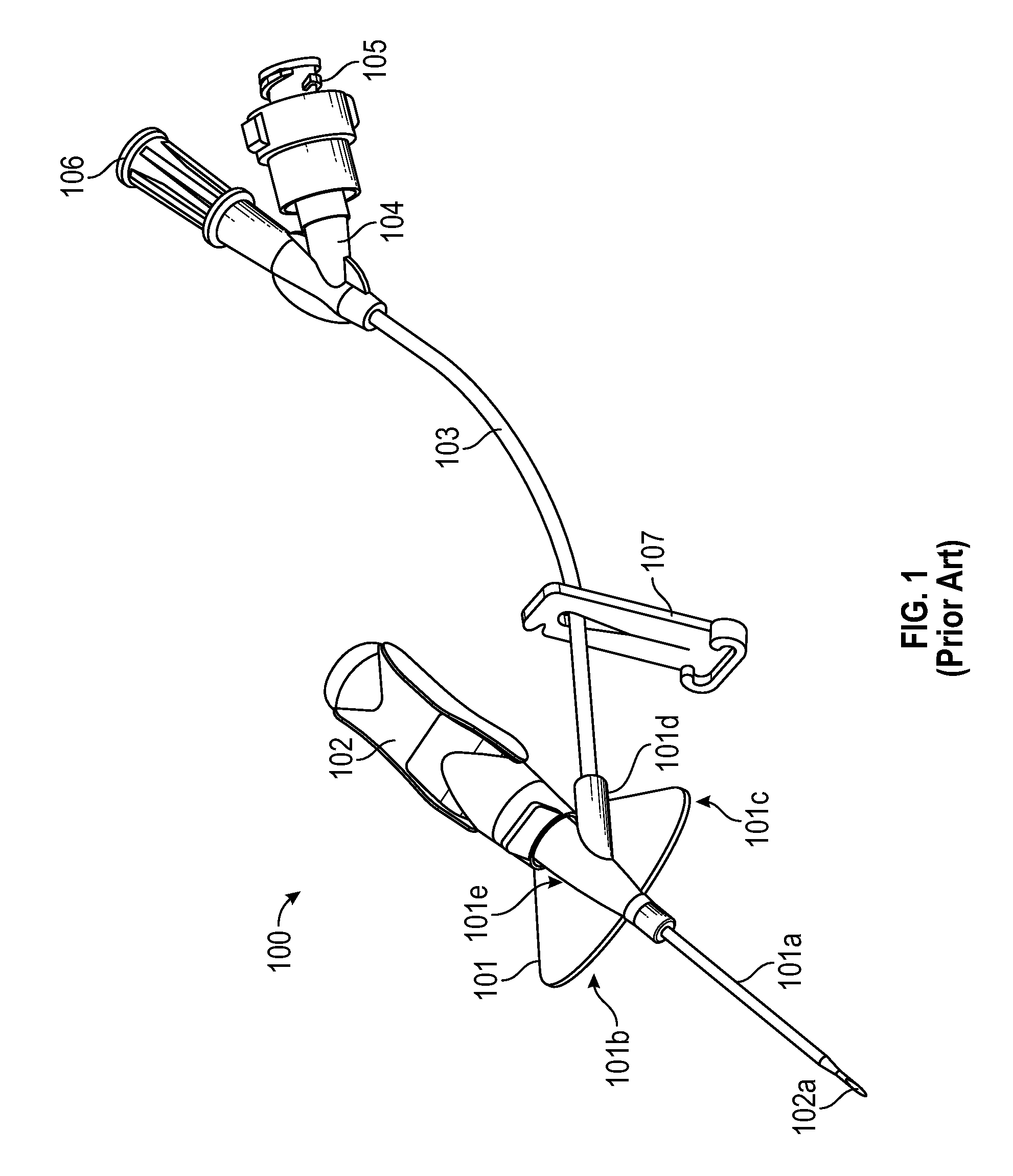
FIG. 1 illustrates an example of a prior art closed vascular access device 100. Device 100 includes a catheter adapter 101 from which a catheter 101a extends, a needle hub 102 from which a needle 102a extends, extension tubing 103 that is coupled to catheter adapter 101 at one end and includes a Y-adapter 104 coupled to the other end, and a clamp 107 for blocking or limiting fluid flow through extension tube 103. Y-adapter 104 includes a port 105 and a vent plug 106. Although a Y-adapter is shown, any type of luer adapter could be used. Device 100 can be a closed system by incorporating fluid flow blocking components (e.g., a septum or vent) into each external opening of the device such as into a proximal end of catheter adapter 101 and into any ports in adapter 104.
Catheter adapter 101 includes a stabilization platform that is comprised of a first side 101b and a second side 101c. Catheter adapter 101 also includes an extension 101d that extends from a main body portion 101e of catheter adapter 101. Access device 100 can be referred to as "integrated" because an end of extension tubing 103 inserts into and is secured within extension 101d such that extension tubing 103 is fluidly coupled to catheter 101a via a lumen of catheter adapter 101.
In access device 100, extension tubing 103 may kink at the interface between extension tubing 103 and extension 101d. Similarly, extension tubing 103 may also kink at the interface between extension tubing 103 and luer adapter 104.
BRIEF SUMMARY OF THE INVENTION
The present invention is generally directed to an integrated vascular access device that includes strain relief features to reduce the likelihood of the extension tubing becoming kinked during use. These strain relief features can be configured at both ends of the extension tubing to minimize the likelihood of kinking at the interfaces to the catheter adapter and luer adapter.
To provide strain relief at the catheter adapter end of the extension tubing, an extension of the catheter adapter into which the extension tubing inserts can be integrated into a side of a stabilization platform. Various components and/or surfaces of the present invention may comprise a soft, flexible material to assist the user in gripping the components, and/or to provide strain relief to a desired component. In some embodiments, a flexible material comprises a soft polymer having a durometer hardness of from approximately 30 Shore A to approximately 90 Shore D. In some embodiments, a flexible material comprises a soft polymer having a durometer hardness from approximately 50 Shore A to approximately 90 Shore D.
In some embodiments, the stabilization platform is formed of a flexible material. This flexible material can also be used to form an end portion of the extension. In this way, the end portion of the extension, which forms the interface between the extension tubing and the catheter adapter, is allowed to flex to minimize the likelihood that the extension tubing will become kinked. Alternatively, this interface can be formed separately from the stabilization platform including in embodiments where the catheter may or may not include a stabilization platform.
To provide strain relief at the luer adapter end of the extension tubing, a spacer comprising a flexible material can be positioned around the extension tubing and coupled to an end of the luer adapter. The flexible spacer therefore provides reinforcement at the interface between the extension tubing and the luer adapter and is allowed to flex to minimize the likelihood of kinking. In some embodiments, the flexible spacer can also be sized to block a clamp from extending overtop or contacting the rigid portion of the luer adapter. This further minimizes the likelihood of kinking due to the clamp bending against the luer adapter.
In one embodiment, the present invention is implemented as a vascular access device that includes: a catheter adapter comprising a main body portion from which a catheter extends distally and an extension that extends outwardly from the main body portion; extension tubing having a distal end that inserts into and is secured within the extension; and an interface formed of a flexible material that is positioned in-line with the extension such that the extension tubing extends through the interface and into the extension.
In another embodiment, the present invention is implemented as a vascular access device that includes: a catheter adapter; an adapter; extension tubing having a distal end coupled to the catheter adapter and a proximal end coupled to the adapter; and a flexible spacer having a proximal portion that is coupled to a distal end of the adapter and a distal portion that is positioned around the extension tubing.
In another embodiment, the present invention is implemented as a vascular access device that includes: a catheter adapter comprising a main body portion from which a catheter extends distally and an extension that extends outwardly from the main body portion; extension tubing having a distal end that inserts into and is secured within the extension; an adapter coupled to a proximal end of the extension tubing; and a first strain relief feature formed at a catheter adapter end of the extension tubing and a second strain relief feature formed at an adapter end of the extension tubing. The first and second strain relief feature are one of: an interface formed of a flexible material that is positioned in-line with the extension or a distal end of the adapter such that the extension tubing extends through the interface and into the extension or distal end of the adapter; or a flexible spacer having a first end that is coupled to the extension or distal end of the adapter and a second end that is positioned around the extension tubing.
These and other features and advantages of the present invention may be incorporated into certain embodiments of the invention and will become more fully apparent from the following description and appended claims, or may be learned by the practice of the invention as set forth hereinafter. The present invention does not require that all the advantageous features and all the advantages described herein be incorporated into every embodiment of the invention.
BRIEF DESCRIPTION OF THE SEVERAL VIEWS OF THE DRAWINGS
In order that the manner in which the above-recited and other features and advantages of the invention are obtained will be readily understood, a more particular description of the invention briefly described above will be rendered by reference to specific embodiments thereof that are illustrated in the appended drawings. These drawings depict only typical embodiments of the invention and are not therefore to be considered to limit the scope of the invention.
FIG. 1 illustrates a prior art IV access device.
FIG. 2 illustrates a vascular access device configured in accordance with one or more embodiments of the present invention.
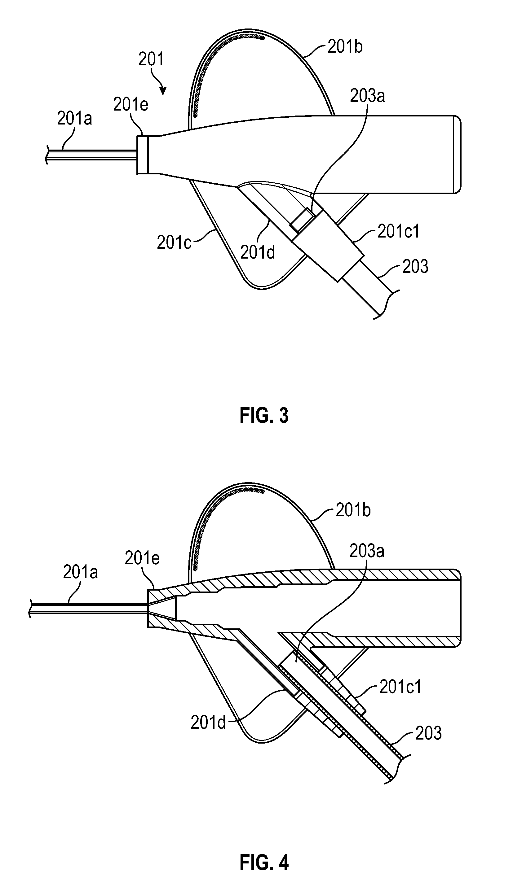
FIG. 3 illustrates a catheter adapter of the vascular access device shown in FIG. 2.
FIG. 4 provides a cross-sectional view of the catheter adapter shown in FIG. 3.
FIG. 5 provides a cross-sectional view of one embodiment of the luer adapter of the vascular access device shown in FIG. 2.
FIG. 6 provides a cross-sectional view of another embodiment of the luer adapter of the vascular access device shown in FIG. 2.
DETAILED DESCRIPTION OF THE INVENTION
FIG. 2 illustrates an example of a vascular access device 200 that is configured in accordance with one or more embodiments of the present invention. Access device 200 includes a catheter adapter 201 from which a catheter 201a extends distally, a needle hub 202 from which a needle 202a extends distally, extension tubing 203 having a distal end 203a that is coupled to catheter adapter 201 and a proximal end 203b coupled to an adapter 204, and a clamp 205 for restricting the flow of fluid through extension tubing 203. Adapter 204 can typically be a luer adapter which is configured to allow other access devices to be coupled to access device 200.
Catheter adapter 201 can include a stabilization platform formed by sides 201b and 201c which extend outwardly from opposite sides of catheter adapter 201. As shown in FIG. 2, in some embodiments access device 200 is configured for right-hand use in that extension tubing 203 couples to the left side of catheter adapter 201 such that stabilization platform side 201b is fully exposed. This can facilitate gripping stabilization platform side 201b with the thumb of the right hand. Of course, in an access device designed for left-hand use, stabilization platform sides 201b, 201c and extension tubing 203 would be on opposite sides of catheter adapter 201 from what is shown in FIG. 2.
Needle hub 202 includes a paddle grip 202b that extends outwardly from the right side of needle hub 202 and has a shape that generally corresponds to the shape of stabilization platform side 201b. Accordingly, paddle grip 202b can be positioned directly beneath stabilization platform side 201b so that stabilization platform side 201b and paddle grip 202b can be sandwiched between the clinician's thumb and index finger during insertion of catheter 201a. By configuring paddle grip 202b in this manner, the clinician can easily withdraw needle hub 202 from catheter adapter 201 by simply sliding the index finger backwards with respect to the thumb thereby causing the paddle grip 202b to slide backward away from stabilization platform side 201b.
Needle hub 202 also includes a flash chamber 210 that is coupled to the proximal end of needle hub 202. Flash chamber 210 can include a plug 210a that allows air to escape through a proximal opening in needle hub 202 while preventing blood from escaping. Also, a proximal end of needle 202a can extend into flash chamber 210 and can include an opening to allow blood to flow out of needle 202a and into flash chamber 210.
In accordance with embodiments of the present invention and as shown in FIGS. 3 and 4, a main body portion 201e of catheter adapter 201 can include an extension 201d that is integrated into stabilization platform side 201c. Extension 201d can be configured to receive and secure a distal end 203a of extension tubing 203. Both main body portion 201e and extension 201d can be molded from the same material.
Stabilization platform side 201c can be formed around (e.g., molded around) extension 201d in a manner that produces an interface 201c1 around extension tubing 203. Interface 201c1 can be (but is not required to be) formed of the same material as stabilization platform side 201c which is more flexible than the material used to form main body portion 201e and extension 201d. Once formed, interface 201c1 can function as an end portion of extension 201d. In other words, the combination of extension 201d and interface 201c1 can form a continuous structure through which distal end 203a of extension tubing 203 extends. One of skill in the art will appreciate that interface 201c1 may be incorporated into any stabilization platform of any compatible catheter adapter comprising an integrated extension tube and respective extension. For example, in one embodiment interface 201c1 may be incorporated into or onto extension 101d of prior art device 100 of FIG. 1.
Because interface 201c1 is formed of a more flexible material than extension 201d, kinking is less likely to occur at the interface between extension tubing 203 and extension 201d. In particular, extension tubing 203 can be formed of a material that is substantially flexible to allow adapter 204 to be positioned at any suitable location with respect to catheter adapter 201. Interface 201c1 (as well as stabilization platform side 201c) can be less flexible than extension tubing 203 but more flexible than extension 201d so that the portion of extension tubing 203 within interface 201c1 can bend to some degree, but not enough to form a kink. This transition in flexibility substantially reduces the likelihood that extension tubing 203 will kink.
FIG. 4 provides a cross-sectional view of catheter adapter 201. In this figure, the cross-section is taken along a plane that is just above the top surface of stabilization platform sides 201b and 201c and that extends through main body portion 201e and extension 201d. As shown, main body portion 201e and extension 201d can be molded as a single component. Stabilization platform side 201b, stabilization platform side 201c, and interface 201c1 may also be molded as a single component around catheter adapter 201. Alternatively, stabilization platform side 201c and interface 201c1 could be molded as a single component that is separate from stabilization platform side 201b. In either case, interface 201c1 is an integral portion of stabilization platform side 201c that forms a sleeve-like structure through which extension tubing 203c extends. FIG. 4 also shows that the distal end 203a of extension tubing 203 inserts into extension 201d so that it is secured to catheter adapter 201. Extension 201d and interface 201c1 can therefore form a continuous lumen through which extension tubing 203 inserts.
In other embodiments, interface 201c1 may be formed independently of a stabilization platform. For example, interface 201c1 could be molded around or against extension 201d independently of (e.g., above) stabilization platform side 201b. Alternatively, interface 201c1 could be molded around or against extension 201d on catheter adapters that do not include a stabilization platform or that include only a stabilization platform side on an opposite side of the catheter adapter (e.g., only stabilization platform side 201b).
It is noted that needle hub 202 is not shown in FIGS. 3 and 4. Also, catheter adapter 201 may typically include a septum (not shown) positioned proximal to extension 201d to prevent blood or fluid from flowing proximally out through the proximal opening of catheter adapter 201. Extension 201d is shown as not extending up to or beyond an edge of stabilization platform side 201c. However, in some embodiments, extension 201d may extend farther than what is shown in FIGS. 3 and 4. For example, extension 201d could extend up to and even beyond the edge of stabilization platform side 201c. In such cases, interface 201c1 could be configured to encapsulate a portion of extension 201d as well as to extend beyond an edge of extension 201d in the manner shown in FIGS. 3 and 4.
FIGS. 5 and 6 illustrate cross-sectional views of embodiments of a luer adapter 204 that includes a flexible spacer 206. As shown, a proximal end 203b of extension tubing 203 extends into and is secured within luer adapter 204. Flexible spacer 206 has a sleeve shape with an inner diameter that is sufficient to allow flexible spacer 206 to be placed around extension tubing 203. Flexible spacer 206 can also be sufficiently elastic to allow a proximal portion 206b to be placed around a distal end of luer adapter 204. With proximal portion 206b placed around luer adapter 204, flexible spacer 206 will be secured to luer adapter 204 with a distal portion 206a being positioned around extension tubing 203. Distal portion 206a can provide reinforcement at the interface between luer adapter 204 and extension tubing 203 thereby minimizing the likelihood that extension tubing 203 will become kinked at the interface.
In some embodiments, such as is shown in FIGS. 5 and 6, the distal opening of luer adapter 204 can include a chamfered surface 204a. Chamfered surface 204a allows extension tubing 203 to bend slightly prior to contacting the distal edge of luer adapter 204. As shown in FIG. 6, in some embodiments, the inner diameter of flexible spacer 206 can be greater than the outer diameter of extension tubing 203 and substantially equal to the diameter at the distalmost point of chamfered surface 204a. In such cases, a space 206a1 will exist between extension tubing 203 and distal portion 206a.
Flexible spacer 206 can be a separate component from extension tubing 203 and luer adapter 204. As a separate component, flexible spacer 206 can be formed of a suitable elastic material that is different than the material used to form luer adapter 204. In some embodiments, flexible spacer 206 can have an outer diameter that is greater than an inner diameter of the channel or opening in clamp 205 through which extension tubing 203 extends. In this way, flexible spacer 206 can function to prevent clamp 205 from being positioned too close to luer adapter 204. In particular, if clamp 205 clamps extension tubing 203 at the interface between extension tubing 203 and luer adapter 206, it would cause extension tubing 203 to be more likely to kink at the interface when it is bent against the distal end of the luer adapter 204. Flexible spacer 206 can also be employed to ensure that clamp 205 cannot clamp extension tubing 203 near the interface.
Although the above description describes forming interface 201c1 only at the catheter adapter end of the extension tubing and describes incorporating flexible spacer 206 only at the luer adapter end of the extension tubing, these techniques could be applied on the opposite ends of the extension tubing. For example, an interface similar to interface 201c1 could be formed on a distal end of luer adapter 204 around extension tubing 203 in place of flexible spacer 206. This could be accomplished by separately molding an interface from a flexible material around the distal end of luer adapter 204 (e.g., with reference to the figures, extension 201d could be viewed as the distal end of luer adapter 204). Alternatively, in embodiments where luer adapter 204 includes a component that is molded of a flexible material, the interface could be integrally formed within the component in a similar manner as interface 201c1 can be integrally formed within stabilization platform side 201c. For example, if luer adapter 204 includes a soft grip feature, this soft grip feature could be extended to form an interface at the distal end of luer adapter 204.
Similarly, a flexible spacer could be employed at the catheter adapter end of the extension tubing in place of interface 201c1. This could be accomplished by placing a distal portion of a flexible spacer around (or otherwise secured to) extension 201d. In such cases, extension 201d could be configured with a chamfer similar to what is shown in FIGS. 5 and 6. As described above, a flexible spacer could be employed in this manner in any configuration of a catheter adapter that includes extension 201d including those with or without a stabilization platform.
Various embodiments of the present invention further comprise a safety mechanism configured to secure the sharpened, distal tip of the introducer needle following removal and separation of the needle hub from the catheter adapter. A safety mechanism may include any compatible device known in the art. In some instances, the safety mechanism is configured to interact with a needle feature, such as a ferrule, notch, crimp or bump on the cannula. The crimp or bump formed in the cannula causes a slight out of round configuration that can be used to activate a safety mechanism. In some instance, the safety mechanism comprises an arm or lever that is actuated to capture the needle tip within the mechanism and prevent the tip from emerging prior to safe disposal.
The safety mechanism is attached to the body of the needle and is capable of sliding along the length thereof. In some instances, an initial or assembled position of the safety mechanism is located in proximity to the base or proximal end of the catheter adapter prior to catheterization. For some configurations, the assembled position of the safety mechanism is between the proximal end of the needle hub and the proximal end of the catheter adapter or stabilization platform, wherein the safety mechanism does not overlap the catheter adapter or stabilization platform. In some instances, a portion of the safety mechanism is positioned within the catheter adapter, with the balance of the safety mechanism being positioned external to the catheter adapter, such as within the needle hub. In some embodiments, a portion of the catheter adapter or stabilization platform is extended proximally to provide a housing in which at least a portion of the safety mechanism is housed. In some instances, the entire safety mechanism is housed within the housing of the catheter adapter or stabilization platform prior to catheterization.
In some embodiments, the assembled position of the safety mechanism positions the proximal end of the catheter adapter between the distal end of the safety mechanism and a distal end of a paddle grip of the needle hub. In some instances, the assembled position of the safety mechanism positions the proximal end of the catheter adapter between the distal end of the safety mechanism and a proximal end of a paddle grip of the needle hub. In some instances, a portion of the safety mechanism overlaps a portion of a paddle grip of the needle hub. In some embodiments, at least some portion of at least one of the catheter adapter and the paddle grip overlaps at least some portion of the safety mechanism. In some embodiments, no portion of the catheter adapter or paddle grip overlaps any portion of the safety mechanism.
In some embodiments, a defeatable mechanical connection is provided between the safety mechanism and at least one other component of the access device. In some embodiments, a distal end of the safety mechanism is selectively coupled to a proximal end of the catheter adapter. In one embodiment, the safety mechanism interlocks internally to the proximal end of the catheter adapter. In one embodiment, the safety mechanism interlocks externally to the proximal end of the catheter adapter. In some embodiments, a distal end of the safety mechanism is selectively coupled to a proximal end of the stabilization platform. In some embodiments, a surface of the safety mechanism is selectively coupled to at least one surface of at least one of the catheter adapter, a blood control valve, an extension tube, and the stabilization platform. In some instances, the mechanical connection is defeated upon securement of the needle tip within the safety mechanism.
The present invention may be embodied in other specific forms without departing from its structures, methods, or other essential characteristics as broadly described herein and claimed hereinafter. The described embodiments are to be considered in all respects only as illustrative, and not restrictive. The scope of the invention is, therefore, indicated by the appended claims, rather than by the foregoing description. All changes that come within the meaning and range of equivalency of the claims are to be embraced within their scope.
* * * * *
References
-
sageproducts.com/products/ssi-prevention.cfm
-
enturia.com/products/chloraPrep/chloraPrep-product.html
-
conquimica.com/wp-content/uploads/2015/06/ft_irgacure_500.pdf
-
gamahealthcare.com/clinellaca2c.html
-
dsm.com/en_US/medical/public/home/pages/product-coating-comfortcoat.jsp
-
harlandmedical.com/index.php/materials/lubricent.html
-
-
-
cabot-corp.com/Silicas-And-Aluminas/Coatings
-
xiperinnovations.com/uv-eb-cure
D00000
D00001
D00002
D00003
D00004
XML
uspto.report is an independent third-party trademark research tool that is not affiliated, endorsed, or sponsored by the United States Patent and Trademark Office (USPTO) or any other governmental organization. The information provided by uspto.report is based on publicly available data at the time of writing and is intended for informational purposes only.
While we strive to provide accurate and up-to-date information, we do not guarantee the accuracy, completeness, reliability, or suitability of the information displayed on this site. The use of this site is at your own risk. Any reliance you place on such information is therefore strictly at your own risk.
All official trademark data, including owner information, should be verified by visiting the official USPTO website at www.uspto.gov. This site is not intended to replace professional legal advice and should not be used as a substitute for consulting with a legal professional who is knowledgeable about trademark law.