Bone implant and means of insertion
Hartdegen , et al. De
U.S. patent number 10,492,841 [Application Number 15/324,393] was granted by the patent office on 2019-12-03 for bone implant and means of insertion. This patent grant is currently assigned to CROSSROADS EXTREMITY SYSTEMS, LLC. The grantee listed for this patent is CROSSROADS EXTREMITY SYSTEMS, LLC. Invention is credited to Vernon R. Hartdegen, Michael Chad Hollis.


View All Diagrams
| United States Patent | 10,492,841 |
| Hartdegen , et al. | December 3, 2019 |
Bone implant and means of insertion
Abstract
An assembly used in osteosynthesis comprising a delivery instrument in combination with an implant wherein the delivery instrument releasably holds the implant in a first configuration prior to attachment of the implant to bone. The delivery instrument allows the implant to be affixed to bone before the implant is released from the instrument. And the instrument may comprise guide means for drills, depth gauges, screws, pins, pegs, blades and or drivers which are used or implanted when the implant is releasably attached to the instrument. After the implant is affixed to bone and released from the delivery instrument, the implant assumes at least a second configuration which provides compression and or distraction and or control of spacial orientation.
| Inventors: | Hartdegen; Vernon R. (Collierville, TN), Hollis; Michael Chad (Collierville, TN) | ||||||||||
|---|---|---|---|---|---|---|---|---|---|---|---|
| Applicant: |
|
||||||||||
| Assignee: | CROSSROADS EXTREMITY SYSTEMS,
LLC (Memphis, TN) |
||||||||||
| Family ID: | 55064832 | ||||||||||
| Appl. No.: | 15/324,393 | ||||||||||
| Filed: | July 8, 2015 | ||||||||||
| PCT Filed: | July 08, 2015 | ||||||||||
| PCT No.: | PCT/US2015/039551 | ||||||||||
| 371(c)(1),(2),(4) Date: | January 06, 2017 | ||||||||||
| PCT Pub. No.: | WO2016/007624 | ||||||||||
| PCT Pub. Date: | January 14, 2016 |
Prior Publication Data
| Document Identifier | Publication Date | |
|---|---|---|
| US 20170196604 A1 | Jul 13, 2017 | |
Related U.S. Patent Documents
| Application Number | Filing Date | Patent Number | Issue Date | ||
|---|---|---|---|---|---|
| 62022811 | Jul 10, 2014 | ||||
| Current U.S. Class: | 1/1 |
| Current CPC Class: | A61B 17/0682 (20130101); A61B 17/1739 (20130101); A61B 17/8085 (20130101); A61B 17/0642 (20130101); A61B 17/8061 (20130101); A61B 17/8863 (20130101); A61B 17/1728 (20130101); A61B 17/8052 (20130101); A61B 17/1775 (20161101); A61B 17/808 (20130101); A61B 2017/00867 (20130101); A61B 2017/0645 (20130101) |
| Current International Class: | A61B 17/80 (20060101); A61B 17/068 (20060101); A61B 17/17 (20060101); A61B 17/064 (20060101) |
References Cited [Referenced By]
U.S. Patent Documents
| 2010913 | August 1935 | Bruce |
| 2133859 | October 1938 | Hawley |
| 2544492 | March 1951 | Downing |
| 2811073 | October 1957 | Klopstock |
| 3741205 | June 1973 | Markolf |
| 4263903 | April 1981 | Griggs |
| 4278091 | July 1981 | Borzone |
| 4415111 | November 1983 | McHarrie |
| 4438769 | March 1984 | Pratt |
| 4454875 | June 1984 | Pratt |
| 4484570 | November 1984 | Sutter |
| 4655222 | April 1987 | Florez |
| 4805617 | February 1989 | Bedi |
| 4848328 | July 1989 | Laboureau |
| 4852558 | August 1989 | Outerbridge |
| 5013315 | May 1991 | Barrows |
| 5044540 | September 1991 | Dulebohn |
| 5209756 | May 1993 | Seedhom |
| 5246443 | September 1993 | Mai |
| 5258012 | November 1993 | Luscombe |
| 5352229 | October 1994 | Goble |
| 5395372 | March 1995 | Holt |
| 5449359 | September 1995 | Groiso |
| 5454814 | October 1995 | Comte |
| 5490409 | February 1996 | Weber |
| 5498749 | March 1996 | Heise |
| 5520700 | May 1996 | Beyar |
| 5578034 | November 1996 | Estes |
| 5607425 | March 1997 | Rogozinski |
| 5628740 | May 1997 | Mullane |
| 5634926 | June 1997 | Jobe |
| 5660188 | August 1997 | Groiso |
| 5662655 | September 1997 | Laboureau |
| 5716357 | February 1998 | Rogozinski |
| 5749564 | May 1998 | Malek |
| 5779707 | July 1998 | Bertholet |
| 5785713 | July 1998 | Jobe |
| 5788698 | August 1998 | Savornin |
| 5807403 | September 1998 | Beyar |
| 5853414 | December 1998 | Groiso |
| 5904682 | May 1999 | Rogozinski |
| 5931839 | August 1999 | Medoff |
| 5947968 | September 1999 | Rogozinski |
| 5947999 | September 1999 | Groiso |
| 5972000 | October 1999 | Beyar |
| 5993476 | November 1999 | Groiso |
| 6010504 | January 2000 | Rogozinski |
| 6017343 | January 2000 | Rogozinski |
| 6019759 | February 2000 | Rogozinski |
| 6059787 | May 2000 | Allen |
| 6089435 | July 2000 | Malek |
| 6105936 | August 2000 | Malek |
| 6179840 | January 2001 | Bowman |
| 6187009 | February 2001 | Herzog |
| 6281262 | August 2001 | Shikinami |
| 6322562 | November 2001 | Wolter |
| 6334446 | January 2002 | Beyar |
| 6336927 | January 2002 | Rogozinski |
| 6348054 | February 2002 | Allen |
| 6364884 | April 2002 | Bowman |
| 6379354 | April 2002 | Rogozinski |
| 6387041 | May 2002 | Harari |
| 6402765 | June 2002 | Monassevitch |
| 6402766 | June 2002 | Bowman |
| 6406480 | June 2002 | Beyar |
| 6423073 | July 2002 | Bowman |
| 6436110 | August 2002 | Bowman |
| 6447517 | September 2002 | Bowman |
| 6497707 | December 2002 | Bowman |
| 6544273 | April 2003 | Harari |
| 6575984 | June 2003 | Beyar |
| 6575998 | June 2003 | Beyar |
| 6582435 | June 2003 | Wellisz |
| 6592610 | July 2003 | Beyar |
| 6635058 | October 2003 | Beyar |
| 6652531 | November 2003 | Wellisz |
| 6663642 | December 2003 | Beyar |
| 6679885 | January 2004 | Wellisz |
| 6709437 | March 2004 | Wellisz |
| 6730110 | May 2004 | Harari |
| 6746455 | June 2004 | Beyar |
| 6783531 | August 2004 | Allen |
| 6896684 | May 2005 | Monassevitch |
| 6966911 | November 2005 | Groiso |
| 6974461 | December 2005 | Wolter |
| 7044951 | May 2006 | Medoff |
| 7090676 | August 2006 | Huebner |
| 7147640 | December 2006 | Huebner |
| 7153309 | December 2006 | Huebner |
| 7179260 | February 2007 | Gerlach |
| 7189237 | March 2007 | Huebner |
| 7214232 | May 2007 | Bowman |
| 7226408 | June 2007 | Harai |
| 7229452 | June 2007 | Kayan |
| 7235079 | June 2007 | Jensen |
| 7250054 | July 2007 | Allen |
| 7255701 | August 2007 | Allen |
| 7311712 | December 2007 | Dalton |
| 7326212 | February 2008 | Huebner |
| 7438209 | October 2008 | Hess |
| 7473257 | January 2009 | Knopfle |
| 7500979 | March 2009 | Hueil |
| 7506791 | March 2009 | Omaits |
| 7537596 | May 2009 | Jensen |
| 7537603 | May 2009 | Huebner |
| 7537604 | May 2009 | Huebner |
| 7556647 | July 2009 | Drews |
| 7578825 | August 2009 | Huebner |
| 7604151 | October 2009 | Hess |
| 7618441 | November 2009 | Groiso |
| 7651498 | January 2010 | Shifrin |
| 7665647 | February 2010 | Shelton, IV |
| 7669746 | March 2010 | Shelton, IV |
| 7669747 | March 2010 | Weisenburgh, II |
| 7673781 | March 2010 | Swayze |
| 7673782 | March 2010 | Hess |
| 7704251 | April 2010 | Huebner |
| 7704279 | April 2010 | Moskowitz |
| 7717945 | May 2010 | Jensen |
| 7735703 | June 2010 | Morgan |
| 7740634 | June 2010 | Orbay |
| 7766209 | August 2010 | Baxter, III |
| 7766948 | August 2010 | Leung |
| 7771433 | August 2010 | Orbay |
| 7794475 | September 2010 | Hess |
| 7832612 | November 2010 | Baxter, III |
| 7846188 | December 2010 | Moskowitz |
| 7857186 | December 2010 | Baxter, III |
| 7857836 | December 2010 | Huebner |
| 7867265 | January 2011 | Beutter |
| 7905381 | March 2011 | Baxter, III |
| 7905910 | March 2011 | Gerlach |
| 7909858 | March 2011 | Gerlach |
| 7914532 | March 2011 | Shaver |
| 7918879 | April 2011 | Yeung |
| 7927332 | April 2011 | Huebner |
| 7934630 | May 2011 | Shelton, IV |
| 7935126 | May 2011 | Orbay |
| 7942903 | May 2011 | Moskowitz |
| 7951180 | May 2011 | Moskowitz |
| 7954686 | June 2011 | Baxter, III |
| 7955388 | June 2011 | Jensen |
| 7963982 | June 2011 | Kirschman |
| 7966799 | June 2011 | Morgan |
| 7972363 | July 2011 | Moskowitz |
| 8016867 | September 2011 | Bowman |
| 8043346 | October 2011 | Markworth |
| 8100953 | January 2012 | White |
| 8105367 | January 2012 | Austin |
| 8114139 | February 2012 | Sournac |
| 8137351 | March 2012 | Prandi |
| 8141762 | March 2012 | Bedi |
| 8172886 | May 2012 | Castaneda |
| 8177819 | May 2012 | Huebner |
| 8182518 | May 2012 | Butler |
| 8186560 | May 2012 | Hess |
| 8205781 | June 2012 | Baxter, III |
| 8220690 | July 2012 | Hess |
| 8231627 | July 2012 | Huebner |
| 8231662 | July 2012 | Huebner |
| 8241326 | August 2012 | Harari |
| 8241338 | August 2012 | Castaneda |
| 8252032 | August 2012 | White |
| 8257370 | September 2012 | Moskowitz |
| 8262711 | September 2012 | Hess |
| 8317070 | November 2012 | Hueil |
| 8348129 | January 2013 | Bedi |
| 8348131 | January 2013 | Omaits |
| 8353913 | January 2013 | Moskowitz |
| 8360297 | January 2013 | Shelton, IV |
| 8365976 | February 2013 | Hess |
| 8382807 | February 2013 | Austin |
| 8393517 | March 2013 | Milo |
| 8398717 | March 2013 | Kleinman |
| 8413872 | April 2013 | Patel |
| 8425574 | April 2013 | Huebner |
| 8425575 | April 2013 | Huebner |
| 8425576 | April 2013 | Anderson |
| 8430292 | April 2013 | Patel |
| 8449561 | May 2013 | Bowman |
| 8453908 | June 2013 | Bedi |
| 8464923 | June 2013 | Shelton, IV |
| 8475504 | July 2013 | Gillard |
| 8485412 | July 2013 | Shelton, IV |
| 8486116 | July 2013 | Heilman |
| 8496693 | July 2013 | Robinson |
| 8499993 | August 2013 | Shelton, IV |
| 8518090 | August 2013 | Huebner |
| 8523919 | September 2013 | Huebner |
| 8540129 | September 2013 | Baxter, III |
| 8540133 | September 2013 | Bedi |
| 8545540 | October 2013 | Castaneda |
| 8561870 | October 2013 | Baxter, III |
| 8567656 | October 2013 | Shelton, IV |
| 8574270 | November 2013 | Hess |
| 8584853 | November 2013 | Knight |
| 8585743 | November 2013 | Ampuero |
| 8590762 | November 2013 | Hess |
| 8596514 | December 2013 | Miller |
| 8603161 | December 2013 | Drews |
| 8636187 | January 2014 | Hueil |
| 8652142 | February 2014 | Geissler |
| 8652180 | February 2014 | Federspiel |
| 8668130 | March 2014 | Hess |
| 8672208 | March 2014 | Hess |
| 8672828 | March 2014 | Harari |
| 8679123 | March 2014 | Kinmon |
| 8720766 | May 2014 | Hess |
| 8727197 | May 2014 | Hess |
| 8728128 | May 2014 | Hawkes |
| 8728129 | May 2014 | Fritzinger |
| 8734516 | May 2014 | Moskowitz |
| 8740915 | June 2014 | Niederberger |
| 8747444 | June 2014 | Moskowitz |
| 8763875 | July 2014 | Morgan |
| 8777969 | July 2014 | Kayan |
| 8779927 | July 2014 | Bell |
| 8784450 | July 2014 | Moskowitz |
| 8800838 | August 2014 | Shelton, IV |
| 8808325 | August 2014 | Hess |
| 8808335 | August 2014 | Biedermann |
| 8814915 | August 2014 | Hess |
| 8834537 | September 2014 | Castaneda |
| 8858562 | October 2014 | Orbay |
| 8870882 | October 2014 | Kleiner |
| 8882812 | November 2014 | Hess |
| 8888824 | November 2014 | Austin |
| 8888826 | November 2014 | Kinmon |
| 8894651 | November 2014 | Aflatoon |
| 8899465 | December 2014 | Shelton, IV |
| 8906046 | December 2014 | Anderson |
| 8925788 | January 2015 | Hess |
| 8940028 | January 2015 | Austin |
| 8973804 | March 2015 | Hess |
| 8974504 | March 2015 | Hess |
| 8986305 | March 2015 | Aflatoon |
| 8991676 | March 2015 | Hess |
| 8992581 | March 2015 | Austin |
| 9005206 | April 2015 | Ampuero |
| 9005293 | April 2015 | Moskowitz |
| 9017331 | April 2015 | Fox |
| 9017380 | April 2015 | Mayer |
| 9034037 | May 2015 | Fiere |
| 9072554 | July 2015 | Reynolds |
| 9078757 | July 2015 | Kleinman |
| 9095338 | August 2015 | Taylor |
| 9095388 | August 2015 | Hess |
| 9101349 | August 2015 | Knight |
| 9107661 | August 2015 | Euteneuer |
| 9125650 | September 2015 | Euteneuer |
| 9138233 | September 2015 | Anderson |
| 9179911 | November 2015 | Morgan |
| 9180022 | November 2015 | Georges |
| 9204932 | December 2015 | Knight |
| 9220515 | December 2015 | Castaneda |
| 9237891 | January 2016 | Shelton, IV |
| 9247978 | February 2016 | Euteneuer |
| 9265649 | February 2016 | Pflueger |
| D752219 | March 2016 | Peterson |
| 9271726 | March 2016 | Euteneuer |
| 9283006 | March 2016 | Fonte |
| 9289206 | March 2016 | Hess |
| 9289210 | March 2016 | Baxter, III |
| 9301854 | April 2016 | Moskowitz |
| 9307988 | April 2016 | Shelton, IV |
| 9308033 | April 2016 | Huebner |
| 9326768 | May 2016 | Shelton, IV |
| 9326771 | May 2016 | Baxter, III |
| 9339268 | May 2016 | Fox |
| 9370355 | June 2016 | Anderson |
| 9370356 | June 2016 | Euteneuer |
| 9370376 | June 2016 | Castaneda |
| 9387116 | July 2016 | Pflueger |
| 9402623 | August 2016 | Kayan |
| 9402624 | August 2016 | Scott |
| 9408603 | August 2016 | Patel |
| 9408604 | August 2016 | Shelton, IV |
| 9408647 | August 2016 | Cheney |
| 9414841 | August 2016 | Euteneuer |
| 9414871 | August 2016 | Huebner |
| 9421013 | August 2016 | Patel |
| 9445808 | September 2016 | Woodard, Jr. |
| 9451957 | September 2016 | Fox |
| 9463015 | October 2016 | Hausen |
| 9486212 | November 2016 | Miller |
| 9532821 | January 2017 | Moskowitz |
| 9539023 | January 2017 | Marotte |
| 9549735 | January 2017 | Shelton, IV |
| 9561032 | February 2017 | Shelton, IV |
| 9566063 | February 2017 | Euteneuer |
| 9603641 | March 2017 | Hulliger |
| 9615856 | April 2017 | Arnett |
| 9763715 | September 2017 | Mather |
| 9839458 | December 2017 | Bouduban |
| 9861404 | January 2018 | Reiley |
| 9955964 | May 2018 | Mayer |
| 10166022 | January 2019 | Early |
| 10292743 | May 2019 | Taylor |
| 10299842 | May 2019 | Hollis |
| 2001/0028148 | October 2001 | White |
| 2002/0035369 | March 2002 | Beyar |
| 2002/0095181 | July 2002 | Beyar |
| 2002/0111641 | August 2002 | Peterson |
| 2002/0173793 | November 2002 | Allen |
| 2002/0177859 | November 2002 | Monassevitch |
| 2003/0083663 | May 2003 | Goldhahn |
| 2003/0100899 | May 2003 | Wellisz |
| 2003/0100900 | May 2003 | Wellisz |
| 2003/0100901 | May 2003 | Wellisz |
| 2003/0100902 | May 2003 | Wellisz |
| 2003/0139746 | July 2003 | Groiso |
| 2003/0158553 | August 2003 | Michelson |
| 2003/0225409 | December 2003 | Freid |
| 2004/0073222 | April 2004 | Koseki |
| 2004/0127896 | July 2004 | Lombardo |
| 2004/0133214 | July 2004 | Kayan |
| 2004/0172040 | September 2004 | Heggeness |
| 2004/0176780 | September 2004 | Knopfle |
| 2004/0220570 | November 2004 | Frigg |
| 2005/0021032 | January 2005 | Koo |
| 2005/0021035 | January 2005 | Groiso |
| 2005/0043757 | February 2005 | Arad |
| 2005/0049600 | March 2005 | Groiso |
| 2005/0080454 | April 2005 | Drews |
| 2005/0085818 | April 2005 | Huebner |
| 2005/0096660 | May 2005 | Allen |
| 2005/0101961 | May 2005 | Huebner |
| 2005/0107796 | May 2005 | Gerlach |
| 2005/0119667 | June 2005 | Leport |
| 2005/0165400 | July 2005 | Fernandez |
| 2005/0171544 | August 2005 | Falkner |
| 2005/0234458 | October 2005 | Huebner |
| 2005/0240187 | October 2005 | Huebner |
| 2006/0058796 | March 2006 | Hartdegen |
| 2006/0058802 | March 2006 | Kofoed |
| 2006/0106391 | May 2006 | Huebner |
| 2006/0122604 | June 2006 | Gorhan |
| 2006/0122605 | June 2006 | Suh et al. |
| 2006/0129151 | June 2006 | Allen |
| 2006/0161161 | July 2006 | Shifrin |
| 2006/0200147 | September 2006 | Ensign |
| 2006/0241612 | October 2006 | Medoff |
| 2006/0241618 | October 2006 | Gasser |
| 2006/0264936 | November 2006 | Partin |
| 2007/0055249 | March 2007 | Jensen |
| 2007/0173840 | July 2007 | Huebner |
| 2007/0208358 | September 2007 | Kayan |
| 2007/0233116 | October 2007 | Olerud |
| 2008/0147125 | June 2008 | Colleran |
| 2008/0167666 | July 2008 | Fiere |
| 2008/0195099 | August 2008 | Minas |
| 2008/0200955 | August 2008 | Tepic |
| 2008/0255620 | October 2008 | Strauss |
| 2008/0275510 | November 2008 | Schonhardt |
| 2008/0288000 | November 2008 | Cawley |
| 2008/0319443 | December 2008 | Focht |
| 2009/0018556 | January 2009 | Prandi |
| 2009/0054930 | February 2009 | Aflatoon |
| 2009/0099602 | April 2009 | Aflatoon |
| 2009/0138082 | May 2009 | Reah |
| 2009/0177203 | July 2009 | Reiley |
| 2009/0182383 | July 2009 | Prybyla |
| 2009/0254090 | October 2009 | Lizee |
| 2009/0254126 | October 2009 | Orbay |
| 2009/0281543 | November 2009 | Orbay |
| 2009/0287249 | November 2009 | Reynolds |
| 2010/0036430 | February 2010 | Hartdegen |
| 2010/0076448 | March 2010 | Abdou |
| 2010/0082065 | April 2010 | Butler |
| 2010/0100138 | April 2010 | Reynolds |
| 2010/0106196 | April 2010 | Erickson |
| 2010/0125275 | May 2010 | Kinmon |
| 2010/0133316 | June 2010 | Lizee |
| 2010/0211116 | August 2010 | Suh |
| 2010/0237128 | September 2010 | Miller |
| 2010/0256765 | October 2010 | Butler |
| 2010/0292715 | November 2010 | Nering |
| 2010/0312280 | December 2010 | Overes |
| 2011/0022049 | January 2011 | Huebner |
| 2011/0022099 | January 2011 | Ashman |
| 2011/0029016 | February 2011 | Yeung |
| 2011/0029023 | February 2011 | Tornier |
| 2011/0029025 | February 2011 | Medoff |
| 2011/0054542 | March 2011 | Kevin |
| 2011/0092981 | April 2011 | Ng |
| 2011/0098754 | April 2011 | Hulliger |
| 2011/0118742 | May 2011 | Hulliger |
| 2011/0118796 | May 2011 | Reiley |
| 2011/0118840 | May 2011 | Huntsman |
| 2011/0178522 | July 2011 | Orbay |
| 2011/0202092 | August 2011 | Frigg |
| 2011/0270326 | November 2011 | Black |
| 2011/0282393 | November 2011 | Gerlach |
| 2011/0295324 | December 2011 | Donley |
| 2011/0313421 | December 2011 | Sidebotham |
| 2011/0319942 | December 2011 | Bottlang |
| 2012/0022600 | January 2012 | Overes |
| 2012/0024937 | February 2012 | Allen |
| 2012/0053638 | March 2012 | Rusch |
| 2012/0059425 | March 2012 | Biedermann |
| 2012/0065690 | March 2012 | Perrow |
| 2012/0078371 | March 2012 | Gamache |
| 2012/0085809 | April 2012 | Milo |
| 2012/0095513 | April 2012 | Humphreys |
| 2012/0130374 | May 2012 | Bouduban |
| 2012/0136396 | May 2012 | Baker |
| 2012/0143193 | June 2012 | Hulliger |
| 2012/0150240 | June 2012 | Medoff |
| 2012/0179207 | July 2012 | Mekhail |
| 2012/0191141 | July 2012 | Costabile |
| 2012/0323284 | December 2012 | Baker |
| 2013/0006247 | January 2013 | Weiner |
| 2013/0023938 | January 2013 | Huebner |
| 2013/0023940 | January 2013 | Hansell |
| 2013/0026206 | January 2013 | Fox |
| 2013/0026207 | January 2013 | Fox |
| 2013/0030437 | January 2013 | Fox |
| 2013/0030438 | January 2013 | Fox |
| 2013/0046346 | February 2013 | Thorwarth |
| 2013/0109910 | May 2013 | Alexander |
| 2013/0138154 | May 2013 | Reiley |
| 2013/0150900 | June 2013 | Haddad |
| 2013/0153627 | June 2013 | Euteneuer |
| 2013/0206815 | August 2013 | Fox |
| 2013/0213843 | August 2013 | Knight |
| 2013/0218285 | August 2013 | Kleinman |
| 2013/0231667 | September 2013 | Taylor |
| 2013/0238035 | September 2013 | Medoff |
| 2013/0267956 | October 2013 | Terrill |
| 2013/0303071 | November 2013 | Seki |
| 2013/0325074 | December 2013 | Ziolo |
| 2013/0345752 | December 2013 | Hendren |
| 2014/0014548 | January 2014 | Knight |
| 2014/0014553 | January 2014 | Knight |
| 2014/0018809 | January 2014 | Allen |
| 2014/0018862 | January 2014 | Koay |
| 2014/0020333 | January 2014 | Knight |
| 2014/0024002 | January 2014 | Knight |
| 2014/0034702 | February 2014 | Miller |
| 2014/0058461 | February 2014 | Black |
| 2014/0097228 | April 2014 | Taylor |
| 2014/0100652 | April 2014 | Drews |
| 2014/0142628 | May 2014 | Traynelis |
| 2014/0163621 | June 2014 | Huebner |
| 2014/0163682 | June 2014 | Iott |
| 2014/0163683 | June 2014 | Seifert |
| 2014/0172026 | June 2014 | Biedermann |
| 2014/0200670 | July 2014 | Chin |
| 2014/0207195 | July 2014 | Appenzeller |
| 2014/0222086 | August 2014 | Kuster |
| 2014/0257420 | September 2014 | Fox |
| 2014/0276830 | September 2014 | Cheney |
| 2014/0277516 | September 2014 | Miller |
| 2014/0296925 | October 2014 | Lawson |
| 2014/0316470 | October 2014 | Hartdegen |
| 2014/0358187 | December 2014 | Taber |
| 2015/0012003 | January 2015 | Ryan |
| 2015/0045804 | February 2015 | Orbay |
| 2015/0066095 | March 2015 | Austin |
| 2015/0080914 | March 2015 | Roundy |
| 2015/0080969 | March 2015 | Holly |
| 2015/0108024 | April 2015 | Knight |
| 2015/0133940 | May 2015 | Palmer |
| 2015/0142063 | May 2015 | Austin |
| 2015/0148850 | May 2015 | Orbay |
| 2015/0164564 | June 2015 | Reiley |
| 2015/0173749 | June 2015 | Shelton, IV |
| 2015/0173750 | June 2015 | Shelton, IV |
| 2015/0173751 | June 2015 | Shelton, IV |
| 2015/0173756 | June 2015 | Baxter, III |
| 2015/0196333 | July 2015 | Austin |
| 2015/0216570 | August 2015 | Hess |
| 2015/0216573 | August 2015 | Chin |
| 2015/0238191 | August 2015 | Schellin |
| 2015/0238238 | August 2015 | Cheney |
| 2015/0282819 | October 2015 | Austin |
| 2015/0313592 | November 2015 | Coillard-Lavirotte |
| 2015/0320462 | November 2015 | Biedermann |
| 2015/0351762 | December 2015 | Vendely |
| 2015/0351763 | December 2015 | Shelton, IV |
| 2015/0351764 | December 2015 | Shelton, IV |
| 2016/0015384 | January 2016 | Roedl |
| 2016/0066907 | March 2016 | Cheney |
| 2016/0074037 | March 2016 | Cheney |
| 2016/0089191 | March 2016 | Pak |
| 2016/0100835 | April 2016 | Linder |
| 2016/0157906 | June 2016 | Hollis |
| 2016/0199060 | July 2016 | Morgan |
| 2016/0235460 | August 2016 | Wahl |
| 2016/0242771 | August 2016 | Weinstein |
| 2016/0242927 | August 2016 | Seifert |
| 2016/0317199 | November 2016 | Hartdegen |
| 2016/0338697 | November 2016 | Biedermann |
| 2016/0354117 | December 2016 | Nakaji |
| 2017/0000533 | January 2017 | Fallin |
| 2017/0007305 | January 2017 | Hollis |
| 2017/0065312 | March 2017 | Lauf |
| 2017/0112553 | April 2017 | Hansell |
| 2017/0119443 | May 2017 | Cawley |
| 2017/0156776 | June 2017 | Weiman |
| 2017/0181779 | June 2017 | Leither |
| 2017/0196606 | July 2017 | Cianfrani |
| 2017/0202552 | July 2017 | Coleman |
| 2017/0202585 | July 2017 | Leak |
| 2017/0209193 | July 2017 | Hartdegen |
| 2017/0238974 | August 2017 | Konieczynski |
| 2017/0245901 | August 2017 | Grigorian |
| 2017/0281157 | October 2017 | Hartdegen |
| 2017/0354509 | December 2017 | Finley |
| 2018/0000592 | January 2018 | Mayer |
| 2018/0206892 | July 2018 | Hartdegen |
| 2018/0296257 | October 2018 | Penzimer |
| 2018/0317906 | November 2018 | Hollis |
| 2018/0353172 | December 2018 | Hartdegen |
| 2002322567 | Sep 2007 | AU | |||
| 2063484 | Sep 1993 | CA | |||
| 2404495 | Nov 2000 | CN | |||
| 3119550 | Dec 1982 | DE | |||
| 19821680 | Aug 1999 | DE | |||
| 20001879 | May 2000 | DE | |||
| 102004015223 | Oct 2005 | DE | |||
| 0092383 | Nov 1987 | EP | |||
| 0253629 | Sep 1994 | EP | |||
| 509513 | Jul 1996 | EP | |||
| 0768062 | Apr 1997 | EP | |||
| 0826340 | Mar 1998 | EP | |||
| 0857462 | Aug 1998 | EP | |||
| 0682920 | May 2000 | EP | |||
| 0867149 | Sep 2000 | EP | |||
| 1870042 | Jul 2009 | EP | |||
| 2231044 | Mar 2012 | EP | |||
| 3082632 | Oct 2016 | EP | |||
| 3166505 | May 2017 | EP | |||
| 3166522 | May 2017 | EP | |||
| 3179939 | Jun 2017 | EP | |||
| 2694696 | Nov 1994 | FR | |||
| 2725126 | Apr 1997 | FR | |||
| 2758252 | Apr 1999 | FR | |||
| 2874316 | Oct 2006 | FR | |||
| 2927527 | Aug 2009 | FR | |||
| 2874166 | Mar 2012 | FR | |||
| 2935256 | Mar 2012 | FR | |||
| 2980966 | Nov 2013 | FR | |||
| 2118474 | Oct 1985 | GB | |||
| 2471648 | Jan 2012 | GB | |||
| WO1992017122 | Oct 1992 | WO | |||
| WO2001056489 | Aug 2001 | WO | |||
| WO2003068081 | Aug 2003 | WO | |||
| WO2003071962 | Sep 2003 | WO | |||
| WO2005055027 | Jun 2005 | WO | |||
| WO2008007196 | Jan 2008 | WO | |||
| WO2008129061 | Oct 2008 | WO | |||
| WO2010004602 | Jan 2010 | WO | |||
| WO2011014547 | Feb 2011 | WO | |||
| WO2011110916 | Sep 2011 | WO | |||
| WO2012071129 | May 2012 | WO | |||
| WO2013006833 | Jan 2013 | WO | |||
| WO2013010282 | Jan 2013 | WO | |||
| WO2013055824 | Apr 2013 | WO | |||
| WO2013130978 | Sep 2013 | WO | |||
| WO2013186205 | Dec 2013 | WO | |||
| WO2014014453 | Jan 2014 | WO | |||
| WO2015004391 | Jan 2015 | WO | |||
| WO2015095126 | Jun 2015 | WO | |||
| WO2015107311 | Jul 2015 | WO | |||
| WO2015130609 | Sep 2015 | WO | |||
| WO2016007624 | Jan 2016 | WO | |||
| WO2016007626 | Jan 2016 | WO | |||
| WO2016025162 | Feb 2016 | WO | |||
| WO2016033426 | Mar 2016 | WO | |||
| WO2016110760 | Jul 2016 | WO | |||
| WO2017011589 | Jan 2017 | WO | |||
| WO2017139315 | Aug 2017 | WO | |||
| WO2017139328 | Aug 2017 | WO | |||
| WO2018145064 | Aug 2018 | WO | |||
| WO2018148284 | Aug 2018 | WO | |||
Attorney, Agent or Firm: Maywood IP Law Hays; G. Jo Meibos; David W.
Claims
What is claimed is:
1. A system for osteosynthesis between first and second bone members, the system comprising: a staple and an inserter; wherein the staple comprises a bridge, first and second legs, and first and second inserter-engaging protrusions; wherein the bridge extends longitudinally between first and second junctures with the first and second legs, respectively, wherein the bridge comprises a bone-facing side and a top side opposite the bone-facing side; wherein the first leg extends outwardly from the bone-facing side of the bridge at the first juncture; wherein the second leg extends outwardly from the bone-facing side of the bridge at the second juncture; wherein the first inserter-engaging protrusions extends outwardly from the first juncture away from the second juncture; wherein the second inserter-engaging protrusions extends outwardly from the second juncture away from the first juncture; wherein the staple comprises a free state and an elastically-deformed state, wherein in the free state, the first and second legs converge as they extend from the bone-facing side of the bridge, wherein in the elastically-deformed state, the first and second legs are substantially parallel; wherein the inserter is removably couplable to the staple, wherein the inserter comprises a bridge-contacting feature and first and second staple-engaging ledges; wherein when the inserter is coupled to the staple in the elastically-deformed state, the bridge-contacting feature supports the top side of the bridge and the first and second inserter-engaging protrusions are supported on the first and second staple-engaging ledges, respectively, to maintain the staple in the elastically-deformed state, and the inserter couples to the staple such that the inserter does not interfere with final seating of the staple against the first and second bone members; wherein the inserter is removable from the staple by twisting the inserter relative to the staple to disengage the first and second staple-engaging ledges from the first and second inserter-engaging protrusions, respectively; wherein when the inserter is removed from the staple, the staple moves toward the free state.
2. The system of claim 1, wherein the bridge has a substantially uniform thickness between the first and second junctures.
3. The system of claim 1, wherein the bridge has a rectangular cross section bounded by the bone-facing and top sides of the bridge, and front and back sides of the bridge.
4. The system of claim 3, wherein the rectangular cross section of the bridge is wider between the front and back sides of the bridge than its thickness between the bone-facing and top sides of the bridge.
5. The system of claim 1, wherein the first and second inserter-engaging protrusions each comprise a flat bone-facing surface.
6. The system of claim 1, wherein the bridge comprises front and back sides that each extend between the bone-facing and top sides and the first and second junctures, wherein the inserter comprises front and back sides, wherein when the inserter is coupled to the staple, the front and back sides of the inserter face the same direction as the front and back sides of the bridge, respectively, wherein the front and back sides of the inserter are flat.
7. The system of claim 1, wherein the first staple-engaging ledge remains a substantially constant distance from the second staple-engaging ledge while the inserter is coupled to the staple in the elastically-deformed state and while the inserter is removed from the staple.
8. The system of claim 7, wherein the inserter consists of a single component part.
9. A system for osteosynthesis between first and second bone members, the system comprising: a staple and an inserter; wherein the staple comprises a continuous flat front side and a continuous flat back side, wherein the staple comprises a bridge, first and second legs, and first and second inserter-engaging protrusions, wherein the bridge, the first and second legs, and the first and second inserter-engaging protrusions are all bounded by the front and back sides of the staple; wherein the bridge extends longitudinally between first and second ends, wherein the bridge comprises a top side and a bottom bone-facing side, wherein the bridge comprises a rectangular cross section bounded by the front and back sides of the staple and the top and bone-facing sides of the bridge; wherein the first leg extends outwardly from the bone-facing side of the bridge at the first end of the bridge, forming a first juncture where the first leg merges with the bridge; wherein the second leg extends outwardly from the bone-facing side of the bridge at the second end of the bridge, forming a second juncture where the second leg merges with the bridge; wherein the first inserter-engaging protrusion extends outwardly from the first juncture away from the second juncture; wherein the second inserter-engaging protrusion extends outwardly from the second juncture away from the first juncture; wherein the staple comprises a free state and an elastically deformed state, wherein in the free state, the first and second legs converge as they extend from the bone-facing side of the bridge, wherein in the elastically deformed state, the first and second legs are substantially parallel; wherein the inserter is removably couplable to the staple, wherein the inserter comprises a bridge-contacting feature and first and second staple-engaging ledges; wherein when the inserter is coupled to the staple in the elastically deformed state, the bridge-contacting feature supports the top side of the bridge and the first and second inserter-engaging protrusions are supported on the first and second staple-engaging ledges, respectively, to maintain the staple in the elastically deformed state, and the inserter couples to the staple such that the staple may be placed in its final position relative to the first and second bone members while the inserter is coupled to the staple; wherein the inserter is removable from the staple by twisting the inserter relative to the staple to disengage the first and second staple-engaging ledges from the first and second inserter-engaging protrusions, respectively; wherein when the inserter is removed from the staple, the staple moves toward the free state.
10. The system of claim 9, wherein the bridge has a substantially uniform thickness between the first and second ends.
11. The system of claim 9, wherein the rectangular cross section of the bridge is wider between the front and back sides of the staple than its thickness between the top and bone-facing sides of the bridge.
12. The system of claim 9, wherein the first and second inserter-engaging protrusions each comprise a flat bone-facing surface.
13. The system of claim 9, wherein the inserter comprises front and back sides, wherein when the inserter is coupled to the staple, the front and back sides of the inserter face the same direction as the front and back sides of the staple, respectively, wherein the front and back sides of the inserter are flat.
14. The system of claim 9, wherein the first staple-engaging ledge remains a substantially constant distance from the second staple-engaging ledge while the inserter is coupled to the staple in the elastically deformed state and while the inserter is removed from the staple.
15. The system of claim 14, wherein the inserter consists of a single component part.
16. A system for osteosynthesis between first and second bone members, the system comprising: a staple and an inserter; wherein the staple comprises a bridge, first and second legs, and first and second inserter-engaging protrusions; wherein the bridge extends longitudinally between first and second junctures with the first and second legs, respectively, wherein the bridge comprises a bone-facing side and a top side opposite the bone-facing side; wherein the first leg extends outwardly from the bone-facing side of the bridge at the first juncture; wherein the second leg extends outwardly from the bone-facing side of the bridge at the second juncture; wherein the first inserter-engaging protrusion extends outwardly from the first juncture away from the second juncture; wherein the second inserter-engaging protrusion extends outwardly from the second juncture away from the first juncture; wherein the first and second inserter-engaging protrusions each comprise a flat bone-facing side; wherein the staple comprises a free state and an elastically-deformed state, wherein in the free state, the first and second legs converge as they extend from the bone-facing side of the bridge, wherein in the elastically-deformed state, the first and second legs are substantially parallel; wherein the inserter is removably couplable to the staple, wherein the inserter comprises a bridge-contacting feature and first and second staple-engaging pockets that each comprise a flat surface; wherein when the inserter is coupled to the staple in the elastically-deformed state, the bridge-contacting feature supports the top side of the bridge and the flat bone-facing sides of the first and second inserter-engaging protrusions are supported by the flat surfaces of the first and second staple-engaging pockets, respectively, to maintain the staple in the elastically-deformed state, and the inserter couples to the staple such that the inserter does not interfere with final seating of the staple against the first and second bone members; wherein the inserter is removable from the staple by twisting the inserter relative to the staple to disengage the first and second staple-engaging pockets from the first and second inserter-engaging protrusions, respectively; wherein when the inserter is removed from the staple, the staple moves toward the free state.
17. The system of claim 16, wherein the bridge has a substantially uniform thickness between the first and second junctures, wherein the bridge has a rectangular cross section bounded by the bone-facing and top sides of the bridge, and front and back sides of the bridge.
18. The system of claim 17, wherein the rectangular cross section of the bridge is wider between the front and back sides of the bridge than its thickness between the bone-facing and top sides of the bridge.
19. The system of claim 16, wherein the bridge comprises front and back sides that each extend between the bone-facing and top sides and the first and second junctures, wherein the inserter comprises front and back sides, wherein when the inserter is coupled to the staple, the front and back sides of the inserter face the same direction as the front and back sides of the bridge, respectively, wherein the front and back sides of the inserter are flat.
20. The system of claim 16, wherein the first staple-engaging pocket remains a substantially constant distance from the second staple-engaging pocket while the inserter is coupled to the staple in the elastically-deformed state and while the inserter is removed from the staple, wherein the inserter consists of a single component part.
Description
BACKGROUND OF THE INVENTION
Field of the Invention
The present invention is in the technical field of medical devices. More particularly, the present invention is in the technical field of bone fixation or arthrodesis or deformity correction. The invention relates to a fixation system for bones of all types with an assembly comprised of an inserter and implant. Such systems are used in osteosynthesis (bone fusion), wherein the implant bridges the fracture generating compression (or distraction) across the bone members. The compression (or distraction) is generated by the properties of the implant and the different configurations of the implant. For example, the implant may have a first configuration when in free-state and a second configuration required for insertion. It is desirable for optimal implant placement and function to be able to pre-assemble or attach the implant to an inserter to facilitate placement of the implant on or in the bone. The implant may be indicated for the various bones of the entire skeleton. A "bone fixation device" or implant may include any of a variety of devices that secure an object to a bone, including but not limited to staples, bone plates, modular staples, bone screws, pins, blades, suture anchors, and the like.
The Related Art
The present invention seeks to remedy the problems of the prior art. The invention produces a system that allows placement of an implant in its final required position with or without additional manipulation. In addition, the present invention will maintain an implant in a first configuration allowing the implant to assume at least a second configuration once placed in its final position. The current invention may not require additional implant positioning manipulation once the inserter is removed or it may be manipulated after insertion. Also, the current invention may incorporate other necessary features into the inserter and implant that are required for final placement. For example the inserter may allow preparation for drill holes, bone screws, etc. and or act to position to the implant in a particular location or position.
SUMMARY OF THE INVENTION
The present invention includes a fastening device or implant and a means of insertion and or manipulation. The fastening device may be a bone staple, bone plate, modular staple, or the like. The fastening device has elastic properties or other material properties that allow the device to have at least two configurations or configurable to various positions placed on the bone. The free-state or implanted-state of the device may provide compression and or distraction across two or more bone members. The inserter may hold the fastening device (or implant) in a configuration that is different than the free-state or implanted-state configuration. This first configuration may be useful in placement of the implant onto or into bone members. Fastening device and implant are used interchangeably in this application and are not intended to be limiting in nature. And the means of insertion or manipulation may be referred to herein as the inserter and or the delivery instrument.
The present invention may have the inserter pre-assembled to the implant or affixed to the implant at the time of use. The inserter may be temporarily attached to the implant to facilitate the final implantation of the implant device. The inserter may have features that engage the implant to facilitate the inserter maintaining the first implant configuration. Similarly, the implant may have features for engaging the inserter. The inserter is attached to or engaged with the implant in such a way that allows removal of the inserter once the implant is in its final position on or in the bone. Once the inserter is removed, additional manipulation may not be needed to position the implant in its final placement. Alternatively, the implant may be manipulated to achieve final orientation (e.g. compression). The inserter preferably engages the implant such that it does not interfere with final implant placement.
The present invention has an implant or portion of an implant that is made of an elastic material or a material that allows the implant to have multiple configurations. The ability of the implant to have multiple configurations may be a result of the material properties that have shape memory or super elastic properties or it may be a result of manipulation (mechanical, physical, chemical or otherwise) of the implant to create a second configuration. The implant may be held in one configuration during insertion or removal and returns to or is placed in another configuration in its free-state or implanted-state. The implant may have features for engaging the bone. These features may include bone screws, leg members, or other features for attaching the implant to bone. The implant may have features for engaging the inserter. The engagement between the implant and inserter may allow the implant to be placed in its final position without the inserter interfering with this final positioning. The implant may be placed in its final position while the inserter is still engaged to the implant eliminating the need for final/secondary seating. The inserter is preferably removed from the implant in a direction or manner that is conducive to the surgical procedure. For example, this removal may be from the top, side or any other direction or motion. Once the inserter is removed, the implant may take on the free-state or implanted-state configuration. The engaging features of the inserter and or implant may also be used to remove or revise the implant should such a need arise. While the implant is in its implanted position, the inserter may be re-engaged to the implant. The inserter device normally engages the implant in such a way that it maintains the implant in a first configuration. The implant may have at least a second configuration after the inserter is removed, which is different from the first configuration either via material properties or deformation to a final shape. The inserter may have a feature or features such as guide means that allow use of drills, screws, drivers, depth gages, etc. while the inserter is still attached to the implant. The inserter may have a feature or features that allow for preparation of the bone for the implant while the implant is attached to the inserter. The inserter may have features and/or mechanisms that allow manipulation of the implant to achieve at least a second configuration. The inserter may also have members or features that engage some aspect of the implant for maintaining a first configuration. The members may be stationary, non-stationary or movable (retractable, etc.). The inserter is preferably attached to the implant in such a way that it does not interfere with the final placement or seating of the implant. For example, the inserter may not be attached in such a way that it will inhibit the final positioning or placement of the implant on or into the bone. For example, the inserter may be "top loading" or able to be removed in a direction away from the bone. The inserter may allow for a change in the relative position of for example the fastening member(s) or leg or legs to the bridge member to achieve a desired effect such as compression. This relative change or changes in position should not interfere with the final seating of the bridge member or legs on or into the bone.
The inserter may be a one piece construct, two piece construct, etc. or an assembly. The construct may separate into multiple pieces to facilitate attachment to or removal from the implant. The implant and inserter may be assembled to each other by the manufacturer or may be assembled at the time of use.
The implant may have multiple configurations, for example one for inserting into the bone and at least a second configuration for compressing, distracting, controlling spatial orientation or the like of one or more bone segments. The implant may have one or more bridge members. The implant may have leg members for engaging the bone. The implant may have modular members for engaging bone, such as bone screws, pins or pegs. To those skilled in the art, it will be evident that multiple options exist for connecting an implant to bone. The connecting members or features may not necessarily be of the same material as the bridge component. The deformability aspect of the current invention may be in the bridge member(s), the connecting member(s) or another member(s) of the implant or fixation device. The material properties of the current invention may be appropriate for allowing manipulation other than shape memory of the implant features to generate the desired outcome or final configuration of the implant. The leg member(s) may be configured to receive members from the inserter to hold the implant in its first configuration or to allow manipulation of the implant to another configuration. The first configuration may hold the implant in such a way to facilitate final seating of the implant in its final position against the bone. The inserter/implant assembly preferably is such that there is no interference of the inserter features between the implant and the bone. Removal of the inserter may allow the implant to take on a second or third or additional configuration. Alternatively, the inserter may be used to manipulate the implant into a second or third or additional configuration.
The foregoing summary of the current invention discusses the merits of the current invention in terms of an implantable device. The merits of the current invention may also apply to an embodiment of the invention in an external or non-implantable embodiment. The use of the current invention is not limited to just implantable embodiments.
BRIEF DESCRIPTION OF THE DRAWINGS
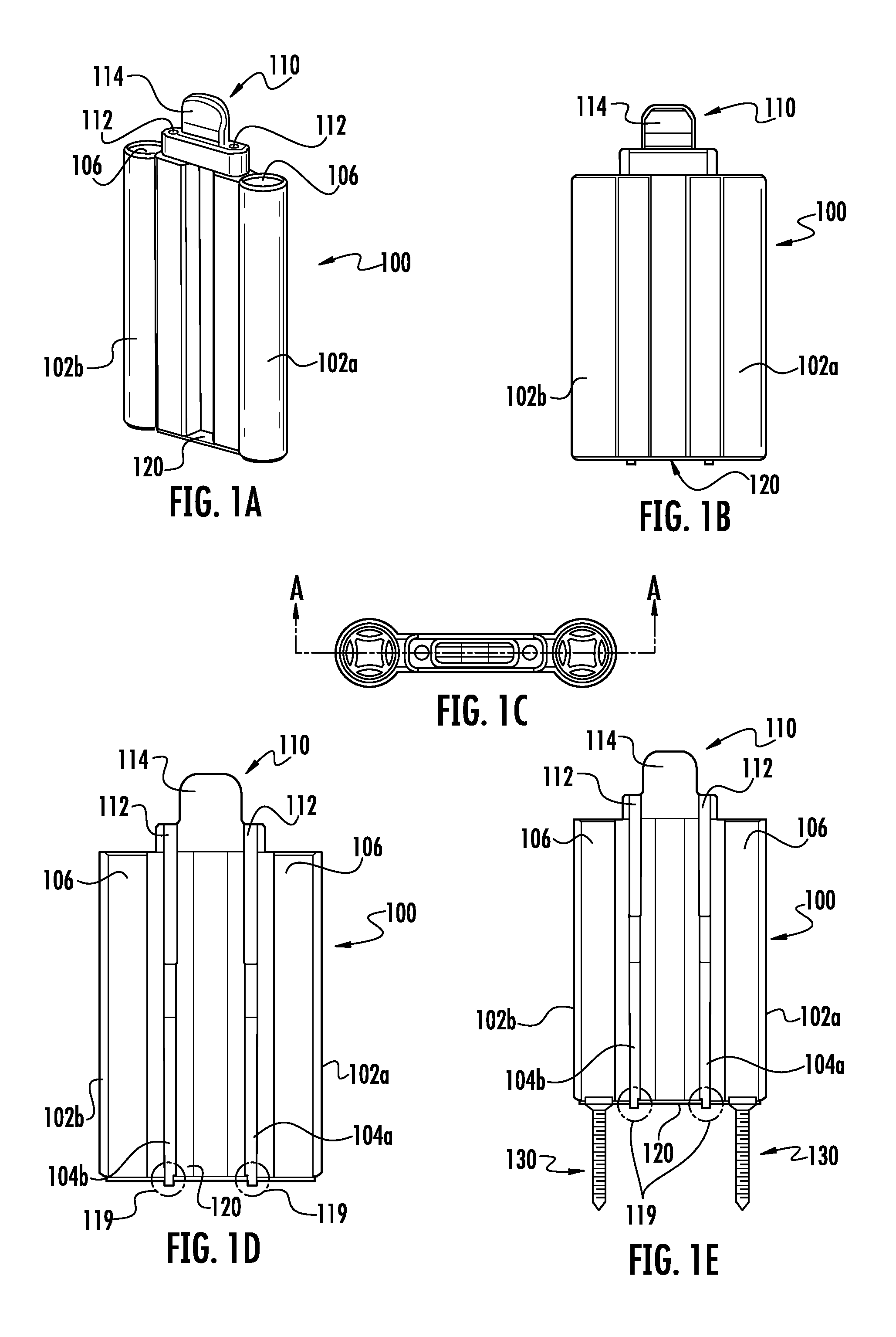
FIG. 1a is a perspective view of a first embodiment of the current invention depicting a multiple component inserter attached to a modular implant or fixation device.
FIG. 1b is a frontal view of the first embodiment shown in FIG. 1a.
FIG. 1c is a top view of the first embodiment showing a section line A-A.
FIG. 1d is the section view A-A shown is FIG. 1c
FIG. 1e is the section view A-A but with bone screws inserted as a means of fixating the implant to the bone.
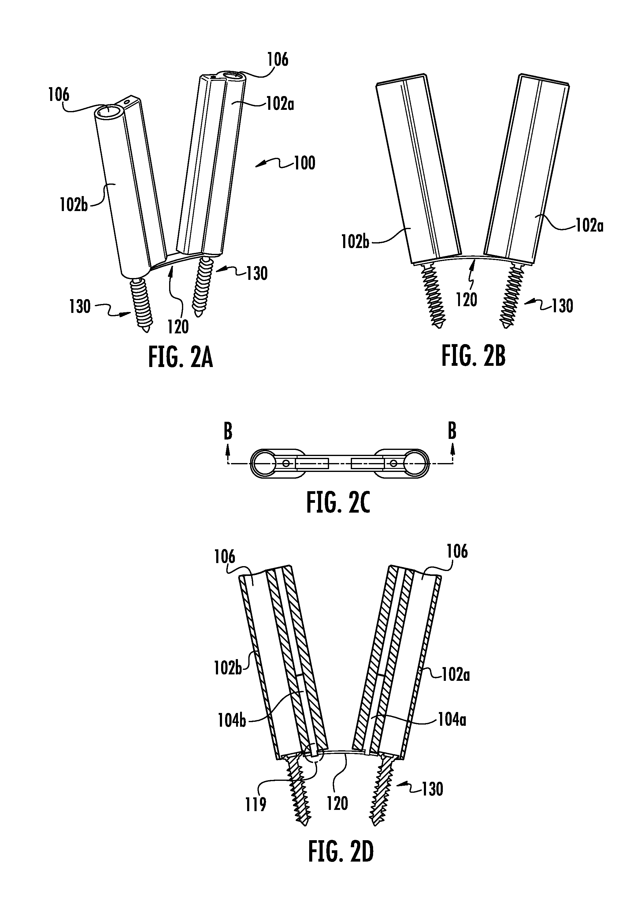
FIG. 2a is a perspective view of the first embodiment of the current invention. depicting a multiple component inserter attached to a modular implant or fixation device.
FIG. 2b is a cross a front view of the first embodiment shown in FIG. 2a.
FIG. 2c is a top view of FIG. 2b showing a section line B-B.
FIG. 2d is the section view B-B shown in FIG. 2c.
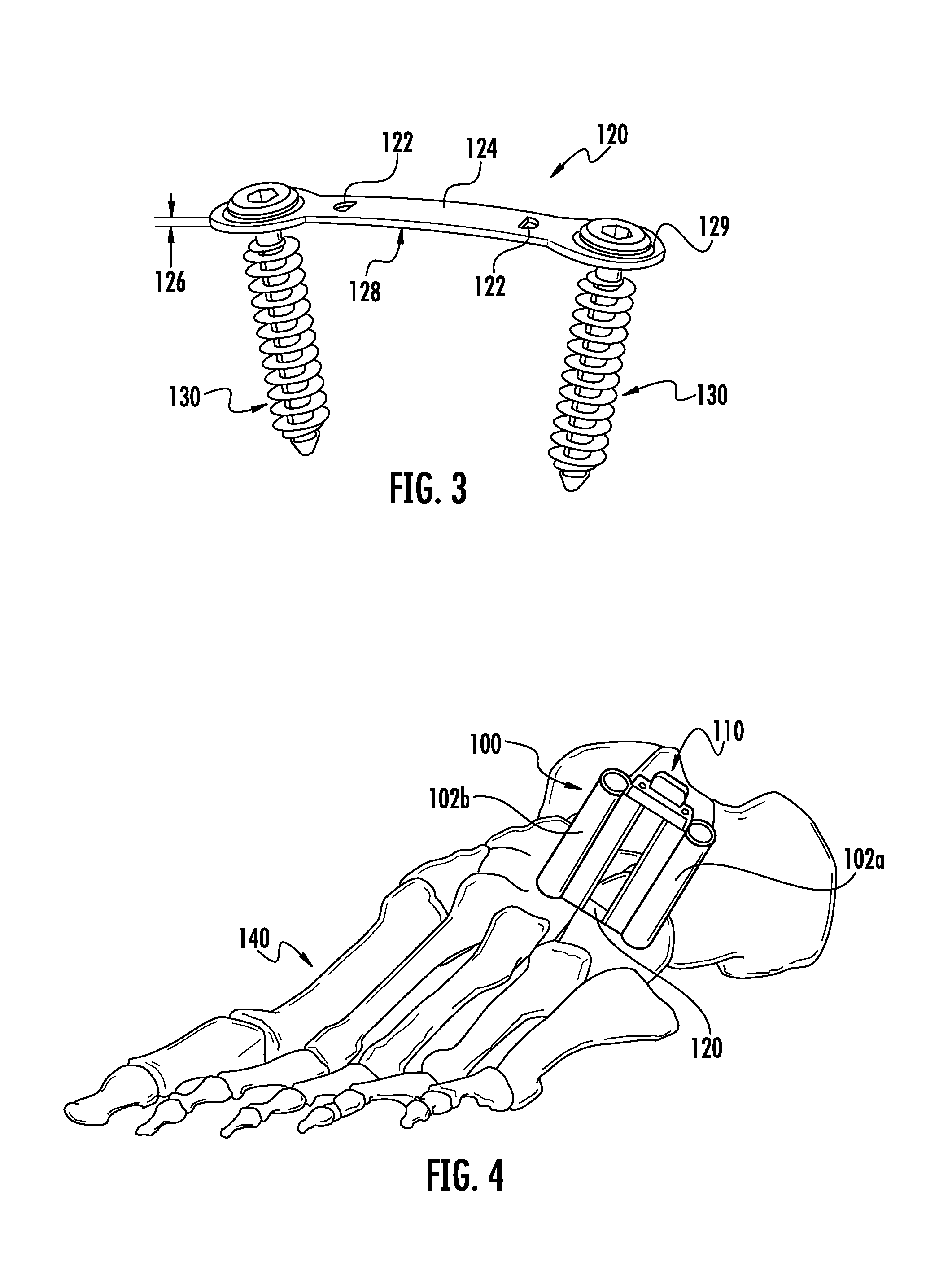
FIG. 3 is a perspective view of the implant of the first embodiment in a second configuration with bone screws assembled.
FIG. 4 is a perspective view of the first embodiment of FIG. 1 on a bone.
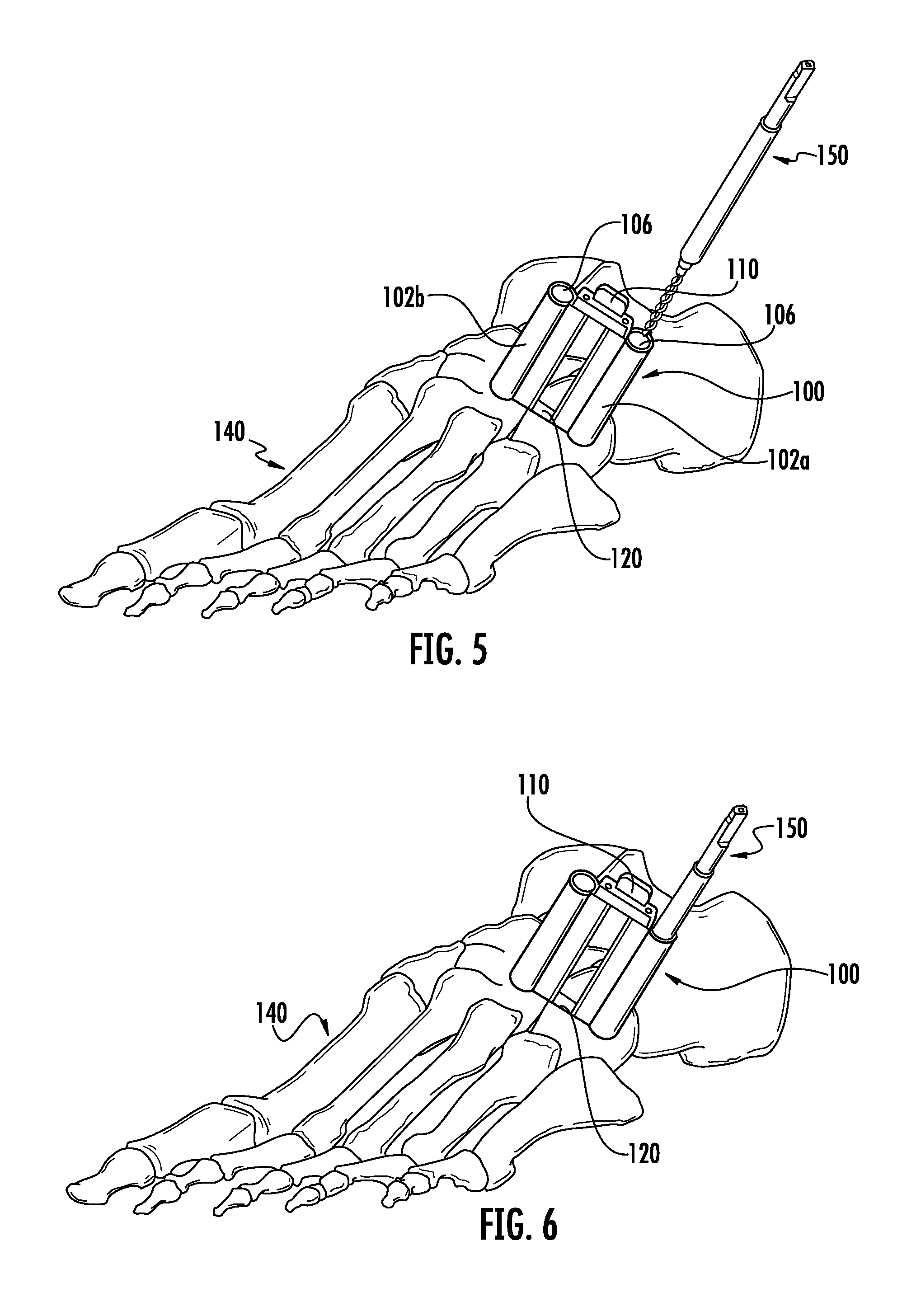
FIG. 5 is a perspective view of the first embodiment of FIG. 1 on a bone and showing preparation of the bone with a drill bit.
FIG. 6 is a perspective view of the first embodiment of FIG. 1 on a bone and showing preparation of the bone with a drill bit.
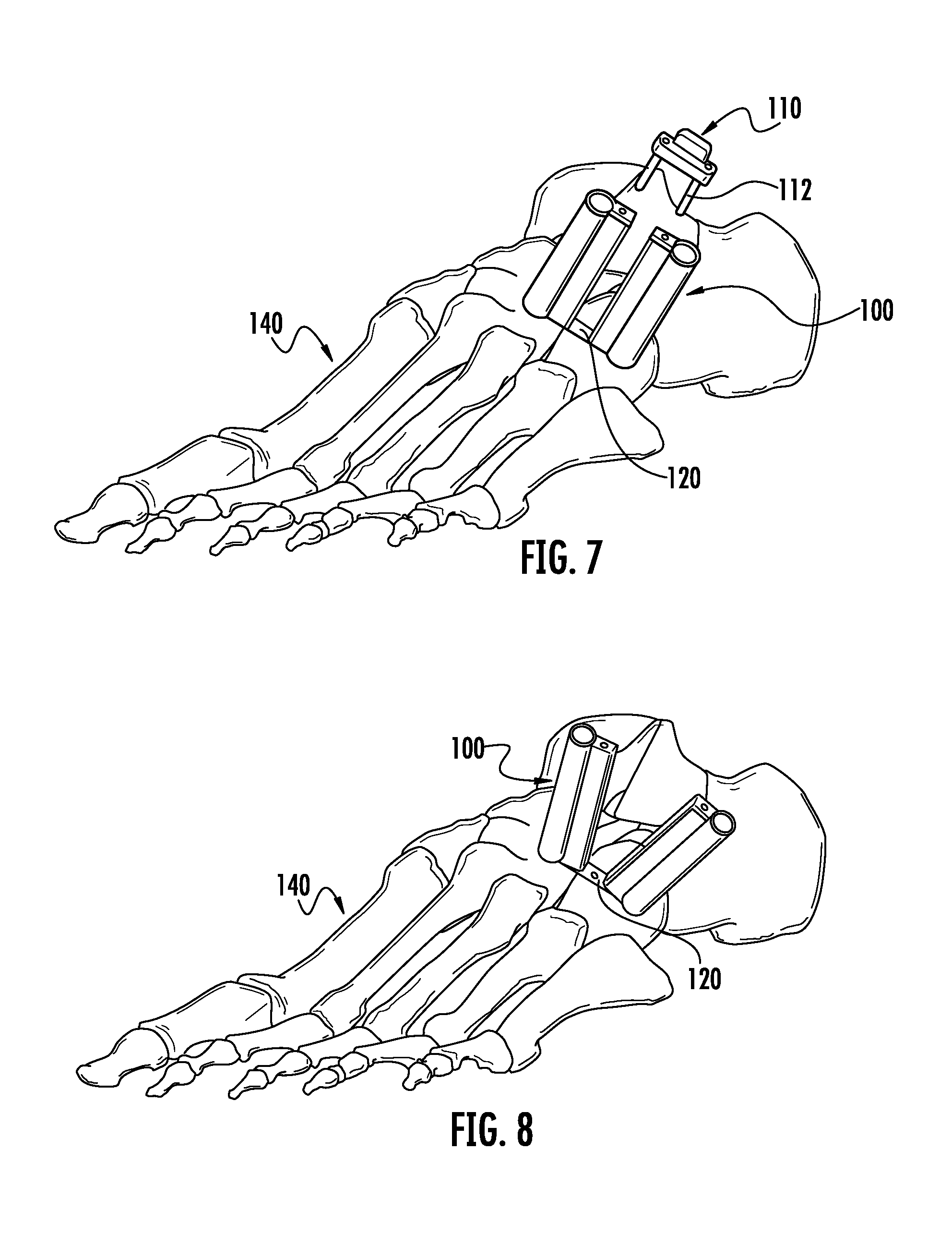
FIG. 7 is a perspective view of the first embodiment of FIG. 1 on a bone after the final placement of the implant has been completed.
FIG. 8 is a perspective view of the first embodiment of FIG. 1 on a bone after the final placement of the implant has been completed.
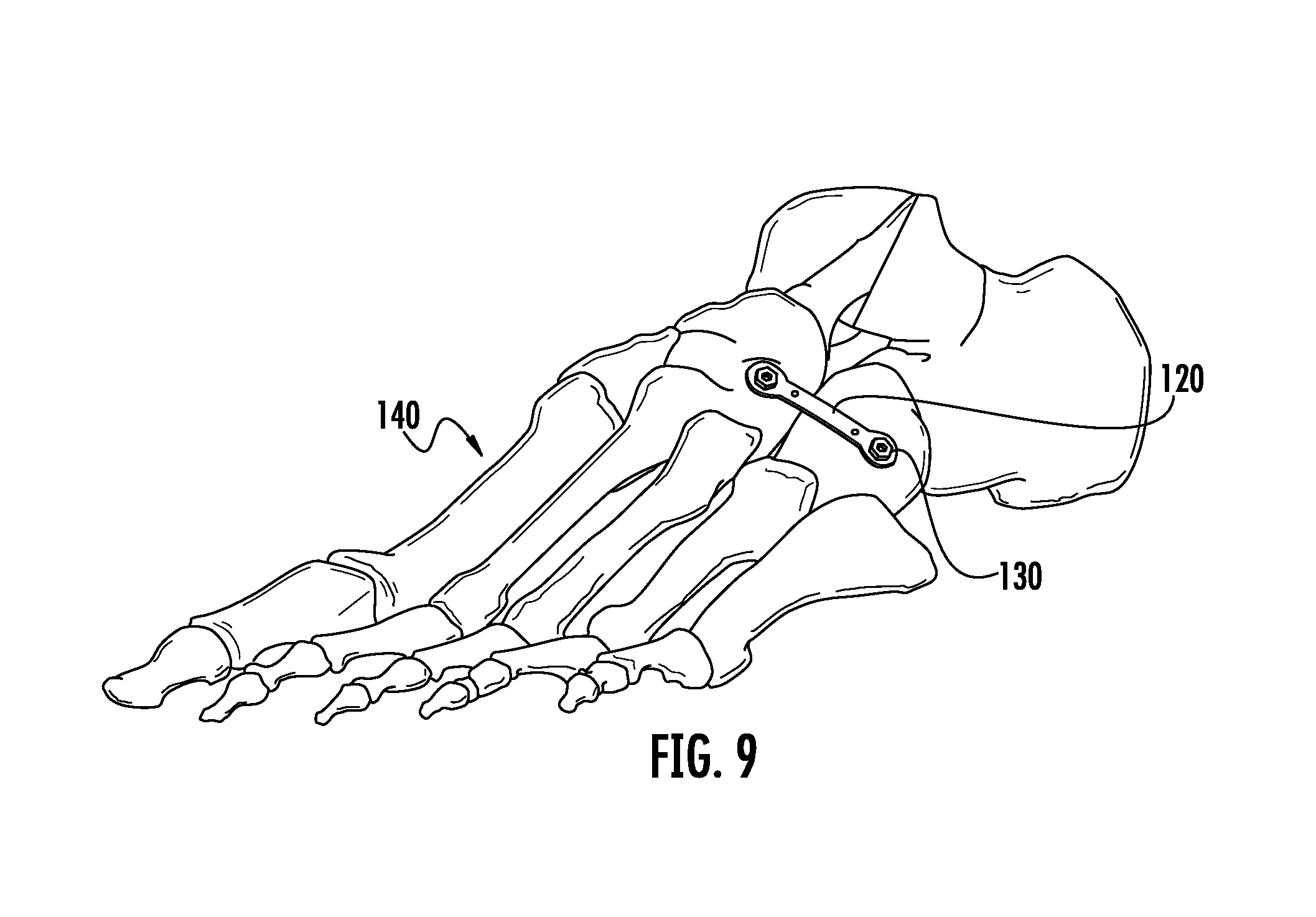
FIG. 9 is a perspective view of the implant of the first embodiment of FIG. 1 on the bone after the final placement of the implant has been completed.
FIG. 10a is a perspective view of the first embodiment of FIG. 1 not shown on a bone showing the use of a drill.
FIG. 10b is a perspective view of the first embodiment showing the drill abutted against the drill guide.
FIG. 10c is a front view of the first embodiment of FIG. 1 not shown on a bone showing a drill abutted against the drill guide.
FIG. 11 is a perspective view of second embodiment of an implant or fixation device shown in a first configuration with parallel leg members.
FIG. 12 is a perspective view of the second implant embodiment of FIG. 11 shown in a second configuration with the legs converging.
FIG. 13 is a perspective view of a second embodiment of an inserter.
FIG. 14 is a perspective view of a second embodiment of an implant or fixation device shown in a first configuration with parallel leg members on the inserter of FIG. 13.
FIG. 15a is a front view of a third embodiment of an implant or fixation device in a first configuration.
FIG. 15b is a front view of the third implant embodiment in FIG. 15a in a second configuration.
FIG. 16a is a perspective view of the third implant embodiment in FIG. 15a.
FIG. 16b is a perspective view of the third implant embodiment in FIG. 15b.
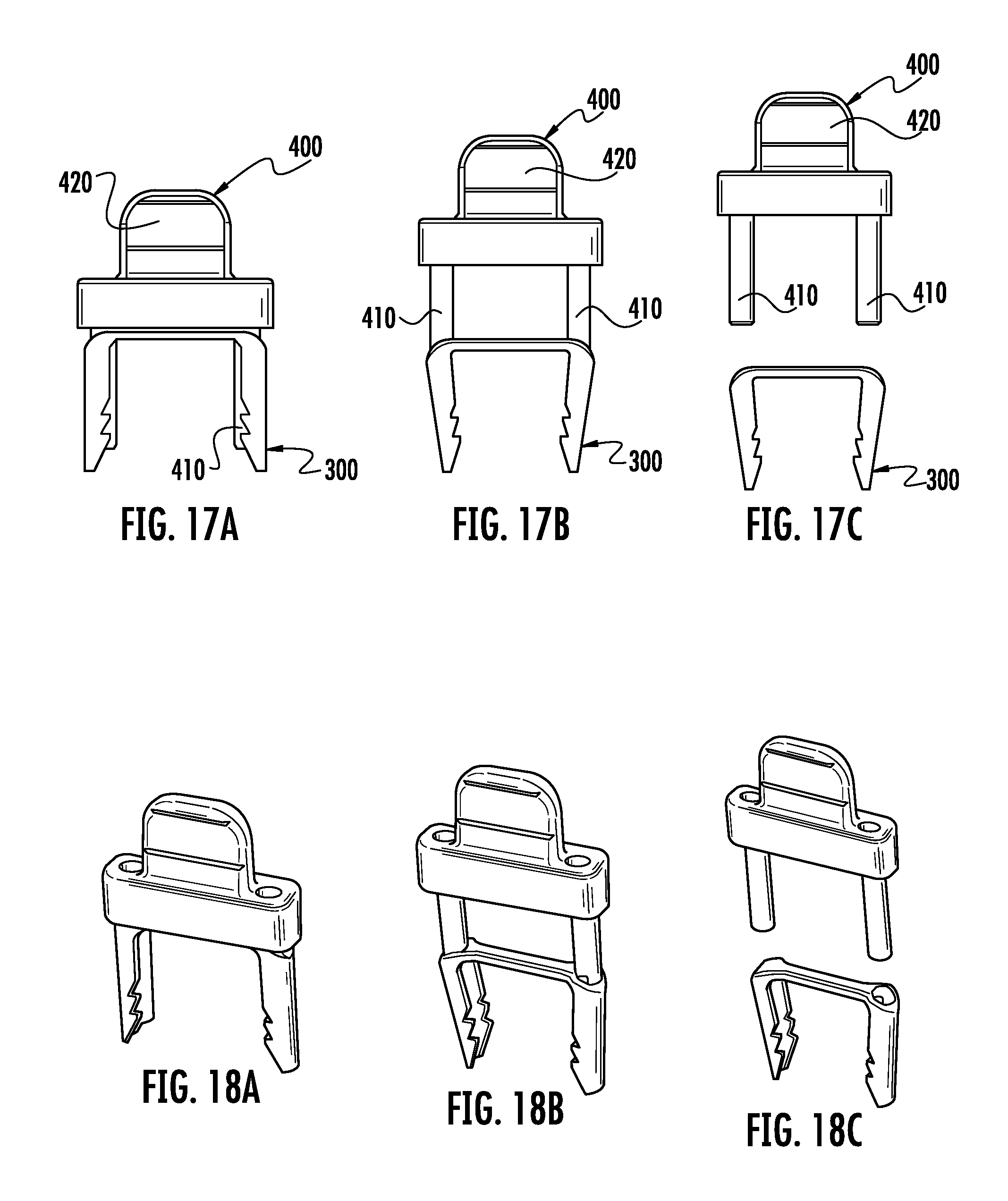
FIG. 17a is a front view of the third embodiment of an implant assembled to the third embodiment of the inserter.
FIG. 17b is a front view of the third embodiment of the implant at the end of engagement to the third embodiment of the inserter.
FIG. 17c is a front view of the third embodiment of the implant separated from the third embodiment of the inserter.
FIG. 18a is a perspective view of FIG. 17a.
FIG. 18b is a perspective view of FIG. 17b.
FIG. 18c is a perspective view of FIG. 17c.
FIG. 19 is a perspective view of a fourth embodiment of the current invention depicting an implant preassembled to an inserter with retractable engagement pins.
FIG. 20 is a close up view of the working tip of the fourth embodiment depicted in FIG. 19.
FIG. 21 is a perspective view of a fifth embodiment of an implant in an alternate configuration with the legs or fixation members out of plane relative to each other.
FIG. 22 is another perspective view of the implant in FIG. 21 showing an alternate configuration with the legs or fixation members out of plane relative to each other.
FIG. 23a is a front view of an implant of a sixth embodiment assembled to an implant carrier.
FIG. 23b is a side view of the implant and implant carrier of FIG. 23a.
FIG. 24 is an isometric view of the sixth embodiment of the implant and implant carrier assembly shown in FIGS. 23a and 23b.
FIG. 25 is a front view of the implant carrier of the sixth embodiment shown in FIG. 24 without the implant assembled to it.
FIG. 26a is an isometric view showing the inserter and an implant/carrier assembly of the sixth embodiment prior to installing the carrier to the inserter.
FIG. 26b is an isometric view of the sixth embodiment shown in FIG. 26a further showing the implant/carrier assembled to the inserter.
FIG. 27a is an isometric view showing the sixth embodiment of FIG. 26 prior to releasing the implant from the inserter and carrier.
FIG. 27b is an isometric view showing the sixth embodiment of FIG. 26 after releasing the implant from the carrier, further showing the implant released from the carrier and the carrier still engaged with the inserter.
FIG. 28 shows the sixth embodiment further depicting the implant, assembled to the inserter via the carrier, being fully seated on the bone, further showing that the inserter and carrier do not interfere with the placement of the implant in its final position.
FIG. 29 is a close-up view of the implant/inserter interface of a seventh embodiment depicting an implant assembled to the inserter further showing the inserter engaging the periphery of the implant thereby not interfering with the final seating of the implant.
FIG. 30 shows the seventh embodiment of FIG. 29 depicting the inserter being released from the implant by rotating the inserter off the implant.
FIG. 31 shows an eighth embodiment of the current invention with engaging members extending through an implant for provisional fixation on the bone surface.
FIG. 32 is a bottom view of an implant of the ninth embodiment of the current invention depicting an implant with a means for connection to bone engaging features and a means for engaging an inserter.
FIG. 33 is a bottom perspective view of the embodiment shown in FIG. 32.
FIG. 34 is a perspective view of the ninth embodiment depicting the implant depicted in FIG. 32 assembled to an inserter of the current invention. The implant is held in a first configuration.
FIG. 35 is a perspective view of the ninth embodiment depicting of the implant depicted in FIG. 32 assembled to an inserter of the current invention. The implant is shown in a second configuration.
FIG. 36 is a bottom perspective view of the implant-inserter assembly depicted in FIG. 34
FIG. 37A is a section view of the implant-inserter assembly depicted in FIG. 34
FIG. 37B depicts alternate geometries for various means of insertion.
FIG. 38 is a top view an of an implant of a tenth embodiment of the current invention depicting a "T" shaped implant with a means for connection to bone engaging features and various means for engaging an inserter.
FIG. 39 is a perspective view of the implant of the tenth embodiment of the current invention.
FIG. 40 is a bottom perspective view of an inserter of the tenth embodiment of the current invention depicting an inserter with means for engaging the implant depicted in FIG. 38.
FIG. 41 is a top perspective view of an inserter of the tenth embodiment of the current invention depicting an inserter with means for engaging the implant depicted in FIG. 38.
FIG. 42 is a top perspective view of a tenth embodiment of the current invention depicting a partial implant-inserter assembly of the implant depicted in FIG. 38 and the inserter depicted in FIG. 40. The implant is shown in a first configuration.
FIG. 43 is a top perspective view of a tenth embodiment of the current invention depicting a completed implant-inserter assembly of the implant depicted in FIG. 38 and the inserter depicted in FIG. 40. The implant is shown in a first configuration.
FIG. 44 is a top perspective view of the tenth embodiment depicting the implant-inserter combination depicted in FIG. 43 depicting a partial disassembly of the implant-inserter combination. The implant is shown in a second configuration.
FIG. 45 is a perspective view of one of the implant-inserter connection means of the assembly shown in FIG. 43.
FIG. 46 is a perspective view of one of the implant-inserter connection means of the assembly shown in FIG. 43.
FIG. 47 is a side view of an eleventh embodiment of the current invention depicting an implant with a means for engaging an inserter.
FIG. 48 is a perspective view of the embodiment depicted in FIG. 47 illustrating the means for engaging an inserter
FIG. 49 is a top perspective view of an eleventh embodiment of the current invention depicting an inserter with means for engaging an implant of the current invention.
FIG. 50 is a top view of the inserter depicted in FIG. 49
FIG. 51 is a front view of the inserter depicted in FIG. 49
FIG. 52 is a bottom view of the inserter depicted in FIG. 49
FIG. 53 is a top perspective view of the eleventh embodiment of the current invention depicting a partial implant-inserter assembly of an implant and the inserter depicted in FIG. 49. The implant is shown in a first configuration.
FIG. 54 is a bottom perspective view of the implant-inserter combination depicted in FIG. 53
FIG. 55 is a top perspective view of an additional embodiment of the current invention depicting a completed implant-inserter assembly of an implant and the inserter depicted in FIG. 49. The implant is shown in a first configuration.
FIG. 56 is a bottom a perspective view the implant-inserter combination depicted in FIG. 55.
FIG. 57 is a perspective view of the eleventh embodiment depicting the implant-inserter connection means of the assembly shown in FIG. 55. The implant is shown in a first configuration.
FIG. 58 is a top perspective view of the eleventh embodiment depicting the implant-inserter combination depicted in FIG. 55 depicting a partial disassembly of the implant-inserter assembly of an implant and the inserter depicted in FIG. 49. The implant is shown in a second configuration.
FIG. 59 is a front view of partial disassembly of the implant-inserter assembly represented in FIG. 58. The implant is shown in a second configuration.
FIG. 60 is a top view of a twelfth embodiment of the current invention depicting an implant with a means for connection to bone engaging features and various means for engaging an inserter.
FIG. 61 is a perspective view of the embodiment shown in FIG. 60.
FIG. 62 is a top view of a thirteenth embodiment of the current invention depicting an implant with a means for connection to bone engaging features and a means for engaging an inserter.
FIG. 63 is a front view of the embodiment shown in FIG. 62
FIG. 64 is a perspective view of the embodiment depicted in FIG. 62 illustrating the means for connection to bone engaging features and the means for engaging an inserter
FIG. 65 is a top view of a fourteenth embodiment of the current invention depicting an implant with a means for connection to bone engaging features and a means for engaging an inserter.
FIG. 66 is a bottom view of the embodiment shown in FIG. 65.
FIG. 67 is a perspective view of the embodiment shown in FIG. 65.
FIG. 68 is a section view of the embodiment shown in FIG. 65.
FIG. 69 is a top view of a fifteenth embodiment of the current invention depicting an implant with a means for connection to bone engaging features and a means for engaging an inserter.
FIG. 70 is a perspective view of the embodiment shown in FIG. 69.
FIG. 71 is a section view of the embodiment shown in FIG. 69.
FIG. 72 is a top view of a sixteenth embodiment of the current invention depicting an implant with a means for connection to bone engaging features and a means for engaging an inserter.
FIG. 73 is a front view of the embodiment shown in FIG. 72.
FIG. 74 is a bottom view of the embodiment shown in FIG. 72.
FIG. 75 is a perspective view of the embodiment shown in FIG. 72.
FIG. 76 is a perspective view of a seventeenth embodiment of the current invention depicting an implant with a means for connection to bone engaging features and a means for engaging an inserter.
FIG. 77 is a side view of the implant depicted in FIG. 76.
FIG. 78 is a front view of an eighteenth of the current invention depicting an implant with bone engaging features and a means for engaging an inserter.
FIG. 79 is a perspective view of the embodiment depicted in FIG. 78
DETAILED DESCRIPTION OF THE INVENTION
The present invention may include a fastening device and an inserter. Exemplary embodiments of the fastening device and inserter are shown in FIGS. 1, 14 and 19. The fastening device may be of a configuration similar to a modular staple or bone plate as shown in FIG. 3. The fastening device may also have a configuration resembling a bone staple as shown in FIGS. 11, 12, 15 and 16. The present invention may have the inserter pre-assembled or affixed to the implant as shown in FIGS. 1 and 14. The implant or implants may not be pre-assembled to the inserter. The implant or implants could be held in a particular configuration in the packaging that facilitates engagement with the inserter. FIGS. 11 and 12 depict an embodiment of the fastening device or implant that shows one possible combination of implant configurations. FIGS. 11 and 14 show this embodiment maintained in a first configuration for insertion. FIG. 12 shows this embodiment in its free-state or implanted-state configuration.
The embodiments described herein may be used in connection with any type of inserter or fixation device, including but not limited to various bone staples, bone plates, etc. that have more than one implant configuration where the insertion device does not interfere with the final placement of the implant.
As shown in FIGS. 1a, 1b, 1d and 1 e, the inserter 100 is assembled to the implant 120. The implant 120 is shown in a first configuration that may or may be flat. The inserter 100 may or may not have features that allow preparation of the bone for receiving other members of the implant. In this embodiment, the inserter 100 has two tube members 102a and 102b that allow the bone to be prepared through the internal diameters 106. The tube members 102a and 102b also serve as drill guides. Implant 120 is temporarily connected to the tubes 102a and 102b by the engagement pins 104a and 104b. The two independent tubes 102a and 102b are individually connected to the implant 120 by the engagement pins 104a and 104b. The engagement pins may or may not extend completely through the implant. The engagement pins could also be temporarily or permanently attached to the implant as opposed to being part of the inserter assembly. The engagement pins may extend through the implant with features that engage the bone for provisional fixation during the procedure. Also, this embodiment shows the use of circular pins, however, to those skilled in the art the use of other attachment means will be obvious and may or may not be separate pieces from the tube members. The means of attaching the plate to the inserter is shown on the bridge area of the plate, but could occur anywhere on or around the periphery of the plate. The two independent tubes are held in relative position to each other by clip 110. Clip 110 has a means for holding during insertion or removal, tab member 114, and two engagement pins 112. The engagement pins 112 engage the tubes 102a and 102b to hold them in relative position to each other thereby maintaining the implant 120 in its first configuration. FIG. 1e depicts the inserter with the bone screws 130 inserted into the implant 120 while the implant is maintained in its first configuration. FIGS. 1c and 1d show an engagement 119 where the engagement pins 104a and 104b controllably interface with the engagement holes 122 shown in FIG. 3. Implant 120 is shown in a first configuration in FIGS. 1a, 1b, 1d and 1 e. Alternatively, the inserter 100 may be used for implant manipulation or for holding the implant in a first configuration with or without a means for preparing for other implant members, e.g. bone screws. The bone preparation may or may not be distinct from the inserter. Bone preparation may be done in the implant first configuration and/or in a second configuration.
FIGS. 2a, 2b, 2c and 2d depict the inserter 100 without the clip 110. The inserter assembly 100 is shown in a manner depicting an initial release step that may or may not allow the implant 120 to have a second configuration. In this embodiment, the bone screws 130 have been prepared and placed into the implant 120. The inserter tubes 102a and 102b are still engaged in the implant 120 via the engagement pins 104a and 104b. The implant 120 is shown in a second configuration and is achieved either by the intrinsic mechanical properties of the material or secondary mechanical manipulation of one or more areas of the plate. FIGS. 2a, 2b, 2c and 2d show the inserter temporarily attached to the implant after preparation of the bone and placement of the bone screws 130. The inserter 100 is shown just prior to removal of the inserter 100 from the implant 120. The independent inserter tubes 102a and 102b accommodate the second configuration of the implant 120.
FIG. 3 depicts the implant 120 in its second configuration after removal of the inserter 100 or possibly after secondary mechanical manipulation/deformation. The bone screws 130 may be prepared and positioned through the internal diameter 106 while the inserter 100 was still attached to the implant 120. FIG. 3 shows one embodiment of the engagement hole 122 that accepts the engagement pins 104a and 104b of the inserter tube 102a and 102b.
FIG. 4 depicts one embodiment of the inserter 100 assembled to implant 120 on a foot 140. FIGS. 5 and 6 depict one embodiment of the inserter 100 assembled to implant 120 on a foot 140 further showing preparation of the bone 140 with drill 150 through the internal diameter 106 to accept bone screws or other fixation features of the implant 120. In FIGS. 4, 5 and 6, clip 110 maintains the tubes 102a and 102b in a relative position to each other. Clip 110 may or may not be a separate assembly; the functionality could be achieved via an integral feature, molded-in for example, to the tube(s). Clip 110 is shown to provide a rigid, static connection between the tubes 102a and 102b. The connection mechanism between the tubes 102a and 102b may also have a dynamic, moveable connection (e.g. application of springs) so that the tubes will allow the plate to conform in some way to the bone prior to complete removable of clip 110. The tubes 102a and 102b are controllably engaged in implant 120 via engagement pins 104a and 104b and engagement features 122. In this embodiment, the clip 110, the tubes 102a and 102b, engagement pins 104a and 104b and engagement holes 122 act together to maintain the implant 120 in a first configuration. In alternate embodiments more components or fewer may be needed to maintain the implant in a first configuration.
FIG. 7 depicts one embodiment of the inserter 100 assembled to implant 120 on a foot 140. This figure depicts the first removal step for this particular embodiment of the inserter 100. In FIG. 7 the bone has been prepared accordingly and the implant 120 is in its final position on the bone and its first configuration. FIG. 7 shows removal of clip 110 from inserter 100. As further shown in FIG. 8, removal of the clip 110 from the inserter 100 after completing the appropriate bone preparation allows the implant 120 to adapt to a second configuration while the implant 120 is in its final implant position. Bone screws 130 (not shown in FIG. 7 or 8) may or may not have been prepared and positioned while the inserter assembly 100 was engaged to the implant 120. FIG. 9 shows implant 120 on bone 140 after removal of the inserter assembly 100 after the implant 120 is in its final position either before or after the implant achieves its second configuration.
FIG. 10a depicts an exemplary embodiment of the inserter assembly 100 and implant 120 while also showing preparation steps with drill 150 lined up with the internal diameter 106 of the tubes 102a and/or 102b. FIGS. 10a, 10b and 10c further show implant 120 controllably engaged to the tubes 102a and 102b with engagement pins 104a and 104b (pins not shown in image) engaged in engagement holes 122. Clip 110 is controllably maintaining the tubes relative to each other with the engagement pins 112 engaged in the tubes 102a and 102b. Drill 150 has a fluted region 152, a shaft 154 and a stop 156. FIG. 10b and FIG. 10c show the drill stop 156 abutted against the top surface of the drill tube 102a or 102b. The stop 156 may be used to prevent the drill from extending too far into the bone during preparation. The stop 156 may be used to control the drill depth so the fluted region 152 only protrudes through the drill guide/tubes 102a and/or 102b to a predetermined depth.
In this exemplary embodiment the implant 120 may be made of a material that may have elastic or spring properties that allow the implant to have more than one configuration. FIG. 3 shows the implant 120 in a possible free-state or implanted-state of the device. The free-state or implanted-state may provide compression (or distraction) across bone members. FIG. 3 shows the implant 120 having a thickness 126 and a bridge member 124. It further shows the implant 120 having an arc or radius 128 while in its second configuration. FIG. 3 also shows an example of a bone attachment device 130, which in this case resembles a bone screw. The attachment device 130 is rigidly attached to the implant 120 through the attachment feature 129. The attachment feature 129 is such that it allows the bone attachment device to be locked to the material that may have elastic properties. The bridge member 124 depicted in FIG. 3 also has an engagement feature 122 for controllably engaging the inserter for maintaining the first configuration. The embodiment depicted thus far allows the implant 120 to be fully seated to the bone in its final position without the inserter interfering with this final position. When the implant is placed in its final position, it may or may not be in its second configuration. The implant may remain in a first configuration until the inserter is removed or further manipulation is performed.
FIG. 11 shows an exemplary embodiment of an implant 200 that resembles a bone staple. The implant is shown in a first configuration where the legs 220 are relatively parallel to each other. This first configuration may be useful in facilitating implantation of the implant 200 into bone. The first configuration may be the configuration that is maintained by an inserter. FIG. 11 depicts implant 200 having a bridge member 210 with a thickness 202. Thickness 202 may or may not be more or less than thickness 204. This particular embodiment shows the bridge member 210 have a radius 206. Radius 206 may or may not be present. FIG. 11 further shows legs 220 having a feature 230 for engaging an inserter. The engaging feature 230 may be an internal feature, external feature, may be positioned on the interior or exterior of the legs 230. It is also reasonable to have an engagement feature similar to engaging holes 122 in this type of device. Implant 200 has bone engagement means in the form of barbs 225 which engage the bone in order to maintain the implant in the bone. FIG. 12 shows the implant 200 of FIG. 11 in a second configuration. In this particular configuration of FIG. 12, the legs 220 converge towards each other. Either one or multiple legs may move to create this convergence or distraction. The second configuration may be the free-state or implanted-state.
FIG. 13 shows another embodiment of an inserter 240. Inserter 240 has a holding piece 242 and at least one engaging pin 244. The engaging pins 244 are spaced and oriented appropriately to interact with an implant to maintain a first configuration. FIG. 14 shows the inserter 240 assembled to an implant 200. The engaging pins 244 of inserter 240 engage the internal diameter 230 of implant 200 to maintain the implant 200 in a first configuration. When the inserter 240 is removed the implant assumes a second configuration as shown in FIG. 12.
FIG. 15a shows yet another embodiment of an implant or fixation device 300. The implant 300 has a bridge member 310 and leg members 325. The bridge member 310 has a thickness 315 that may or may not be the same as the leg thickness 320. FIG. 15a shows the implant in a first configuration. FIG. 15b shows the implant 300 in a second configuration. The implant of FIGS. 15a and 15b is also shown in FIGS. 16a and 16b depicting an internal diameter 330. Opening 340 is generated by the internal diameter 330 breaking out into the inside of the leg. The opening 340 may or may not be needed for this current invention. The internal diameter 330 may be used to engage the inserter and maintain the implant in a particular configuration. The internal diameter 330 may also be used to manipulate the implant into another configuration whereas the relationship between the implant legs 325 is changed by creating convergence, divergence or some other out of plane relationship.
Alternate embodiments may include an inserter and implant that work in conjunction to create a first and second configuration.
FIG. 17a shows an embodiment of an implant 300 on an inserter 400 with the implant being in a first configuration. FIG. 17b shows the same embodiment with the implant 300 at the end of the engagement pins 410 of the inserter 400. The implant in FIG. 17b is transitioning to a second configuration. FIG. 17c shows the implant 300 fully disengaged from the inserter 400. The implant 300 is in a second configuration. FIGS. 18a, 18b and 18c depict the embodiments in FIGS. 17a, 17b and 17c in a perspective view.
The embodiments shown herein depict the engagement between the implant and inserter as using pins. Those skilled in the art will appreciate that various means may be used to attach the implant to the inserter.
FIGS. 19 and 20 depict an embodiment of an inserter 500 that is preassembled to an implant 300. The inserter 500 has a holding means 510 and an impact or seating means 530. Handle 520 is slide-ably engaged in the body 505. The assembly 500 has means for engaging an implant, 515. In this embodiment the engaging means are pins 515. Pins 515 are connected to handle 520 such that the pins will retract from implant 300 thereby ejecting or releasing the implant from the inserter assembly 500. In this embodiment the pins or engagement means are retractable. Those skilled in the art will appreciate that the same effect can be achieved without retractable engagement means where the implant may be pushed off the engagement means with a plunger type mechanism that may push the implant off or from the inserter assembly.
FIGS. 21 and 22 show an embodiment of an implant in an alternate configuration. This embodiment resembles a bone staple, but those skilled in the art will appreciated that this embodiment could also be achieved with modular fixation means such as bone screws. The implant 600 has a bridge member 610 with thickness 615. The bridge member 610 is connected to fixation members or legs 620. Legs 620 are out of plane relative to each other. Legs 620 may or may not be out of plane relative to the bridge member 610. The implant 600 may have engaging features 630 to control and/or manipulate the implant into alternate configurations. The engaging features 630 may or may not extend through the entire implant. The engaging features 630 may be positive or negative features in the implant or inserter. This alternate configuration may or may not be achieved through the inherent material properties of the implant material. The implant may achieve this alternate configuration by transitioning from, for example, configuration 1 to configuration 2 to configuration 3. Where configuration 1 may be that as attached to the inserter or delivery instrument and configuration 2 may be a configuration where the leg members 620 are in a compressed state and where configuration 3 may be a configuration where the compressed legs of configuration 2 are made to be out of plane to each other. Alternately, the implant may achieve this alternate configuration by transitioning from, for example, configuration 1 to configuration 2. Where configuration 1 may be that as attached to the inserter or delivery instrument and configuration 2 may be a configuration where the leg members 620 are in a compressed state and are made to be out of plane to each other. This embodiment is not intended to be limiting. The transition from one configuration to another configuration may be one distinct transition or more than one distinct transition. The transition may be due to the inherent material properties or achieved by a manipulation of the material or a combination thereof.
The embodiments described herein can be manufactured from a number of different materials or combinations of materials. Nitinol, for example, possess material properties, such as shape memory and/or super elasticity that may provide the inherent properties to allow an embodiment to have multiple configurations with or without an external mechanical manipulation. Stainless steel and/or titanium also have desirable material properties for the embodiments described herein. Stainless steel and/or titanium may not possess shape memory or super elasticity, but may possess the mechanical properties for embodiments that may benefit from mechanical manipulation to achieve multiple configurations. Still other materials such as PEEK or other polymers may also possess material properties beneficial for the embodiment described herein. A combination of materials may also be preferred. For example, a nitinol plate with titanium screws may be the materials of choice for some embodiments. Those skilled in the art are aware of the typical materials and combinations of materials applicable to the current invention.
Yet another embodiment of this invention may have the implant assembled onto a holding means such as an apparatus or carrier that may be assembled to an inserter at the time of surgery, as shown in FIGS. 23a, 23b, 24, and 25-28.
FIGS. 23a and 23b show an exemplary embodiment of an implant carrier, 700, assembled to an implant embodiment, 800. FIG. 23a is a front view of the assembly and FIG. 23b is a side view of the assembly. FIG. 24 shows the carrier, 700, slidably engaged to the implant, 800. Implant 800 has features 810 for receiving the engaging features 710 of the carrier. The carrier 700 may have features and/or geometries 720 for engaging the inserter. The carrier 700 may have features and/or geometries 730 for additionally engaging the inserter. The engaging features and or geometries 720 and 730 may be used separately or in combination to provide a poka-yoke feature that prevents incorrect assembly of the carrier to the inserter. Features 720 and or 730 may also be used to assist the inserter in removing the carrier from the implant, i.e. releasing the implant from the carrier, at the time of implantation. The carrier 700 may be configured to fit multiple sized implants. The engaging features 710 of the carrier 700 may change from size to size in order to optimize the fit between the implant 800 and carrier 700. The engaging features (e.g. 720 and 730) of the carrier may or may not change by implant size. Keeping such features consistent among varying implant sizes may allow the use of multiple implant carriers with the same inserter.
FIG. 25 more clearly shows the carrier 700 without an implant assembled. As previously described the carrier 700 has features 710 for slidably or by other means attaching and securing the implant in position on the carrier. The inserter engaging feature 720 may have multiple configurations or geometries. The engaging feature 720 may provide an engagement with the inserter that allows the inserter to retract the carrier from the implant 800. Engaging feature 730 may also be used to attach to the inserter and may provide a poka-yoke feature to prevent improper assembly of the carrier 700 to an inserter. To those skilled in the art, it will be apparent that the function of features 720 and 730 may be combined or alternated to achieve the same purpose and function described in this embodiment.
FIG. 26a and FIG. 26b show an exemplary embodiment of an inserter 900 and the implant 800 assembled to the carrier 700. FIG. 26a shows the inserter 900 with the implant carrier 700 prior to assembling the carrier 700 to the inserter 900. FIG. 26b shows the carrier 700 with the attached implant 800 assembled to the inserter 900. In this exemplary embodiment the inserter 900 has a base component 910, a handle component 920 and a locking means 930. The inserter also may have a retaining member 940 that may be used for assisting in maintaining the carrier 700 in a specified position. Retaining member 940 may or may not be integrated into the handle component 920. This inserter embodiment has features 950 for engaging with the carrier 700 in a poka-yoke means. The locking means 930 may be used to secure the handle component 920 to the base component 910.
FIG. 27a and FIG. 27b show the exemplary embodiments of FIG. 26a and FIG. 26b in an upright isometric view. FIG. 27a shows the carrier 700 and implant 800 attached to the inserter 900 prior to releasing the implant 800 from its carrier 700. FIG. 27b demonstrates one embodiment for releasing the implant 800 from the carrier 700. FIG. 27b shows the handle 920 in a retracted position that removes the carrier 700 from the implant 800. In the state shown in FIG. 27b the implant is now free from the carrier 700. The carrier 700 may be removed from the inserter 900 and replaced with another implant/carrier assembly.
FIG. 28 demonstrates the exemplary embodiments of the inserter 900 the carrier 700 and the implant 800 allowing the implant 800 to be seated flush against a bone surface 1000. One will notice that the inserter 900 does not interfere with the final placement of the implant 800. For an implant 800 having a second configuration where the parallel legs are allowed to converge after releasing from the inserter 900 and carrier 700, not having to perform a secondary final seating of the implant after release from an inserting device is beneficial.
FIG. 29 shows a close-up view of the implant/inserter interface of another exemplary embodiment of an inserter 1100 and an implant 1200. The inserter 1100 has means 1120, 1130 and 1110 for attaching to the implant. These attachment means engage the implant 1200 in such a way to not prohibit final seating of the implant 1200 in its final desired position. FIG. 30 shows one possible means for releasing the implant 1200 from the inserter 1100. This embodiment demonstrates a rotation of the inserter 1100 relative to the implant 1200. This rotation releasing the engaging means 1120 and 1130 while rotating about the pin 1110. Once fully rotated and released the inserter 1100 can be removed from implant 1200.
FIG. 31 shows the previously described inserter embodiment 100 and 110 assembled to implant 120. It further shows an embodiment of the engaging means 190 that may purposely extend beyond the implant 120. The engaging means 190 shown may have tips that are configured to penetrate into a bone surface to provide provisional fixation.
FIG. 32 depicts an embodiment of the implant 1600 which includes multiple connection means (means for fixation to a bone) 1620 for receiving bone engaging members. The bone engaging members may be bone screws, pegs, blades or other means suitable for engaging bone or soft tissue. The connection means 1620 may be of the same or varying styles or geometries for a particular implant. For example, some of the connection means 1620 in implant 1600 may be threaded and or locking while others may be non-threaded or non-locking. Implant 1600 has a bridge area 1601 spanning between the connection means 1620. The bridge area 1601 may or may not have multiple rails or members 1602. This particular embodiment depicts two rail members 1602 defining a space 1603 with a perimeter 1645. As further shown in FIG. 33 the space 1603 has a lower surface 1641 and 1642 that is recessed from the bottom surface 1640. Lower surfaces 1641 and 1642 may be of similar or different configurations and or geometries suitable for engaging a means of insertion. FIG. 34 depicts an inserter 1650 that is engaged with the implant 1600. Inserter 1650 has two members 1652 and 1651 with a space 1655 therein. FIG. 34 shows the implant 1600 held in a first configuration which may or may not be flat. This first configuration may facilitate the surgical implantation. This first configuration may act to store a compressive force or other force. FIG. 35 shows the inserter 1650 partially disengaged from implant 1600. The members 1651 and 1652 may come together thereby reducing the space 1655 that may enable or facilitate assembly and or disassembly of the inserter 1650 and implant 1600. As depicted in FIG. 35 as the inserter 1650 is disengaged from the implant 1600 the implant is allowed to take on a second configuration. This second configuration may be achieved by the design of the implant 1600 and or in combination with the intrinsic material properties of the implant and or in combination with the processing of the implant 1600. This second configuration may act to create a compressive force or other force across one or two bone or tissue segments.
FIG. 36 depicts the implant 1600 releasably attached to the inserter 1650. The implant engaging means 1660 and 1661 of the inserter 1650 may engage the implant 1600 by interfacing the implant surface 1641 and 1642. The arms of the inserter 1651 and 1652 may pass through space 1603 to engage the implant 1600.
FIG. 37A depicts a possible cross section of the implant-inserter combination. The implant is shown in a first configuration. The arms 1651 and 1652 of the inserter 1650 may pass through space 1603 of the implant thereby allowing the upper surfaces 1671 of the engaging members 1660 and 1661 to interface with the lower surfaces 1641 of implant 1600. Once engaged the inserter arms 1651 and 1652 may provide a force that maintains the implant in a first configuration. In this exemplary embodiment the inserter 1650 is depicted passing through an internal space 1603 of implant 1600. In other embodiments the inserter may engage on an external feature as will be demonstrated herein. In the current embodiment, the general shape of the engagement is depicted as an "L" shape interface. However to those skilled in the art it is apparent that numerous geometries and configuration or combination of geometries and configurations that are possible and may be encompassed by the current invention. FIG. 37B depicts several possible alternative geometries for connection to a means of insertion that may be used to maintain a particular implant configuration. FIG. 37B depicts geometry 1690 which may be generally "L" shaped. FIG. 37B depicts geometry 1691 which may be generally angled faces or tapered faces or chamfered edges. FIG. 37B depicts geometry 1692 which may be generally a threaded or other fastening geometry. FIG. 37B depicts geometry 1693 which may generally represent a bending modality that may utilize specific geometries in combination with locations on an implant surface to maintain a particular implant configuration. FIG. 37B depicts geometry 1694 which generally may be a combination of a square geometry and a "L" shaped geometry. The means of insertion may or may not be flush with the implant. A combination of features may be used to maintain an implant in a particular configuration or combination of configurations. Certain combinations may be used to hold certain implant features in a configuration that may or may not be the same as the entire implant. For example, certain features or combinations of features may be used to hold one arm or projection of an implant in an upward direction while another feature or combination of features may be used to hold a different arm or projection or portion of an implant in a downward direction. This may allow certain aspects of an implant to achieve various configurations. The connection between an implant and inserter and the means of insertion my hold the implant in a first configuration and or an alternate configuration. As the inserter and implant are disassembled, the disassembly may allow the implant to achieve a second or alternative configuration. This disassembly may allow the implant to achieve multiple alternative configurations. For example, step 1 of the disassembly may allow the implant to achieve a second configuration and step 2 may allow the implant to achieve a third configuration and step 4 of the disassembly may allow the implant to achieve a third configuration. This disassembly may allow the implant or portions of the implant to achieve multiple alternative configurations. For example, step 1 of the disassembly may allow the portion A of the implant to achieve a second configuration and step 2 may allow portion B of the implant to achieve an alternate configuration and step 4 of the disassembly may allow portion C of the implant to achieve an alternate configuration. Those skilled in the art will understand that combinations of alternate configurations of an implant or portions of an implant may be possible with the current invention. Certain alternate configurations may be intermediate configurations that will revert to a previous configuration or may proceed to a final configuration once fully disassembled from the inserter. The embodiments described herein do not limit the scope of the current invention. Further embodiments and combinations of embodiment may be possible and will become evident to those skilled in the art. The current invention may include an inserter and inserter-implant combination that may be used with an implant that has one or more configurations.
An implant of the current invention may be assembled to an inserter or other delivery instrument by several means that will be evident to those skilled in the art. The implant may be pre-assembled in the packaging or assembled at the time of use. The implant may be predisposed to a first configuration then assembled to an inserter. The implant may be predisposed by various means to achieve a first configuration for assembly with an inserter. Alternatively, an implant may be predisposed by various means to achieve a pre-assembly configuration for assembly with an inserter whereas the pre-assembly configuration may or may not be equivalent to the first configuration or second configuration. The implant may be predisposed by various means to achieve this alternate configuration for assembly with an inserter or other delivery instrument which may include physical deformation of the implant such as bending or mechanical manipulation, for example applying a force to the implant on flat surface or other surface to temporarily hold the implant in a shape for assembly to the inserter. The implant may be predisposed by various means to achieve this alternate configuration for assembly with an inserter which may include application of an external temperature change, either by heating, cooling and or freezing the implant that may create a change in the physical properties of the material such as to facilitate an alternate configuration for assembly. The implant may be predisposed by various means to achieve this alternate configuration for assembly or re-assembly with an inserter which may include assembly or re-assembly at the time of use. If an implant is already positioned or implanted, either partially or fully, the implant may be in a sufficient configuration that would allow re-assembly of the inserter or other instruments. This may have advantages over existing technologies and may be beneficial in allowing an implant to be removed, repositioned or otherwise adjusted. In addition, the advantages of the current invention may include the ability for the end user to assemble a multi configuration implant to an instrument at the time of use. As shown in the embodiments described herein, the inserter may be designed to provide a means for assembly; a means for maintaining a first implant configuration; and or a means for delivering an implant and achieving an alternate configuration. The instrument may include features such as chamfers, ramps, steps, shoulders, mechanical levers, mechanical interfaces, complementary geometries, etc. for manipulating an implant from an alternate configuration to a first configuration for means of assembly and maintaining a first configuration. The means of assembly may be achieved by a single feature or multiple features on a single inserter or delivery instrument. The means of assembly may be achieved by a single feature or multiple features on a single inserter or delivery instrument or by the use of multiple delivery instruments used sequentially or simultaneously in combination.
FIG. 38 depicts an embodiment of an implant 1900 of the current invention in a "T" shape. Implants may take on many various configurations. The merits of the current invention are not limited by the shape or style of the implant. In FIG. 38 implant 1900 is shown in a first configuration. The implant 1900 may include multiple connection means for bone engaging members. The bone engaging members may be bone screws, pegs, blades or other means suitable for engaging bone or soft tissue. The connection means 1930 may be of the same or varying styles or geometries for a particular implant. For example, some of the connection means 1930 in implant 1900 may be threaded and or locking while others may be non-threaded or non-locking. Implant 1900 may include a connection for a means for insertion 1925 that is an external feature and may also include a connection for a means for insertion 1920 that is internal. Implant 1900 may include multiple connections 1920 and or 1925 for a means of insertion that may vary in size, geometry, orientation and or configuration. Implant 1900 as depicted in FIG. 38 has a top surface 1910 that may be of uniform shape, size, geometry and or configuration. The perspective view of implant 1900 is shown in FIG. 39. Implant 1900 may include a top surface 1910 and a bottom surface 1901. In FIG. 39 implant 1900 may have a rail or bridge member 1911 that may be of varying size, geometry and or configuration. Bridge member 1911 may or may not be similar in size, shape, geometry and or orientation as top surface 1910 or bottom surface 1901. Implant 1900 may have one or more arms or projections 1902 that may extend from the implant. In FIGS. 38 and 39 implant 1900 is shown in a flat configuration or first configuration. The first configuration may or may not be flat. The first configuration may be flat, angled, arched, bent or some combination thereof. This first configuration may facilitate the surgical implantation. This first configuration may act to store a compressive force or other force.
FIGS. 40 and 41 depict one embodiment of an inserter of the current invention. Inserter 1950 is configured to interact and or engage implant 1900 shown in FIG. 39. The inserter 1950 may hold an implant in a first configuration. Inserter 1950 has a connection means 1954 that may be used for engaging a separate handle or other holding means. This exemplary embodiment may also have feature 1951 in various locations, orientations or configurations. One or more features 1951 may be present in a particular implant. Feature 1951 may be used to provisionally or temporarily attach the inserter and implant combination to a surface such as bone or tissue. A pin or other means may be used to pass through features 1951 for maintaining a relative position of the inserter or inserter-implant combination on the bone or tissue. The current invention may include an inserter and inserter-implant combination that may be used with an implant that has one or more configurations. The inserter 1950 may have an implant connection means 1955 for releasably and or rotatably engaging an implant. Inserter 1950 may include at least a second implant connection means 1965 for releasably engaging an implant. Connection means 1965 and 1955 may or may not be of the same size, shape, geometry, orientation or configuration. FIG. 41 depicts a top side perspective view showing how a temporary fixation means 1951 may extend from the upper surfaces 1952 and 1953 through the bottom surfaces 1971 and 1970. Surfaces 1970 and 1971 may or may not be in the same plane or of the some configuration.
FIG. 42 depicts inserter 1950 partially engaged with implant 1900. Implant 1900 may be held in a first configuration by the engagement features 1965 and 1955 of inserter 1950. FIG. 43 shows the implant 1900 fully engaged with inserter 1950. Implant 1900 is maintained in a first configuration by the interactions 1980 and 1981 between the implant 1900 and the inserter 1950. The means of insertion may utilize features similar to 1925 as described herein in combination with other surfaces such as top surface 1910. This combination of means of insertion 1925 and surface 1910 may be used to maintain one or more features or arms or projection 1902. A combination of means of insertion such as 1925, 1910 and or 1920 may be used to create a bending modality, such as a three point or four point bend, to maintain a specific implant configuration or combination of configurations. A combination of surfaces and means of insertion, such as 1925, 1910 and or 1920, may be used on the entire implant or portions of an implant to create or maintain a particular configuration of an implant or portions of an implant. For example, a tab such as 1925 and surface, such as 1910, may be used to maintain one arm or projection such as 1902 of an implant in a particular configuration. When disassembled, that arm may have a configuration that is different from or the same as the configuration of the rest of the implant.
FIG. 44 depicts the inserter 1950 partially disassembled from implant 1900. As the implant 1900 disengages from the inserter 1950 it may achieve a second configuration. This second configuration may be achieved by the design of the implant 1900 and or in combination with the intrinsic material properties of the implant and or in combination with the processing of the implant 1900. This second configuration may act to create a compressive force or other force across one or two bone or tissue segments.
FIG. 45 depicts the interaction 1980 between the implant 1900 and the inserter 1950. The surface 1965 may releasably engage or interact with the connection means 1925 of implant 1900. Interaction or interface 1980 may work in combination with the interaction or interface 1981 to maintain an implant in a first configuration. Feature 1955 of inserter 1950 may releasably engage feature 1920 of implant 1900. This interaction or interface may allow rotation, pivoting, latching or other motion to facilitate the assembly or interaction between the implant and inserter.
The embodiment of the current invention depicted in FIG. 47 is an implant 2100 having a top surface 2110 and one or more connection means 2101 for bone engaging members. The bone engaging members may be bone screws, pegs, blades or other means suitable for engaging bone or soft tissue. The connection means 2101 may be of the same or varying styles or geometries for a particular implant. For example, some of the connection means 2101 in implant 2100 may be threaded and or locking while others may be non-threaded or non-locking. Implant 2100 may have one or more means 2140 and 2120 for connecting to an inserter or other means of insertion. One embodiment of means 2140 may include a top surface 2141 and a bottom surface 2145 as depicted in FIG. 48. Means 2140 may or may not be in close proximity to connection means 2101. The embodiment of implant 2100 in FIG. 47 is shown is a first configuration.
The advantages of the current invention and embodiment shown in FIGS. 42-46 are numerous and may include the ability of the means of insertion to maintain an implant in a first configuration. These embodiments may also allow the implant-inserter combination to be provisionally fixed or temporarily fixed to bone segment or tissue segments while maintaining the implant in a first configuration during the method of implantation. The inserter may be releasably engaged to the implant to facilitate assembly and disassembly of the implant and inserter. The assembly and disassembly is in a direction or movement that is conducive to the surgical procedure. Once the implant and inserter are fully disassembled the implant may achieve a second configuration. This second configuration may be achieved by the design of the implant and or in combination with the intrinsic material properties of the implant and or in combination with the processing of the implant 1600. This second configuration may act to create a compressive force or other force across one or two bone or tissue segments. The implant may or may not be pre-assembled to the inserter in the final packaging.
FIGS. 49, 50, 51 and 52 depict an inserter 2000 of the current invention. Inserter 2000 may or may not have a connection means 2060 for attaching to a handle or other holding means. The inserter 2000 may have one or more features 2011 and 2012 for temporarily attaching the inserter to one or more bone or tissue segments. The inserter may have means 2040 and 2041 for releasably engaging an implant to maintain an implant in a first configuration or a configuration that is different than the implant configuration of the implant. Inserter 2000 may have one or more projections or arms 2020 and 2010 for facilitating connection to an implant. Inserter 2000 may have bottom surfaces 2030, 2040 and 2050 for engaging and or facilitating connection to an implant.
FIGS. 53 and 54 depict inserter 2000 partially assembled to an implant 2100. The implant may be held or maintained in a first configuration. Top surface 2110 of implant 2100 may slidably interface with bottom surfaces 2030 and 2040 of inserter 2000. These surfaces may be coplanar and may or may not physically engage one another. Surface 2040 of inserter 2000 may releasably engage bottom surface 2145 of means 2140 on implant 2100. Surface 2041 of inserter 2000 may releasably engage bottom surface 2125 of means 2120 on implant 2100. The engagement of surface 2041 with surface 2125 may occur simultaneously with engagement of surface 2040 and surface 2145. This interaction may maintain implant 2100 in a first configuration. The engagement of surface 2041 with surface 2125 and the engagement of surface 2040 with surface 2145 may occur from opposite directions which may require inserter 2000 to pivot relative to implant 2100. This engagement may occur from the same direction as a sliding motion or top load motion. The merits of the current invention are maintained regardless of the direction of assembly.
FIGS. 55 and 56 depict inserter 2000 fully or completely assembled to an implant 2100. The implant may be held or maintained in this first configuration. FIG. 55 depicts the implant 2100 held in a first configuration which may or may not be flat. The first configuration may be flat, angled, arched, bent or some combination thereof. This first configuration may facilitate the surgical implantation. This first configuration may act to store a compressive force or other force. Top surface 2110 of implant 2100 may slidably interface with bottom surfaces 2030 and 2040 of inserter 2000. These surfaces may be coplanar and may or may not physically engage one another. Surface 2040 of inserter 2000 may releasably engage bottom surface 2145 of means 2140 on implant 2100. Surface 2041 of inserter 2000 may releasably engage bottom surface 2125 of means 2120 on implant 2100. The engagement of surface 2041 with surface 2125 may occur simultaneously with engagement of surface 2040 and surface 2145. This interaction may maintain implant 2100 in a first configuration. The engagement of surface 2041 with surface 2125 and the engagement of surface 2040 with surface 2145 may occur from opposite directions which may require inserter 2000 to pivot relative to implant 2100. This engagement may occur from the same direction as a sliding motion or top load motion. The merits of the current invention are maintained regardless of the direction of assembly.
FIG. 57 depicts the interaction of the holding means between inserter 2000 and implant 2100. Top surface 2041 slidably engages with bottom surface 2125 of implant 2100. This may provide the necessary support to maintain an implant in a first configuration or a configuration may be different than the implanted configuration. In this embodiment, the general shape of the engagement is depicted as an "L" shape interface. As previously described herein, alternate geometries and or configurations may be used. However to those skilled in the art it is apparent that numerous geometries and configuration or combination of geometries and configurations are possible and may be encompassed by the current invention. Other possible alternative embodiment of geometries for connection to a means of insertion have been described herein. The means of insertion may or may not be flush with the implant. The connection between an implant and inserter and the means of insertion my hold the implant in a first configuration and or an alternate configuration. As the inserter and implant are disassembled, the disassembly may allow the implant to achieve a second or alternative configuration. This disassembly may allow the implant to achieve multiple alternative configurations. For example, step 1 of the disassembly may allow the implant to achieve a second configuration and step 2 may allow the implant to achieve a third configuration and step 4 of the disassembly may allow the implant to achieve a third configuration. This disassembly may allow the implant or portions of the implant to achieve multiple alternative configurations. For example, step 1 of the disassembly may allow the portion A of the implant to achieve a second configuration and step 2 may allow portion B of the implant to achieve an alternate configuration and step 4 of the disassembly may allow portion C of the implant to achieve an alternate configuration. Those skilled in the art will understand that combinations of alternate configurations of an implant or portions of an implant may be possible with the current invention. Certain alternate configurations may be intermediate configurations that will revert to a previous configuration or may proceed to a final configuration once fully disassembled from the inserter. The embodiments described herein do not limit the scope of the current invention.
FIGS. 58 and 59 depict the implant 2100 disengaged or released from the inserter 2000. The implant 2100 is allowed to achieve a second configuration or a configuration different than the one maintained by the inserter. This second configuration may be achieved by the design of the implant 2100 and or in combination with the intrinsic material properties of the implant and or in combination with the processing of the implant 1600. This second configuration may act to create a compressive force or other force across one or two bone or tissue segments. The connection between an implant and inserter and the means of insertion my hold the implant in a first configuration and or an alternate configuration. As the inserter and implant are disassembled, the disassembly may allow the implant to achieve a second or alternative configuration. This disassembly may allow the implant to achieve multiple alternative configurations. For example, step 1 of the disassembly may allow the implant to achieve a second configuration and step 2 may allow the implant to achieve a third configuration and step 4 of the disassembly may allow the implant to achieve a third configuration. This disassembly may allow the implant or portions of the implant to achieve multiple alternative configurations. For example, step 1 of the disassembly may allow the portion A of the implant to achieve a second configuration and step 2 may allow portion B of the implant to achieve an alternate configuration and step 4 of the disassembly may allow portion C of the implant to achieve an alternate configuration. Those skilled in the art will understand that combinations of alternate configurations of an implant or portions of an implant may be possible with the current invention. Certain alternate configurations may be intermediate configurations that will revert to a previous configuration or may proceed to a final configuration once fully disassembled from the inserter. The embodiments described herein do not limit the scope of the current invention. Further embodiments and combinations of embodiment may be possible and will become evident to those skilled in the art. The current invention may include an inserter and inserter-implant combination that may be used with an implant that has one or more configurations.
Based on the description herein, those skilled in the art will know that various mechanisms may be created as a means of insertion that may maintain an implant in one configuration that may vary from a second or implant configuration. The merits of the current invention are particularly beneficial in application where an implant may have means for connecting with bone engaging members such as bone screws or pegs. Controlling the ability of an implant to have multiple configurations is beneficial to ensure proper implant sizing, orientation, placement, and or fixation to one or more bone or tissue segments.
FIGS. 60 and 61 depict yet another embodiment of an implant 1400 with multiple means of connecting to an inserter. This embodiment of the implant 1400 may combine an internal means of connection 1410 with one or more external means of connection 1412. The means of connecting to an inserter may or may not be in close proximity to the means of connecting to bone engaging features 1420. Various means of connecting to an inserter may be used in combination with various implant configurations. FIGS. 62, 63 and 64 depict a means of connection 1710 to an inserter that may include a tab consisting of a top element 1720 and a bottom element 1730 that may create a space 1725. The implant 1700 has a top surface 1701 and a bottom surface 1702 that may include at least one or more thinner sections 1703. The combination of surfaces 1701, 1702 and 1703 may constitute a bridge or rail member that may be designed to achieve a second configuration or predict or determine the geometry of the second configuration. The means of insertion may utilize features similar to 1710 as described herein in combination with other surfaces such as top surface 1701. This combination of means of insertion may be used to maintain one or more features or arms or projections. This combination of means of insertion may create a bending modality, such as a three point or four point bend, to maintain a specific implant configuration or combination of configurations. A combination of surfaces and means of insertion, such as 1710, may be used on the entire implant or portions of an implant to create or maintain a particular configuration of an implant or portions of an implant. For example, a tab such as 1710 and top surface, such as 1701 may be used to maintain one side, one arm, one projection and or one portion of an implant in a particular configuration. When disassembled, that arm may have a configuration that is different from or the same as the configuration of the rest of the implant.
FIG. 65 depicts the implant 1200 in a first configuration. Implant 1200 has one or more connection means 1220 for fastening bone engaging members to the implant. Connection means 1220 may be a multitude of geometries for connecting bone engaging members to the implant. For example these connection means 1220 may be one of the following or a combination of the following: threads, locking geometries, or mating geometries conducive to interfacing with a bone engaging member. Those skilled in the art will understand the various options available for connecting an implant to a bone engaging member, such as a bone screw or peg. Implant 1200 has a means 1210 and 1211 for attaching to an inserter. FIG. 65 shows inserter attaching means 1210 and 1211 as mirror images. These means could be any number of geometries or orientations. Exemplary embodiments are described herein. The implant 1200 may have one or more inserter connection means. These connection means may be similar in geometry or vastly different in geometry. In this embodiment, the inserter connection means 1210 and 1211 have an upper surface 1230 and pass from the upper surface 1230 to a lower surface 1240. As shown in FIGS. 65, 66, and 67 the insert connection means may have different geometries at the upper surface 1230 and the lower surface 1240. In this embodiment the inserter connection means 1210 and 1211 have geometry that provides a lower surface 1245. The passage ways for 1210 and 1211 may work with the lower surface 1245 to engage a mating geometry of an inserter for holding the implant in a first configuration that may be flat or may have some non linear geometry. The features of this embodiment are further depicted in FIG. 68 by the section view. The lower surface 1245 of the inserter connection means 1210 and 1211 may not be at the same level or orientation as the lower surface 1240 of the implant 1200.
FIG. 69 depicts the implant 1300 in a first configuration. Implant 1300 has one or more connection means 1320 for fastening bone engaging members to the implant. Connection means 1320 may be a multitude of geometries for connecting bone engaging members to the implant. For example these connection means 1320 may be one of the following or a combination of the following: threads, locking geometries, or mating geometries conducive to interfacing with a bone engaging member. Those skilled in the art will understand the various options available for connecting an implant to a bone engaging member, such as a bone screw or peg. Implant 1300 has a means 1310 and 1311 for attaching to an inserter. FIG. 70 shows inserter attaching means 1310 and 1311 as mirror images. These means may be any number of geometries or orientations. Exemplary embodiments are described herein. The implant 1300 may have one or more inserter connection means. These connection means may be similar in geometry or vastly different in geometry. In this embodiment, the inserter connection means 1310 and 1311 have an upper surface 1330 and pass from the upper surface 1330 to a lower surface 1340. As shown in FIGS. 69, 70 and 71 the inserter connection means may have different geometries at the upper surface 1330 and the lower surface 1340. In this embodiment the inserter connection means 1310 and 1311 have geometry that provides a lower surface 1345. The passage ways for 1310 and 1311 may work with the lower surface 1345 to engage a mating geometry of an inserter for holding the implant in a first configuration that may be flat or may have some non linear geometry. The features of this embodiment are further depicted in FIG. 71 by the section view. The lower surface 1345 of the inserter connection means 1310 and 1311 may not be at the same level or orientation as the lower surface 1340 of the implant 1300.
FIGS. 72, 73, 74 and 75 depict an implant embodiment 1500 of the current invention. The implant 1500 may utilize the geometry of the rail or bridge member 1501 as the means for connecting to an inserter. The rail or bridge member may be used to determine or predict the second configuration and may also be used as the connection means for an inserter. The bridge member 1501 has a top surface 1530 that may not have a uniform perimeter. The bridge member 1501 has a perimeter that may include edges 1511, 1512, 1513, 1521, 1522 and 1523. The perimeter of the bridge member may or may not be consistent or uniform with the top surface 1530. As depicted in FIG. 74 the bridge member has a bottom surface 1541, 1542, 1543, and 1544 that may be used to releasably engage an inserter. Engagement between the bridge member geometry and the inserter may maintain the implant 1500 in a first configuration.
FIGS. 76 and 77 depict an implant embodiment 1800 of the current invention that may have a top loading means of engagement 1810 and 1830 for interaction with a means of insertion. Connection means 1810 and 1830 have upper elements 1817 and 1831, respectively. Connection means 1810 and 1820 may share a bottom element 1815 which may thereby create independent spaces 1818 and 1832 for releasably engaging a means of insertion. In an alternate embodiment, connection means 1810 and 1820 may share a bottom element 1815 and a top element which may thereby create at least one space for releasably engaging a means of insertion.
FIGS. 78 and 79 depict an implant embodiment 2200 that may have bone engaging members 2230 and 2235 integral to the implant bridge 2210. Implant bridge 2210 has an upper surface 2211 and a lower surface 2212. The bone engaging members 2230 and 2235 may have features 2220 that may improve bone purchase or improve pull out strength of the implant 2200 from bone or soft tissue. The implant 2200 may have projections or other connecting means 2250 and 2260 for connection with a means of insertion. The connecting means 2250 and 2260 may have a lower surface 2255 and 2265 respectively that may releasably engage with a means of insertion that may allow the inserter or other means of insertion to be side loading, top loading or pivotably loaded. The means of insertion may maintain a one piece implant in a first configuration thereby allowing a second implant configuration once the implant is disassembled from the implant. The means of insertion may utilize features similar to 2250 and 2260 as described herein in combination with other surfaces such as top surface 2211. This combination of means of insertion may be used to maintain one or more features or arms or projections. This combination of means of insertion may create a bending modality, such as a three point or four point bend, to maintain a specific implant configuration or combination of configurations. A combination of surfaces and means of insertion, such as 2250, may be used on the entire implant or portions of an implant to create or maintain a particular configuration of an implant. For example, a tab such as 2250 and top surface, such as 2211 may be used to maintain one side of an implant or one arm of an implant in a particular configuration. When disassembled, that arm may have a configuration that is different from or the same as the configuration of the rest of the implant.
The exemplary embodiments described herein are not intended to be limiting. To those skilled in the art the benefits of the invention are apparent. Furthermore those skilled in the art will appreciate that the intent of this invention may be realized in other embodiments not necessarily described herein.
* * * * *
D00000
D00001
D00002
D00003
D00004
D00005
D00006
D00007
D00008
D00009
D00010
D00011
D00012

D00013
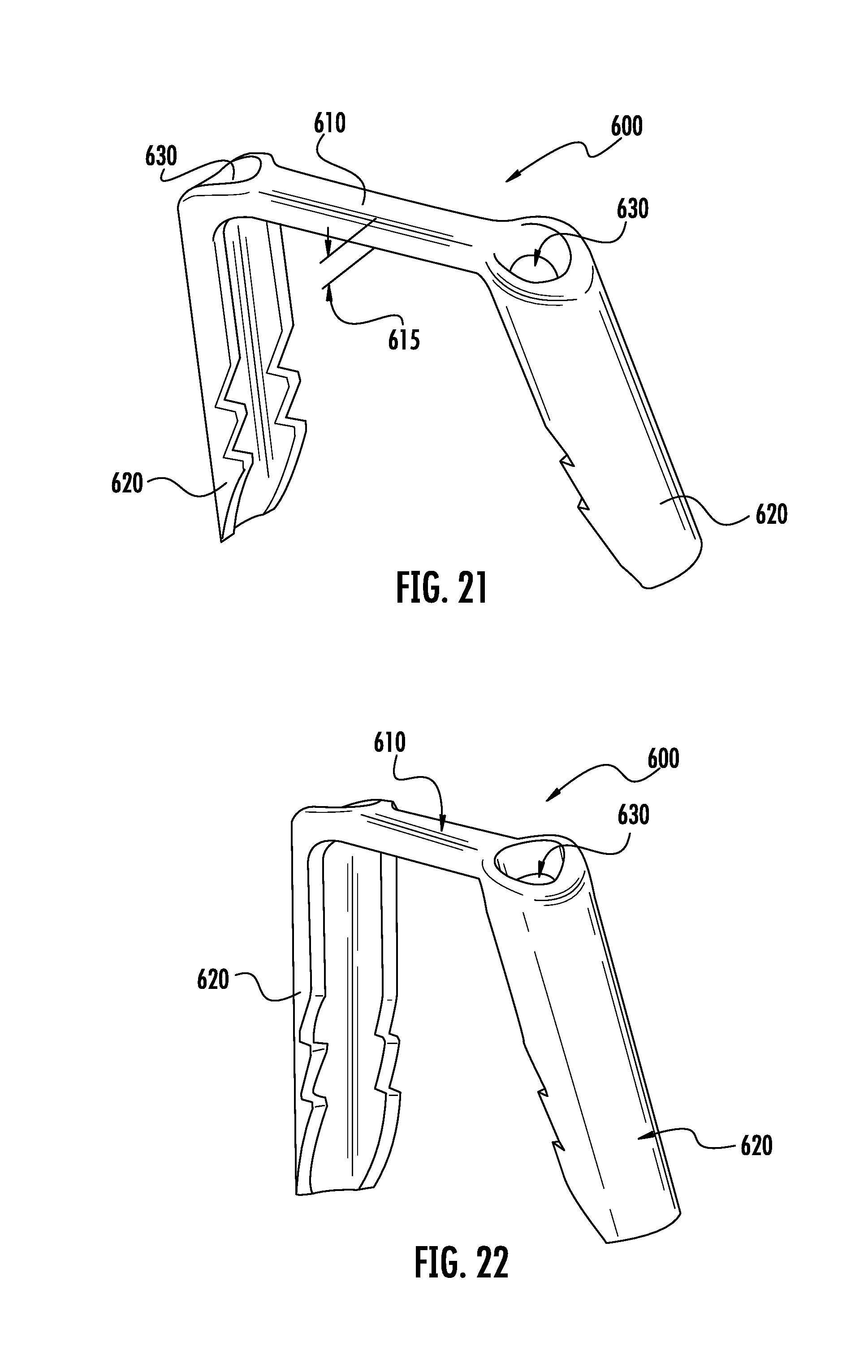
D00014

D00015
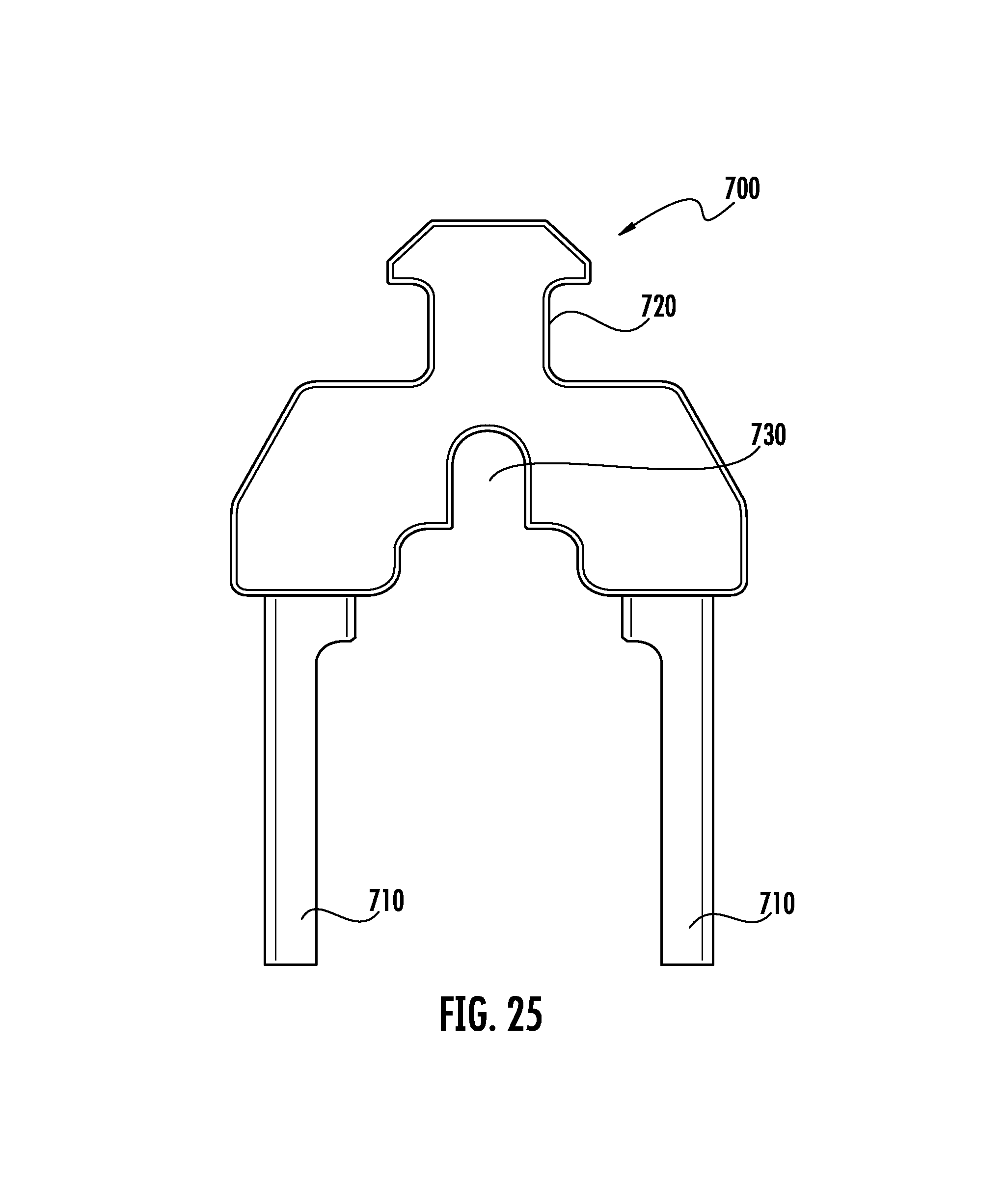
D00016

D00017

D00018

D00019

D00020

D00021

D00022
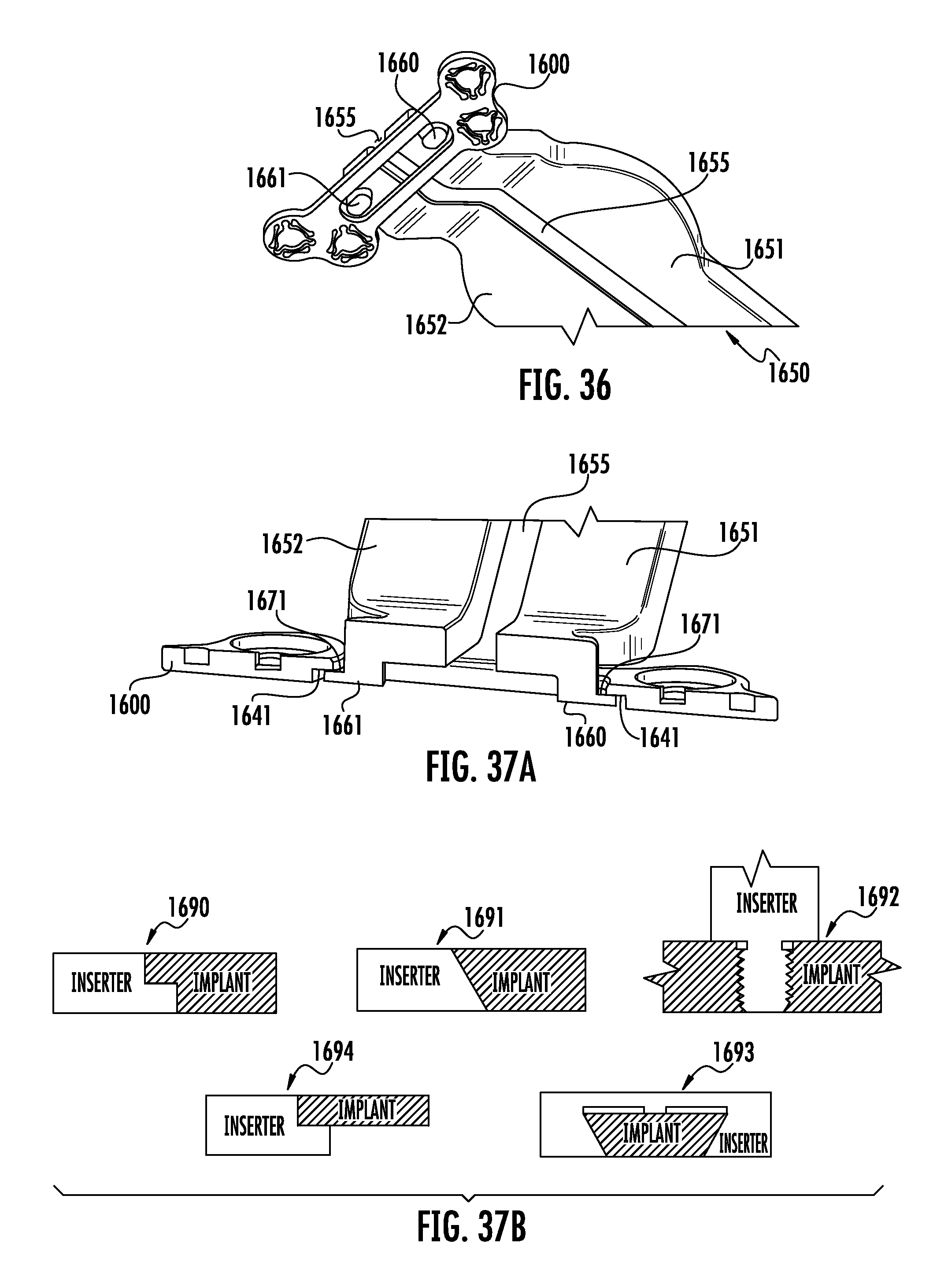
D00023
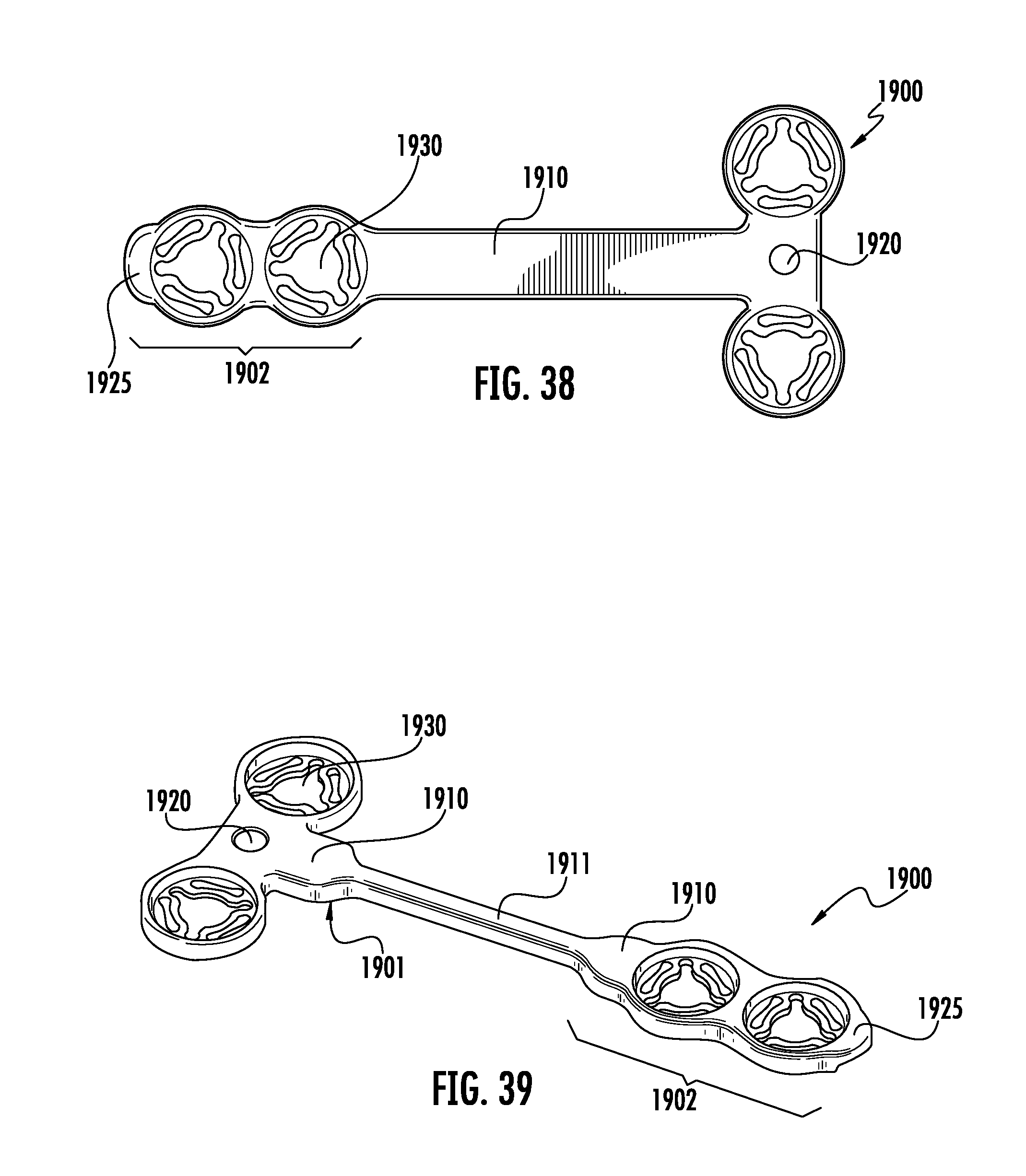
D00024
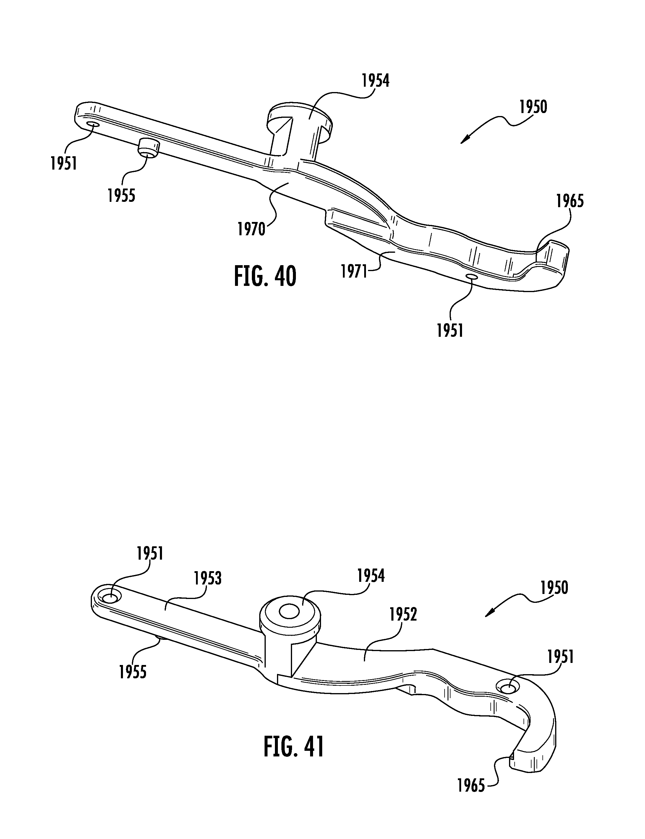
D00025
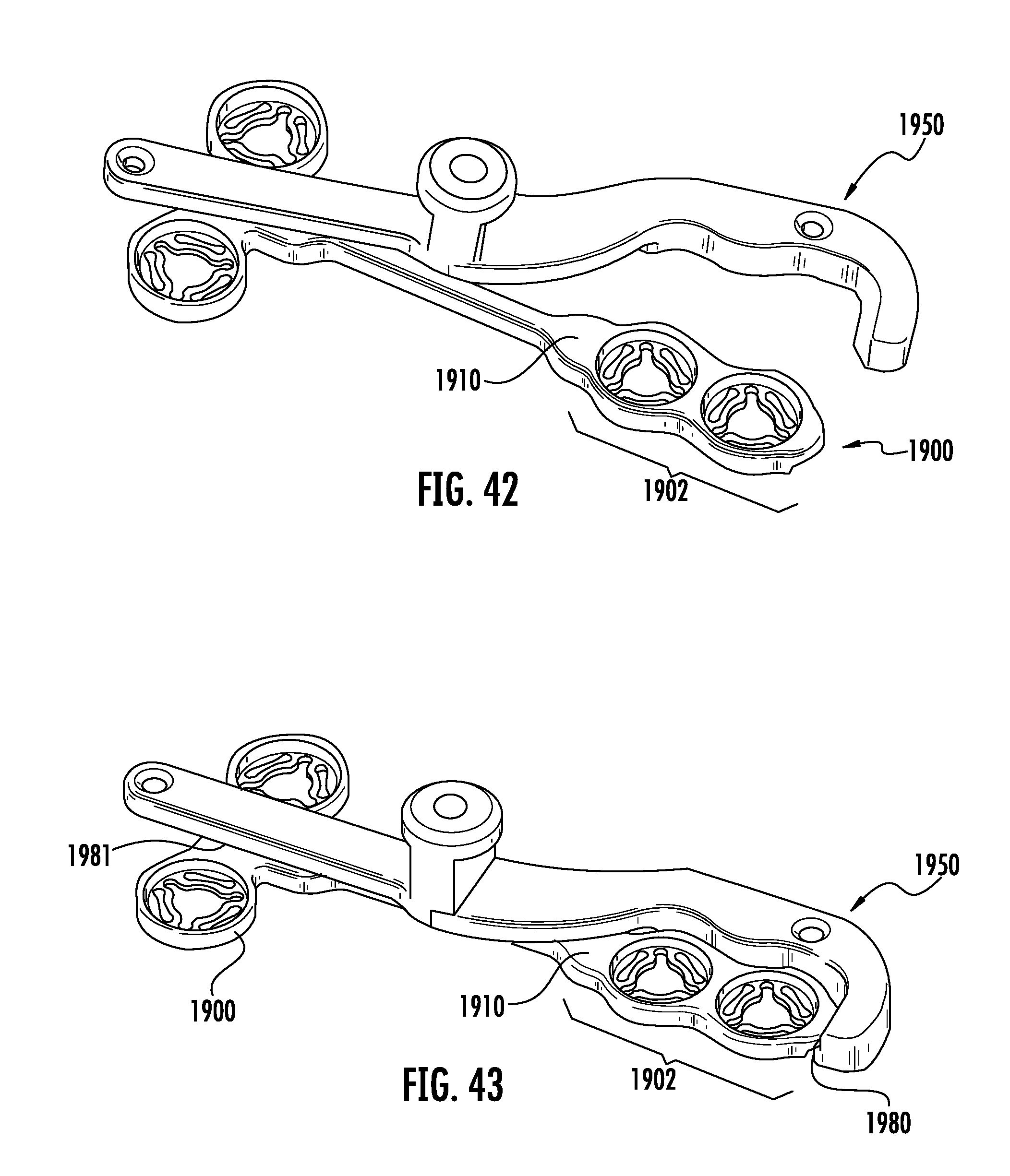
D00026
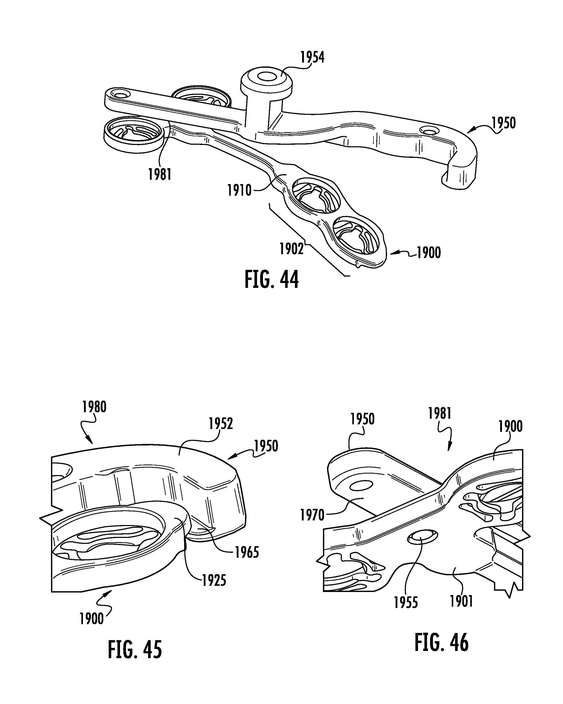
D00027

D00028

D00029

D00030

D00031
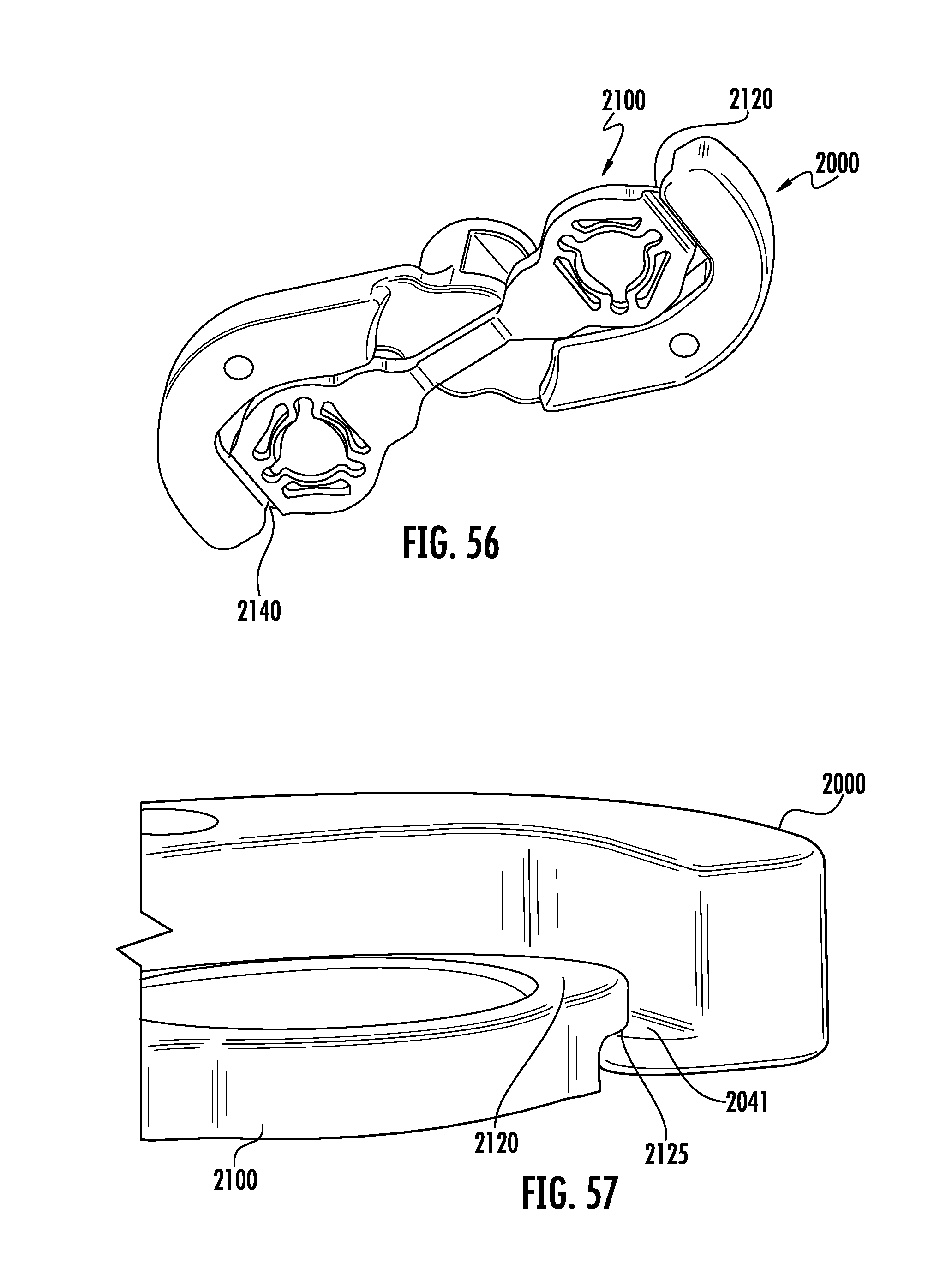
D00032

D00033

D00034
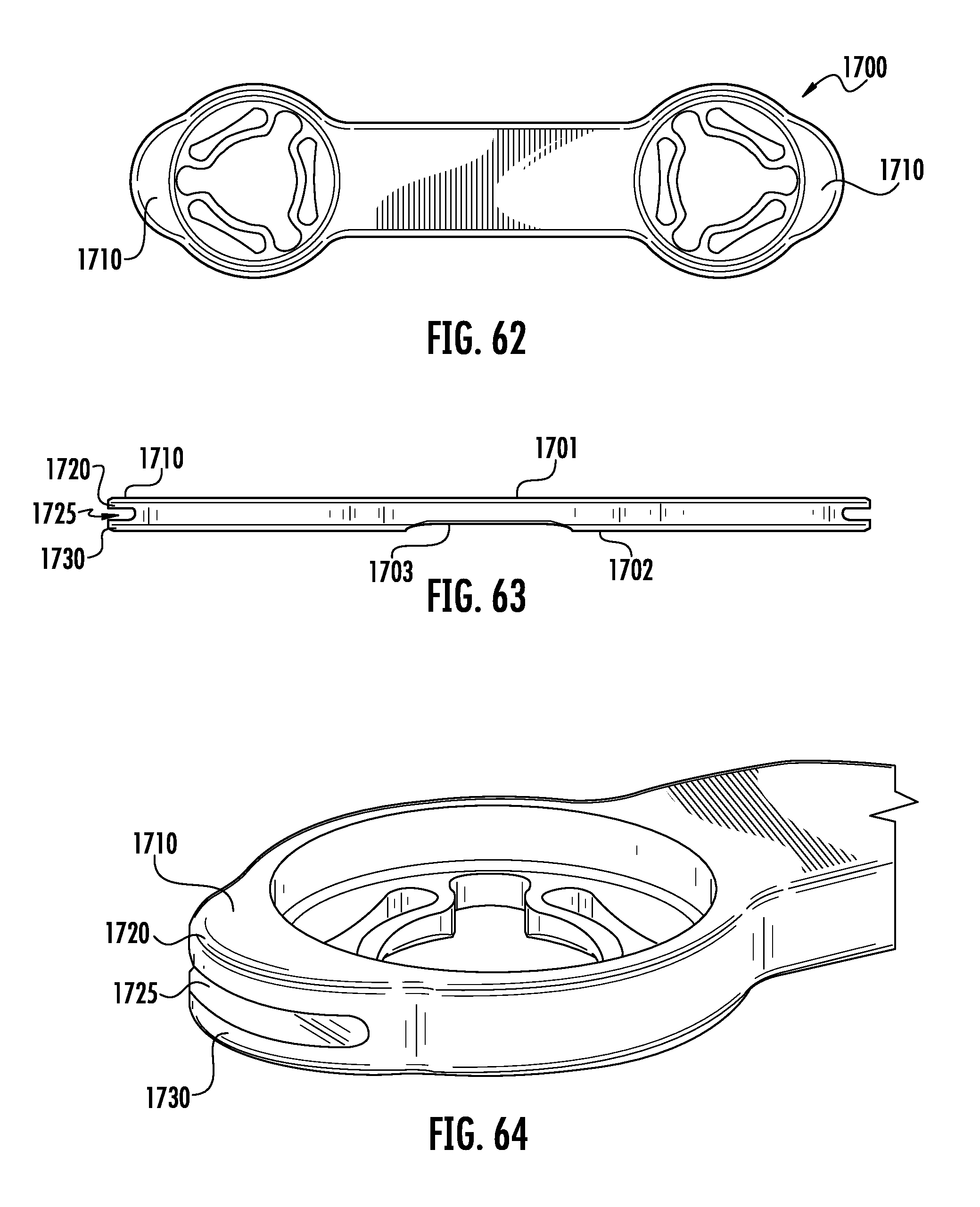
D00035

D00036

D00037
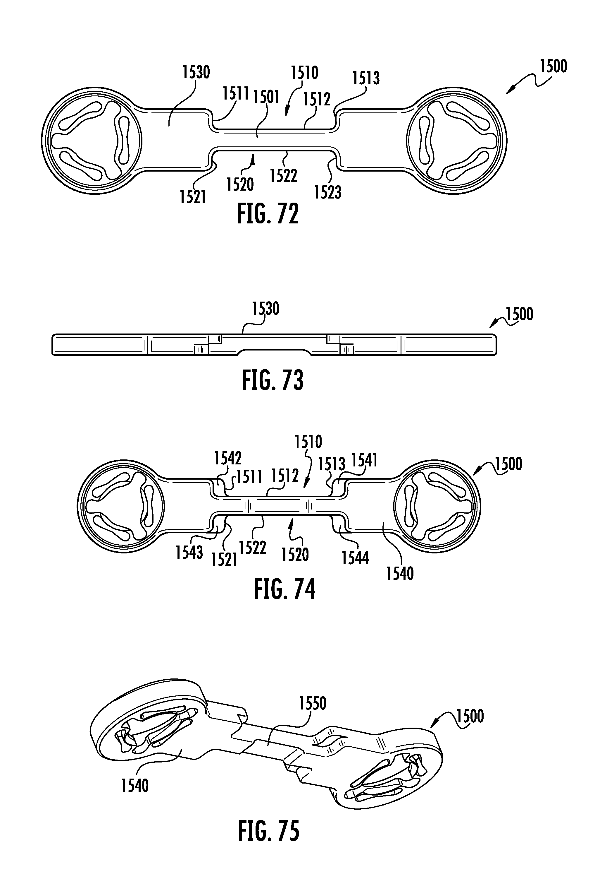
D00038
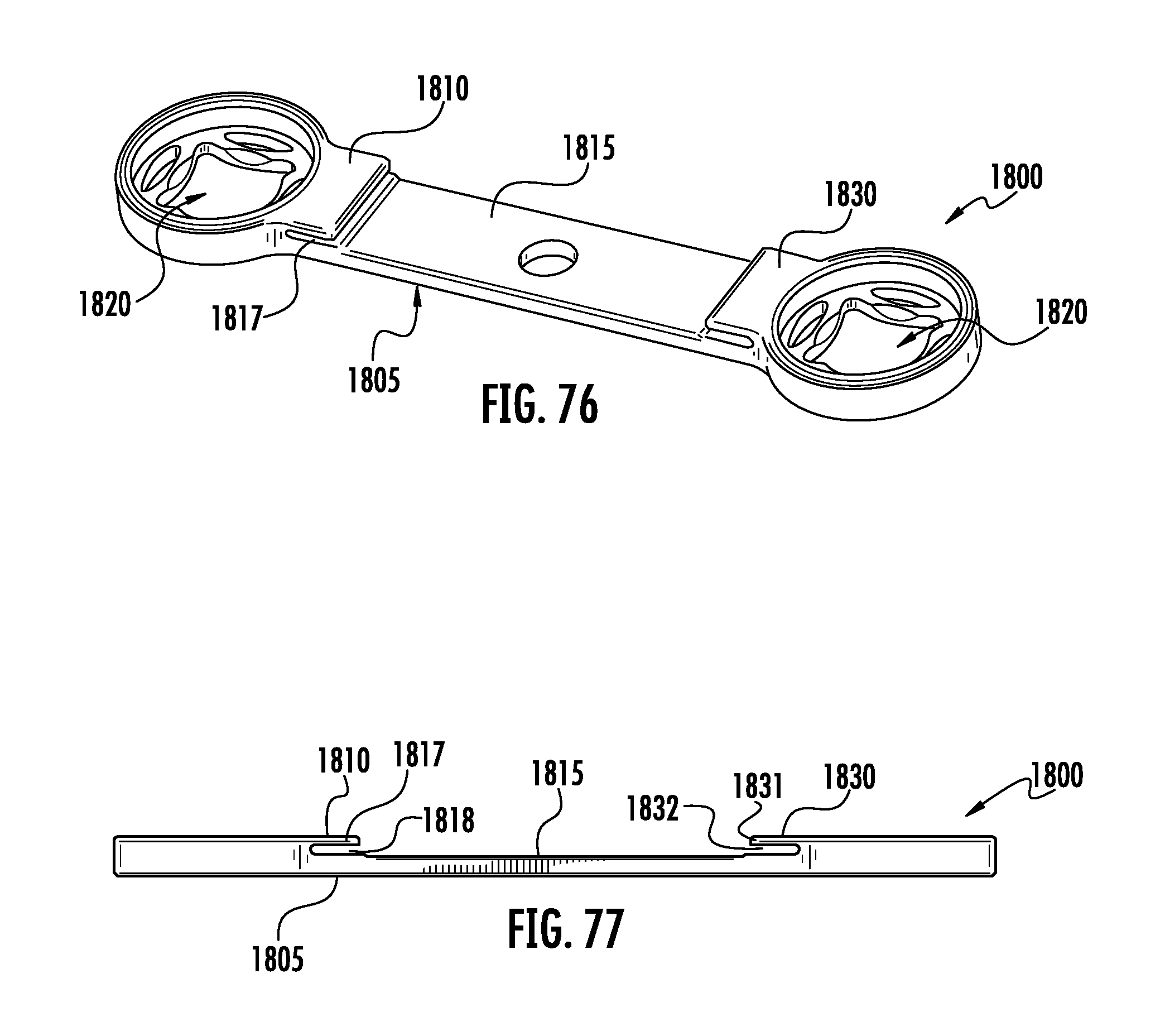
D00039
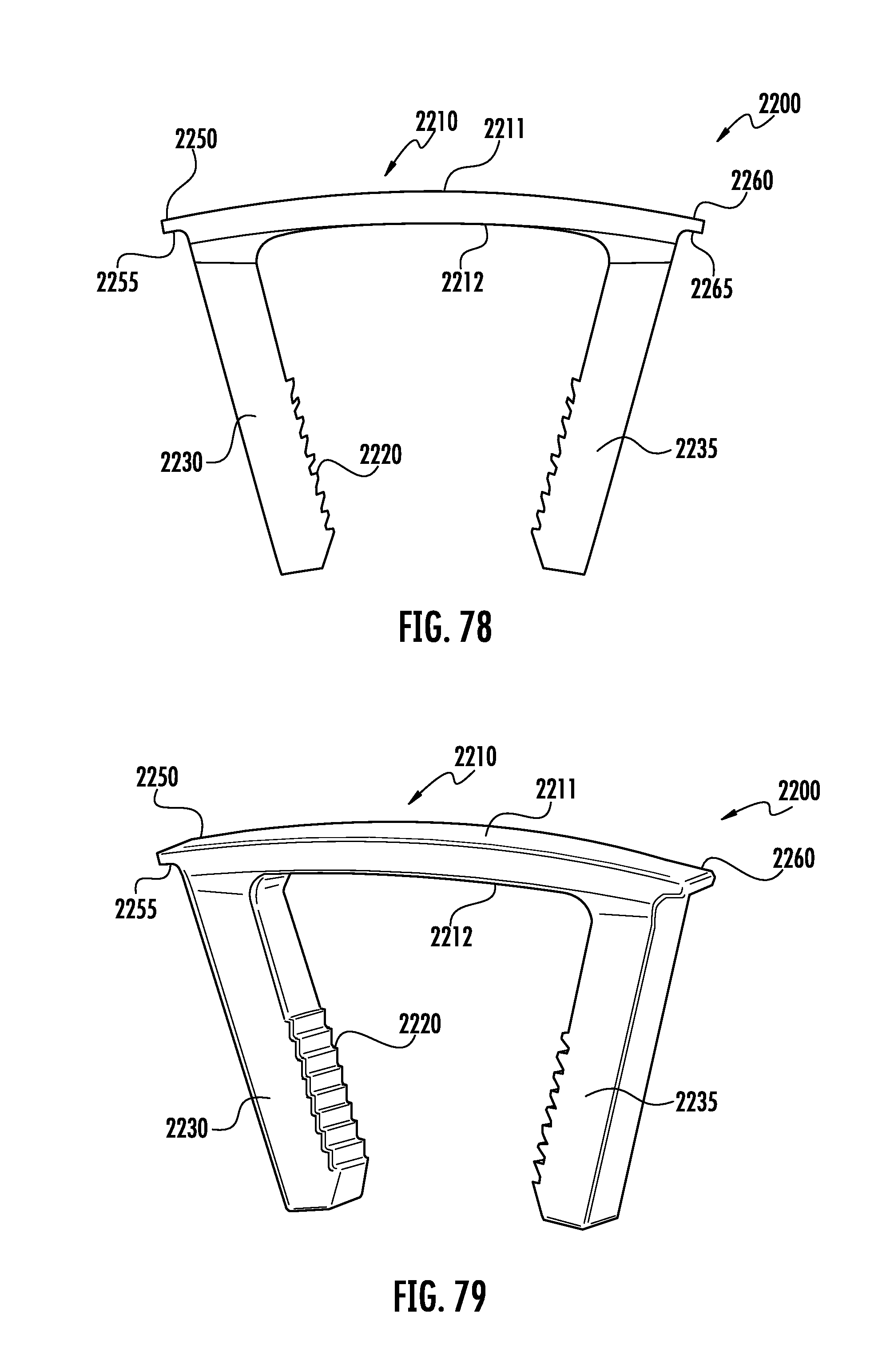
XML
uspto.report is an independent third-party trademark research tool that is not affiliated, endorsed, or sponsored by the United States Patent and Trademark Office (USPTO) or any other governmental organization. The information provided by uspto.report is based on publicly available data at the time of writing and is intended for informational purposes only.
While we strive to provide accurate and up-to-date information, we do not guarantee the accuracy, completeness, reliability, or suitability of the information displayed on this site. The use of this site is at your own risk. Any reliance you place on such information is therefore strictly at your own risk.
All official trademark data, including owner information, should be verified by visiting the official USPTO website at www.uspto.gov. This site is not intended to replace professional legal advice and should not be used as a substitute for consulting with a legal professional who is knowledgeable about trademark law.