Load distribution in data networks
Sankar , et al. Nov
U.S. patent number 10,491,523 [Application Number 15/645,292] was granted by the patent office on 2019-11-26 for load distribution in data networks. This patent grant is currently assigned to A10 Networks, Inc.. The grantee listed for this patent is A10 NETWORKS, INC.. Invention is credited to Rahul Gupta, Rajkumar Jalan, Gurudeep Kamat, Hasnain Karampurwala, Rishi Sampat, Swaminathan Sankar.


| United States Patent | 10,491,523 |
| Sankar , et al. | November 26, 2019 |
Load distribution in data networks
Abstract
Provided are methods and systems for load distribution in a data network. A method for load distribution in the data network comprises retrieving network data associated with the data network and service node data associated with one or more service nodes. The method further comprises analyzing the retrieved network data and service node data. Based on the analysis, a service policy is generated. Upon receiving one or more service requests, the one or more service requests are distributed among the service nodes according to the service policy.
| Inventors: | Sankar; Swaminathan (San Jose, CA), Karampurwala; Hasnain (San Clara, CA), Gupta; Rahul (Fremont, CA), Kamat; Gurudeep (San Jose, CA), Sampat; Rishi (San Clara, CA), Jalan; Rajkumar (Saratoga, CA) | ||||||||||
|---|---|---|---|---|---|---|---|---|---|---|---|
| Applicant: |
|
||||||||||
| Assignee: | A10 Networks, Inc. (San Jose,
CA) |
||||||||||
| Family ID: | 50340031 | ||||||||||
| Appl. No.: | 15/645,292 | ||||||||||
| Filed: | July 10, 2017 |
Prior Publication Data
| Document Identifier | Publication Date | |
|---|---|---|
| US 20170310596 A1 | Oct 26, 2017 | |
Related U.S. Patent Documents
| Application Number | Filing Date | Patent Number | Issue Date | ||
|---|---|---|---|---|---|
| 14029656 | Sep 17, 2013 | 9705800 | |||
| 14279270 | May 15, 2014 | 10021174 | |||
| 14029656 | Sep 17, 2013 | 9705800 | |||
| 13716128 | Dec 15, 2012 | 9106561 | |||
| 14320420 | Jun 30, 2014 | 10002141 | |||
| 14029656 | Sep 17, 2013 | 9705800 | |||
| 15645292 | |||||
| 14326325 | Jul 8, 2014 | 9843484 | |||
| 14029656 | Sep 17, 2013 | 9705800 | |||
| 61705618 | Sep 25, 2012 | ||||
| Current U.S. Class: | 1/1 |
| Current CPC Class: | H04L 67/1031 (20130101); H04L 67/101 (20130101); H04L 67/1025 (20130101); H04L 67/1012 (20130101); H04L 47/125 (20130101) |
| Current International Class: | G06F 15/173 (20060101); H04L 29/08 (20060101); H04L 12/803 (20130101) |
| Field of Search: | ;709/224 |
References Cited [Referenced By]
U.S. Patent Documents
| 5218602 | June 1993 | Grant et al. |
| 5432908 | July 1995 | Heddes et al. |
| 5774660 | June 1998 | Brendel et al. |
| 5781550 | July 1998 | Templin et al. |
| 5875185 | February 1999 | Wang et al. |
| 5931914 | August 1999 | Chiu |
| 5935207 | August 1999 | Logue et al. |
| 5958053 | September 1999 | Denker |
| 5995981 | November 1999 | Wikstrom |
| 6003069 | December 1999 | Cavill |
| 6047268 | April 2000 | Bartoli et al. |
| 6131163 | October 2000 | Wiegel |
| 6141749 | October 2000 | Coss et al. |
| 6167428 | December 2000 | Ellis |
| 6219706 | April 2001 | Fan et al. |
| 6259705 | July 2001 | Takashi et al. |
| 6321338 | November 2001 | Porras et al. |
| 6324286 | November 2001 | Lai et al. |
| 6360265 | March 2002 | Falck et al. |
| 6363075 | March 2002 | Huang et al. |
| 6374300 | April 2002 | Masters |
| 6389462 | May 2002 | Cohen et al. |
| 6415329 | July 2002 | Gelman et al. |
| 6459682 | October 2002 | Ellesson et al. |
| 6519243 | February 2003 | Nonaka et al. |
| 6535516 | March 2003 | Leu et al. |
| 6578066 | June 2003 | Logan et al. |
| 6587866 | July 2003 | Modi et al. |
| 6658114 | December 2003 | Farn et al. |
| 6728748 | April 2004 | Mangipudi et al. |
| 6748414 | June 2004 | Bournas |
| 6772334 | August 2004 | Glawitsch |
| 6779017 | August 2004 | Lamberton et al. |
| 6779033 | August 2004 | Watson et al. |
| 6832322 | December 2004 | Boden et al. |
| 6952728 | October 2005 | Alles et al. |
| 7010605 | March 2006 | Dharmarajan |
| 7013338 | March 2006 | Nag et al. |
| 7013482 | March 2006 | Krumel |
| 7058718 | June 2006 | Fontes et al. |
| 7058789 | June 2006 | Henderson et al. |
| 7058973 | June 2006 | Sultan |
| 7069438 | June 2006 | Balabine et al. |
| 7076555 | July 2006 | Orman et al. |
| 7086086 | August 2006 | Ellis |
| 7111162 | September 2006 | Bagepalli et al. |
| 7143087 | November 2006 | Fairweather |
| 7167927 | January 2007 | Philbrick et al. |
| 7181524 | February 2007 | Lele |
| 7218722 | May 2007 | Turner et al. |
| 7228359 | June 2007 | Monteiro |
| 7234161 | June 2007 | Maufer et al. |
| 7236457 | June 2007 | Joe |
| 7254133 | August 2007 | Govindarajan et al. |
| 7266604 | September 2007 | Nathan et al. |
| 7269850 | September 2007 | Govindarajan et al. |
| 7277963 | October 2007 | Dolson et al. |
| 7284272 | October 2007 | Howard et al. |
| 7290050 | October 2007 | Smith et al. |
| 7301899 | November 2007 | Goldstone |
| 7308499 | December 2007 | Chavez |
| 7308710 | December 2007 | Yarborough |
| 7310686 | December 2007 | Uysal |
| 7328267 | February 2008 | Bashyam et al. |
| 7334232 | February 2008 | Jacobs et al. |
| 7337241 | February 2008 | Boucher et al. |
| 7343399 | March 2008 | Hayball et al. |
| 7349970 | March 2008 | Clement et al. |
| 7370100 | May 2008 | Gunturu |
| 7370353 | May 2008 | Yang |
| 7373500 | May 2008 | Ramelson et al. |
| 7391725 | June 2008 | Huitema et al. |
| 7398317 | July 2008 | Chen et al. |
| 7406709 | July 2008 | Maher, III et al. |
| 7423977 | September 2008 | Joshi |
| 7430755 | September 2008 | Hughes et al. |
| 7441270 | October 2008 | Edwards et al. |
| 7451312 | November 2008 | Medvinsky et al. |
| 7463648 | December 2008 | Eppstein et al. |
| 7467202 | December 2008 | Savchuk |
| 7472190 | December 2008 | Robinson |
| 7492766 | February 2009 | Cabeca et al. |
| 7506360 | March 2009 | Wilkinson et al. |
| 7509369 | March 2009 | Tormasov |
| 7512980 | March 2009 | Copeland et al. |
| 7516485 | April 2009 | Lee et al. |
| 7529242 | May 2009 | Lyle |
| 7533409 | May 2009 | Keane et al. |
| 7552323 | June 2009 | Shay |
| 7568041 | July 2009 | Turner et al. |
| 7583668 | September 2009 | Mayes et al. |
| 7584262 | September 2009 | Wang et al. |
| 7584301 | September 2009 | Joshi |
| 7590736 | September 2009 | Hydrie et al. |
| 7591001 | September 2009 | Shay |
| 7603454 | October 2009 | Piper |
| 7613193 | November 2009 | Swami et al. |
| 7613822 | November 2009 | Joy et al. |
| 7673072 | March 2010 | Boucher et al. |
| 7675854 | March 2010 | Chen et al. |
| 7703102 | April 2010 | Eppstein et al. |
| 7707295 | April 2010 | Szeto et al. |
| 7711790 | May 2010 | Barrett et al. |
| 7716369 | May 2010 | Le Pennec et al. |
| 7739395 | June 2010 | Parlamas et al. |
| 7747748 | June 2010 | Allen |
| 7751409 | July 2010 | Carolan |
| 7765328 | July 2010 | Bryers et al. |
| 7779130 | August 2010 | Toutonghi |
| 7792113 | September 2010 | Foschiano et al. |
| 7808994 | October 2010 | Vinokour et al. |
| 7826487 | November 2010 | Mukerji et al. |
| 7881215 | February 2011 | Daigle et al. |
| 7908651 | March 2011 | Maher |
| 7948952 | May 2011 | Hurtta et al. |
| 7965727 | June 2011 | Sakata et al. |
| 7970934 | June 2011 | Patel |
| 7983258 | July 2011 | Ruben et al. |
| 7990847 | August 2011 | Leroy et al. |
| 7991859 | August 2011 | Miller et al. |
| 8019870 | September 2011 | Eppstein et al. |
| 8032634 | October 2011 | Eppstein et al. |
| 8079077 | December 2011 | Chen et al. |
| 8090866 | January 2012 | Bashyam et al. |
| 8122116 | February 2012 | Matsunaga et al. |
| 8179809 | May 2012 | Eppstein et al. |
| 8185651 | May 2012 | Moran et al. |
| 8191106 | May 2012 | Choyi et al. |
| 8224971 | July 2012 | Miller et al. |
| 8244876 | August 2012 | Sollee |
| 8255644 | August 2012 | Sonnier et al. |
| 8266235 | September 2012 | Jalan et al. |
| 8291487 | October 2012 | Chen et al. |
| 8296434 | October 2012 | Miller et al. |
| 8312507 | November 2012 | Chen et al. |
| 8327128 | December 2012 | Prince et al. |
| 8332925 | December 2012 | Chen et al. |
| 8347392 | January 2013 | Chess et al. |
| 8379515 | February 2013 | Mukerji |
| 8387128 | February 2013 | Chen et al. |
| 8412832 | April 2013 | Narayana |
| 8464333 | June 2013 | Chen et al. |
| 8499093 | July 2013 | Grosser et al. |
| 8520615 | August 2013 | Mehta et al. |
| 8539075 | September 2013 | Bali et al. |
| 8554929 | October 2013 | Szeto et al. |
| 8560693 | October 2013 | Wang et al. |
| 8584199 | November 2013 | Chen et al. |
| 8595383 | November 2013 | Chen et al. |
| 8595791 | November 2013 | Chen et al. |
| 8595819 | November 2013 | Chen et al. |
| RE44701 | January 2014 | Chen et al. |
| 8675488 | March 2014 | Sidebottom et al. |
| 8681610 | March 2014 | Mukerji |
| 8750164 | June 2014 | Casado et al. |
| 8782221 | July 2014 | Han |
| 8813180 | August 2014 | Chen et al. |
| 8826372 | September 2014 | Chen et al. |
| 8879427 | November 2014 | Krumel |
| 8885463 | November 2014 | Medved et al. |
| 8897154 | November 2014 | Jalan et al. |
| 8904512 | December 2014 | Chen et al. |
| 8914871 | December 2014 | Chen et al. |
| 8918857 | December 2014 | Chen et al. |
| 8943577 | January 2015 | Chen et al. |
| 8965957 | February 2015 | Barros |
| 8977749 | March 2015 | Han |
| 8990262 | March 2015 | Chen et al. |
| 9032502 | May 2015 | Chen et al. |
| 9094364 | July 2015 | Jalan et al. |
| 9106561 | August 2015 | Jalan et al. |
| 9118618 | August 2015 | Davis |
| 9118620 | August 2015 | Davis |
| 9124550 | September 2015 | Chen et al. |
| 9154577 | October 2015 | Jalan et al. |
| 9154584 | October 2015 | Han |
| 9215275 | December 2015 | Kannan et al. |
| 9219751 | December 2015 | Chen et al. |
| 9253152 | February 2016 | Chen et al. |
| 9270705 | February 2016 | Chen et al. |
| 9270774 | February 2016 | Jalan et al. |
| 9338225 | May 2016 | Jalan et al. |
| 9350744 | May 2016 | Chen et al. |
| 9356910 | May 2016 | Chen et al. |
| 9386088 | July 2016 | Zheng et al. |
| 9559964 | January 2017 | Hartrick |
| 9609052 | March 2017 | Jalan et al. |
| 2001/0015812 | August 2001 | Sugaya |
| 2001/0049741 | December 2001 | Skene et al. |
| 2002/0026531 | February 2002 | Keane et al. |
| 2002/0032777 | March 2002 | Kawata et al. |
| 2002/0046348 | April 2002 | Brustoloni |
| 2002/0053031 | May 2002 | Bendinelli et al. |
| 2002/0078164 | June 2002 | Reinschmidt |
| 2002/0091844 | July 2002 | Craft et al. |
| 2002/0103916 | August 2002 | Chen et al. |
| 2002/0133491 | September 2002 | Sim et al. |
| 2002/0138618 | September 2002 | Szabo |
| 2002/0141448 | October 2002 | Matsunaga |
| 2002/0143991 | October 2002 | Chow et al. |
| 2002/0178259 | November 2002 | Doyle et al. |
| 2002/0191575 | December 2002 | Kalavade et al. |
| 2002/0194335 | December 2002 | Maynard |
| 2002/0194350 | December 2002 | Lu et al. |
| 2003/0009591 | January 2003 | Hayball et al. |
| 2003/0014544 | January 2003 | Pettey et al. |
| 2003/0023711 | January 2003 | Parmar et al. |
| 2003/0023873 | January 2003 | Ben-Itzhak |
| 2003/0035409 | February 2003 | Wang et al. |
| 2003/0035420 | February 2003 | Nu |
| 2003/0065762 | April 2003 | Stolorz et al. |
| 2003/0065950 | April 2003 | Yarborough |
| 2003/0081624 | May 2003 | Aggarwal et al. |
| 2003/0088788 | May 2003 | Yang |
| 2003/0091028 | May 2003 | Chang et al. |
| 2003/0131245 | July 2003 | Linderman |
| 2003/0135625 | July 2003 | Fontes et al. |
| 2003/0135653 | July 2003 | Marovich |
| 2003/0152078 | August 2003 | Henderson et al. |
| 2003/0167340 | September 2003 | Jonsson |
| 2003/0195962 | October 2003 | Kikuchi et al. |
| 2003/0229809 | December 2003 | Wexler et al. |
| 2004/0054920 | March 2004 | Wilson et al. |
| 2004/0062246 | April 2004 | Boucher et al. |
| 2004/0073703 | April 2004 | Boucher et al. |
| 2004/0078419 | April 2004 | Ferrari et al. |
| 2004/0078480 | April 2004 | Boucher et al. |
| 2004/0107360 | June 2004 | Herrmann et al. |
| 2004/0111516 | June 2004 | Cain |
| 2004/0128312 | July 2004 | Shalabi et al. |
| 2004/0139057 | July 2004 | Hirata et al. |
| 2004/0139108 | July 2004 | Tang et al. |
| 2004/0141005 | July 2004 | Banatwala et al. |
| 2004/0143599 | July 2004 | Shalabi et al. |
| 2004/0184442 | September 2004 | Jones et al. |
| 2004/0187032 | September 2004 | Gels et al. |
| 2004/0199616 | October 2004 | Karhu |
| 2004/0199646 | October 2004 | Susai et al. |
| 2004/0202182 | October 2004 | Lund |
| 2004/0210623 | October 2004 | Hydrie et al. |
| 2004/0210663 | October 2004 | Phillips et al. |
| 2004/0213158 | October 2004 | Collett et al. |
| 2004/0243718 | December 2004 | Fujiyoshi |
| 2004/0268358 | December 2004 | Darling et al. |
| 2005/0005207 | January 2005 | Herneque |
| 2005/0009520 | January 2005 | Herrero et al. |
| 2005/0021848 | January 2005 | Jorgenson |
| 2005/0027862 | February 2005 | Nguyen et al. |
| 2005/0027947 | February 2005 | Landin |
| 2005/0033985 | February 2005 | Xu et al. |
| 2005/0036501 | February 2005 | Chung et al. |
| 2005/0036511 | February 2005 | Baratakke et al. |
| 2005/0038898 | February 2005 | Mittig et al. |
| 2005/0044270 | February 2005 | Grove et al. |
| 2005/0050364 | March 2005 | Feng |
| 2005/0074001 | April 2005 | Mattes |
| 2005/0074013 | April 2005 | Hershey et al. |
| 2005/0080890 | April 2005 | Yang et al. |
| 2005/0102400 | May 2005 | Nakahara et al. |
| 2005/0114492 | May 2005 | Arberg |
| 2005/0125276 | June 2005 | Rusu |
| 2005/0135422 | June 2005 | Yeh |
| 2005/0144468 | June 2005 | Northcutt et al. |
| 2005/0163073 | July 2005 | Heller et al. |
| 2005/0169285 | August 2005 | Wills et al. |
| 2005/0198335 | September 2005 | Brown et al. |
| 2005/0213586 | September 2005 | Cyganski et al. |
| 2005/0240989 | October 2005 | Kim et al. |
| 2005/0249225 | November 2005 | Singhal |
| 2005/0251856 | November 2005 | Araujo et al. |
| 2005/0259586 | November 2005 | Hafid et al. |
| 2005/0289231 | December 2005 | Harada et al. |
| 2006/0023721 | February 2006 | Miyake et al. |
| 2006/0031506 | February 2006 | Redgate |
| 2006/0036610 | February 2006 | Wang |
| 2006/0036733 | February 2006 | Fujimoto et al. |
| 2006/0062142 | March 2006 | Appanna et al. |
| 2006/0063517 | March 2006 | Oh et al. |
| 2006/0064440 | March 2006 | Perry |
| 2006/0064478 | March 2006 | Sirkin |
| 2006/0069774 | March 2006 | Chen et al. |
| 2006/0069804 | March 2006 | Miyake et al. |
| 2006/0077926 | April 2006 | Rune |
| 2006/0080446 | April 2006 | Bahl |
| 2006/0092950 | May 2006 | Arregoces et al. |
| 2006/0098645 | May 2006 | Walkin |
| 2006/0112170 | May 2006 | Sirkin |
| 2006/0126625 | June 2006 | Schollmeier et al. |
| 2006/0187901 | June 2006 | Cortes et al. |
| 2006/0168319 | July 2006 | Trossen |
| 2006/0190997 | August 2006 | Mahajani et al. |
| 2006/0195698 | August 2006 | Pinkerton et al. |
| 2006/0209789 | September 2006 | Gupta et al. |
| 2006/0227771 | October 2006 | Raghunath et al. |
| 2006/0230129 | October 2006 | Swami et al. |
| 2006/0233100 | October 2006 | Luft et al. |
| 2006/0251057 | November 2006 | Kwon et al. |
| 2006/0277303 | December 2006 | Hegde et al. |
| 2006/0280121 | December 2006 | Matoba |
| 2007/0002857 | January 2007 | Maher |
| 2007/0011419 | January 2007 | Conti |
| 2007/0019543 | January 2007 | Wei et al. |
| 2007/0086382 | April 2007 | Narayanan et al. |
| 2007/0094396 | April 2007 | Takano et al. |
| 2007/0118881 | May 2007 | Mitchell et al. |
| 2007/0124487 | May 2007 | Yoshimoto et al. |
| 2007/0156919 | July 2007 | Potti et al. |
| 2007/0165622 | July 2007 | O'Rourke et al. |
| 2007/0177506 | August 2007 | Singer |
| 2007/0180226 | August 2007 | Schory |
| 2007/0180513 | August 2007 | Raz et al. |
| 2007/0185998 | August 2007 | Touitou et al. |
| 2007/0195792 | August 2007 | Chen et al. |
| 2007/0230337 | October 2007 | Igarashi et al. |
| 2007/0245090 | October 2007 | King et al. |
| 2007/0259673 | November 2007 | Willars et al. |
| 2007/0283429 | December 2007 | Chen et al. |
| 2007/0286077 | December 2007 | Wu |
| 2007/0288247 | December 2007 | MacKay |
| 2007/0294209 | December 2007 | Strub et al. |
| 2007/0294694 | December 2007 | Jeter et al. |
| 2008/0031263 | February 2008 | Ervin et al. |
| 2008/0034111 | February 2008 | Kamath et al. |
| 2008/0034419 | February 2008 | Mullick et al. |
| 2008/0040789 | February 2008 | Chen et al. |
| 2008/0101396 | May 2008 | Miyata |
| 2008/0109452 | May 2008 | Patterson |
| 2008/0109870 | May 2008 | Sherlock et al. |
| 2008/0134332 | June 2008 | Keohane et al. |
| 2008/0162679 | July 2008 | Maher et al. |
| 2008/0216177 | September 2008 | Yokosato et al. |
| 2008/0228781 | September 2008 | Chen et al. |
| 2008/0250099 | October 2008 | Shen et al. |
| 2008/0263209 | October 2008 | Pisharody et al. |
| 2008/0271130 | October 2008 | Ramamoorthy |
| 2008/0282254 | November 2008 | Blander et al. |
| 2008/0289044 | November 2008 | Choi |
| 2008/0291911 | November 2008 | Lee et al. |
| 2009/0049198 | February 2009 | Blinn et al. |
| 2009/0049537 | February 2009 | Chen et al. |
| 2009/0070470 | March 2009 | Bauman et al. |
| 2009/0077651 | March 2009 | Poeluev |
| 2009/0092124 | April 2009 | Singhal et al. |
| 2009/0106830 | April 2009 | Maher |
| 2009/0113536 | April 2009 | Zhang et al. |
| 2009/0138606 | May 2009 | Moran et al. |
| 2009/0138945 | May 2009 | Savchuk |
| 2009/0141634 | June 2009 | Rothstein et al. |
| 2009/0164614 | June 2009 | Christian et al. |
| 2009/0172093 | July 2009 | Matsubara |
| 2009/0210698 | August 2009 | Candelore |
| 2009/0213858 | August 2009 | Dolganow et al. |
| 2009/0222583 | September 2009 | Josefsberg |
| 2009/0227228 | September 2009 | Hu et al. |
| 2009/0228547 | September 2009 | Miyaoka et al. |
| 2009/0262741 | October 2009 | Jungck et al. |
| 2009/0271472 | October 2009 | Scheifler et al. |
| 2009/0313379 | December 2009 | Rydnell et al. |
| 2010/0004004 | January 2010 | Browne-Swinburne et al. |
| 2010/0008229 | January 2010 | Bi et al. |
| 2010/0023621 | January 2010 | Ezolt et al. |
| 2010/0036952 | February 2010 | Hazlewood et al. |
| 2010/0054139 | March 2010 | Chun et al. |
| 2010/0061319 | March 2010 | Aso et al. |
| 2010/0064008 | March 2010 | Yan et al. |
| 2010/0082787 | April 2010 | Kommula et al. |
| 2010/0083076 | April 2010 | Ushiyama |
| 2010/0094985 | April 2010 | Abu-Samaha et al. |
| 2010/0098417 | April 2010 | Tse-Au |
| 2010/0106833 | April 2010 | Banerjee |
| 2010/0106854 | April 2010 | Kim et al. |
| 2010/0128606 | May 2010 | Patel et al. |
| 2010/0162378 | June 2010 | Jayawardena et al. |
| 2010/0210265 | August 2010 | Borzsei et al. |
| 2010/0211669 | August 2010 | Dalgas et al. |
| 2010/0217793 | August 2010 | Preiss |
| 2010/0217819 | August 2010 | Chen et al. |
| 2010/0223630 | September 2010 | Degenkolb et al. |
| 2010/0228819 | September 2010 | Wei |
| 2010/0228878 | September 2010 | Xu et al. |
| 2010/0235507 | September 2010 | Szeto et al. |
| 2010/0235522 | September 2010 | Chen et al. |
| 2010/0235880 | September 2010 | Chen et al. |
| 2010/0238828 | September 2010 | Russell |
| 2010/0257278 | October 2010 | Gunturu |
| 2010/0265824 | October 2010 | Chao et al. |
| 2010/0268814 | October 2010 | Cross et al. |
| 2010/0293296 | November 2010 | Hsu et al. |
| 2010/0312740 | December 2010 | Clemm et al. |
| 2010/0318631 | December 2010 | Shukla et al. |
| 2010/0322252 | December 2010 | Suganthi et al. |
| 2010/0330971 | December 2010 | Selitser et al. |
| 2010/0333101 | December 2010 | Pope et al. |
| 2010/0333209 | December 2010 | Alve |
| 2011/0007652 | January 2011 | Bai |
| 2011/0019550 | January 2011 | Bryers |
| 2011/0023071 | January 2011 | Li et al. |
| 2011/0029599 | February 2011 | Pulleyn et al. |
| 2011/0032941 | February 2011 | Quach et al. |
| 2011/0040826 | February 2011 | Chadzelek et al. |
| 2011/0047294 | February 2011 | Singh et al. |
| 2011/0060831 | March 2011 | Ishii et al. |
| 2011/0060840 | March 2011 | Susai et al. |
| 2011/0093522 | April 2011 | Chen et al. |
| 2011/0099403 | April 2011 | Miyata et al. |
| 2011/0110294 | May 2011 | Valluri et al. |
| 2011/0125704 | May 2011 | Mordvinova |
| 2011/0145324 | June 2011 | Reinart et al. |
| 2011/0145390 | June 2011 | Kakadia et al. |
| 2011/0153834 | June 2011 | Bharrat |
| 2011/0178985 | July 2011 | San Martin Arribas et al. |
| 2011/0185073 | July 2011 | Jagadeeswaran et al. |
| 2011/0191773 | August 2011 | Pavel et al. |
| 2011/0196971 | August 2011 | Reguraman et al. |
| 2011/0226810 | September 2011 | Wang |
| 2011/0276695 | November 2011 | Maldaner |
| 2011/0276982 | November 2011 | Nakayama et al. |
| 2011/0289496 | November 2011 | Steer |
| 2011/0292939 | December 2011 | Subramaian et al. |
| 2011/0302256 | December 2011 | Sureshehandra et al. |
| 2011/0307541 | December 2011 | Walsh et al. |
| 2011/0307606 | December 2011 | Cobb |
| 2012/0008495 | January 2012 | Shen et al. |
| 2012/0023231 | January 2012 | Ueno |
| 2012/0026897 | February 2012 | Guichard et al. |
| 2012/0030341 | February 2012 | Jensen et al. |
| 2012/0066371 | March 2012 | Patel et al. |
| 2012/0084419 | April 2012 | Kannan et al. |
| 2012/0084460 | April 2012 | McGinnity et al. |
| 2012/0106355 | May 2012 | Ludwig |
| 2012/0117571 | May 2012 | Davis et al. |
| 2012/0144014 | June 2012 | Natham et al. |
| 2012/0144015 | June 2012 | Jalan et al. |
| 2012/0151353 | June 2012 | Joanny |
| 2012/0155495 | June 2012 | Clee et al. |
| 2012/0170548 | July 2012 | Rajagopalan et al. |
| 2012/0173759 | July 2012 | Agarwal et al. |
| 2012/0179770 | July 2012 | Jalan et al. |
| 2012/0191839 | July 2012 | Maynard |
| 2012/0215910 | August 2012 | Wada |
| 2012/0239792 | September 2012 | Banerjee et al. |
| 2012/0240185 | September 2012 | Kapoor et al. |
| 2012/0290727 | November 2012 | Tivig |
| 2012/0297046 | November 2012 | Raja et al. |
| 2012/0311116 | December 2012 | Jalan et al. |
| 2013/0046876 | February 2013 | Narayana et al. |
| 2013/0058335 | March 2013 | Koponen et al. |
| 2013/0074177 | March 2013 | Varadhan et al. |
| 2013/0083725 | April 2013 | Mallya et al. |
| 2013/0089099 | April 2013 | Pollock et al. |
| 2013/0100958 | April 2013 | Jalan et al. |
| 2013/0103817 | April 2013 | Koponen et al. |
| 2013/0124713 | May 2013 | Feinberg et al. |
| 2013/0136139 | May 2013 | Zheng et al. |
| 2013/0148500 | June 2013 | Sonoda et al. |
| 2013/0166762 | June 2013 | Jalan et al. |
| 2013/0173795 | July 2013 | McPherson |
| 2013/0176854 | July 2013 | Chisu et al. |
| 2013/0191486 | July 2013 | Someya et al. |
| 2013/0191548 | July 2013 | Boddukuri et al. |
| 2013/0198385 | August 2013 | Han et al. |
| 2013/0227165 | August 2013 | Liu |
| 2013/0250765 | September 2013 | Ehsan et al. |
| 2013/0250770 | September 2013 | Zou et al. |
| 2013/0258846 | October 2013 | Damola |
| 2013/0262702 | October 2013 | Davis |
| 2013/0268646 | October 2013 | Doron et al. |
| 2013/0282791 | October 2013 | Kruglick |
| 2013/0311686 | November 2013 | Fetterman et al. |
| 2013/0315241 | November 2013 | Kamat et al. |
| 2013/0336159 | December 2013 | Previdi et al. |
| 2014/0012972 | January 2014 | Han |
| 2014/0089500 | March 2014 | Sankar et al. |
| 2014/0164617 | June 2014 | Jalan et al. |
| 2014/0169168 | June 2014 | Jalan et al. |
| 2014/0207845 | July 2014 | Han et al. |
| 2014/0226658 | August 2014 | Kakadia et al. |
| 2014/0235249 | August 2014 | Jeong et al. |
| 2014/0248914 | September 2014 | Aoyagi et al. |
| 2014/0258465 | September 2014 | Li |
| 2014/0258536 | September 2014 | Chiong |
| 2014/0269728 | September 2014 | Jalan et al. |
| 2014/0286313 | September 2014 | Fu et al. |
| 2014/0298091 | October 2014 | Carlen et al. |
| 2014/0325649 | October 2014 | Zhang |
| 2014/0330982 | November 2014 | Jalan et al. |
| 2014/0334485 | November 2014 | Jain et al. |
| 2014/0359052 | December 2014 | Joachimpillai et al. |
| 2015/0039671 | February 2015 | Jalan et al. |
| 2015/0047012 | February 2015 | Chen et al. |
| 2015/0098333 | April 2015 | Lin et al. |
| 2015/0156223 | June 2015 | Xu et al. |
| 2015/0215436 | July 2015 | Kancherla |
| 2015/0237173 | August 2015 | Virkki et al. |
| 2015/0281087 | October 2015 | Jalan et al. |
| 2015/0281104 | October 2015 | Golshan et al. |
| 2015/0296058 | October 2015 | Jalan et al. |
| 2015/0312268 | October 2015 | ay |
| 2015/0333988 | November 2015 | Jalan et al. |
| 2015/0350048 | December 2015 | Sampat et al. |
| 2015/0350379 | December 2015 | Jalan et al. |
| 2016/0014052 | January 2016 | Han |
| 2016/0036778 | February 2016 | Chen et al. |
| 2016/0042014 | February 2016 | Jalan et al. |
| 2016/0043901 | February 2016 | Sankar et al. |
| 2016/0044095 | February 2016 | Sankar et al. |
| 2016/0050233 | February 2016 | Chen et al. |
| 2016/0088074 | March 2016 | Kannan et al. |
| 2016/0094470 | March 2016 | Skog |
| 2016/0105395 | April 2016 | Chen et al. |
| 2016/0105446 | April 2016 | Chen et al. |
| 2016/0119382 | April 2016 | Chen et al. |
| 2016/0139910 | May 2016 | Ramanathan et al. |
| 2016/0156708 | June 2016 | Jalan et al. |
| 2016/0164792 | June 2016 | Oran |
| 2016/0173579 | June 2016 | Jalan et al. |
| 1372662 | Oct 2002 | CN | |||
| 1449618 | Oct 2003 | CN | |||
| 1473300 | Feb 2004 | CN | |||
| 1529460 | Sep 2004 | CN | |||
| 1575582 | Feb 2005 | CN | |||
| 1714545 | Dec 2005 | CN | |||
| 1725702 | Jan 2006 | CN | |||
| 1910869 | Feb 2007 | CN | |||
| 1921457 | Feb 2007 | CN | |||
| 1937591 | Mar 2007 | CN | |||
| 101004740 | Jul 2007 | CN | |||
| 101094225 | Dec 2007 | CN | |||
| 101163336 | Apr 2008 | CN | |||
| 101169785 | Apr 2008 | CN | |||
| 101189598 | May 2008 | CN | |||
| 101193089 | Jun 2008 | CN | |||
| 101247349 | Aug 2008 | CN | |||
| 101261644 | Sep 2008 | CN | |||
| 101495993 | Jul 2009 | CN | |||
| 101878663 | Nov 2010 | CN | |||
| 102143075 | Aug 2011 | CN | |||
| 102546590 | Jul 2012 | CN | |||
| 102571742 | Jul 2012 | CN | |||
| 102577252 | Jul 2012 | CN | |||
| 102918801 | Feb 2013 | CN | |||
| 103365654 | Oct 2013 | CN | |||
| 103428261 | Dec 2013 | CN | |||
| 103533018 | Jan 2014 | CN | |||
| 101878663 | Jun 2014 | CN | |||
| 103944954 | Jul 2014 | CN | |||
| 104040990 | Sep 2014 | CN | |||
| 104067569 | Sep 2014 | CN | |||
| 104106241 | Oct 2014 | CN | |||
| 104137491 | Nov 2014 | CN | |||
| 104796396 | Jul 2015 | CN | |||
| 102577252 | Mar 2016 | CN | |||
| 102918801 | May 2016 | CN | |||
| 102571742 | Jul 2016 | CN | |||
| 104067569 | Feb 2017 | CN | |||
| 1209876 | May 2002 | EP | |||
| 1482685 | Dec 2004 | EP | |||
| 1720287 | Nov 2006 | EP | |||
| 1770915 | Apr 2007 | EP | |||
| 1885096 | Feb 2008 | EP | |||
| 2057552 | May 2009 | EP | |||
| 2215863 | Aug 2010 | EP | |||
| 2296313 | Mar 2011 | EP | |||
| 2577910 | Apr 2013 | EP | |||
| 2622795 | Aug 2013 | EP | |||
| 2647174 | Oct 2013 | EP | |||
| 2667571 | Nov 2013 | EP | |||
| 2760170 | Jul 2014 | EP | |||
| 2772026 | Sep 2014 | EP | |||
| 2575328 | Nov 2014 | EP | |||
| 2901308 | Aug 2015 | EP | |||
| 2760170 | Dec 2015 | EP | |||
| 1182560 | Nov 2013 | HK | |||
| 1183569 | Dec 2013 | HK | |||
| 1183996 | Jan 2014 | HK | |||
| 1188498 | May 2014 | HK | |||
| 1189438 | Jun 2014 | HK | |||
| 1190539 | Jul 2014 | HK | |||
| 1182547 | Apr 2015 | HK | |||
| 1198565 | May 2015 | HK | |||
| 1198848 | Jun 2015 | HK | |||
| 1199153 | Jun 2015 | HK | |||
| 1199779 | Jul 2015 | HK | |||
| 1200617 | Aug 2015 | HK | |||
| 3764CHN2014 | Sep 2015 | IN | |||
| 261CHE2014 | Jul 2016 | IN | |||
| 1668CHENP2015 | Jul 2016 | IN | |||
| H0997233 | Apr 1997 | JP | |||
| H1196128 | Apr 1999 | JP | |||
| H11338836 | Dec 1999 | JP | |||
| 2000276432 | Oct 2000 | JP | |||
| 2000307634 | Nov 2000 | JP | |||
| 2001051859 | Feb 2001 | JP | |||
| 2001298449 | Oct 2001 | JP | |||
| 2002091936 | Mar 2002 | JP | |||
| 2003141068 | May 2003 | JP | |||
| 2003186776 | Jul 2003 | JP | |||
| 2004350188 | Dec 2004 | JP | |||
| 2005141441 | Jun 2005 | JP | |||
| 2005518595 | Jun 2005 | JP | |||
| 2006180295 | Jul 2006 | JP | |||
| 2006332825 | Dec 2006 | JP | |||
| 2006333245 | Dec 2006 | JP | |||
| 2007048052 | Feb 2007 | JP | |||
| 2008040718 | Feb 2008 | JP | |||
| 2009500731 | Jan 2009 | JP | |||
| 2011505752 | Feb 2011 | JP | |||
| 2013059122 | Mar 2013 | JP | |||
| 2013070423 | Apr 2013 | JP | |||
| 2013078134 | Apr 2013 | JP | |||
| 2013528330 | Jul 2013 | JP | |||
| 5364101 | Dec 2013 | JP | |||
| 2014504484 | Feb 2014 | JP | |||
| 5480959 | Apr 2014 | JP | |||
| 5579820 | Aug 2014 | JP | |||
| 5579821 | Aug 2014 | JP | |||
| 2014143686 | Aug 2014 | JP | |||
| 2015507380 | Mar 2015 | JP | |||
| 5855663 | Feb 2016 | JP | |||
| 5906263 | Apr 2016 | JP | |||
| 5913609 | Apr 2016 | JP | |||
| 5946189 | Jul 2016 | JP | |||
| 5963766 | Aug 2016 | JP | |||
| 20080008340 | Jan 2008 | KR | |||
| 100830413 | May 2008 | KR | |||
| 20130096624 | Aug 2013 | KR | |||
| 101576585 | Dec 2015 | KR | |||
| 101632187 | Jun 2016 | KR | |||
| 101692751 | Jan 2017 | KR | |||
| 269763 | Feb 1996 | TW | |||
| 375721 | Dec 1999 | TW | |||
| 425821 | Mar 2001 | TW | |||
| 444478 | Jul 2001 | TW | |||
| WO2001013228 | Feb 2001 | WO | |||
| WO2001014990 | Mar 2001 | WO | |||
| WO2001045349 | Jun 2001 | WO | |||
| WO2003073216 | Sep 2003 | WO | |||
| WO2003103233 | Dec 2003 | WO | |||
| WO2003103237 | Dec 2003 | WO | |||
| WO2004084085 | Mar 2004 | WO | |||
| WO2006065691 | Jun 2006 | WO | |||
| WO2006098033 | Sep 2006 | WO | |||
| WO2007076883 | Jul 2007 | WO | |||
| WO2008021620 | Feb 2008 | WO | |||
| WO2008053954 | May 2008 | WO | |||
| WO2008078593 | Jul 2008 | WO | |||
| WO2009073295 | Jun 2009 | WO | |||
| WO2011049770 | Apr 2011 | WO | |||
| WO2011079381 | Jul 2011 | WO | |||
| WO2011149796 | Dec 2011 | WO | |||
| WO2012050747 | Apr 2012 | WO | |||
| WO2012075237 | Jun 2012 | WO | |||
| WO2012083264 | Jun 2012 | WO | |||
| WO2012097015 | Jul 2012 | WO | |||
| WO2013070391 | May 2013 | WO | |||
| WO2013081952 | Jun 2013 | WO | |||
| WO2013096019 | Jun 2013 | WO | |||
| WO2013112492 | Aug 2013 | WO | |||
| WO2013189024 | Dec 2013 | WO | |||
| WO2014031046 | Feb 2014 | WO | |||
| WO2014052099 | Apr 2014 | WO | |||
| WO2014088741 | Jun 2014 | WO | |||
| WO2014093829 | Jun 2014 | WO | |||
| WO2014138483 | Sep 2014 | WO | |||
| WO2014144837 | Sep 2014 | WO | |||
| WO2014179753 | Nov 2014 | WO | |||
| WO2015153020 | Oct 2015 | WO | |||
Other References
|
Abe, et al., "Adaptive Split Connection Schemes in Advanced Relay Nodes," IEICE Technical Report, 2010, vol. 109 (438), pp. 25-30. cited by applicant . Cardellini, et al., "Dynamic Load Balancing on Web-Server Systems ," IEEE Internet Computing, 1999, vol. 3 (3), pp. 28-39. cited by applicant . Chiussi, et al., "A Network Architecture for MPLS-Based Micro-Mobility," IEEE WCNC, 2002, pp. 1-8. cited by applicant . FreeBSD, "tcp--TCP Protocal," Linux Programmer's Manual [online], 2007, [retrieved on Apr. 13, 2016], Retreived from the Internet: <https://www.freebsd.org/cgi/man.cgi?query=tcp&apropos=0&sektion=7& manpath=SuSe+Linux%2Fi386+11.0&format=asci>. cited by applicant . Gite, "Linux Tune Network Stack (Butters Size) to Increase Networking Performance," nixCraft [online],2009, [retreived on Apr. 13, 2016]. Retreived from the Internet: <URL:http.//www.cyberciti.biz/fag/linux-tcp-tuning/>. cited by applicant . Goldszmid, et al., "NetDispatcher: A TCP Connection Router," IBM Researc Reprot, RC 20853, 1997, pp. 1-31. cited by applicant . Kjaer, et al., "Resource Allocation and Disturbance Rejection in Web Servers Using SLAs and Virtualized Servers," IEEE Transactions on Network Service Management, 2009, vol. 6 (4), pp. 226-239. cited by applicant . Koike, et al., "Transport Middleware for Network-Based Control," IEICE Technical Report, 2000, vol. 100 (53), pp. 13-18. cited by applicant . Noguchi, "Realizing the Highest Level "Layer 7" Switch"= Totally Managing Network Resources, Applications, and Users =, Computer & Network LAN, 2000, vol. 18 (1), pp. 109-112. cited by applicant . Ohnuma, "AppSwitch: 7th Layer Switch Provided with Full Setup and Report Tools," Interop Magazine, 2000, vol. 10 (6), pp. 148-150. cited by applicant . Sharifian, et al., "An Approximation-Based Load-Balancing Algorithm with Admission Control for Cluster Web Servers with Dynamic Workloads," The Journal of Supercomputing, 2010, vol. 53 (3), pp. 440-463. cited by applicant . Smith, et al., "Network Security Using NAT and NAPT ," IEEE ICON, 2002, pp. 355-360. cited by applicant . Spatscheck, et al., "Optimizing TCP Forwarder Performance," IEEE/ACM Transactions on Networking, 2000, vol. 8 (2), pp. 146-157. cited by applicant . Takahashi, "The Fundamentals of the Windows Network: Understanding the Mystery of the Windows Network from the Basics," Network Magazine, 2006, vol. 11 (7), pp. 32-35. cited by applicant . Wang, et al., "Shield: Vulnerability Driven Network Filters for Preventing Known Vulnerability Exploits," SIGCOMM, 2004, 12 pgs. cited by applicant . Yamamoto, et al., "Performance Evaluation of Window Size in Proxy-Based TCP for Multi-Hop Wireless Networks," IPSJ SIG Technical Reports, 2008, vol. 2008 (44), pp. 109-114. cited by applicant. |
Primary Examiner: Shingles; Kristie D
Attorney, Agent or Firm: Kline; Keith The Kline Law Firm PC
Parent Case Text
CROSS-REFERENCE TO RELATED APPLICATIONS
This patent application is a continuation of U.S. patent application Ser. No. 14/029,656, filed on Sep. 17, 2013, entitled "Load Distribution in Data Networks", which claims the priority benefit of U.S. provisional patent application No. 61/705,618, filed on Sep. 25, 2012, the disclosures of which are incorporated herein by reference. This patent application is also a continuation-in-part of U.S. patent application Ser. No. 14/279,270, filed on May 15, 2014, entitled "Distributing Service Sessions", which is a continuation-in-part of U.S. patent application Ser. No. 14/029,656, filed on Sep. 17, 2013, entitled "Load Distribution in Data Networks", U.S. patent application Ser. No. 14/279,270, filed on May 15, 2014, entitled "Distributing Service Sessions", which is a continuation-in-part of U.S. patent application Ser. No. 13/716,128, filed on Dec. 15, 2012, entitled "Configuration of a Virtual Service Network", now U.S. Pat. No. 9,106,561, U.S. patent application Ser. No. 14/279,270, filed on May 15, 2014, entitled "Distributing Service Sessions", which claims the priority benefit of U.S. provisional patent application No. 61/705,618, filed on Sep. 25, 2012, the disclosures of which are incorporated herein by reference. This application is also a continuation-in-part of U.S. patent application Ser. No. 14/320,420, filed on Jun. 30, 2014, entitle "Distributed Database in Software Driven Networks", which is a continuation-in-part of U.S. patent application Ser. No. 14/029,656, filed on Sep. 17, 2013, entitled "Load Distribution in Data Networks", which claims the priority benefit of U.S. provisional patent application No. 61/705,618, filed on Sep. 25, 2012, the disclosures of which are incorporated herein by reference. This application is also a continuation-in-part of U.S. patent application Ser. No. 14/326,325, filed on Jul. 8, 2014, entitle "Graceful Scaling in Software Driven Networks", which is a continuation-in-part of U.S. patent application Ser. No. 14/029,656, filed on Sep. 17, 2013, entitled "Load Distribution in Data Networks", which claims the priority benefit of U.S. provisional patent application No. 61/705,618, filed on Sep. 25, 2012, the disclosures of which are incorporated herein by reference.
Claims
What is claimed is:
1. A system for service load distribution m a data network, the system comprising: a cluster master configured to: generate a service policy for distributing one or more service requests among a plurality of load balancing devices in the data network; and provide the service policy to the plurality of load balancing devices associated with the data network; and the plurality of load balancing devices configured to: distribute the one or more service requests according to the service policy by: distributing the one or more service requests evenly among load balancing devices of a first portion of the plurality of load balancing devices; and upon receipt of the one or more service requests by each of the first portion of the plurality of load balancing devices, distributing, by each of the first portion of the plurality of load balancing devices, the one or more service requests asymmetrically among load balancing devices of a second portion of the plurality of load balancing devices.
2. The system of claim 1, wherein the cluster master is further configured to: retrieve network data associated with the data network; retrieve service node data associated with one or more service nodes; and analyze the network data and the service node data; wherein the generating the service policy is based on the analysis of the network data and the service node data.
3. The system of claim 1, wherein the plurality of load balancing devices associated with the data network includes a plurality of routers, a plurality of traffic classification engines, and a plurality of service nodes.
4. The system of claim 3, wherein the distributing the one or more service requests evenly among the load balancing devices of the first portion of the plurality of load balancing devices includes distributing, by the plurality of routers, the one or more service requests evenly among the plurality of traffic classification engines, and wherein the distributing the one or more service requests asymmetrically among the load balancing devices of the second portion of the plurality of load balancing devices includes distributing, by the plurality of traffic classification engines, the one or more service requests asymmetrically among the plurality of service nodes.
5. The system of claim 4, wherein one or more of the plurality of service nodes are configured to distribute the one or more service requests to one or more backend servers according to the service policy.
6. The system of claim 4, wherein one or more of the plurality of service nodes are configured to: receive the one or more service requests; determine, based on the service policy, that the one or more service requests are associated with a traffic flow associated with a further service node of the plurality of service nodes; and redirect the one or more service requests to the further service node.
7. The system of claim 6, wherein the further service node includes one of the following: a new owner of the traffic flow and an old owner of the traffic flow.
8. The system of claim 1, wherein the plurality of load balancing devices are further configured to perform a health check of one or more backend servers, wherein the health check includes at least a service check and a connectivity check.
9. The system of claim 8, wherein the service check is performed by one or more of the plurality of load balancing devices and shared among all of the plurality of load balancing devices, and wherein the connectivity check is performed by each of the plurality of load balancing devices.
10. A method for service load distribution in a data network, the method comprising: generating a service policy for distributing one or more service requests among a plurality of load balancing devices in the data network; providing the service policy to the plurality of load balancing devices associated with the data network; and distributing the one or more service requests to the plurality of load balancing devices according to the service policy by: distributing the one or more service requests evenly among load balancing devices of a first portion of the plurality of load balancing devices; and upon receipt of the one or more service requests by each of the first portion of the plurality of load balancing devices, distributing, by each of the first portion of the plurality of load balancing devices, the one or more service requests asymmetrically among load balancing devices of a second portion of the plurality of load balancing devices.
11. The method of claim 10, further comprising: retrieving network data associated with the data network; retrieving service node data associated with one or more service nodes; and analyzing the network data and the service node data; wherein the generating of the service policy is based on the analysis of the network data and the service node data.
12. The method of claim 11, wherein the distributing the one or more service requests evenly among the load balancing devices of the first portion of the plurality of load balancing devices includes distributing the one or more service requests evenly among a plurality of traffic classification engines, and wherein the distributing the one or more service requests asymmetrically among the load balancing devices of the second portion of the plurality of load balancing devices includes distributing the one or more service requests asymmetrically among a plurality of service nodes.
13. The method of claim 12, further comprising distributing, by one or more of the plurality of service nodes, the one or more service requests to one or more backend servers according to the service policy.
14. The method of claim 13, further comprising: receiving, by one or more of the plurality of service nodes, the one or more service requests; determining, by one or more of the plurality of service nodes, based on the service policy, that the one or more service requests are associated with a traffic flow associated with a further service node of the plurality of service nodes; and redirecting, by the one or more of the plurality of service nodes, the one or more service requests to the further service node.
15. The method of claim 10, further comprising performing a health check of one or more backend servers, wherein the health check includes at least a service check and a connectivity check.
16. The method of claim 15, wherein the performing the service check of the one or more backend servers includes: performing the service check by one or more of the plurality of load balancing devices; and sharing the service check among all of the plurality of load balancing devices.
17. The method of claim 15, wherein the performing the connectivity check of the one or more backend servers includes performing the connectivity check by each of the plurality of load balancing devices.
18. A system for service load distribution m a data network, the system comprising: a cluster master configured to: generate a service policy for distributing one or more service requests among a plurality of load balancing devices in the data network; and provide the service policy to the plurality of load balancing devices associated with the data network; and the plurality of load balancing devices including a plurality of routers, a plurality of traffic classification engines, and a plurality of service nodes, wherein the plurality of load balancing devices is configured to: distribute the one or more service requests according to the service policy by: distributing the one or more service requests evenly among load balancing devices of a first portion of the plurality of load balancing devices; and upon receipt of the one or more service requests by each of the first portion of the plurality of load balancing devices, distributing, by each of the first portion of the plurality of load balancing devices, the one or more service requests asymmetrically among load balancing devices of a second portion of the plurality of load balancing devices; and perform a health check of one or more backend servers, wherein the health check includes at least a service check and a connectivity check; wherein the service check is performed by one or more of the plurality of load balancing devices and shared among all of the plurality of load balancing devices; and wherein the connectivity check is performed by each of the plurality of load balancing devices.
Description
TECHNICAL FIELD
This disclosure relates generally to data processing, and, more specifically, to load distribution in software driven networks (SDN).
BACKGROUND
The approaches described in this section could be pursued but are not necessarily approaches that have previously been conceived or pursued. Therefore, unless otherwise indicated, it should not be assumed that any of the approaches described in this section qualify as prior art merely by virtue of their inclusion in this section.
In a typical load balancing scenario, a service hosted by a group of servers is front-ended by a load balancer (LB) (also referred to herein as a LB device) which represents this service to clients as a virtual service. Clients needing the service can address their packets to the virtual service using a virtual Internet Protocol (IP) address and a virtual port. For example, www.example.com:80 is a service that is being load balanced and there is a group of servers that host this service. An LB can be configured with a virtual IP (VIP) e.g. 100.100.100.1 and virtual port (VPort) e.g. Port 80, which, in turn, are mapped to the IP addresses and port numbers of the servers handling this service. The Domain Name Service (DNS) server handling this domain can be configured to send packets to the VIP and VPort associated with this LB.
The LB will inspect incoming packets and based on the policies/algorithms will choose a particular server from the group of servers, modify the packet if necessary and forward the packet towards the server. On the way back from the server (optional), the LB will get the packet, modify the packet if necessary and forward the packet back towards the client.
There is often a need to scale up or scale down the LB service. For example, the LB service may need to be scaled up or down based on time of the day e.g. days vs. nights, weekdays vs. weekends. For example, fixed-interval software updates may result in predictable network congestions and, therefore, the LB service may need to be scaled up to handle the flash crowd phenomenon and scaled down subsequently. The popularity of the service may necessitate the need to scale up the service. These situations can be handled within the LB when the performance characteristics of the LB device can handle the scaling adjustments needed.
However, in many cases the performance needs to be increased to beyond what a single load balancing device can handle. Typical approaches for this include physical chassis-based solutions, where cards can be inserted and removed to handle the service requirements. These approaches have many disadvantages which include the need to pre-provision space, power, and price for a chassis for future needs. Additionally, a single chassis can only scale up to the maximum capacity of its cards. To cure this deficiency, one can attempt to stack LB devices and send traffic between the devices as needed. However, this approach may also have disadvantages such as the link between the devices becoming the bottleneck, and increased latencies as packets have to traverse multiple LBs to reach the entity that will eventually handle the requests.
Another existing solution is to add multiple LB devices, create individual VIPs on each device for the same servers in the backend and use the DNS to distribute the load among them. When another LB needs to be added, another entry is added to the DNS database. When an LB needs to be removed, the corresponding entry is removed from the DNS database. However, this approach has the following issues. DNS records are cached and hence addition/removal of LBs may take time before they are effective. This is especially problematic when an LB is removed as data directed to the LB can be lost. The distribution across the LBs is very coarse and not traffic aware e.g. one LB may be overwhelmed while other LBs may be idle, some clients may be heavier users and end up sending requests to the same LB, and so forth. The distribution between LBs may not be LB capacity aware e.g. LB1 may be a much more powerful device than LB2. Thus, the existing solutions to solve this problem all have their disadvantages.
SUMMARY
This summary is provided to introduce a selection of concepts in a simplified form that are further described in the Detailed Description below. This summary is not intended to identify key features or essential features of the claimed subject matter, nor is it intended to be used as an aid in determining the scope of the claimed subject matter.
The present disclosure is related to approaches for load distribution in a data network. Specifically, a method for load distribution in a data network may comprise retrieving network data associated with the data network and service node data associated with one or more service nodes. The method may further comprise analyzing the retrieved network data and service node data. Based on the analysis, a service policy may be generated. The generated service policy may be provided to devices associated with the data network. Upon receiving one or more service requests, the one or more service requests may be distributed among the one or more service nodes according to the service policy.
According to another approach of the present disclosure, there is provided a system for load distribution in a data network. The system may comprise a cluster master. The cluster master may be configured to retrieve and analyze network data associated with the data network and service node data associated with one or more service nodes. Based on the analysis, the cluster master may generate a service policy and provide the generated service policy to devices associated with the data network. The system may further comprise a traffic classification engine. The traffic classification engine may be configured to receive the service policy from the cluster master. Upon receiving one or more service requests, the traffic classification engine may distribute the service requests among one or more service nodes according to the service policy. Furthermore, the system may comprise the one or more service nodes. The service nodes may be configured to receive the service policy from the cluster master and receive the one or more service requests from the traffic classification engine. The service nodes may process the one or more service requests according to the service policy.
In another approach of the present disclosure, the cluster master may reside within the traffic classification engine layer or the service node layer. Additionally the traffic classification engine may, in turn, reside within the service node layer.
In further example embodiments of the present disclosure, the method steps are stored on a machine-readable medium comprising instructions, which when implemented by one or more processors perform the recited steps. In yet further example embodiments, hardware systems, or devices can be adapted to perform the recited steps. Other features, examples, and embodiments are described below.
BRIEF DESCRIPTION OF THE DRAWINGS
Embodiments are illustrated by way of example, and not by limitation, in the figures of the accompanying drawings, in which like references indicate similar elements and in which:
FIG. 1 shows an environment within which a method and a system for service load distribution in a data network can be implemented, according to an example embodiment.
FIG. 2 is a process flow diagram showing a method for service load distribution in a data network, according to an example embodiment.
FIG. 3 is a block diagram showing various modules of a system for service load distribution in a data network, according to an example embodiment.
FIG. 4 is a scheme for service load distribution of a data network, according to an example embodiment.
FIG. 5 shows a diagrammatic representation of a computing device for a machine in the example electronic form of a computer system, within which a set of instructions for causing the machine to perform any one or more of the methodologies discussed herein can be executed.
DETAILED DESCRIPTION
The following detailed description includes references to the accompanying drawings, which form a part of the detailed description. The drawings show illustrations in accordance with example embodiments. These example embodiments, which are also referred to herein as "examples," are described in enough detail to enable those skilled in the art to practice the present subject matter. The embodiments can be combined, other embodiments can be utilized, or structural, logical, and electrical changes can be made without departing from the scope of what is claimed. The following detailed description is therefore not to be taken in a limiting sense, and the scope is defined by the appended claims and their equivalents. In this document, the terms "a" and "an" are used, as is common in patent documents, to include one or more than one. In this document, the term "or" is used to refer to a nonexclusive "or," such that "A or B" includes "A but not B," "B but not A," and "A and B," unless otherwise indicated.
The present disclosure relates to efficient ways of implementing load balancing by having an LB service and a data network, such as an SDN, work together to deliver packets to multiple LBs. Because the SDN is aware of the requirements of the LB service, it can efficiently distribute traffic to the LBs. This approach allows the same virtual service to be hosted on multiple LBs, without needing any DNS changes. There are minimal to no latency impacts since the packets are delivered directly to the LB that handles them. Fine-grained distribution of flows to the LBs can be achieved based on the LBs capabilities, network capabilities and current loads. This approach also supports scaling up/down of services as needed as well as facilitating management and operation of the load balancing by administrators.
In some example embodiments, a protocol can be running between the LBs and SDN elements that make the SDN and the LB exchange information on how to distribute traffic, dynamically inserting forwarding rules to influence packet path selection on devices that are capable of performing such forwarding. Algorithms controlled by the LBs can be implemented on routers, switches and other devices to influence traffic steering.
To ensure distribution of data flow in a network of heterogeneous switches from multiple vendors, additional technologies can be used. These technologies may utilize a controller to compute paths between sources and destination and program the flows on the network devices between the sources and destination. This property can be leveraged to program flows intelligently to scale out/in the load balancing implementation in the network based on demand, availability of resources, and so forth.
As LBs activate and deactivate based on the requirements, such as for example, load increases or configurations changes, the LBs can update the controller and have the controller make changes to the flows in the network. In an example embodiment, in case there is no appropriate external controller, the LB may itself act as the controller and may directly make changes to the flows in the network. Similarly, the controller can work with the LB to inform the LB of network loads and other inputs, health of devices in the network, and so forth to assist the LBs with making decisions.
The techniques of the embodiments disclosed herein may be implemented using a variety of technologies. For example, the methods described herein may be implemented in software executing on a computer system or in hardware utilizing either a combination of microprocessors or other specially designed application-specific integrated circuits (ASICs), programmable logic devices, or various combinations thereof. In particular, the methods described herein may be implemented by a series of computer-executable instructions residing on a storage medium such as a disk drive, or computer-readable medium. It should be noted that methods disclosed herein can be implemented by a computer (e.g., a desktop computer, a tablet computer, a laptop computer, and a server), game console, handheld gaming device, cellular phone, smart phone, smart television system, and so forth.
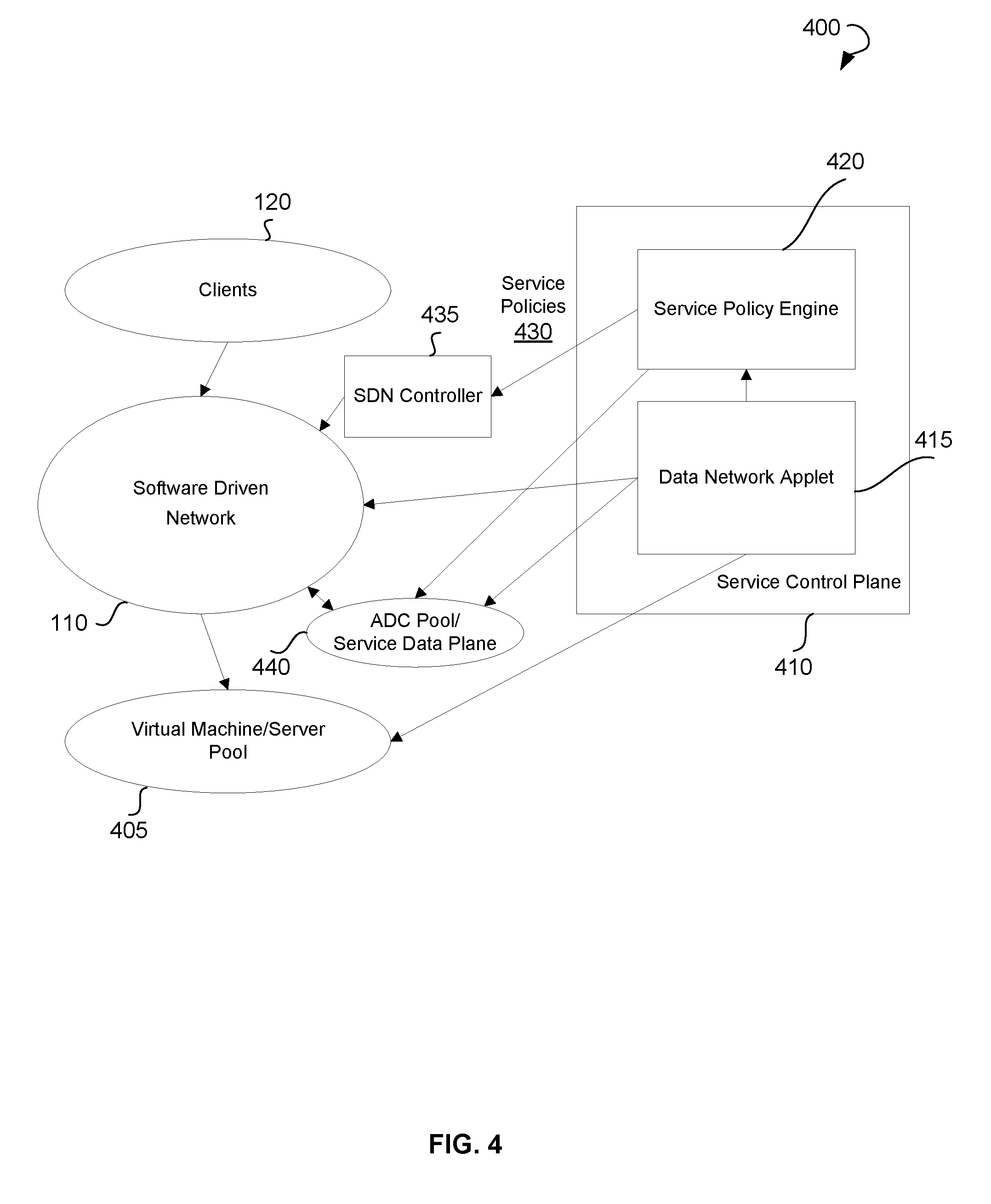
As outlined in the summary, the embodiments of the present disclosure refer to load distribution in an SDN. As referred herein, an SDN is a network that allows managing network services through abstraction of lower level functionality by decoupling a control plane that makes decisions as to where a service request, e.g. traffic from a client to a server, is to be sent from a data plane responsible for forwarding the service request to the selected destination based on the decision of the control plane. The data plane may reside on the network hardware or software devices and the control plane may be executed through the software. Such separation of the planes of the SDN may enable network virtualization, since commands or control rules may be executed by the software. The SDN may be configured to deliver client service requests or host service requests to virtual machines and physical devices, e.g. servers.
The control plane may be configured to ascertain the health and other data associated with the SDN and virtual machines, for example, by real time data network applets. The control plane may leverage the real time data network applets and other means to gauge service responsiveness on the virtual machines, monitor the total connections, central processing unit utilization, and memory as well as network connectivity on the virtual machines and use that information to influence the load distribution decisions and forwarding on the data plane.
Furthermore, the control plane may comprise a service policy engine configured to analyze the collected health data and, based on the analysis, translate the health data into service policies. The service policies may include policies to enhance, i.e. scale out or scale down, the number of virtual machines, traffic classification engines, or backend servers, to remedy or repair failed virtual machines, to secure virtual machines, to introduce new virtual machines, to remove virtual machines, and so forth. Effectively, the service policies may influence load balancing, high availability as well as programming the SDN network. Therefore, based on the service policies, the SDN may scale out or scale down the use of traffic distribution devices through periods or dynamic loads and thereby optimize network resources respectively. The traffic distribution devices may be scaled out or scaled down based, for example, on time of the day. Furthermore, fixed-interval software updates may result in predictable network congestions and the load balancing may need to be scaled out to handle the flash crowd phenomenon and scaled down subsequently. Additionally, the popularity of the service may necessitate the need to scale up the service.
The SDN may comprise a controller enabling programmable control of routing the service requests, such as network traffic, without requiring physical access to network switches. In other words, the controller may be configured to steer the traffic across the network to server pools or virtual machine pools. The service policy engine may communicate with the controller and inject the service policies into the controller. The controller, in turn, may steer traffic across the network devices, such as server or virtual machines, according to the service policies.
In an example embodiment, the service data plane of the SDN may be configured as an application delivery controller (ADC). The control plane may communicate with the ADC by managing a set of service policies mapping service requests to one or more ADCs. The ADC may then relay the service requests to a backend server over a physical or logical network, namely over a server pool or a virtual machine pool.
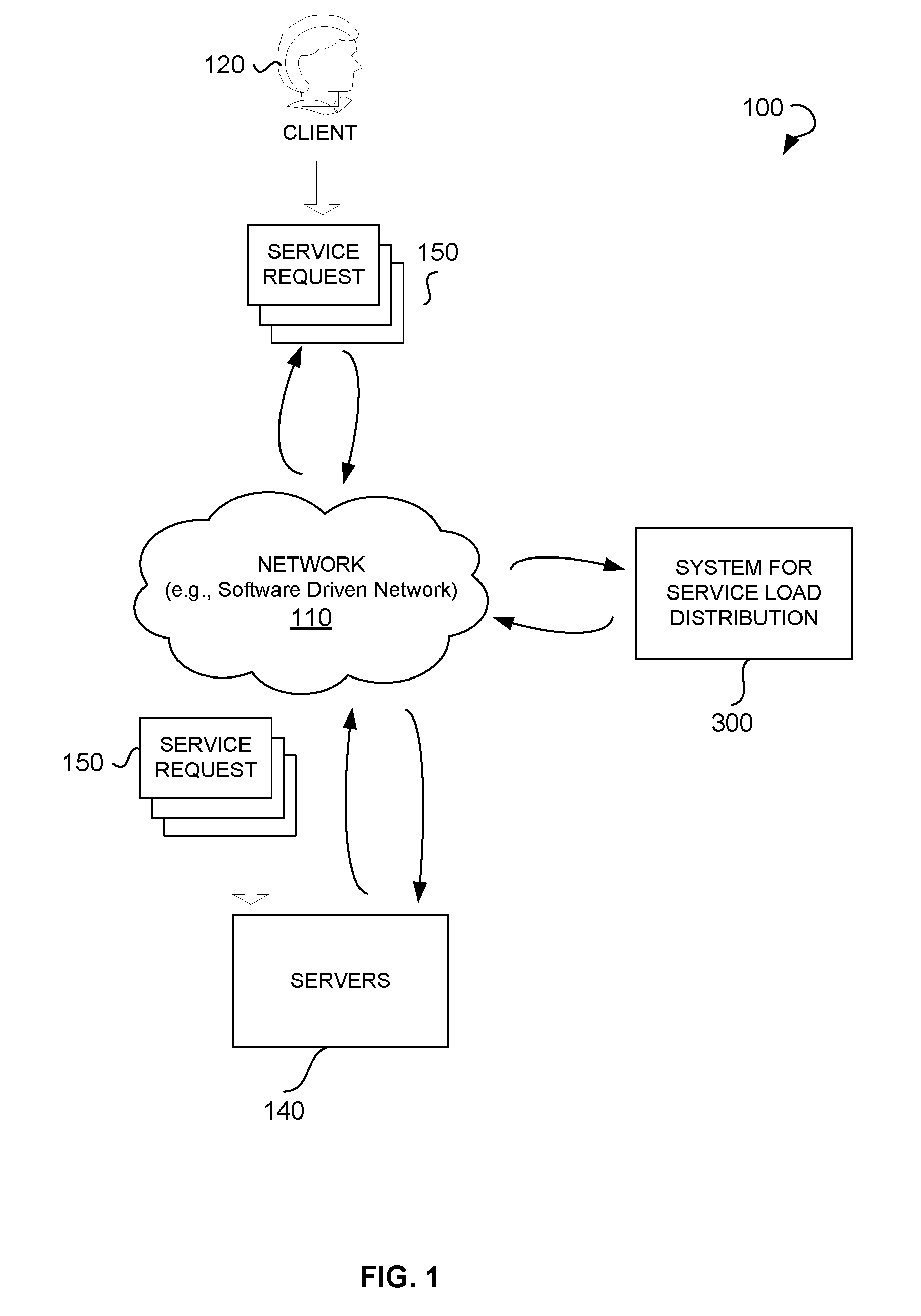
Referring now to the drawings, FIG. 1 illustrates an environment 100 within which a method and a system for load distribution in an SDN can be implemented. The environment 100 may include a network 110, a client 120, a system 300 for load distribution, and servers 140. The client 120 may include a user or a host associated with the network 110.
The network 110 may include the Internet or any other network capable of communicating data between devices. Suitable networks may include or interface with any one or more of, for instance, a local intranet, a PAN (Personal Area Network), a LAN (Local Area Network), a WAN (Wide Area Network), a MAN (Metropolitan Area Network), a virtual private network (VPN), a storage area network (SAN), a frame relay connection, an Advanced Intelligent Network (AIN) connection, a synchronous optical network (SONET) connection, a digital T1, T3, E1 or E3 line, Digital Data Service (DDS) connection, DSL (Digital Subscriber Line) connection, an Ethernet connection, an ISDN (Integrated Services Digital Network) line, a dial-up port such as a V.90, V.34 or V.34bis analog modem connection, a cable modem, an ATM (Asynchronous Transfer Mode) connection, or an FDDI (Fiber Distributed Data Interface) or CDDI (Copper Distributed Data Interface) connection. Furthermore, communications may also include links to any of a variety of wireless networks, including WAP (Wireless Application Protocol), GPRS (General Packet Radio Service), GSM (Global System for Mobile Communication), CDMA (Code Division Multiple Access) or TDMA (Time Division Multiple Access), cellular phone networks, GPS (Global Positioning System), CDPD (cellular digital packet data), RIM (Research in Motion, Limited) duplex paging network, Bluetooth radio, or an IEEE 802.11-based radio frequency network. The network 110 can further include or interface with any one or more of an RS-232 serial connection, an IEEE-1394 (Firewire) connection, a Fiber Channel connection, an IrDA (infrared) port, a SCSI (Small Computer Systems Interface) connection, a USB (Universal Serial Bus) connection or other wired or wireless, digital or analog interface or connection, mesh or Digi.RTM. networking. The network 110 may include a network of data processing nodes that are interconnected for the purpose of data communication. The network 110 may include an SDN. The SDN may include one or more of the above network types. Generally the network 110 may include a number of similar or dissimilar devices connected together by a transport medium enabling communication between the devices by using a predefined protocol. Those skilled in the art will recognize that the present disclosure may be practiced within a variety of network configuration environments and on a variety of computing devices.
As shown in FIG. 1, the client 120 may send service requests 150 to servers 140, which may include backend servers. The service requests 150 may include an HTTP request, a video streaming request, a file download request, a transaction request, a conference request, and so forth. The servers 140 may include a web server, a wireless application server, an interactive television server, and so forth. The system 300 for load distribution may balance flow of the service requests 150 among traffic forwarding devices of the network 110. The system 300 for load distribution may analyze the flow of the service requests 150 and determine which and how many traffic forwarding devices of the network 110 are needed to deliver the service requests 150 to the servers 140.
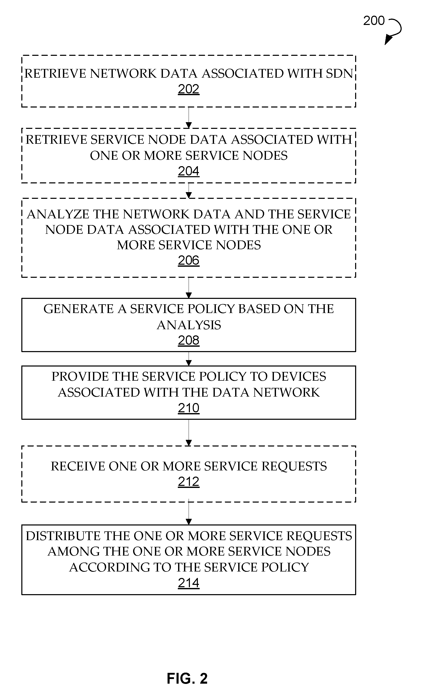
FIG. 2 is a process flow diagram showing a method 200 for service load distribution in an SDN, according to an example embodiment. The method 200 may be performed by processing logic that may comprise hardware (e.g., decision making logic, dedicated logic, programmable logic, and microcode), software (such as software running on a general-purpose computer system or a dedicated machine), or a combination of both.
The method 200 may commence with receiving network data associated with the SDN at operation 202. In an example embodiment, the network data associated with the SDN may be indicative of the health of the SDN, processing unit utilization, number of total connections, memory status, network connectivity, backend server capacity, and so forth. At operation 204, the method may comprise retrieving service node data associated with one or more service nodes. In an example embodiment, the one or more service nodes may include a virtual machine and a physical device. The service node data may be indicative of health of the node, dynamic state, node processing unit utilization, node memory status, network connectivity of the service nodes, responsiveness of the one or more service nodes, and so forth.
At operation 206, the retrieved network data and service node data may be analyzed. Based on the analysis, a service policy may be generated at operation 208. The service policy may include one or more of the following: a service address, a service node address, a traffic distribution policy, a service node load policy, and so forth. The method may further comprise providing, i.e. pushing, the generated service policy to devices associated with the data network. The devices associated with the data network may include the service nodes and traffic classification engines.
The method 200 may continue with providing the generated service policy to the devices associated with the data network at operation 210. Upon receiving one or more service requests at operation 212, the one or more service requests may be distributed among the one or more service nodes according to the service policy at operation 214. In an example embodiment, the method 200 may comprise developing, based on the analysis, a further service policy. The further service policy may be associated with scaling out, scaling down, remedying, removing services associated with the one or more service nodes, introducing a new service associated with the one or more service nodes, and so forth.
In an example embodiment, the method 200 may comprise performing health checks of a backend server by the devices associated with the data network. In further example embodiments, the method 200 may comprise scaling up or scaling down service nodes, backend servers, traffic classification engines, and cluster masters in a graceful manner with minimum to no disruption to the traffic flow. Furthermore, the services may be scaled up or scaled down in a graceful manner with minimum to no disruption to traffic flow. In the event of scaling up or scaling down of the service node, the service requests may be redirected to one or more other service nodes to continue processing data associated with the service request. In further example embodiments, the method 200 may comprise optimizing reverse traffic from backend servers to the service node handling the service.
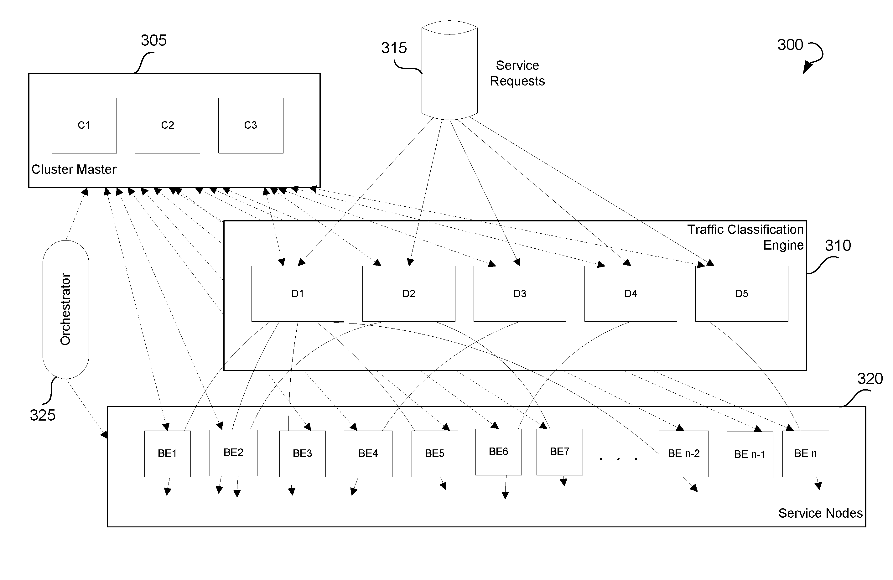
FIG. 3 shows a block diagram illustrating various modules of an exemplary system 300 for service load distribution in an SDN. The system 300 may comprise a cluster of devices eligible as a cluster master. The system 300 may comprise a cluster master 305 elected from these devices. The cluster master 305 may be configured to keep track of the SDN and retrieve network data associated with the SDN. In an example embodiment, the network data may include one or more of the following: a number of total connections, processing unit utilization, a memory status, a network connectivity, backend server capacity, and so forth. Furthermore, the cluster master 305 may be configured to keep track of the service nodes and retrieve service node data associated with one or more service nodes. The service node data may include one or more of the following: health, dynamic state, responsiveness of the one or more service nodes, and so forth. In other words, the cluster master 305 may keep track of the health of the network and each service node associated with the system 300. The cluster master 305 may analyze the retrieved network data and service node data. Based on the analysis, the cluster master 305 may generate a service policy. The service policy may include a service address, a service node address, a service node load policy, a traffic distribution policy also referred to as a traffic mapping, and so forth. The cluster master 305 may provide the generated service policy to the devices associated with the data network, such as service nodes and traffic classification engines.
In an example embodiment, the cluster master 305 may be further configured to develop, based on the analysis, a further service policy. The further policy may be associated with scaling out, scaling down, remedying, removing devices, such as service nodes, traffic classification engines, backend servers and so forth, introducing new service nodes, traffic classification engines, backend servers, and so forth.
In an example embodiment, the cluster master 305 may be further configured to facilitate an application programmable interface (not shown) for a network administrator to enable the network administrator to develop, based on the analysis, a further service policy using the retrieved network data and service node data and analytics. This approach may allow application developers to write directly to the network without having to manage or understand all the underlying complexities and subsystems that compose the network.
In a further example embodiment, the cluster master 305 may include a backup unit (not shown) configured to replace the cluster master in case of a failure of the cluster master 305.
The system 300 may comprise a traffic classification engine 310. The traffic classification engine 310 may be implemented as one or more software modules, hardware modules, or a combination of hardware and software. The traffic classification engine 310 may include an engine configured to monitor data flows and classify the data flows based on one or more attributes associated with the data flows, e.g. uniform resource locators (URLs), IP addresses, port numbers, and so forth. Each resulting data flow class can be specifically designed to implement a certain service for a client. In an example embodiment, the cluster master 305 may send a service policy to the traffic classification engine 310. The traffic classification engine 310 may be configured to receive the service policy from the cluster master 305. Furthermore, the traffic classification engine 310 may be configured to receive one or more (incoming) service requests 315, e.g. incoming data traffic from routers or switches (not shown). Typically, the data traffic may be distributed from the routers or switches to each of the traffic classification engines 310 evenly. In an example embodiment, a router may perform a simple equal-cost multi-path (ECMP) routing to distribute the traffic equally to all the traffic classification engines 310. The traffic classification engines 310 may distribute the one or more service requests among one or more service nodes 320 according to the service policy. The traffic may be distributed to the one or more service nodes 320 in an asymmetric fashion. The traffic to the service nodes 320 may be direct or through a tunnel (IP-in-IP or other overlay techniques). The traffic classification engine 310 may be stateless or stateful, may act on a per packet basis, and direct each packet of the traffic to the corresponding service node 320. When there is a change in the service nodes state, the cluster master 305 may send a new service policy, such as a new traffic map, to the traffic classification engine 310.
The system 300 may comprise the one or more service nodes 320. The one or more service nodes 320 may include a virtual machine or a physical device that may serve a corresponding virtual service to which the traffic is directed. The cluster master 305 may send the service policy to the service nodes 320. The service nodes 320 may be configured to receive the service policy from the cluster master 305. Furthermore, the service nodes 320 may receive, based on the service policy, the one or more service requests 315 from the traffic classification engine 310. The one or more service nodes 320 may process the received one or more service requests 315 according to the service policy. The processing of the one or more service requests 315 may include forwarding the one or more service requests 315 to one or more backend destination servers (not shown). Each service node 320 may serve one or more virtual services. The service nodes 320 may be configured to send the service node data to the cluster master 305.
According to further example embodiment, an existing service node may redirect packets for existing flows to another service node if it is the new owner of the flow based on the redistribution of flows to the service nodes. In addition, a service node taking over the flow may redirect packets to the service node that was the old owner for the flows under consideration, for cases where the flow state needs to be pinned down to the old owner to maintain continuity of service.
Furthermore, in an example embodiment, the cluster master 305 may perform a periodic health check on the service nodes 320 and update the service nodes 320 with a service policy, such as a traffic map. When there is a change in the traffic assignment and a packet of the data traffic in a flow reaches a service node 320, the service node 320 may redirect the packet to another service node. Redirection may be direct or through a tunnel (e.g. IP-in-IP or other overlay techniques).
It should be noted that if each of the devices of the cluster in the network performs the backend server health check, it may lead to a large number of health check packets sent to an individual device. In view of this, the backend server health check may be performed by a few devices of the cluster and the result may be shared among the rest of the devices in the cluster. The health check may include a service check and a connectivity check. The service check may include determining whether the application or the backend server is still available. As already mentioned above, not every device in the cluster needs to perform this check. The check may be performed by a few devices and the result propagated to the rest of the devices in the cluster. A connectivity check includes determining whether the service node can reach the backend server. The path to the backend server may be specific to the service node, so this may not be distributed across service nodes, and each device in the cluster may perform its own check.
In an example embodiment, the system 300 may comprise an orchestrator 325. The orchestrator 325 may be configured to bring up and bring down the service nodes 320, the traffic classification engines 310, and backend servers. The orchestrator 325 may detect presence of the one or more service nodes 320 and transmit data associated with the presence of the one or more service nodes 320 to the cluster master 305. Furthermore, the orchestrator 325 may inform the cluster master 305 of bringing up or bringing down the service nodes 320. The orchestrator 325 may communicate with the cluster master 305 and the service nodes 320 using one or more Application Programming Interfaces (APIs).
In an example embodiment, a centralized or distributed network database may be used and shared among all devices in the cluster of the system 300, such as the cluster master, the traffic classification engine, and other service nodes. Each device may connect to the network database and update tables according to its role. Relevant database records may be replicated to the devices that are part of the cluster. The distributed network database may be used to store configurations and states of the devices, e.g. to store data associated with the cluster master, the traffic classification engine, the one or more service nodes, backend servers, and service policy data. The data stored in the distributed network database may include the network data and the service node data. The distributed network database may include tables with information concerning service types, availability of resources, traffic classification, network maps, and so forth. The cluster master 305 may be responsible for maintaining the distributed network database and replicating it to devices. The network database may be replicated to the traffic classification engines 310 and the service nodes 320. In an example embodiment, the network database may internally replicate data across the participant nodes.
In the embodiments described above, the system 300 may comprise a dedicated cluster master 305, dedicated traffic classification engines 310, and dedicated service nodes 320. In other words, specific devices may be responsible for acting as the cluster master, the traffic classification engine, and the service node. In further example embodiments, the system 300 may include no dedicated devices acting as a cluster master. In this case, the cluster master functionality may be provided by either the traffic classification engines or by the service nodes. Thus, one of the traffic classification engines or one of the service nodes may act as the cluster master. In case the traffic classification engine or service node acting as the cluster master fails, another traffic classification engine or service node may be elected as the cluster master. The traffic classification engines and the service nodes not elected as the cluster master may be configured as backup cluster masters and synchronized with the current cluster master. In an example embodiment, the cluster master may consist of multiple active devices which can act as a single master by sharing duties among the devices.
In further example embodiments, the system 300 may comprise a dedicated cluster master with no dedicated devices acting as traffic classification engines. In this case, the traffic classification may be performed by one of upstream routers or switches. Also, the service nodes may distribute the traffic among themselves. In an example embodiment, the cluster master and the service nodes may be configured to act as a traffic classification engine.
In further example embodiments, the system 300 may include no devices acting as cluster masters and traffic classification engines. In this case, one of the service nodes may also act as the cluster master. The traffic classification may be done by upstream routers or switches. The cluster master may program the upstream routers with the traffic mapping. Additionally, the service nodes may distribute the traffic among themselves.
It should be noted that bringing up new service nodes when the load increases and bringing down the service nodes when the load becomes normal may be performed gracefully, without affecting existing data traffic and connections. When the service node comes up, the distribution of traffic may change from distribution to n service nodes to distribution to (n+1) service nodes.
When a service node is about to be brought down, the traffic coming to this service node may be redirected to other service nodes. For this purpose, a redirection policy associated with the service node about to be brought down may be created by the cluster master and sent to the traffic distribution engine and/or the service nodes. Upon receiving the redirection policy, the traffic distribution engine may direct the traffic to another service node.
In an example embodiment, the system 300 may comprise, for example, a plurality of traffic distribution engines, each of which may serve traffic to multiple services. Each of the traffic distribution engines may communicate with a different set of service nodes. In case one of the traffic distribution engines fails, another traffic distribution engines may be configured to substitute the failed traffic distribution engine and to distribute the traffic of the failed traffic distribution engines to the corresponding service nodes. Therefore, each of the traffic distribution engines may comprise addresses of all service nodes and not only addresses associated with the service nodes currently in communication with the traffic distribution engine.
FIG. 4 shows a diagram 400 for load distribution of an SDN. As shown, diagram 400 includes clients 120, e.g., a computer connected to a network 110. The network 110 may include the SDN. The clients 120 may send one or more service requests for services provided by one or more servers of the virtual machine/server pool 405 (also referred to herein as virtual machine/physical server pool 405). These servers may include web servers, wireless application servers, interactive television servers, and so forth. These service requests can be load balanced by a system for load distribution described above. In other words, the service requests of the client 120 may be intelligently distributed among virtual machine/physical server pool 405 of the SDN.
The system for load distribution may include a service control plane 410. The service control plane 410 may include one or more data network applets 415, for example, a real time data network applet. The data network applets 415 may check the health and other data associated with the SDN and the virtual machines in the virtual machine/server pool 405. For example, the data network applets 415 may determine responsiveness of the virtual machines in the virtual machine/server pool 405. Furthermore, the data network applets 415 may monitor the total connections, central processing unit utilization, memory, network connectivity on the virtual machines in the virtual machine/server pool 405, and so forth. Therefore, the data network applets 415 may retrieve fine-grained, comprehensive information concerning the SDN and virtual machine service infrastructure.
The retrieved health data may be transmitted to a service policy engine 420. In example embodiments, a cluster master 305 described above may act as the service policy engine 420. The service policy engine 420 may analyze the health data and, upon the analysis, generate a set of service policies 430 to scale up/down the services, to secure services, to introduce new services, to remove services, to remedy or repair failed devices, and so forth. The system for load distribution may further comprise an orchestrator (not shown) configured to bring up more virtual machines on demand. Therefore, in order to deliver a smooth client experience, the service requests may be load balanced across the virtual machines in the virtual machine/server pool 405.
Furthermore, the service policies 430 may be provided to an SDN controller 435. The SDN controller 435, in turn, may steer service requests, i.e. data traffic, across the network devices in the SDN. Effectively, these policies may influence load balancing, high availability as well as programming the SDN network to scale up or scale down services.
Generally speaking, by unlocking the data associated with the network, service nodes and the server/virtual machines from inside the network, transforming the data into relevant information and the service policies 430, and then presenting the service policies 430 to the SDN controller 435 for configuring the SDN 110, the described infrastructure may enable feedback loops between underlying infrastructure and applications to improve network optimization and application responsiveness.
The service control plane 410 working in conjunction with the SDN controller 435 and the service policy engine 420 may create a number of deployment possibilities, which may offer an array of basic and advanced load distribution features. In particular, to provide a simple load balancing functionality, the SDN controller 435 and the service control plane 410 may provide some load balancing of their own by leveraging the capabilities of the SDN 110 or, alternatively, work in conjunction with an ADC 440, also referred to as a service data plane included in the SDN 110 to optionally provide advanced additional functionality.
In an example embodiment, when the service control plane 410 may be standalone, i.e. without an ADC 440, virtual machines in the virtual machine/server pool 405, when scaled up, may be programmed with a virtual Internet Protocol (VIP) address on a loopback interface of the virtual machines in the virtual machine/server pool 405. Thus, for data traffic in need of simple service fulfillment, the service control plane 410 may establish simple policies for distributing service requests and instruct the SDN controller 435 to program network devices to distribute the service requests directly to different virtual machines/physical servers in the virtual machine/server pool 405. This step may be performed over a physical or logical network.
In an example embodiment, when the service control plane 410 may work in cooperation with an ADC 440, for more sophisticated ADC functionality typically offered by a purpose built ADC device, the service control plane 410 may manage a set of service policy mapping service requests to one or more ADC devices. The service control plane 410 may instruct the SDN controller 435 to program network devices such that the service requests, i.e. the traffic, may reach one or more ADCs 440. The ADC 440 then may relay the service request to a backend server over a physical or logical network.
In the described embodiment several traffic flow scenarios may exist. In an example embodiment, only forward traffic may go through the ADC 440. If a simple functionality of the ADC 440, e.g. rate limiting, bandwidth limiting, scripting policies, is required, the forward traffic may traverse the ADC 440. The loopback interface on the servers may be programmed with the VIP address. Response traffic from the virtual machines in the virtual machine/server pool 405 may bypass the ADC 440.
In a further example embodiment, forward and reverse traffic may traverse the ADC 440. In the ADC 440 providing a more advanced functionality, e.g. transmission control protocol (TCP) flow optimization, secure sockets layer (SSL) decryption, compression, caching and so forth, is required, the service control plane 410 may need to ensure both the forward and reverse traffic traverses through the ADC 440 by appropriately programming the SDN 110.
FIG. 5 shows a diagrammatic representation of a machine in the example electronic form of a computer system 500, within which a set of instructions for causing the machine to perform any one or more of the methodologies discussed herein may be executed. In various example embodiments, the machine operates as a standalone device or may be connected (e.g., networked) to other machines. In a networked deployment, the machine may operate in the capacity of a server or a client machine in a server-client network environment, or as a peer machine in a peer-to-peer (or distributed) network environment. The machine may be a PC, a tablet PC, a set-top box (STB), a cellular telephone, a portable music player (e.g., a portable hard drive audio device such as an Moving Picture Experts Group Audio Layer 3 (MP3) player), a web appliance, a network router, switch or bridge, or any machine capable of executing a set of instructions (sequential or otherwise) that specify actions to be taken by that machine. Further, while only a single machine is illustrated, the term "machine" shall also be taken to include any collection of machines that individually or jointly execute a set (or multiple sets) of instructions to perform any one or more of the methodologies discussed herein.
The example computer system 500 includes a processor or multiple processors 502 (e.g., a central processing unit (CPU), a graphics processing unit (GPU), or both), a main memory 504 and a static memory 506, which communicate with each other via a bus 508. The computer system 500 may further include a video display unit 510 (e.g., a liquid crystal display (LCD) or a cathode ray tube (CRT)). The computer system 500 may also include an alphanumeric input device 512 (e.g., a keyboard), a cursor control device 514 (e.g., a mouse), a disk drive unit 516, a signal generation device 518 (e.g., a speaker), and a network interface device 520.
The disk drive unit 516 includes a non-transitory computer-readable medium 522, on which is stored one or more sets of instructions and data structures (e.g., instructions 524) embodying or utilized by any one or more of the methodologies or functions described herein. The instructions 524 may also reside, completely or at least partially, within the main memory 504 and/or within the processors 502 during execution thereof by the computer system 500. The main memory 504 and the processors 502 may also constitute machine-readable media.
The instructions 524 may further be transmitted or received over a network 526 via the network interface device 520 utilizing any one of a number of well-known transfer protocols (e.g., Hyper Text Transfer Protocol (HTTP)).
While the computer-readable medium 522 is shown in an example embodiment to be a single medium, the term "computer-readable medium" should be taken to include a single medium or multiple media (e.g., a centralized or distributed database and/or associated caches and servers) that store the one or more sets of instructions. The term "computer-readable medium" shall also be taken to include any medium that is capable of storing, encoding, or carrying a set of instructions for execution by the machine and that causes the machine to perform any one or more of the methodologies of the present application, or that is capable of storing, encoding, or carrying data structures utilized by or associated with such a set of instructions. The term "computer-readable medium" shall accordingly be taken to include, but not be limited to, solid-state memories, optical and magnetic media, and carrier wave signals. Such media may also include, without limitation, hard disks, floppy disks, flash memory cards, digital video disks, random access memory (RAMs), read only memory (ROMs), and the like.
The example embodiments described herein can be implemented in an operating environment comprising computer-executable instructions (e.g., software) installed on a computer, in hardware, or in a combination of software and hardware. The computer-executable instructions can be written in a computer programming language or can be embodied in firmware logic. If written in a programming language conforming to a recognized standard, such instructions can be executed on a variety of hardware platforms and for interfaces to a variety of operating systems. Although not limited thereto, computer software programs for implementing the present method can be written in any number of suitable programming languages such as, for example, Hypertext Markup Language (HTML), Dynamic HTML, Extensible Markup Language (XML), Extensible Stylesheet Language (XSL), Document Style Semantics and Specification Language (DSSSL), Cascading Style Sheets (CSS), Synchronized Multimedia Integration Language (SMIL), Wireless Markup Language (WML), Java.TM., Jini.TM., C, C++, Perl, UNIX Shell, Visual Basic or Visual Basic Script, Virtual Reality Markup Language (VRML), ColdFusion.TM. or other compilers, assemblers, interpreters or other computer languages or platforms.
Thus, methods and systems for load distribution in an SDN are disclosed. Although embodiments have been described with reference to specific example embodiments, it will be evident that various modifications and changes can be made to these example embodiments without departing from the broader spirit and scope of the present application. Accordingly, the specification and drawings are to be regarded in an illustrative rather than a restrictive sense.
* * * * *
References
D00000
D00001
D00002
D00003
D00004
D00005
XML
uspto.report is an independent third-party trademark research tool that is not affiliated, endorsed, or sponsored by the United States Patent and Trademark Office (USPTO) or any other governmental organization. The information provided by uspto.report is based on publicly available data at the time of writing and is intended for informational purposes only.
While we strive to provide accurate and up-to-date information, we do not guarantee the accuracy, completeness, reliability, or suitability of the information displayed on this site. The use of this site is at your own risk. Any reliance you place on such information is therefore strictly at your own risk.
All official trademark data, including owner information, should be verified by visiting the official USPTO website at www.uspto.gov. This site is not intended to replace professional legal advice and should not be used as a substitute for consulting with a legal professional who is knowledgeable about trademark law.