Imaging lens and image capturing device
Matsumoto Nov
U.S. patent number 10,488,633 [Application Number 15/632,312] was granted by the patent office on 2019-11-26 for imaging lens and image capturing device. This patent grant is currently assigned to Nikon Corporation. The grantee listed for this patent is Nikon Corporation. Invention is credited to Miho Matsumoto.


View All Diagrams
| United States Patent | 10,488,633 |
| Matsumoto | November 26, 2019 |
Imaging lens and image capturing device
Abstract
An imaging lens (PL) has an image surface (I) curved to have a concave surface facing an object and comprises, in order from the object along the optical axis (Ax): a first lens (L1) having positive refractive power; a second lens (L2) having negative refractive power; a third lens (L3) having positive refractive power; a fourth lens (L4) having positive or negative refractive power; and a fifth lens (L5) having at least one lens surface formed as an aspherical surface and having negative refractive power. The following conditional expression is satisfied: 0.005<f/|f4|<0.5 where, f denotes a focal length of the imaging lens (PL), and f4 denotes a focal length of the fourth lens (L4).
| Inventors: | Matsumoto; Miho (Tokyo, JP) | ||||||||||
|---|---|---|---|---|---|---|---|---|---|---|---|
| Applicant: |
|
||||||||||
| Assignee: | Nikon Corporation (Tokyo,
JP) |
||||||||||
| Family ID: | 56355618 | ||||||||||
| Appl. No.: | 15/632,312 | ||||||||||
| Filed: | June 24, 2017 |
Prior Publication Data
| Document Identifier | Publication Date | |
|---|---|---|
| US 20170293116 A1 | Oct 12, 2017 | |
Related U.S. Patent Documents
| Application Number | Filing Date | Patent Number | Issue Date | ||
|---|---|---|---|---|---|
| PCT/JP2015/000090 | Jan 9, 2015 | ||||
| Current U.S. Class: | 1/1 |
| Current CPC Class: | H04N 5/3572 (20130101); G02B 5/126 (20130101); G02B 13/02 (20130101); G02B 13/18 (20130101); G02B 13/0045 (20130101); H04N 5/232 (20130101); G02B 13/0015 (20130101) |
| Current International Class: | G02B 9/60 (20060101); G02B 5/126 (20060101); G02B 13/00 (20060101); G02B 13/18 (20060101); G02B 13/02 (20060101); H04N 5/232 (20060101) |
References Cited [Referenced By]
U.S. Patent Documents
| 4458991 | July 1984 | Yamada |
| 4699477 | October 1987 | Clarke |
| 4832472 | May 1989 | Robb |
| 5418647 | May 1995 | Ishisaka |
| 5850312 | December 1998 | Kato et al. |
| 6088172 | July 2000 | Sato |
| 6529336 | March 2003 | Kreitzer |
| 7864454 | January 2011 | Tang |
| 9453986 | September 2016 | Ishihara |
| 9496301 | November 2016 | Baba |
| 9557528 | January 2017 | Sano |
| 2003/0142412 | July 2003 | Shirasuna |
| 2007/0236811 | October 2007 | Mori |
| 2012/0162769 | June 2012 | Suzuki et al. |
| 2013/0321932 | December 2013 | Hsu et al. |
| 2014/0029116 | January 2014 | Tsai et al. |
| 2014/0104707 | April 2014 | Nakamura et al. |
| 2014/0139711 | May 2014 | Sano |
| 2015/0077619 | March 2015 | Yamano |
| 2015/0358516 | December 2015 | Baba |
| 2018/0045921 | February 2018 | Kumazawa et al. |
| 57-135911 | Aug 1982 | JP | |||
| 58-46312 | Mar 1983 | JP | |||
| 63-292106 | Nov 1988 | JP | |||
| 05-188292 | Jul 1993 | JP | |||
| 07-120677 | May 1995 | JP | |||
| 11-153752 | Jun 1999 | JP | |||
| 2000-66095 | Mar 2000 | JP | |||
| 2001-356266 | Dec 2001 | JP | |||
| 2004-312239 | Nov 2004 | JP | |||
| 2006-184783 | Jul 2006 | JP | |||
| 2007-279282 | Oct 2007 | JP | |||
| 2007-298572 | Nov 2007 | JP | |||
| 2010-008562 | Jan 2010 | JP | |||
| 2012-141423 | Jul 2012 | JP | |||
| 2012-230233 | Nov 2012 | JP | |||
| 2012-237966 | Dec 2012 | JP | |||
| 2012-252193 | Dec 2012 | JP | |||
| 2013-024892 | Feb 2013 | JP | |||
| 2013-025202 | Feb 2013 | JP | |||
| 2013-061476 | Apr 2013 | JP | |||
| 2013-210534 | Oct 2013 | JP | |||
| 2013-210538 | Oct 2013 | JP | |||
| 2013-210543 | Oct 2013 | JP | |||
| 2013-210549 | Oct 2013 | JP | |||
| 2013-228570 | Nov 2013 | JP | |||
| 5341265 | Nov 2013 | JP | |||
| 2014-178624 | Sep 2014 | JP | |||
| 2014-211586 | Nov 2014 | JP | |||
| 5644947 | Dec 2014 | JP | |||
| 2015-001644 | Jan 2015 | JP | |||
| 2015-022152 | Feb 2015 | JP | |||
| WO 2013/008862 | Jan 2013 | WO | |||
| WO 2013/015082 | Jan 2013 | WO | |||
| WO 2013/027641 | Feb 2013 | WO | |||
| WO 2014/119402 | Aug 2014 | WO | |||
Other References
|
English Translation of International Search Report from International Patent Application No. PCT/JP2015/000090, dated Mar. 31, 2015. cited by applicant . English Translation of Written Opinion of the International Searching Authority from International Patent Application No. PCT/JP2015/000090, dated Mar. 31, 2015. cited by applicant . Office Action from Japanese Patent Application No. 2016-568167, dated Sep. 25, 2018. cited by applicant . International Search Report from International Patent Application No. PCT/JP2015/002313, dated Aug. 4, 2015. cited by applicant. |
Primary Examiner: Martinez; Joseph P
Attorney, Agent or Firm: Shapiro, Gabor and Rosenberger, PLLC
Parent Case Text
RELATED APPLICATIONS
This is a continuation of PCT International Application No. PCT/JP2015/000090, filed on Jan. 9, 2015, which is hereby incorporated by reference.
Claims
The invention claimed is:
1. An imaging lens having an image surface curved to have a concave surface facing an object, the imaging lens comprising, in order from the object: a first lens having positive refractive power; a second lens having negative refractive power; a third lens having positive refractive power; a fourth lens having positive or negative refractive power; and a fifth lens having at least one lens surface formed as an aspherical surface and having negative refractive power, wherein the following conditional expression are satisfied: 0.005<f/|f4|<0.5 -0.4<f/f5<-0.1, where f denotes a focal length of the imaging lens, f4 denotes a focal length of the fourth lens, and f5 denotes a focal length of the fifth lens.
2. The imaging lens according to claim 1, wherein the following conditional expression is satisfied: 0.03<f/f3<0.25, where f3 denotes a focal length of the third lens.
3. The imaging lens according to claim 2, wherein the following conditional expression is satisfied: 0.72<f/f12<0.83, where f12 denotes a combined focal length of the first lens and the second lens.
4. The imaging lens according to claim 1, wherein the following conditional expression is satisfied: -0.09<SAG/f12<-0.02, where SAG denotes an amount of curvature of the image surface along an optical axis at a maximum image height, when taking a direction of the optical axis from the object to the image surface as a positive direction, and f12 denotes the combined focal length of the first lens and the second lens.
5. The imaging lens according to claim 1, wherein the following conditional expression is satisfied: 0<(ra+rb)/(ra-rb)<0.8, where ra denotes a radius of curvature of an object-side lens surface of the second lens, and rb denotes a radius of curvature of an image-side lens surface of the second lens.
6. The imaging lens according to claim 1, wherein the following conditional expression is satisfied: |tb5-ta5|/ta5<0.4, where ta5 denotes a thickness of the fifth lens in an optical axis direction at a position on the optical axis, and tb5 denotes a thickness of the fifth lens in the optical axis direction at a position where a principal ray is incident on an object-side lens surface of the fifth lens at a maximum angle of view.
7. The imaging lens according to claim 1, wherein the following conditional expression is satisfied: 0.2<|tb4-ta4|/ta4<2, where ta4 denotes a thickness of the fourth lens in an optical axis direction at a position on the optical axis, tb4 denotes a thickness of the fourth lens in the optical axis direction at a position where a principal ray is incident on an object-side lens surface of the fourth lens at a maximum angle of view.
8. The imaging lens according to claim 1, wherein the following conditional expression is satisfied: |tb3-ta3|/ta3<0.1, where ta3 denotes a thickness of the third lens in an optical axis direction at a position on the optical axis, and tb3 denotes a thickness of the third lens in the optical axis direction at a position where a principal ray is incident on an object-side lens surface of the third lens at a maximum angle of view.
9. The imaging lens according to claim 1, wherein a bonded-multilayer diffractive optical element is provided on at least one lens surface of the first lens, the second lens, the third lens, the fourth lens, and the fifth lens.
10. An image capturing device, comprising: an imaging lens according to claim 1; and an image sensor having an imaging surface coincident with the image surface of the imaging lens in a focused state of the imaging lens.
Description
TECHNICAL FIELD
The present invention relates to an imaging lens usable for an image capturing device embedded in a mobile terminal or the like.
TECHNICAL BACKGROUND
Imaging lenses (see, for example, Patent Document 1) used in small image capturing devices embedded in mobile terminals or the like are required to have high resolving power of about 1 to 2 .mu.m on an imaging surface, due to development of image sensors with increased pixels. The imaging lenses are also required to have a shorter entire length due to ever increasing demand for thinner mobile terminals or the like. The high resolving power may be achieved by an imaging lens having an aspherical lens surface. Thus, almost all the lens surfaces of conventional imaging lenses used in small image capturing devices are aspherical. Another possible solution is to increase the number of lens to achieve the imaging lens with high resolving power. Logically, the increased number of lenses simply leads to a larger space required for the lenses to be inserted, and thus results in a longer length of the entire imaging lens.
PRIOR ARTS LIST
Patent Document
Patent Document 1: WO2013/027641(A1)
SUMMARY
An imaging lens has an image surface curved to have a concave surface facing an object and comprises, in order from the object: a first lens having positive refractive power; a second lens having negative refractive power; a third lens having positive refractive power; a fourth lens having positive or negative refractive power; and a fifth lens having at least one lens surface formed as an aspherical surface and having negative refractive power. The following conditional expression is satisfied. 0.005<f/|f4|<0.5
where, f denotes a focal length of the imaging lens, and
f4 denotes a focal length of the fourth lens.
An image capturing device comprises: an imaging lens with which an image of an object is formed on an imaging surface; and an image sensor configured to obtain the image of the object formed on the imaging surface. The imaging surface is curved to have a concave surface facing an object. The imaging lens has an image surface curved along the imaging surface. The imaging lens is the above-described imaging lens.
BRIEF DESCRIPTION OF THE DRAWINGS
FIG. 1 is a diagram illustrating a lens configuration of an imaging lens according to Example 1.
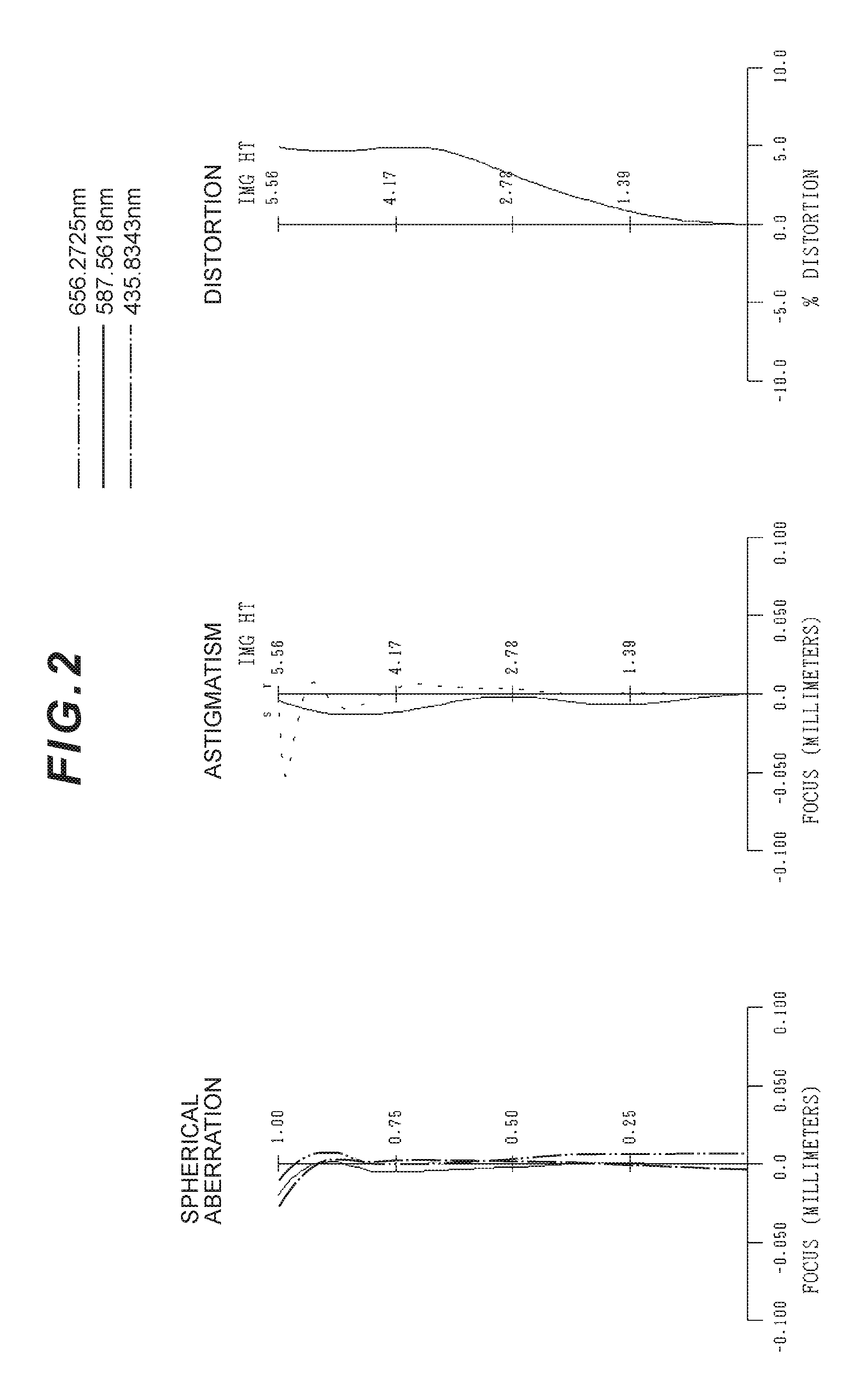
FIG. 2 is graphs illustrating longitudinal aberrations of the imaging lens according to Example 1.
FIG. 3 is graphs illustrating lateral aberrations of the imaging lens according to Example 1.
FIG. 4 is a diagram illustrating a lens configuration of an imaging lens according to Example 2.
FIG. 5 is graphs illustrating longitudinal aberrations of the imaging lens according to Example 2.
FIG. 6 is graphs illustrating lateral aberrations of the imaging lens according to Example 2.
FIG. 7 is a diagram illustrating a lens configuration of an imaging lens according to Example 3.
FIG. 8 is graphs illustrating longitudinal aberrations of the imaging lens according to Example 3.
FIG. 9 is graphs illustrating lateral aberrations of the imaging lens according to Example 3.
FIG. 10 is a diagram illustrating a lens configuration of an imaging lens according to Example 4.
FIG. 11 is graphs illustrating longitudinal aberrations of the imaging lens according to Example 4.
FIG. 12 is graphs illustrating lateral aberrations of the imaging lens according to Example 4.
FIG. 13 is a diagram illustrating a lens configuration of an imaging lens according to Example 5.
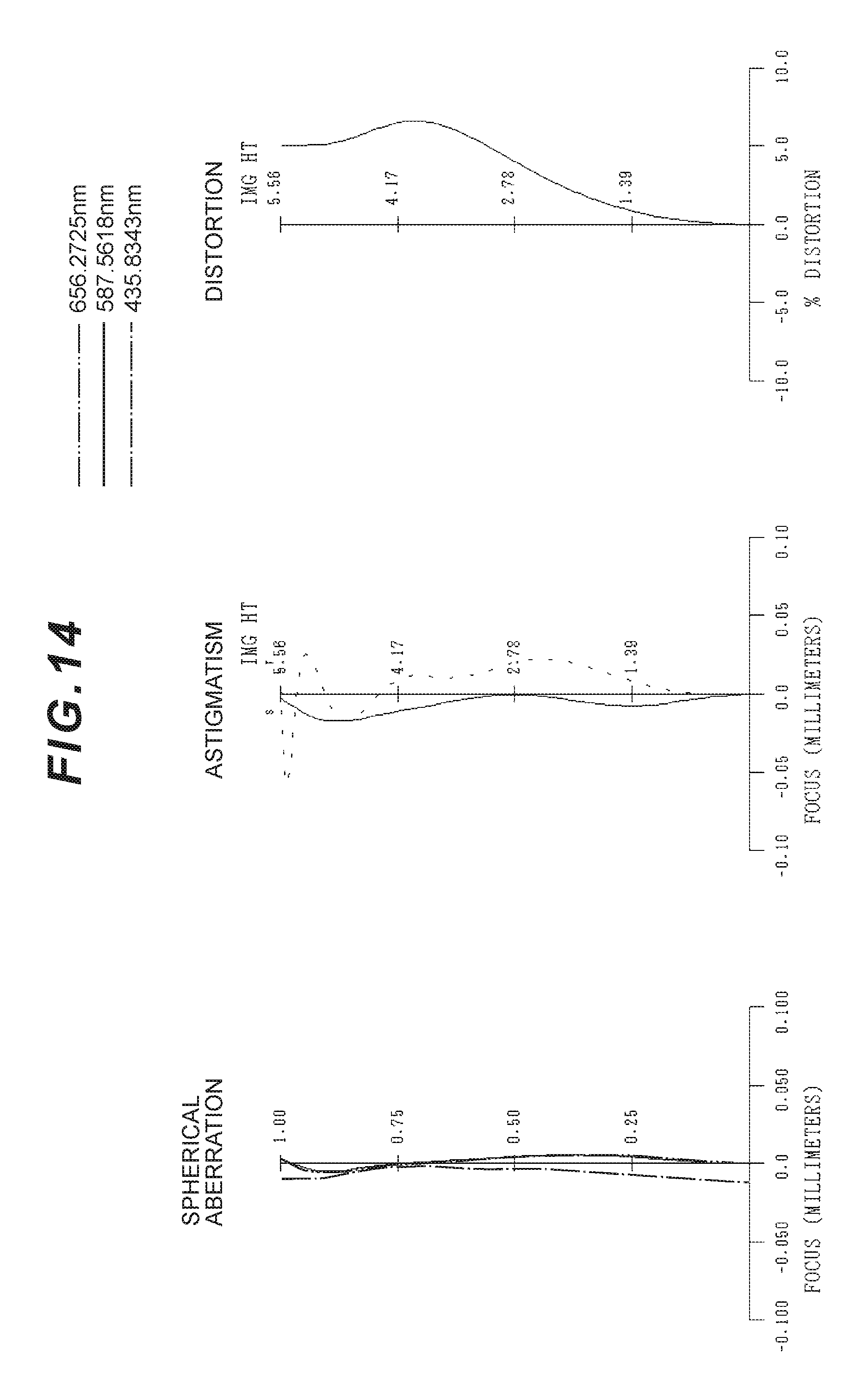
FIG. 14 is graphs illustrating longitudinal aberrations of the imaging lens according to Example 5.
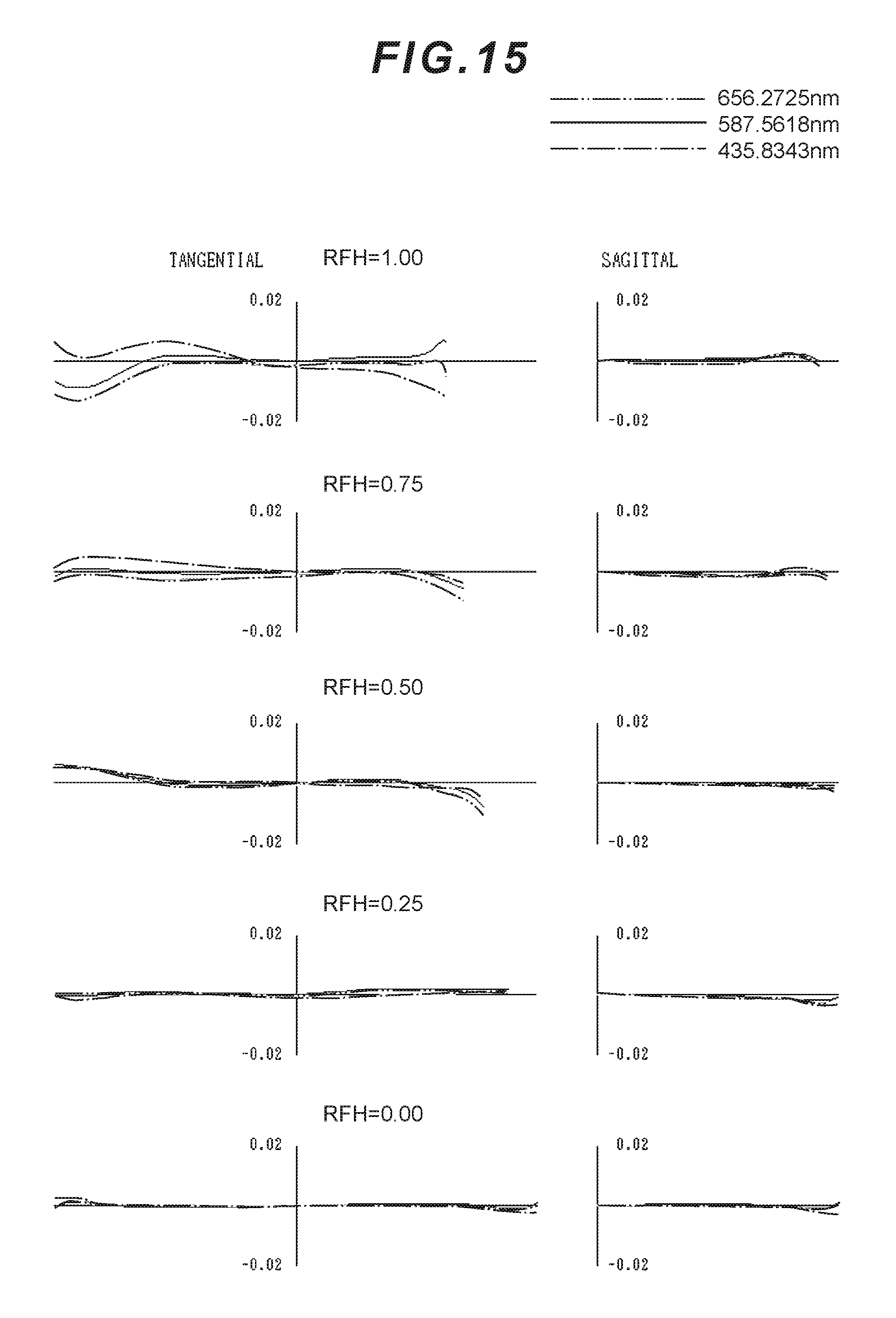
FIG. 15 is graphs illustrating lateral aberrations of the imaging lens according to Example 5.
FIG. 16 is a cross-sectional view of an image capturing device.
FIG. 17 is an enlarged view of a part of the imaging lens.
DESCRIPTION OF THE EMBODIMENTS
Preferred embodiments of the present application are described below with reference to the drawings. FIG. 16 illustrates an image capturing device CMR including an imaging lens according to the present application. Specifically, FIG. 16 is a cross-sectional view of the image capturing device CMR embedded in a mobile terminal or the like. The image capturing device CMR mainly includes: a barrel BR provided in a device main body BD of the mobile terminal or the like; an imaging lens PL contained and held in the barrel BR; an image sensor SR contained in the barrel BR; and a control unit PU contained in the device main body BD. With the imaging lens PL, an image of a subject (object) is formed on an imaging surface of the image sensor SR.
The image sensor SR includes an image sensor such as a CCD or a CMOS, and is disposed along an image surface I of the imaging lens PL. The image sensor SR has a surface as an imaging surface on which pixels (photoelectric conversion elements) are two-dimensionally formed. The imaging surface of the image sensor SR is curved to have a concave surface facing the object. The imaging lens PL has the image surface I curved along the imaging surface of the image sensor SR. For example, the image sensor SR has the imaging surface as a spherical concave surface or an aspherical concave surface. The image sensor SR photoelectrically converts light from the subject, focused on the imaging surface with the imaging lens PL, and outputs the resultant image data on the subject to the control unit PU or the like.
The control unit PU is electrically connected to: the image sensor SR; an I/O unit DS provided on an outer side of the device main body BD of the mobile terminal or the like; and a storage unit MR contained in the device main body BD. The I/O unit DS, including a touch panel and a liquid crystal panel, executes processing corresponding to an operation (such as an image capturing operation) of a user, displays the subject image obtained by the image sensor SR, or the other like processing. The storage unit MR stores data required for operations of the image sensor SR or the like, and the image data on the subject obtained by the image sensor SR. The control unit PU controls each of the image sensor SR, the I/O unit DS, the storage unit MR, or the like. The control unit PU can execute various types of image processing on the image data on the subject obtained by the image sensor SR.
An imaging lens PL according to the present embodiment is described. For example, as illustrated in FIG. 1, the imaging lens PL according to the present embodiment includes in order from an object: a first lens L1 having positive refractive power; a second lens L2 having negative refractive power; a third lens L3 having positive refractive power; a fourth lens L4 having positive or negative refractive power; and a fifth lens L5 having at least one lens surface formed as an aspherical surface and having negative refractive power, and has an image surface I curved to have a concave surface facing the object. Specifically, the image surface I of the imaging lens PL is curved more largely toward the object, as it gets closer to a peripheral portion from an optical axis Ax. The imaging lens PL having the configuration described above satisfies a condition indicated by the following conditional expression (1). 0.005<f/|f4|<0.5 (1)
where, f denotes a focal length of the imaging lens PL, and
f4 denotes a focal length of the fourth lens L4.
In the present embodiment, the image surface I of the imaging lens PL is curved to have the concave surface facing the object, and thus a load for correcting curvature of field can be reduced. Thus, a favorable imaging performance can be achieved with a smaller number of lenses and thus with a shorter length of the entire imaging lens PL. The conditional expression (1) is for setting an appropriate focal length f4 of the fourth lens L4. With a condition with a value smaller than the upper limit value of the conditional expression (1) set, an absolute value of power of the fourth lens L4 can be prevented from being excessively large, and curvature of field, astigmatic difference, and a coma aberration can be successfully corrected. With a condition with a value larger than the lower limit value of the conditional expression (1) set, the absolute value of power of the fourth lens L4 can be prevented from being excessively small, and a favorable telecentric property can be achieved in a screen peripheral portion.
To guarantee the effects of the present embodiment, the lower limit value of the conditional expression (1) is preferably set to be 0.009. To guarantee the effects of the present embodiment, the upper limit value of the conditional expression (1) is preferably set to be 0.14.
The imaging lens PL having the configuration described above preferably satisfies a condition indicated by the following conditional expression (2). -0.4<f/f5<-0.1 (2)
where, f5 denotes a focal length of the fifth lens L5.
The conditional expression (2) is for setting an appropriate focal length f5 of the fifth lens L5. With a condition with a value smaller than the upper limit value of the conditional expression (2) set, negative power of the fifth lens L5 can be prevented from being excessively small, and a favorable telecentric property can be achieved in the screen peripheral portion. With a condition with a value larger than the lower limit value of the conditional expression (2) set, negative power of the fifth lens L5 can be prevented from being excessively large, and curvature of field, astigmatic difference, and a coma aberration can be successfully corrected. The condition with a value larger than the lower limit value of the conditional expression (2) can contribute to a reduction of a length of the entire imaging lens PL.
To guarantee the effects of the present embodiment, the lower limit value of the conditional expression (2) is preferably set to be -0.17. To guarantee the effects of the present embodiment, the upper limit value of the conditional expression (2) is preferably set to be -0.12.
The imaging lens PL having the configuration described above preferably satisfies a condition indicated by the following conditional expression (3). 0.03<f/f3<0.25 (3)
where, f3 denotes a focal length of the third lens L3.
The conditional expression (3) is for setting an appropriate focal length f3 of the third lens L3. With a condition with a value smaller than the upper limit value of the conditional expression (3) set, power of the third lens L3 can be prevented from being excessively large, and a spherical aberration, curvature of field, astigmatic difference, and a coma aberration can be successfully corrected. With a condition with a value larger than the lower limit value of the conditional expression (3) set, power of the third lens L3 can be prevented from being excessively small and the length of the entire imaging lens PL can be reduced.
To guarantee the effects of the present embodiment, the lower limit value of the conditional expression (3) is preferably set to be 0.05. To guarantee the effects of the present embodiment, the upper limit value of the conditional expression (3) is preferably set to be 0.125.
The imaging lens PL having the configuration described above preferably satisfies a condition indicated by the following conditional expression (4). 0.72<f/f12<0.83 (4)
where, f12 denotes a combined focal length of the first lens L1 and the second lens L2.
The conditional expression (4) is for setting an appropriate combined focal length f12 of the first lens L1 and the second lens L2. With a condition with a value smaller than the upper limit value of the conditional expression (4) set, combined power (1/f12) of the first lens L1 and the second lens L2 can be prevented from being excessively large, and curvature of field can be successfully corrected. Increasing the number of lenses to correct curvature of field leads to a longer length of the entire imaging lens, resulting in an insufficient back focus. With a condition with a value larger than the lower limit value of the conditional expression (4) set, the combined power (1/f12) of the first lens L1 and the second lens L2 can be prevented from being excessively small and the length of the entire imaging lens PL can be reduced.
To guarantee the effects of the present embodiment, the lower limit value of the conditional expression (4) is preferably set to be 0.73. To guarantee the effects of the present embodiment, the upper limit value of the conditional expression (4) is preferably set to be 0.82.
The imaging lens PL having the configuration described above preferably satisfies a condition indicated by the following conditional expression (5). -0.09<SAG/f12<-0.02 (5)
where, SAG denotes an amount of curvature of the image surface I in an optical axis direction at a maximum image height, and
f12 denotes the combined focal length of the first lens L1 and the second lens L2.
The conditional expression (5) is for setting an appropriate range of a relationship between the amount of curvature SAG of the image surface I at the maximum image height in the optical axis direction and the combined power (1/f12) of the first lens L1 and the second lens L2. The amount of curvature SAG of the image surface I at the maximum image height in the optical axis direction is the amount of curvature in the optical axis direction of the image surface I with respect to a tangential plane at a position intersecting with the optical axis Ax, with a direction from the object side toward the image side being a positive direction, as illustrated in FIG. 17. With a condition with a value larger than the lower limit value of the conditional expression (5) set, the combined power (1/f12) of the first lens L1 and the second lens L2 can be prevented from being excessively large, and various aberrations such as a coma aberration can be successfully corrected. Furthermore, the amount of curvature SAG of the image surface I in the optical axis direction (in a negative direction) can be prevented from being excessively large, and long back focus needs not to be set to prevent an interference between the last lens and the image sensor. As a result, the length of the entire imaging lens can be prevented from being long. With a condition with a value smaller than the upper limit value of the conditional expression (5) set, the amount of curvature SAG of the image surface I in the optical axis direction (in the negative direction) can be prevented from being excessively small, and a load on a lens for correcting curvature of field can be reduced, whereby the curvature of field can be successfully corrected. Increasing the number of lenses to correct curvature of field leads to a longer length of the entire imaging lens. Excessively small combined power (1/f12) of the first lens L1 the second lens L2 is unfavorable because it results in a long length of the entire imaging lens.
To guarantee the effects of the present embodiment, the lower limit value of the conditional expression (5) is preferably set to be -0.07. To guarantee the effects of the present embodiment, the upper limit value of the conditional expression (5) is preferably set to be -0.04.
The imaging lens PL having the configuration described above preferably satisfies a condition indicated by the following conditional expression (6). 0<(ra+rb)/(ra-rb)<0.8 (6)
where, ra denotes a radius of curvature of an object-side lens surface of the second lens L2, and
rb denotes a radius of curvature of an image-side lens surface of the second lens L2.
The conditional expression (6) is for setting an appropriate range for a shape factor of the second lens L2. With a condition with a value larger than the lower limit value of the conditional expression (6) set, a principal position of the second lens L2 is shifted toward the image side, whereby a long principal point distance between the first lens L1 and the second lens L2 can be achieved. Thus, the refractive power of the first lens L1 and the second lens L2 can be reduced with the combined focal length of the first lens L1 and the second lens L2 maintained, whereby various aberrations can be prevented. With a condition with a value smaller than the upper limit value of the conditional expression (6) set, a high order aberration such as coma flare due to an increase of a radius of curvature of a lens surface of the second lens L2 on the image side can be prevented.
To guarantee the effects of the present embodiment, the lower limit value of the conditional expression (6) is preferably set to be 0.2. To guarantee the effects of the present embodiment, the upper limit value of the conditional expression (6) is preferably set to be 0.7.
The imaging lens PL having the configuration described above preferably satisfies a condition indicated by the following conditional expression (7). |tb5-ta5|/ta5<0.4 (7)
where, ta5 denotes a thickness of the fifth lens L5 in the optical axis direction at a position on the optical axis Ax, and
tb5 denotes a thickness of the fifth lens L5 in the optical axis direction at a position with which a principal ray Pr at a maximum angle of view is made incident on an object-side lens surface of the fifth lens L5.
The conditional expression (7) is for setting an appropriate range of a relationship between a thickness of a center portion and a thickness of a peripheral portion of the fifth lens L5. The principal ray Pr passes through the center of an aperture stop S, and the thicknesses ta5 and tb5 of the fifth lens L5 in the optical axis direction are each defined as illustrated in FIG. 17. With a condition with a value smaller than the upper limit value of the conditional expression (7) set, a small difference in the thickness between the center portion and the peripheral portion of the fifth lens L5 can be achieved and thus a ray is not sharply bent in the peripheral portion of the fifth lens L5, whereby curvature of field, astigmatic difference, and a coma aberration can be successfully corrected. The fifth lens L5 with a small difference in the thickness between the center portion and the peripheral portion can be easily manufactured.
To guarantee the effects of the present embodiment, the upper limit value of the conditional expression (7) is preferably set to be 0.35.
The imaging lens PL having the configuration described above preferably satisfies a condition indicated by the following conditional expression (8). 0.2<|tb4-ta4|/ta4<2 (8)
where, ta4 denotes a thickness of the fourth lens L4 in the optical axis direction at a position on the optical axis Ax, and
tb4 denotes a thickness of the fourth lens L4 in the optical axis direction at a position with which the principal ray Pr at a maximum angle of view is made incident on an object-side lens surface of the fourth lens L4.
The conditional expression (8) is for setting an appropriate range of a relationship between a thickness of a center portion and a thickness of a peripheral portion of the fourth lens L4. The principal ray Pr passes through the center of the aperture stop S, and the thicknesses ta4 and tb4 of the fourth lens L4 in the optical axis direction are each defined as illustrated in FIG. 17. With a condition with a value larger than the lower limit value of the conditional expression (8) set, a large difference in the thickness between the center portion and the peripheral portion of the fourth lens L4 is achieved, whereby a small difference in the thickness between the center portion and the peripheral portion of the fifth lens L5 that is likely to be larger than that of the fourth lens L4 can be achieved. Thus, the ray is not sharply bent in the peripheral portion of the fifth lens L5, whereby curvature of field, astigmatic difference, and a coma aberration due to the fifth lens L5 can be successfully corrected. The fifth lens L5 with a small difference in the thickness between the center portion and the peripheral portion can be easily manufactured. With a condition with a value smaller than the upper limit value of the conditional expression (8) set, the difference in the thickness between the center portion and the peripheral portion of the fourth lens L4 can be prevented from being excessively large, whereby curvature of field, astigmatic difference, and a coma aberration can be successfully corrected. The fourth lens L4 with a small difference in the thickness between the center portion and the peripheral portion can be easily manufactured.
To guarantee the effects of the present embodiment, the upper limit value of the conditional expression (8) is preferably set to be 0.31.
The imaging lens PL having the configuration described above preferably satisfies a condition indicated by the following conditional expression (9). |tb3-ta3|/ta3<0.1 (9)
where, ta3 denotes a thickness of the third lens L3 in the optical axis direction at a position on the optical axis Ax, and
tb3 denotes a thickness of the third lens L3 in the optical axis direction at a position with which the principal ray Pr at a maximum angle of view is made incident on an object-side lens surface of the third lens L3.
The conditional expression (9) is for setting an appropriate range of a relationship between a thickness of a center portion and a thickness of a peripheral portion of the third lens L3. The principal ray Pr passes through the center of the aperture stop S, and the thicknesses ta3 and tb3 of the third lens L3 in the optical axis direction are each defined as illustrated in FIG. 17. With a condition with a value smaller than the upper limit value of the conditional expression (9) set, a small difference in the thickness between the center portion and the peripheral portion of the third lens L3 can be achieved and thus a ray is not sharply bent in the peripheral portion of the third lens L3, whereby a spherical aberration, curvature of field, astigmatic difference, and a coma aberration can be successfully corrected. The third lens L3 with a small difference in the thickness between the center portion and the peripheral portion can be easily manufactured.
To guarantee the effects of the present embodiment, the upper limit value of the conditional expression (9) is preferably set to be 0.05.
In the imaging lens PL having the configuration described above, as illustrated in FIG. 10 for example, a bonded-multilayer diffractive optical element (DOE) may be provided on a lens surface of at least any one of the first lens L1, the second lens L2, the third lens L3, the fourth lens L4, and the fifth lens L5. With such a configuration, a coma chromatic aberration and an on-axis chromatic aberration can be successfully corrected. As described above, the present embodiment can achieve a favorable imaging performance with the entire imaging lens PL having a short length.
In the embodiment described above, the image surface I has a curved shape to have a concave surface facing the object as illustrated in the figures referred to in Examples described below. The curved shape is a spherical shape in terms of manufacturing, but is not limited to the spherical shape, and an aspherical concave surface may be employed.
EXAMPLES
Example 1
Examples according to the present application are described with reference to the drawings. First of all, Example 1 of the present application is described with reference to FIG. 1, FIG. 2 and FIG. 3 and Table 1. FIG. 1 is a diagram illustrating a lens configuration of an imaging lens PL (PL1) according to Example 1. The imaging lens PL1 according to Example 1 includes: a first lens L1 having positive refractive power; a second lens L2 having negative refractive power; a third lens L3 having positive refractive power; a fourth lens L4 having positive refractive power; and a fifth lens L5 having negative refractive power which are disposed in order from the object along the optical axis Ax. The image surface I of the imaging lens PL1 is curved into a spherical shape to have a concave surface facing the object.
Both side lens surfaces of the first lens L1 are aspherical surfaces. An aperture stop S is provided close to the object-side lens surface of the first lens L1. Both side lens surfaces of the second lens L2 are aspherical surfaces. Both side lens surfaces of the third lens L3 are aspherical surfaces. Both side lens surfaces of the fourth lens L4 are aspherical surfaces. Both side lens surfaces of the fifth lens L5 are aspherical surfaces. A parallel flat plate CV, including a cover glass of the image sensor or the like, is disposed between the fifth lens L5 and the image surface I.
Table 1 to Table 5 described below are tables illustrating specification values of imaging lenses according to Example 1 to Example 5. In the tables, [Overall specifications] includes values of the imaging lens PL such as: a focal length f; an F number Fno; half angle of view .omega.; a maximum image height Y; entire length TL; and a combined focal length f12 of the first lens L1 and the second lens L2. In the tables, [Lens specifications] includes: a first column (surface number) indicating the order of a lens surface from the object; a second column R indicating a curvature of radius of the lens surface; a third column D indicating a distance to the next lens surface on the optical axis; a fourth column nd indicating a refractive index with respect to a d-line (wavelength .lamda.=587.6 nm); and a fifth column .nu.d indicating an Abbe number with respect to the d-line (wavelength .lamda.=587.6 nm). A mark * on the right of the first column (surface number) indicates that the lens surface is an aspherical surface. A radius of curvature ".infin." indicates a flat surface, and a refractive index of air nd=1.000000 is omitted. A corresponding value of each conditional expression is written in [Conditional expression corresponding value].
An aspherical coefficient in [Aspherical data] is represented by the following formula (A), where Z denotes a distance (sag) from a lens surface vertex in the optical axis direction, h denotes the distance from the optical axis Ax, c denotes a curvature (reciprocal of the radius of curvature), k denotes a Korenich constant, and An denotes an nth (n=4, 6, 8, 10, 12, or 14) aspherical coefficient. In each Example, a secondary aspherical coefficient A2 is 0, and is omitted. In [Aspherical data] "E-n" represents ".times.10.sup.-n". Z=(c.times.h.sup.2)/[1+{1-(1+x).times.c.sup.2.times.h.sup.2}.sup.1/2]+A4.- times.h.sup.4+A6.times.h.sup.6+A8.times.h.sup.8+A10.times.h.sup.10+A12.tim- es.h.sup.12+A14.times.h.sup.14 (A)
In Example 5, ** on the right side of the first column (surface number) indicates that the corresponding lens surface is a diffractive surface. A phase shape .psi. of the diffractive surface in [Diffractive surface data] according to Example 5 can be represented by the following formula (B) in which h denotes a distance from the optical axis Ax, m denotes a diffraction order, a .lamda.0 denotes a designed wavelength, and Ci denotes an ith (i=2, 4, 6, or 8) phase coefficient. In [Diffractive surface data], "E-n" corresponds to ".times.10.sup.-n". .psi.(h,m)={2.pi./(m.times..lamda.0)}.times.(C2.times.h.sup.2+C4.times.h.- sup.4+C6.times.h.sup.6+C8.times.h.sup.8) (B)
The refractive power .phi.D of the diffractive surface with a certain wavelength .lamda. and a certain diffraction order m can be represented by the following formula (C) with a lowest-order phase coefficient C1. .phi.D(h,m)=-2.times.C1.times.m.times..lamda./.lamda.0 (C)
The focal length f, the radius of curvature R and the other units of length described below as the specification values, which are generally described with "mm" unless otherwise noted should not be construed in a limiting sense because the optical system proportionally expanded or reduced can have a similar or the same optical performance. In Example 2 and Example 5 described below, the same reference signs as in this Example are used.
In Table 1 below, specification values in Example 1 are listed. The radii of curvature R of 1st to 13th surfaces in Table 1 respectively correspond to reference numerals R1 to R13 denoting 1st to 13th surfaces in FIG. 1. In Example 1, 2nd to 11th surfaces are aspherical lens surfaces.
TABLE-US-00001 TABLE 1 [Overall specifications] f 7.051 Fno 2.4 .omega. 38.1.degree. Y 5.6 TL 8.903 f12 8.981 [Lens specifications] Surface number R D nd .nu.d Object .infin. .infin. surface 1 .infin. 0.00000 (Aperture stop) 2* 3.68923 1.43886 1.59240 68.37 3* -36.94410 0.19636 4* -33.34967 0.60000 1.63970 23.52 5* 10.33611 0.34797 6* 31.31246 1.00000 1.53500 55.73 7* 439.19530 0.71502 8* 4.32539 1.00000 1.53500 55.73 9* 4.02242 0.92811 10* 6.96535 1.51985 1.53500 55.73 11* 4.99162 0.24795 12 .infin. 0.30000 1.51680 64.17 13 .infin. 0.60925 Image -40.44232 surface [Aspherical data] 2nd surface .kappa. = 0.000000, A4 = -3.570105E-03, A6 = -6.509199E-04, A8 = -3.045907E-04 A10 = 7.803237E-05, A12 = -2.119437E-05, A14 = 0.000000E+00 3rd surface .kappa. = 0.000000, A4 = -8.739678E-03, A6 = -2.390945E-03, A8 = 1.906287E-03 A10 = -6.049929E-04, A12 = 5.150244E-05, A14 = 0.000000E+00 4th surface .kappa. = 0.000000, A4 = 5.162563E-03, A6 = -3.555257E-04, A8 = 1.690768E-03 A10 = -3.793957E-04, A12 = 0.000000E+00, A14 = 0.000000E+00 5th surface .kappa. = 0.000000, A4 = 8.434730E-03, A6 = 2.114749E-03, A8 = -3.203695E-04 A10 = 3.287825E-04, A12 = -3.629021E-05, A14 = 0.000000E+00 6th surface .kappa. = 0.000000, A4 = -1.214318E-02, A6 = 1.144389E-03, A8 = 6.627417E-05 A10 = -2.533467E-04, A12 = 1.179504E-04, A14 = 0.000000E+00 7th surface .kappa. = 42915.618794, A4 = -1.923724E-02, A6 = 4.014373E-03 A8 = -8.001482E-04, A10 = 8.280810E-05, A12 = 3.815211E-06 A14 = 0.000000E+00 8th surface .kappa. = 0.000000, A4 = -2.634284E-02, A6 = 2.957987E-03, A8 = -3.188152E-04 A10 = 5.037687E-06, A12 = 7.182716E-07, A14 = 0.000000E+00 9th surface .kappa. = -0.912327, A4 = -2.263111E-02, A6 = 3.014090E-03, A8 = -2.934845E-04 A10 = 1.740140E-05, A12 = -4.998079E-07, A14 = 4.163026E-09 10th surface .kappa. = 0.000000, A4 = -2.133056E-02, A6 = 8. 968048E-04, A8 = 3. 011621E-05 A10 = -1.972518E-06, A12 = 8.040032E-09, A14 = -6.060932E-11 11th surface .kappa. = 0.000000, A4 = -2.594604E-08, A6 = 6. 998872E-04, A8 = -2.362809E-05 A10 = -2.594604E-08, A12 = 5.441683E-09, A14 = 1.007655E-10 [Conditional expression corresponding value] Conditional expression (1) f/|f4| = 0.010 Conditional expression (2) f/f5 = -0.157 Conditional expression (3) f/f3 = 0.112 Conditional expression (4) f/f12 = 0.785 Conditional expression (5) SAG/f12 = -0.043 Conditional expression (6) (ra + rb)/(ra - rb) = 0.53 Conditional expression (7) |tb5 - ta5|/ta5 = 0.26 Conditional expression (8) |tb4 - ta4|/ta4 = 0.28 Conditional expression (9) |tb3 - ta3|/ta3 = 0.04
As described above, the conditional expressions (1) to (9) are all satisfied.
FIG. 2 is graphs illustrating longitudinal aberrations of the imaging lens PL1 according to Example 1. In an aberration graph illustrating astigmatism in FIG. 2, a solid line represents a sagittal image surface, and a broken line represents a meridional image surface. FIG. 3 is graphs illustrating lateral aberrations of the imaging lens PL1 according to Example 1. In an aberration graph illustrating the coma aberration in FIG. 3, RFH denotes Relative Field Height. The description on the aberration graphs similarly applies to the other Examples.
It can be seen in the aberration graphs that in Example 1, various aberrations are successfully corrected and an excellent imaging performance is achieved. All things considered, the excellent imaging performance of the image capturing device CMR including the imaging lens PL1 according to Example 1 can be guaranteed.
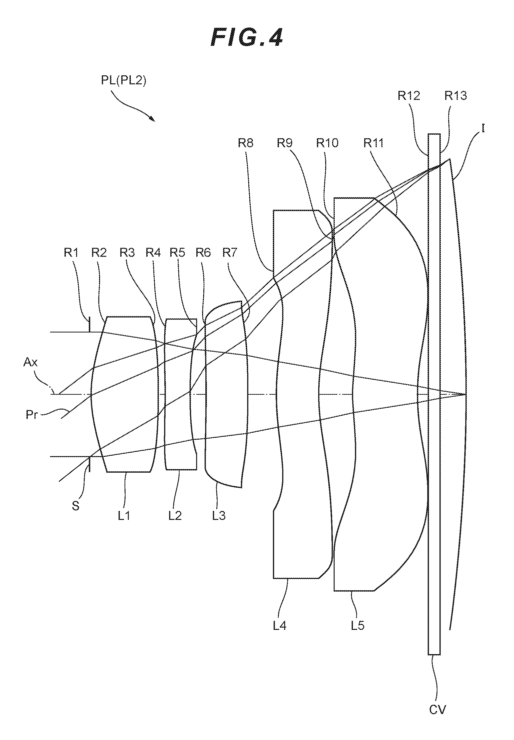
Example 2
Next, Example 2 of the present application is described with reference to FIG. 4, FIG. 5 and FIG. 6 and Table 2. FIG. 4 is a diagram illustrating a lens configuration of an imaging lens PL (PL2) according to Example 2. The imaging lens PL2 according to Example 2 includes: a first lens L1 having positive refractive power; a second lens L2 having negative refractive power; a third lens L3 having positive refractive power; a fourth lens L4 having negative refractive power; and a fifth lens L5 having negative refractive power which are disposed in order from the object along the optical axis Ax. The image surface I of the imaging lens PL1 is curved into a spherical shape to have a concave surface facing the object.
Both side lens surfaces of the first lens L1 are aspherical surfaces. An aperture stop S is provided close to the object-side lens surface of the first lens L1. Both side lens surfaces of the second lens L2 are aspherical surfaces. Both side lens surfaces of the third lens L3 are aspherical surfaces. Both side lens surfaces of the fourth lens L4 are aspherical surfaces. Both side lens surfaces of the fifth lens L5 are aspherical surfaces. A parallel flat plate CV, including a cover glass of the image sensor or the like, is disposed between the fifth lens L5 and the image surface I.
In Table 2 below, specification values in Example 2 are listed. The radii of curvature R of 1st to 13th surfaces in Table 2 respectively correspond to reference numerals R1 to R13 denoting 1st to 13th surfaces in FIG. 4. In Example 2, 2nd to 11th surfaces are aspherical lens surfaces.
TABLE-US-00002 TABLE 2 [Overall specifications] f 6.970 Fno 2.4 .omega. 38.2.degree. Y 5.5 TL 8.903 f12 8.646 [Lens specifications] Surface number R D nd .nu.d Object .infin. .infin. surface 1 .infin. 0.00000 (Aperture stop) 2* 3.64658 1.62431 1.59240 68.37 3* -30.19768 0.14912 4* -41.49215 0.60000 1.63970 23.52 5* 9.41985 0.38540 6* 47.05954 1.00000 1.53500 55.73 7* -181.22360 0.68159 8* 4.51098 1.00000 1.53500 55.73 9* 4.07514 0.83248 10* 6.79073 1.54348 1.53500 55.73 11* 5.01645 0.24553 12 .infin. 0.30000 1.51680 64.17 13 .infin. 0.54141 Image -37.34243 surface [Aspherical data] 2nd surface .kappa. = 0.000000, A4 = -2.715704E-03, A6 = -4.360297E-04, A8 = -2.517281E-04 A10 = 7.146433E-05, A12 = -1.694820E-05, A14 = 0.000000E+00 3rd surface .kappa. = 0.000000, A4 = -6.876456E-03, A6 = -2.528722E-03, A8 = 1.948210E-03 A10 = -6.060200E-04, A12 = 5.087436E-05, A14 = 0.000000E+00 4th surface .kappa. = 0.000000, A4 = 4.956749E-03, A6 = -6.990077E-04, A8 = 1.531199E-03 A10 = -3.432842E-04, A12 = 0.000000E+00, A14 = 0.000000E+00 5th surface .kappa. = 0.000000, A4 = 8.354094E-03, A6 = 1.951586E-03, A8 = -3.580310E-04 A10 = 2.925723E-04, A12 = -3.104880E-05, A14 = 0.000000E+00 6th surface .kappa. = 0.000000, A4 = -1.134513E-02, A6 = 1.061209E-03, A8 = 5.873748E-05 A10 = -2.576369E-04, A12 = 1.052375E-04, A14 = 0.000000E+00 7th surface .kappa. = 2913.770247, A4 = -1.874852E-02, A6 = 3.955280E-03, A8 = -7.931149E-04 A10 = 7.884854E-05, A12 = 3.139011E-06, A14 = 0.000000E+00 8th surface .kappa. = 0.000000, A4 = -2.583957E-02, A6 = 3.005184E-03, A8 = -3.268004E-04 A10 = 5.828312E-06, A12 = 7.226639E-07, A14 = 0.000000E+00 9th surface .kappa. = -0.955927, A4 = -2.271887E-02, A6 = 3.014968E-03, A8 = -2.936523E-04 A10 = 1.742106E-05, A12 = -4.976262E-07, A14 = 4.153938E-09 10th surface .kappa. = 0.000000, A4 = -2.128337E-02, A6 = 8.993966E-04, A8 = 2.960764E-05 A10 = -1.970782E-06, A12 = 8.429869E-09, A14 = -4.985640E-11 11th surface .kappa. = 0.000000, A4 = -1.427516E-02, A6 = 6.838593E-04, A8 = -2.298530E-05 A10 = -3.124829E-08, A12 = 4.435736E-09, A14 = 1.356162E-10 [Conditional expression corresponding value] Conditional expression (1) f/|f4| = 0.018 Conditional expression (2) f/f5 = -0.135 Conditional expression (3) f/f3 = 0.100 Conditional expression (4) f/f12 = 0.806 Conditional expression (5) SAG/f12 = -0.047 Conditional expression (6) (ra + rb)/(ra - rb) = 0.63 Conditional expression (7) |tb5 - ta5|/ta5 = 0.22 Conditional expression (8) |tb4 - ta4|/ta4 = 0.31 Conditional expression (9) |tb3 - ta3|/ta3 = 0.04
As described above, the conditional expressions (1) to (9) are all satisfied.
FIG. 5 is graphs illustrating longitudinal aberrations of the imaging lens PL2 according to Example 2. FIG. 6 is graphs illustrating lateral aberrations of the imaging lens PL2 according to Example 2. It can be seen in the aberration graphs that in Example 2, various aberrations are successfully corrected and an excellent imaging performance is achieved. All things considered, the excellent imaging performance of the image capturing device CMR including the imaging lens PL2 according to Example 2 can be guaranteed.
Example 3
Next, Example 3 according to the present application is described with reference to FIG. 7, FIG. 8 and FIG. 9 and Table 3. FIG. 7 is a diagram illustrating a lens configuration of an imaging lens PL (PL3) according to Example 3. The imaging lens PL3 according to Example 3 includes: a first lens L1 having positive refractive power; a second lens L2 having negative refractive power; a third lens L3 having positive refractive power; a fourth lens L4 having positive refractive power; and a fifth lens L5 having negative refractive power which are disposed in order from the object along the optical axis Ax. The image surface I of the imaging lens PL1 is curved into a spherical shape to have a concave surface facing the object.
Both side lens surfaces of the first lens L1 are aspherical surfaces. An aperture stop S is provided close to the object-side lens surface of the first lens L1. Both side lens surfaces of the second lens L2 are aspherical surfaces. Both side lens surfaces of the third lens L3 are aspherical surfaces. Both side lens surfaces of the fourth lens L4 are aspherical surfaces. Both side lens surfaces of the fifth lens L5 are aspherical surfaces. A parallel flat plate CV, including a cover glass of the image sensor or the like, is disposed between the fifth lens L5 and the image surface I.
In Table 3 below, specification values in Example 3 are listed. The radii of curvature R of 1st to 13th surfaces in Table 3 respectively correspond to reference numerals R1 to R13 denoting 1st to 13th surfaces in FIG. 7. In Example 3, 2nd to 11th surfaces are aspherical lens surfaces.
TABLE-US-00003 TABLE 3 [Overall specifications] f 7.101 Fno 2.4 .omega. 38.5.degree. Y 5.6 TL 8.905 f12 9.083 [Lens specifications] Surface number R D nd .nu.d Object .infin. .infin. surface 1 .infin. 0.00000 (Aperture stop) 2* 3.24518 1.32416 1.53500 55.73 3* -16.18366 0.10000 4* -17.52470 0.60000 1.63970 23.52 5* 9.48933 0.40329 6* 36.27256 1.09543 1.53500 55.73 7* 448.54174 0.64984 8* 4.32994 1.00984 1.53500 55.73 9* 4.17204 0.97554 10* 6.99096 1.51991 1.53500 55.73 11* 5.03712 0.24904 12 .infin. 0.30000 1.51680 64.17 13 .infin. 0.67790 Image -32.46033 surface [Aspherical data] 2nd surface .kappa. = 0.000000, A4 = -3.190306E-03, A6 = -8.734789E-04, A8 = -4.006341E-04 A10 = 5.406107E-05, A12 = -3.323754E-05, A14 = 0.000000E+00 3rd surface .kappa. = 0.000000, A4 = -8.881360E-03, A6 = -2.713028E-03, A8 = 1.810032E-03 A10 = -6.435194E-04, A12 = 6.024266E-05, A14 = 0.000000E+00 4th surface .kappa. = 0.000000, A4 = 4.420451E-03, A6 = -6.041313E-04, A8 = 1.610821E-03 A10 = -3.174168E-04, A12 = 0.000000E+00, A14 = 0.000000E+00 5th surface .kappa. = 0.000000, A4 = 8.598132E-03, A6 = 2.178340E-03, A8 = -3.110514E-04 A10 = 3.386680E-04, A12 = -3.255405E-05, A14 = 0.000000E+00 6th surface .kappa. = 0.000000, A4 = -1.186747E-02, A6 = 1.115319E-03, A8 = 4.477797E-05 A10 = -2.651464E-04, A12 = 1.114649E-04, A14 = 0.000000E+00 7th surface .kappa. = 42915.618794, A4 = -1.971404E-02, A6 = 4.067804E-03 A8 = -8.099559E-04, A10 = 7.672372E -05, A12 = 2.816204E-06 A14 = 0.000000E+00 8th surface .kappa. = 0.000000, A4 = -2.637800E-02, A6 = 3.032531E-03, A8 = -3.215881E-04 A10 = 5.048892E-06, A12 = 7.033046E-07, A14 = 0.000000E+00 9th surface .kappa. = -0.766243, A4 = -2.231013E-02, A6 = 3.009574E-03, A8 = -2.938002E-04 A10 = 1.738836E-05, A12 = -5.002018E-07, A14 = 4.170065E-09 10th surface .kappa. = 0.000000, A4 = -2.147054E-02, A6 = 8.977322E-04, A8 = 3.041425E-05 A10 = -1.960420E-06, A12 = 8.202088E-09, A14 = -8.301703E-11 11th surface .kappa. = 0.000000, A4 = -1.451709E-02, A6 = 7.214662E-04, A8 = -2.324613E-05 A10 = -2.796618E-08, A12 = 5.138298E-09, A14 = 9.081993E-11 [Conditional expression corresponding value] Conditional expression (1) f/|f4| = 0.041 Conditional expression (2) f/f5 = -0.154 Conditional expression (3) f/f3 = 0.096 Conditional expression (4) f/f12 = 0.782 Conditional expression (5) SAG/f12 = -0.053 Conditional expression (6) (ra + rb)/(ra - rb) = 0.30 Conditional expression (7) |tb5-ta5|/ta5 = 0.31 Conditional expression (8) |tb4-ta4|/ta4 = 0.24 Conditional expression (9) |tb3-ta3|/ta3 = 0.03
As described above, the conditional expressions (1) to (9) are all satisfied.
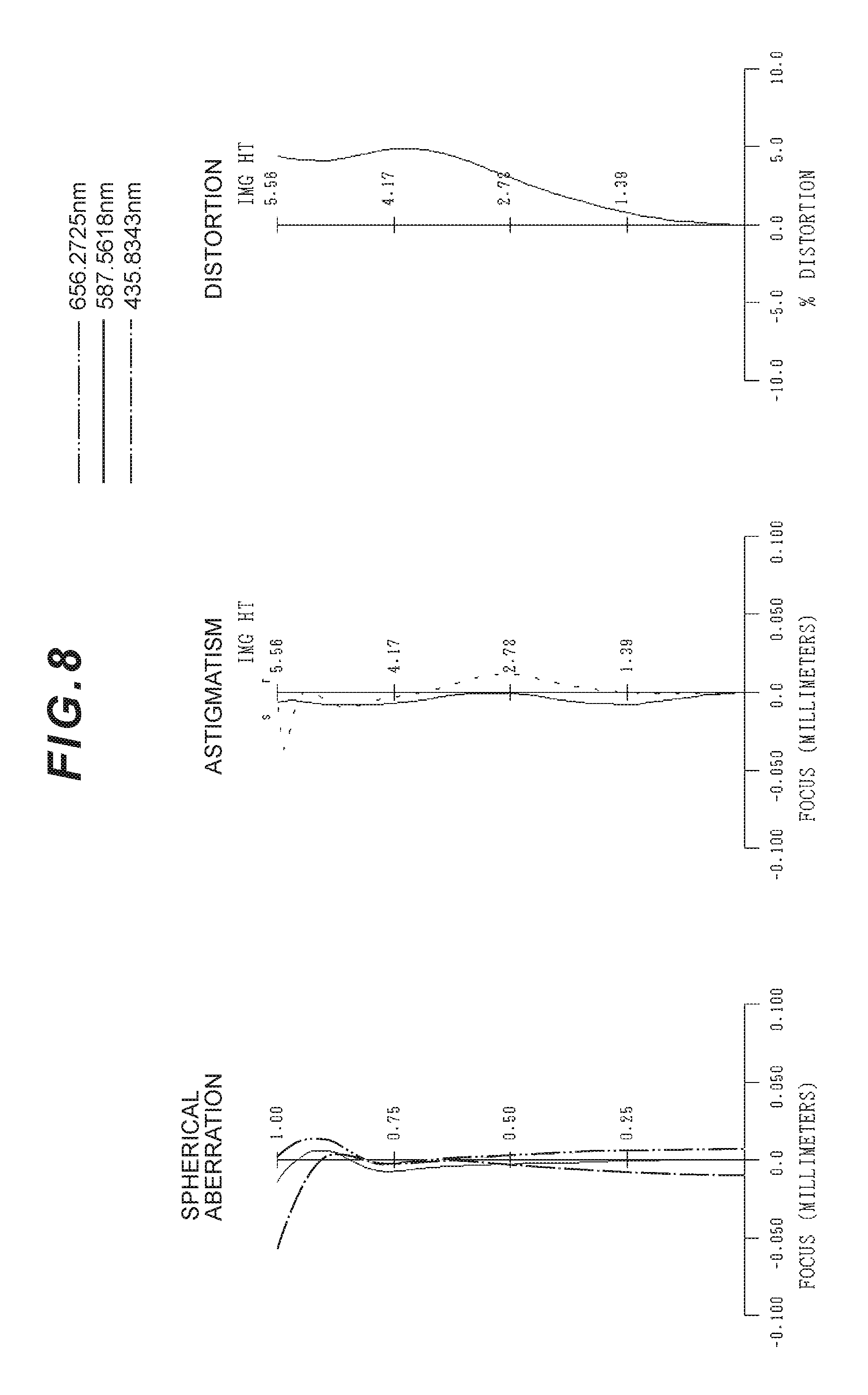
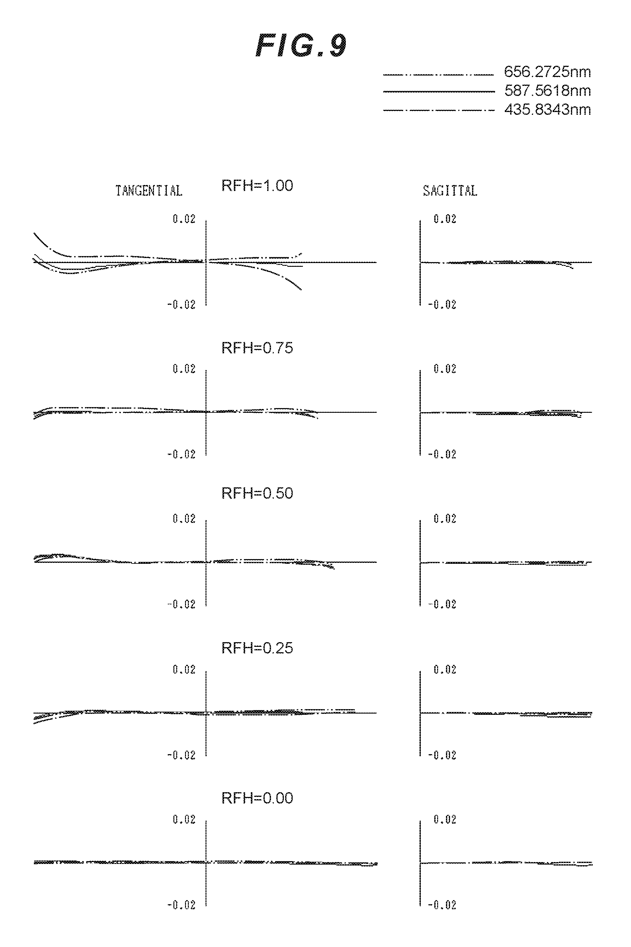
FIG. 8 is graphs illustrating longitudinal aberrations of the imaging lens PL3 according to Example 3. FIG. 9 is graphs illustrating lateral aberrations of the imaging lens PL3 according to Example 3. It can be seen in the aberration graphs that in Example 3, various aberrations are successfully corrected and an excellent imaging performance is achieved. All things considered, the excellent imaging performance of the image capturing device CMR including the imaging lens PL3 according to Example 3 can be guaranteed.
Example 4
Next, Example 4 according to the present application is described with reference to FIG. 10, FIG. 11 and FIG. 12 and Table 4. FIG. 10 is a diagram illustrating a lens configuration of an imaging lens PL (PL4) according to Example 4. The imaging lens PL4 according to Example 4 includes: a first lens L1 having positive refractive power; a second lens L2 having negative refractive power; a third lens L3 having positive refractive power; a fourth lens L4 having positive refractive power; and a fifth lens L5 having negative refractive power which are disposed in order from the object along the optical axis Ax. The image surface I of the imaging lens PL1 is curved into a spherical shape to have a concave surface facing the object.
Both side lens surfaces of the first lens L1 are aspherical surfaces. An aperture stop S is provided close to the object-side lens surface of the first lens L1. Both side lens surfaces of the second lens L2 are aspherical surfaces. Both side lens surfaces of the third lens L3 are aspherical surfaces. Both side lens surfaces of the fourth lens L4 are aspherical surfaces. Both side lens surfaces of the fifth lens L5 are aspherical surfaces.
In Table 4 below, specification values in Example 4 are listed. The radii of curvature R of 1st to 11th surfaces in Table 4 respectively correspond to reference numerals R1 to R11 denoting 1st to 11th surfaces in FIG. 10. In Example 4, 2nd to 11th surfaces are aspherical lens surfaces.
TABLE-US-00004 TABLE 4 [Overall specifications] f 6.630 Fno 2.2 .omega. 40.4.degree. Y 5.6 TL 8.445 f12 9.063 [Lens specifications] Surface number R D nd .nu.d 1 .infin. 0.00000 (Aperture stop) 2* 3.16128 1.25910 1.53500 55.73 3* -17.46490 0.10000 4* -23.08917 0.60000 1.63970 23.52 5* 8.03860 0.39971 6* 33.47049 1.00000 1.53500 55.73 7* 415.97983 0.59028 8* 4.03603 1.00000 1.53500 55.73 9* 4.34293 0.99615 10* 6.93635 1.54225 1.53500 55.73 11* 4.87208 Image -28.43542 surface [Aspherical data] 2nd surface .kappa. = 0.000000, A4 = -3.044112E-03, A6 = -6.657011E-04, A8 = -6.384812E-04 A10 = 1.379670E-04, A12 = -5.876162E-05, A14 = 0.000000E+00 3rd surface .kappa. = 0.000000, A4 = -8.452881E-03, A6 = -4.126613E-03, A8 = 1.760778E-03 A10 = -5.237809E-04, A12 = 4.403434E-05, A14 = 0.000000E+00 4th surface .kappa. = 0.000000, A4 = 1.612968E-03, A6 = -1.418453E-03, A8 = 1.322713E-03 A10 = -1.535445E-04, A12 = 0.000000E+00, A14 = 0.000000E+00 5th surface .kappa. = 0.000000, A4 = 7.136121E-03, A6 = 2.225260E-03, A8 = -4.906232E-04 A10 = 3.506202E-04, A12 = -3.126885E-05, A14 = 0.000000E+00 6th surface .kappa. = 0.000000, A4 = -1.041022E-02, A6 = 1.341252E-03, A8 = 4.703229E-05 A10 = -2.925072E-04, A12 = 1.040511E-04, A14 = 0.000000E+00 7th surface .kappa. = 36588.098197, A4 = -2.206946E-02, A6 = 4.964707E-03 A8 = -8.798997E-04, A10 = 6.364621E-05, A12 = 5.903525E-06 A14 = 0.000000E+00 8th surface .kappa. = 0.000000, A4 = -2.872039E-02, A6 = 3.525770E-03, A8 = -3.783690E-04 A10 = 6.570503E-06, A12 = 7.701422E-07, A14 = 0.000000E+00 9th surface .kappa. = -0.704637, A4 = -2.186476E-02, A6 = 2.967636E-03, A8 = -2.938684E-04 A10 = 1.738456E-05, A12 = -4.996629E-07, A14 = 4.449369E-09 10th surface .kappa. = 0.000000, A4 = -2.206083E-02, A6 = 9.031426E-04, A8 = 3.013751E-05 A10 = -1.974726E-06, A12 = 9.623570E-09, A14 = 6.835921E-11 11th surface .kappa. = 0.000000, A4 = -1.448008E-02, A6 = 6.947833E-04, A8 = -2.448315E-05 A10 = -5.647896E-08, A12 = 5.275035E-09, A14 = 8.315521E-11 [Conditional expression corresponding value] Conditional expression (1) f/|f4| = 0.133 Conditional expression (2) f/f5 = -0.160 Conditional expression (3) f/f3 = 0.098 Conditional expression (4) f/f12 = 0.732 Conditional expression (5) SAG/f12 = -0.061 Conditional expression (6) (ra + rb)/(ra - rb) = 0.48 Conditional expression (7) |tb5 - ta5|/ta5 = 0.30 Conditional expression (8) |tb4 - ta4|/ta4 = 0.23 Conditional expression (9) |tb3 - ta3|/ta3 = 0.05
As described above, the conditional expressions (1) to (9) are all satisfied.
FIG. 11 is graphs illustrating longitudinal aberrations of the imaging lens PL4 according to Example 4. FIG. 12 is graphs illustrating lateral aberrations of the imaging lens PL4 according to Example 4. It can be seen in the aberration graphs that in Example 4, various aberrations are successfully corrected and an excellent imaging performance is achieved. All things considered, the excellent imaging performance of the image capturing device CMR including the imaging lens PL4 according to Example 4 can be guaranteed.
Example 5
Next, Example 5 according to the present application is described with reference to FIG. 13, FIG. 14 and FIG. 15 and Table 5. FIG. 13 is a diagram illustrating a lens configuration of an imaging lens PL (PL5) according to Example 5. The imaging lens PL5 according to Example 5 includes: a first lens L1 having positive refractive power; a second lens L2 having negative refractive power; a third lens L3 having positive refractive power; a fourth lens L4 having positive refractive power; and a fifth lens L5 having negative refractive power which are disposed in order from the object along the optical axis Ax. The image surface I of the imaging lens PL1 is curved into a spherical shape to have a concave surface facing the object.
Both side lens surfaces of the first lens L1 are aspherical surfaces. An aperture stop S is provided close to the object-side lens surface of the first lens L1. Both side lens surfaces of the second lens L2 are aspherical surfaces. Both side lens surfaces of the third lens L3 are aspherical surfaces. A bonded-multilayer diffractive optical element (DOE) is provided on an object-side lens surface of the third lens L3. Both side lens surfaces of the fourth lens L4 are aspherical surfaces. Both side lens surfaces of the fifth lens L5 are aspherical surfaces.
In Table 5 below, specification values in Example 5 are listed. The radii of curvature R of 1st to 13th surfaces in Table 5 respectively correspond to reference numerals R1 to R13 denoting 1st to 13th surfaces in FIG. 13. In Example 5, 2nd to 13th surfaces are aspherical lens surfaces. In Example 5, the 7th surface has a lens surface as a diffractive surface.
TABLE-US-00005 TABLE 5 [Overall specifications] f 6.514 Fno 2.0 .omega. 40.7.degree. Y 5.6 TL 8.442 f12 8.404 [Lens specifications] Surface number R D nd .nu.d 1 .infin. 0.00000 (Aperture stop) 2* 3.10486 1.16474 1.53500 55.73 3* -56.70253 0.10000 4* -32.47744 0.60000 1.63970 23.52 5* 11.31125 0.45881 6* 87.74058 0.01000 1.55710 49.70 7** 87.74058 0.01000 1.52780 33.40 (Diffractive surface) 8* 87.74058 1.12881 1.53500 55.73 9* 439.90364 0.52262 10* 4.44201 1.00000 1.53500 55.73 11* 4.66202 0.93883 12* 6.82646 1.61399 1.53500 55.73 13* 4.97254 0.89436 Image -29.46109 surface [Aspherical data] 2nd surface .kappa. = 0.000000, A4 = -2.617921E-03, A6 = -2.836382E-04, A8 = -7.209507E-04 A10 = 1.355608E-04, A12 = -3.889423E-05, A14 = 0.000000E+00 3rd surface .kappa. = 0.000000, A4 = -6.209105E-03, A6 = -3.638046E-03, A8 = 1.797303E-03 A10 = -4.716609E-04, A12 = 3.168969E-05, A14 = 0.000000E+00 4th surface .kappa. = 0.000000, A4 = 3.747415E-03, A6 = -6.857342E-04, A8 = 1.575670E-03 A10 = -2.097313E-04, A12 = 0.000000E+00, A14 = 0.000000E+00 5th surface .kappa. = 0.000000, A4 = 6.816408E-03, A6 = 2.892403E-03, A8 = -4.648327E-04 A10 = 3.394889E-04, A12 = -1.654776E-05, A14 = 0.000000E+00 6th surface .kappa. = 0.000000, A4 = -1.194834E-02, A6 = 1.052826E-03, A8 = 8.719881E-07 A10 = -2.881473E-04, A12 = 1.082776E-04, A14 = 0.000000E+00 7th surface .kappa. = 0.000000, A4 = -1.194834E-02, A6 = 1.052826E-03, A8 = 8.719881E-07 A10 = -2.881473E-04, A12 = 1.082776E-04, A14 = 0.000000E+00 8th surface .kappa. = 0.000000, A4 = -1.194834E-02, A6 = 1.052826E-03, A8 = 8.719881E-07 A10 = -2.881473E-04, A12 = 1.082776E-04, A14 = 0.000000E+00 9th surface k = 39005.261275, A4 = -2.356145E-02, A6 = 4.845568E-03 A8 = -8.795236E-04, A10 = 6.491763E-05, A12 = 6.304707E-06 A14 = 0.000000E+00 10th surface .kappa. = 0.000000, A4 = -2.949000E-02, A6 = 3.600307E-03, A8 = -4.070518E-04 A10 = 6.785977E-06, A12 = 1.032481E-06, A14 = 0.000000E+00 11th surface .kappa. = -0.758382, A4 = -2.197533E-02, A6 = 2.987014E-03, A8 = -2.920380E-04 A10 = 1.739580E-05, A12 = -5.029644E-07, A14 = 4.165444E-09 12th surface .kappa. = 0.000000, A4 = -2.217316E-02, A6 = 9.063406E-04, A8 = 3.009417E-05 A10 = -1.976162E-06, A12 = 9.395528E-09, A14 = 4.181703E-11 13th surface .kappa. = 0.000000, A4 = -1.425604E-02, A6 = 7.136896E-04, A8 = -2.332945E-05 A10 = -4.444158E-08, A12 = 4.777729E-09, A14 = 1.574126E-11 [Diffractive surface data] 7th surface m = 1 C2 = -1.943400E-03,C4 = 1.987561E-04,C6 = -8.651480E-05 C8 = -1.874098E-05 [Conditional expression corresponding value] Conditional expression (1) f/|f4| = 0.096 Conditional expression (2) f/f5 = -0.133 Conditional expression (3) f/f3 = 0.059 Conditional expression (4) f/f12 = 0.775 Conditional expression (5) SAG/f12 = -0.063 Conditional expression (6) (ra + rb)/(ra - rb) = 0.48 Conditional expression (7) |tb5 - ta5|/ta5 = 0.34 Conditional expression (8) |tb4 - ta4|/ta4 = 0.27 Conditional expression (9) |tb3 - ta3|/ta3 = 0.03
As described above, the conditional expressions (1) to (9) are all satisfied.
FIG. 14 is graphs illustrating longitudinal aberrations of the imaging lens PL5 according to Example 5. FIG. 15 is graphs illustrating lateral aberrations of the imaging lens PL5 according to Example 5. It can be seen in the aberration graphs that in Example 5, various aberrations are successfully corrected and an excellent imaging performance is achieved. All things considered, the excellent imaging performance of the image capturing device CMR including the imaging lens PL5 according to Example 5 can be guaranteed.
With Examples described above, an imaging lens having a short entire length and a favorable imaging performance, and an image capturing device including the same can be implemented.
In Examples described above, the image surface I of the imaging lens PL is curved to have a spherical concave surface facing the object. However, this should not be construed in a limiting sense. For example, another curved shape such as an aspherical curved shape may be employed.
In Example 5, the bonded-multilayer diffractive optical element (DOE) is provided on the object-side lens surface of the third lens L3. However, this should not be construed in a limiting sense. The bonded-multilayer diffractive optical element may be provided on at least one of the lens surfaces of the first lens L1, the second lens L2, the fourth lens L4, and the fifth lens L5. The bonded-multilayer diffractive optical element may be provided on at least one of the lens surfaces of the first lens L1, the second lens L2, the third lens L3, the fourth lens L4, and the fifth lens L5 not only in Example 5 described above but also in Example 1 to Example 4 described above.
In Example 1 to Example 3 described above, the parallel flat plate CV is disposed between the fifth lens L5 and the image surface I. However, this should not be construed in a limiting sense. The parallel flat plate CV may not be provided. In Example 4 and Example 5 described above, a parallel flat plate including a cover glass of the image sensor or the like may be disposed between the fifth lens L5 and the image surface I.
In Examples described above, the aperture stop S, disposed close to the first lens L1, is preferably disposed close to an object-side lens surface of the first lens L1 for the sake of aberration correction. The aperture stop may not be provided as a component, and its function may be achieved with a frame of a lens.
EXPLANATION OF NUMERALS AND CHARACTERS
CMR image capturing device SR image sensor PL imaging lens L1 first lens L2 second lens L3 third lens L4 fourth lens L5 fifth lens S aperture stop I image surface DOE diffractive optical element
* * * * *
D00000
D00001
D00002
D00003
D00004
D00005
D00006
D00007
D00008
D00009
D00010
D00011
D00012

D00013

D00014
D00015
D00016

D00017

XML
uspto.report is an independent third-party trademark research tool that is not affiliated, endorsed, or sponsored by the United States Patent and Trademark Office (USPTO) or any other governmental organization. The information provided by uspto.report is based on publicly available data at the time of writing and is intended for informational purposes only.
While we strive to provide accurate and up-to-date information, we do not guarantee the accuracy, completeness, reliability, or suitability of the information displayed on this site. The use of this site is at your own risk. Any reliance you place on such information is therefore strictly at your own risk.
All official trademark data, including owner information, should be verified by visiting the official USPTO website at www.uspto.gov. This site is not intended to replace professional legal advice and should not be used as a substitute for consulting with a legal professional who is knowledgeable about trademark law.