Target-analyte permeation testing instrument with sensor feed line conditioning system
Ascheman Nov
U.S. patent number 10,488,318 [Application Number 15/100,448] was granted by the patent office on 2019-11-26 for target-analyte permeation testing instrument with sensor feed line conditioning system. This patent grant is currently assigned to MOCON, INC.. The grantee listed for this patent is MOCON, INC.. Invention is credited to Timothy A. Ascheman.

| United States Patent | 10,488,318 |
| Ascheman | November 26, 2019 |
Target-analyte permeation testing instrument with sensor feed line conditioning system
Abstract
A target-analyte permeation testing instrument (10) characterized by a sensor feed line (300.sub.nB.sub.out and 300.sub.5) conditioning system.
| Inventors: | Ascheman; Timothy A. (Elk River, MN) | ||||||||||
|---|---|---|---|---|---|---|---|---|---|---|---|
| Applicant: |
|
||||||||||
| Assignee: | MOCON, INC. (Minneapolis,
MN) |
||||||||||
| Family ID: | 53879127 | ||||||||||
| Appl. No.: | 15/100,448 | ||||||||||
| Filed: | February 24, 2015 | ||||||||||
| PCT Filed: | February 24, 2015 | ||||||||||
| PCT No.: | PCT/US2015/017196 | ||||||||||
| 371(c)(1),(2),(4) Date: | May 31, 2016 | ||||||||||
| PCT Pub. No.: | WO2015/127415 | ||||||||||
| PCT Pub. Date: | August 27, 2015 |
Prior Publication Data
| Document Identifier | Publication Date | |
|---|---|---|
| US 20160299049 A1 | Oct 13, 2016 | |
Related U.S. Patent Documents
| Application Number | Filing Date | Patent Number | Issue Date | ||
|---|---|---|---|---|---|
| 61943772 | Feb 24, 2014 | ||||
| Current U.S. Class: | 1/1 |
| Current CPC Class: | G01N 35/1097 (20130101); G01N 33/004 (20130101); G01N 15/0806 (20130101); G01N 35/00693 (20130101); G01N 35/00712 (20130101); G01N 15/0826 (20130101); G01N 2015/086 (20130101) |
| Current International Class: | G01N 15/08 (20060101); G01N 35/10 (20060101); G01N 33/00 (20060101); G01N 35/00 (20060101) |
| Field of Search: | ;73/38 |
References Cited [Referenced By]
U.S. Patent Documents
| 3498110 | March 1970 | Brun |
| 3590634 | July 1971 | Pasternak et al. |
| 3618361 | November 1971 | Stephens et al. |
| 4464927 | August 1984 | Reid |
| 4656865 | April 1987 | Callan |
| 4667153 | May 1987 | Doyle |
| 4791822 | December 1988 | Penny |
| 4852389 | August 1989 | Mayer |
| 4922758 | May 1990 | Penny |
| 4944180 | July 1990 | Tou et al. |
| 5088316 | February 1992 | McKelvey |
| 5107696 | April 1992 | Mayer |
| 5361625 | November 1994 | Ylvisaker |
| 6066243 | May 2000 | Anderson et al. |
| 7178384 | February 2007 | Bujas et al. |
| 7571749 | August 2009 | Stochi |
| 7578208 | August 2009 | Mayer |
| 7818996 | October 2010 | Gevers |
| 8821614 | September 2014 | Albenze |
| 2002/0045243 | April 2002 | Laska et al. |
| 2003/0019747 | January 2003 | Saffell et al. |
| 2003/0074945 | April 2003 | Engle et al. |
| 2003/0074954 | April 2003 | Engle |
| 2004/0040372 | March 2004 | Plester |
| 2005/0211572 | September 2005 | Buck et al. |
| 2007/0271998 | November 2007 | Woolfenden |
| 2008/0028834 | February 2008 | Gevers |
| 2008/0060417 | March 2008 | DeRoos |
| 2008/0060418 | March 2008 | DeRoos et al. |
| 2010/0054998 | March 2010 | Mayer et al. |
| 2010/0223979 | September 2010 | Ploehn et al. |
| 2010/0274515 | October 2010 | Hoss et al. |
| 2012/0262298 | October 2012 | Bohm et al. |
| 2012/0330596 | December 2012 | Kouznetsov |
| 2014/0238101 | August 2014 | Mealy, Jr. et al. |
| 2017/0072157 | March 2017 | Tolmie et al. |
| 2432452 | Jun 2002 | CA | |||
| 2113764 | Nov 2009 | EP | |||
| 62165545 | Jul 1987 | JP | |||
| 63236943 | Oct 1988 | JP | |||
| 200572110 | Mar 2005 | JP | |||
| 2006094838 | Apr 2006 | JP | |||
| 98/03868 | Jan 1998 | WO | |||
| 2010029282 | Apr 2001 | WO | |||
| 2013143029 | Mar 2013 | WO | |||
Other References
|
"Thermo Environmental Instruments Model 48C Trace Level Gas Filter Correlation Carbon Monoxide Analyzer", Standard Operating Procesures, SOP Version No. 2.0, May 6, 2009, p. 1-32. cited by applicant . Beyer, David Stewart; "Industrial Accident Prevention"; Book; Houghton Mifflin Company, Boston and New York; 1916. cited by applicant. |
Primary Examiner: Fitzgerald; John
Attorney, Agent or Firm: Sherrill Law Offices, PLLC
Claims
I claim:
1. A target-analyte permeation testing instrument for measuring target-analyte permeation rate of a test film in a test cell, the instrument having (-) a target-analyte sensor, and (-) at least one test cell operable for retaining a test film in a testing chamber so as to sealingly divide the testing chamber into a driving chamber and a sensing chamber, the target-analyte permeation testing instrument characterized by (i) a length of common conduit in fluid communication with the shared target-analyte sensor, (ii) individual dedicated lengths of conduit, each in fluid communication with the length of common conduit and each operable for delivering a fluid subjected by the instrument to a different target-analyte exposure experience, with at least one of the individual dedicated lengths of conduit in fluid communication with the sensing chamber of the at least one test cell, (iii) a dedicated valve associated with each dedicated length of conduit operable between venting and flow through states, and (iv) a common valve associated with the length of common conduit operable between venting and flow through states.
2. A method of simultaneously measuring target-analyte transmission rate through a plurality of test films utilizing the target-analyte permeation testing instrument of claim 1, comprising the steps of: (a) obtaining a target-analyte permeation testing instrument according to claim 1, (b) loading a test film into each of at least two test cells, (c) providing a flow of target-analyte containing driving gas through the driving chamber of each test cell containing a test film, and (d) providing a flow of inert carrier gas through the sensing chamber of each test cell containing a test film, followed by the sequential steps of: (e) measuring target-analyte concentration in the sensing chamber of a first test cell by setting the associated dedicate valve to flow-through, setting the common valve to flow-through, setting all other dedicated valves to vent, and measuring concentration of target-analyte in fluid communication with the target-analyte sensor, (f) conditioning the instrument for ensuing measurement of target-analyte concentration in the sensing chamber of a second test cell for a conditioning period by setting the common valve to vent, setting the dedicated valve associated with the sensing chamber of the first test cell to vent, setting the dedicate valve associated with the sensing chamber of the second test cell to flow-through, and leaving all other dedicated valves to vent, and (g) measuring target-analyte concentration in the sensing chamber of the second test cell by setting the common valve to flow-through.
Description
BACKGROUND
Permeation instruments are used to measure the transmission rate of a target analyte, such as oxygen, carbon dioxide or water vapor, through various samples, such as membranes, films, envelopes, bottles, packages, containers, etc. (hereinafter collectively referenced as "test films" for convenience). Typical test films are polymeric packaging films such as those constructed from low density polyethylene (LDPE), high density polyethylene (HDPE), oriented polypropylene (OPP), polyethylene terepthalate (PET), polyvinylidene chloride (PVTDC), etc. Typically, the film to be tested is positioned within a test chamber to sealing separate the chamber into first and second chambers. The first chamber (commonly referenced as the driving or analyte chamber) is filled with a gas containing a known concentration of the target analyte (commonly referenced as a driving gas). The second chamber (commonly referenced as the sensing chamber) is flushed with an inert gas (commonly referenced as a carrier gas) to remove any target analyte from the cell. A sensor for the target analyte is placed in fluid communication with the sensing chamber for detecting the presence of target analyte that has migrated into the sensing chamber from the driving chamber through the test film. Exemplary permeation instruments for measuring the transmission rate of oxygen (O.sub.2), carbon dioxide (CO.sub.2) and water vapor (H.sub.2O) through test films are commercially available from Mocon, Inc. of Minneapolis, Minn. under the designations OXTRAN, PERMATRAN-C and PERMATRAN-W, respectively.
Permeation testing instruments employ a very low mass flow through rate through the instrument to limit the creation of any pressure differentials in the instrument that could impact humidification of the test and/or carrier gases or create a pressure-induced driving force across a test film. This low mass flow rate through the instrument imposes a significant time delay between measurements from different testing cells as the feed line to the sensor is flushed with the carrier gas from the sensing chamber of the newly selected testing cell.
A substantial need exists for a permeation instrument capable of contemporaneously measuring target-analyte transmission rates from a plurality of testing cells with minimal changeover time between measurements from different testing cells.
SUMMARY OF THE INVENTION
A first aspect of the invention is a target-analyte permeation testing instrument for measuring target-analyte permeation rate of a test film in test cell, characterized by a sensor feed line conditioning system.
A first embodiment of the instrument has a target-analyte sensor and at least one test cell operable for retaining a test film in a testing chamber so as to sealingly divide the testing chamber into a driving chamber and a sensing chamber. The target-analyte permeation testing instrument is characterized by (i) a length of common conduit in fluid communication with the shared target-analyte sensor, (ii) individual dedicated lengths of conduit, each in fluid communication with the length of common conduit and each operable for delivering a fluid subjected by the instrument to a different target-analyte exposure experience, with at least one of the individual dedicated lengths of conduit in fluid communication with the sensing chamber of the at least one test cell, (iii) a dedicated valve associated with each dedicated length of conduit operable between venting and flow through states, and (iv) a common valve associated with the length of common conduit operable between venting and flow through states.
A second embodiment of the instrument has a shared target-analyte sensor and a plurality of test cells each defining a testing chamber with each test cell operable for retaining a test film to sealingly divide the testing chamber into a driving chamber and a sensing chamber. The target-analyte permeation testing instrument is characterized by (i) a length of common conduit in fluid communication with the shared target-analyte sensor, (ii) individual dedicated lengths of conduit in fluid communication with each of an associated sensing chamber and the length of common conduit, each dedicated length of conduit operable for carrying fluid from the sensing chamber of an associated test cell to the length of common conduit, (iii) a dedicated valve associated with each dedicated length of conduit operable between venting and flow through states, and (iv) a common valve associated with the length of common conduit operable between venting and flow through states.
A second aspect of the invention is a method of measuring target-analyte transmission rate through a test film utilizing a target-analyte permeation testing instrument according to the first aspect of the invention.
A first embodiment of the second aspect of the invention is a method of measuring target-analyte transmission rate through a test film utilizing a target-analyte permeation testing instrument according to the first embodiment of the first aspect of the invention. The method includes initial set-up and subsequent testing steps. The set-up steps include the steps of (i) obtaining a target-analyte permeation testing instrument according to the first embodiment of the first aspect of the invention, (ii) loading a test film into the at least one test cell, (iii) providing a flow of target-analyte containing driving gas through the driving chamber of the at least one test cell containing a test film, and (iv) providing a flow of inert carrier gas through the sensing chamber of the at least one test cell containing a test film. The testing steps includes the sequential steps of (a) measuring target-analyte concentration in the sensing chamber of the at least one test cell by setting the dedicated valve for the individual dedicated length of conduit associated with the sensing chamber of the at least one test cell to flow-through, setting the common valve to flow-through, setting all other dedicated valves to vent, and measuring concentration of target-analyte in fluid communication with the target-analyte sensor, (b) conditioning the instrument for ensuing measurement of target-analyte concentration in a fluid delivered to the common length of conduit through a different individual dedicated length of conduit for a conditioning period by setting the common valve to vent, setting the dedicated valve for the individual dedicated length of conduit associated with the sensing chamber of the at least one test cell to vent, setting the dedicate valve associated with the different individual dedicated length of conduit to flow-through, and leaving all other dedicated valves to vent, and (c) measuring target-analyte concentration in the fluid delivered to the common length of conduit through a different individual dedicated length of conduit by setting the common valve to flow-through.
A second embodiment of the second aspect of the invention is a method of simultaneously measuring target-analyte transmission rate through a plurality of test films utilizing a target-analyte permeation testing instrument according to the second embodiment of the first aspect of the invention. The method includes initial set-up and subsequent testing steps. The set-up steps include the steps of (i) obtaining a target-analyte permeation testing instrument according to the second embodiment of the first aspect of the invention, (ii) loading a test film into each of at least two test cells, (iii) providing a flow of target-analyte containing driving gas through the driving chamber of each test cell containing a test film, and (iv) providing a flow of inert carrier gas through the sensing chamber of each test cell containing a test film. The testing steps includes the sequential steps of (a) measuring target-analyte concentration in the sensing chamber of a first test cell by setting the associated dedicate valve to flow-through, setting the common valve to flow-through, setting all other dedicated valves to vent, and measuring concentration of target-analyte in fluid communication with the target-analyte sensor, (b) conditioning the instrument for ensuing measurement of target-analyte concentration in the sensing chamber of a second test cell for a conditioning period by setting the common valve to vent, setting the dedicated valve associated with the sensing chamber of the first test cell to vent, setting the dedicate valve associated with the sensing chamber of the second test cell to flow-through, and leaving all other dedicated valves to vent, and (c) measuring target-analyte concentration in the sensing chamber of the second test cell by setting the common valve to flow-through.
BRIEF DESCRIPTION OF THE DRAWINGS
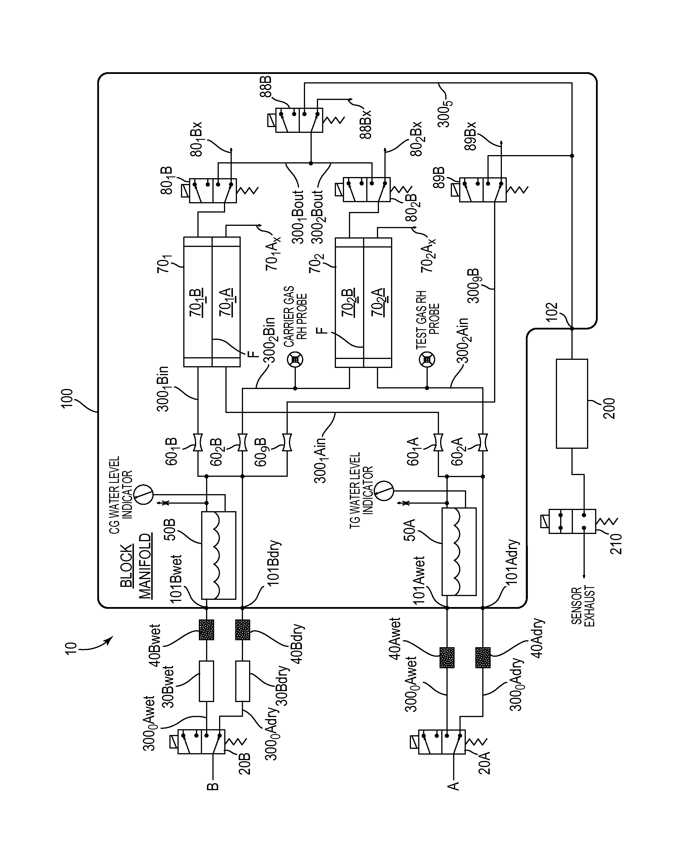
FIG. 1 is a schematic plumbing diagram of one embodiment of the invention.
DETAILED DESCRIPTION OF A PREFERRED EMBODIMENT
TABLE-US-00001 Nomenclature Table 10 Target-Analyte Permeation Testing Instrument 20A Test Gas RH Control Valve 20B Carrier Gas RH Control Valve 30B.sub.wet Catalyst Chamber in Wet Carrier Gas Line 30B.sub.dry Catalyst Chamber in Dry Carrier Gas Line 40A.sub.wet Particle Filter in Wet Test Gas Line 40A.sub.dry Particle Filter in Dry Test Gas Line 40B.sub.wet Particle Filter in Wet Carrier Gas Line 40B.sub.dry Particle Filter in Dry Carrier Gas Line 50A Water Reservoir for Test Gas 50B Water Reservoir for Carrier Gas 60.sub.n Capillary Restrictors 60.sub.1A Capillary Restrictor for Test Gas Channel to First Test Cell 60.sub.2A Capillary Restrictor for Test Gas Channel to Second Test Cell 60.sub.1B Capillary Restrictor for Carrier Gas Channel to First Test Cell 60.sub.2B Capillary Restrictor for Carrier Gas Channel to Second Test Cell 60.sub.9B Capillary Restrictor for Carrier Gas Channel to Rezero Valve 70.sub.n Testing Cells 70.sub.nA Driving Chamber of Test Cell n 70.sub.nB Sensing Chamber of Test Cell n 70.sub.nAx Exhaust from Driving Chamber of Test Cell n 70.sub.1 First Testing Cells 70.sub.1A Driving Chamber of First Test Cell 70.sub.1Ax Exhaust from Driving Chamber of First Test Cell 70.sub.1B Sensing Chamber of First Test Cell 70.sub.2 Second Testing Cells 70.sub.2A Driving Chamber of Second Test Cell 70.sub.2Ax Exhaust from Driving Chamber of Second Test Cell 70.sub.2B Sensing Chamber of Second Test Cell 80.sub.nB Carrier Gas Sensing Chamber Exit Valve for Testing Cell n 80.sub.1B First Test Cell Carrier Gas Exit Valve 80.sub.1Bx Exhaust from Sensing Chamber of First Test Cell 80.sub.2B Second Test Cell Carrier Gas Exit Valve 80.sub.2Bx Exhaust from Sensing Chamber of Second Test Cell 88B Common Channel Conditioning Valve 88Bx Exhaust from Common Channel Conditioning Valve 89B Rezero Valve 89Bx Exhaust from Rezero Valve 100 Block Manifold 101A.sub.wet Test Gas Water Reservoir Inlet Port 101A.sub.dry Test Gas Water Reservoir Bypass Inlet Port 101B.sub.wet Carrier Gas Water Reservoir Inlet Port 101B.sub.dry Carrier Gas Water Reservoir Bypass Inlet Port 102 Carrier Gas Outlet Port to Sensor 200 Target-Analyte Sensor 210 Sensor Exhaust Valve 300.sub.n Gas Flow Line n 300.sub.0A.sub.wet Test Gas Water Reservoir Inlet Line 300.sub.0A.sub.dry Test Gas Water Reservoir Bypass Inlet Line 300.sub.0B.sub.wet Carrier Gas Water Reservoir Inlet Line 300.sub.0B.sub.dry Carrier Gas Water Reservoir Bypass Inlet Line 300.sub.1A.sub.in Test Gas First Testing Cell Inlet Line 300.sub.1B.sub.in Carrier Gas First Testing Cell Inlet Line 300.sub.2A.sub.in Test Gas Second Testing Cell Inlet Line 300.sub.2B.sub.in Carrier Gas Second Testing Cell Inlet Line 300.sub.nB.sub.out Carrier Gas Outlet Line for Testing Cell n 300.sub.1B.sub.out Carrier Gas First Testing Cell Outlet Line 300.sub.2B.sub.out Carrier Gas Second Testing Cell Outlet Line 300.sub.5 Shared Carrier Gas Testing Cell Outlet Line 300.sub.9B Carrier Gas Rezero Line A Driving or Test Gas Source B Inert or Carrier Gas Source F Test Film
Description
Referring generally to FIG. 1, the invention is a target-analyte permeation testing instrument 10 characterized by a sensor feed line conditioning system.
The instrument 10 has a target-analyte sensor 200 and a plurality of test cells 70.sub.n for measuring target-analyte permeation rate of test films F.sub.n. Each test cell 70.sub.n defines a testing chamber and is operable for retaining a test film F to sealingly divide the testing chamber into a driving chamber 70.sub.nA and a sensing chamber 70.sub.nB. The cells 70.sub.n are preferably secured to a block manifold 100, preferably a solid block cast metal manifold 100 into which the appropriate channels and compartments are formed. A plurality of channels 300.sub.n are in fluid communication with the testing chamber of each cell 70.sub.n, a pressurized source of driving gas A, a pressurized source of inert gas B, and a target-analyte sensor 200. The plurality of channels 300.sub.n are configured and arranged to selectively carry driving gas from the pressurized source of driving gas A to the driving chamber 70.sub.nA of each cell 70.sub.n, carry driving gas from the driving chamber 70.sub.nA of each cell 70.sub.n to a driving gas exit port 70.sub.nAx, selectively carry inert gas from the pressurized source of inert gas B to the sensing chamber 70.sub.nB of each cell 70.sub.n, and selectively carry inert gas from the sensing chamber 70.sub.nB of each cell 70.sub.n to a the target-analyte sensor 200.
The instrument 10 can include a refillable first water reservoir 50A in selective fluid communication with the source of driving gas A and in fluid communication with the driving chamber 70.sub.nA of each cell 70.sub.n, and a second refillable water reservoir 50B in selective fluid communication with the source of inert gas B and in fluid communication with the sensing chamber 70.sub.nB of each cell 70.sub.n.
An exemplary two-cell embodiment of the invention 10 employing the optional block manifold 100 is depicted in FIG. 1. The permeation testing instrument 10 preferably includes humidification systems for each of the test gas and carrier gas, such as described in U.S. Pat. Nos. 7,578,208 and 7,908,936, the disclosures of which are hereby incorporated by reference.
A source of dry test gas A fluidly communicates with a first humidification system that includes a wet line 300.sub.0A.sub.wet in fluid communication with a water reservoir 50A and a dry line 300.sub.0A.sub.dry that bypasses the water reservoir 50A. A test gas RH control valve 20A controls flow of test gas through the wet line 300.sub.0A.sub.wet and dry line 300.sub.0A.sub.dry according to a duty cycle for achieving the desired humidification level of the test gas.
The test gas wet line 300.sub.0A.sub.wet enters the block manifold 100 at inlet port 101A.sub.wet. The test gas dry line 300.sub.0A.sub.dry enters the block manifold 100 at inlet port 101A.sub.dry.
Upon exiting the water reservoir 50A, humidified test gas in the wet line 300.sub.0A.sub.wet is combined with dry test gas in the dry line 300.sub.0A.sub.dry and the combined test gas directed by test gas inlet lines 300.sub.1A and 300.sub.2A to the driving chambers 70.sub.1A and 70.sub.2A in the first testing cell 70.sub.1 and second testing cell 70.sub.2 respectively. Test gas flows through and exits each of the driving chambers 70.sub.1A and 70.sub.2A through an outlet port (unnumbered) and is vented from the block manifold at vent ports 70.sub.1Ax and 70.sub.2Ax respectively.
Particle filters 40A.sub.wet and 40A.sub.dry are preferably provided in the test gas wet line 300.sub.0A.sub.wet and test gas dry line 300.sub.0A.sub.dry respectively, for removing any entrained particulate matter from the test gas before it enters the block manifold 100.
In a similar fashion, a source of dry carrier gas B fluidly communicates with a second humidification system that includes a wet line 300.sub.0B.sub.wet in fluid communication with a water reservoir 50B and a dry line 300.sub.0B.sub.dry that bypasses the water reservoir 50B. A carrier gas RH control valve 20B controls flow of carrier gas through the wet line 300.sub.0B.sub.wet and dry line 300.sub.0B.sub.dry according to a duty cycle for achieving the desired humidification level of the carrier gas.
The carrier gas wet line 300.sub.0B.sub.wet enters the block manifold 100 at inlet port 101B.sub.wet. The carrier gas dry line 300.sub.0B.sub.dry enters the block manifold 100 at inlet port 101B.sub.dry.
Upon exiting the water reservoir 50B, humidified carrier gas in the wet line 300.sub.0B.sub.wet is combined with dry carrier gas in the dry line 300.sub.0B.sub.dry and the combined carrier gas directed by carrier gas inlet lines 300.sub.1B and 300.sub.2B to the sensing chambers 70.sub.1B and 70.sub.2B in the first testing cell 70.sub.1 and second testing cell 70.sub.2 respectively. Carrier gas flows through and exits each of the sensing chambers 70.sub.1B and 70.sub.2B through an outlet port (unnumbered) and is directed by dedicated outlet channels 300.sub.1B.sub.out and 300.sub.2B.sub.out respectively, to a common channel 300.sub.5 in fluid communication with a target-analyte sensor 200 located external to the block manifold 100.
Common channel 300.sub.5 exits the block manifold 100 at outlet port 102.
Particle filters 40b.sub.wet and 40b.sub.dry are preferably provided in the carrier gas wet line 300.sub.0B.sub.wet and carrier gas dry line 300.sub.0B.sub.dry respectively, for removing any entrained particulate matter from the carrier gas before it enters the block manifold 100.
Target-analyte catalytic converters 30b.sub.wet and 30b.sub.dry are preferably provided in the carrier gas wet line 300.sub.0B.sub.wet and carrier gas dry line 300.sub.0B.sub.dry respectively, for converting any target-analyte in the carrier gas (e.g., O.sub.2) to a molecular species (e.g., H.sub.2O when the target analyte is O.sub.2) that will not be detected by the target-analyte sensor 200.
Capillary restrictors 60.sub.1A, 60.sub.2A, 60.sub.1B and 60.sub.2B are preferably provided in the test gas inlet lines 300.sub.1A and 300.sub.2A, and carrier gas inlet lines 300.sub.1B and 300.sub.2B respectively, for facilitating a consistent and equal flow of gas into the driving chambers 70.sub.1A and 70.sub.2A of the testing cells 70.sub.1 and 70.sub.2, and the sensing chambers 70.sub.1B and 70.sub.2B of the testing cells 70.sub.1 and 70.sub.2 respectively. The capillary restrictors 60.sub.n are preferably side mounted onto the block manifold 100.
Valves 80.sub.1B and 80.sub.2B are provided in the dedicated outlet channels 300.sub.1B.sub.out and 300.sub.2B.sub.out respectively, for selectively and mutually exclusively allowing passage of carrier gas, containing any target-analyte that has permeated through the test film F, from each of the sensing chambers 70.sub.1B and 70.sub.2B into sensing engagement with the sensor 200. When closed, the valves 80.sub.1B and 80.sub.2B vent carrier gas, containing any target-analyte that has permeated through the test film F, to atmosphere through vent ports 80.sub.1Bx and 80.sub.2Bx in the manifold 100. The valves 80.sub.nB are preferably side mounted onto the block manifold 100.
As referenced previously, permeation testing instruments 10 employ a very low mass flow through rate through the instrument 10 to limit the creation of any pressure differentials in the instrument 10 that could impact humidification of the test and/or carrier gases or create a pressure-induced driving force across a test film F. In the embodiment depicted in FIG. 1, this low mass flow rate through the instrument 10 imposes a significant time delay between measurements from different testing cells 70.sub.n as both the "stale" carrier gas contained in the length of the testing cell outlet line 300.sub.nB.sub.out for the upcoming testing cell 70.sub.n to be measured and the "inapplicable" carrier gas contained in the length of the shared outlet line 300.sub.5 from the previously measured testing cell 70.sub.n is flushed from the lines and replaced with fresh carrier gas, containing any target-analyte that has permeated through the test film F, from the upcoming testing cell 70.sub.n. The channel conditioning feature employs a common channel conditioning valve 88B in the shared outlet line 300.sub.5 for allowing, in coordination with opening and closing of valves 80.sub.nB for the upcoming and previous testing cells 70.sub.n, for advanced venting of "stale" carrier gas contained in the length of the outlet line 300.sub.nB.sub.out for the upcoming testing cell 70.sub.n. The common channel conditioning valve 88B is operable as between a flow-through state, in which carrier gas is directed to the sensor 200, and a vent state, in which carrier gas is vented to atmosphere through a vent port 88Bx in the block manifold 100. The common channel conditioning valve 88B is preferably side mounted to the block manifold 100.
The instrument 10 depicted in FIG. 1 includes an optional rezero feature. Rezero is a method of measuring residual target-analyte contained in the carrier gas during performance of testing that includes the steps of bypassing the test cell(s) 70n and directly measuring the carrier gas target-analyte level, which is then subtracted from the measured transmission rate of the target-analyte level for each sample.
The rezero feature includes a rezero line 300.sub.9B upstream from the testing cells 70.sub.n for bypassing the testing cells 70.sub.n and carrying carrier gas directly to the sensor 200. A rezero valve 89B is provided in the rezero line 300.sub.9B for selectively directing carrier gas to the sensor 200 or venting carrier gas from the block manifold 100 at vent port 89Bx. The rezero valve 89B is preferably side mounted to the block manifold 100.
A capillary restrictor 60.sub.9B is preferably provided in the carrier gas rezero line 300.sub.9B for facilitating a consistent and equal flow of carrier gas into the sensing chambers 70.sub.1B and 70.sub.2B of the testing cells 70.sub.1 and 70.sub.2 respectively. The capillary restrictor 60.sub.9B is, as with the other capillary restrictors, preferably side mounted onto the block manifold 100.
The sensor 200 is selected to measure the appropriate target-analyte (e.g., oxygen (O.sub.2), carbon dioxide (CO.sub.2) or water vapor (H.sub.2O)). Selection of a suitable sensor 200 is well within the knowledge and expertise of a person having routine skill in the art. The sensor 200 is preferably a coulox sensor and is equipped with an exhaust valve 210 for preventing atmospheric contamination of the sensor when there is no flow of carrier gas to the sensor 200.
Use
Relatively rapid contemporaneous measurement of target-analyte transmission rate through a plurality of test films F can achieved with the target-analyte permeation testing instrument 10. The method includes initial set-up and subsequent testing steps.
The set-up steps include (i) obtaining a target-analyte permeation testing instrument 10 in accordance with the invention, (ii) loading a test film F into each of at least two testing cells 70.sub.n, (iii) providing a flow of target-analyte containing driving gas through the driving chamber 70.sub.nA of each testing cell 70.sub.n containing a test film F, and (iv) providing a flow of inert carrier gas through the sensing chamber 70.sub.nB of each testing cell 70.sub.n containing a test film F.
Based upon the embodiment depicted in FIG. 1, the testing steps includes the sequential steps of (a) measuring target-analyte concentration in the sensing chamber 70.sub.1B of a first testing cell 70.sub.1 by setting the associated dedicate valve 80.sub.1B to flow-through, setting the common channel valve 88B to flow-through, setting all other dedicated valves 80.sub.2B to vent, and measuring concentration of target-analyte in fluid communication with the target-analyte sensor 200, (b) conditioning the instrument 10 for ensuing measurement of target-analyte concentration in the sensing chamber 70.sub.2B of a second testing cell 70.sub.2 for a conditioning period by setting the common channel valve 88B to vent, setting the dedicated valve 80.sub.1B associated with the sensing chamber 70.sub.1B of the first testing cell 70.sub.1 to vent, setting the dedicate valve 80.sub.2B associated with the sensing chamber 70.sub.2B of the second test cell 70.sub.2 to flow-through, and leaving all other dedicated valves (none depicted in the embodiment of FIG. 1) to vent, and (c) measuring target-analyte concentration in the sensing chamber 70.sub.2B of the second test cell 70.sub.2 by setting the common channel valve 88B to flow-through.
* * * * *
D00000
D00001
XML
uspto.report is an independent third-party trademark research tool that is not affiliated, endorsed, or sponsored by the United States Patent and Trademark Office (USPTO) or any other governmental organization. The information provided by uspto.report is based on publicly available data at the time of writing and is intended for informational purposes only.
While we strive to provide accurate and up-to-date information, we do not guarantee the accuracy, completeness, reliability, or suitability of the information displayed on this site. The use of this site is at your own risk. Any reliance you place on such information is therefore strictly at your own risk.
All official trademark data, including owner information, should be verified by visiting the official USPTO website at www.uspto.gov. This site is not intended to replace professional legal advice and should not be used as a substitute for consulting with a legal professional who is knowledgeable about trademark law.