Method for machining flange face of aluminum alloy hub
Yu , et al. Nov
U.S. patent number 10,486,244 [Application Number 16/172,113] was granted by the patent office on 2019-11-26 for method for machining flange face of aluminum alloy hub. This patent grant is currently assigned to CITIC DICASTAL CO., LTD. The grantee listed for this patent is CITIC Dicastal CO., LTD. Invention is credited to Weimin Cai, Minghua Liu, Zhiyuan Yu, Yao Zheng, Ruixiao Zhou.


| United States Patent | 10,486,244 |
| Yu , et al. | November 26, 2019 |
Method for machining flange face of aluminum alloy hub
Abstract
The present application provides a method for machining a flange face of an aluminum alloy hub, comprising the steps of: (I) pre-machining a hub flange; (II) machining two times with a 120.degree. R3 boring tool with a total machining amount of 2 mm, and then reserving a machining allowance of 2.4 mm on the flange face blank after processing; (III) machining two times with the 120.degree. R3 boring tool with a total machining amount of 2 mm, and then reserving a machining allowance of 0.4 mm on the flange face blank after processing; (IV) machining with a 95.degree. R0.8 hook tool, and then reserving a machining allowance of 0.05 mm on the flange face after processing; and (V) machining with the 95.degree. R0.8 hook tool, then machining the remaining flange allowance, thus completing the machining.
| Inventors: | Yu; Zhiyuan (Qinhuangdao, CN), Liu; Minghua (Qinhuangdao, CN), Zheng; Yao (Qinhuangdao, CN), Cai; Weimin (Qinhuangdao, CN), Zhou; Ruixiao (Qinhuangdao, CN) | ||||||||||
|---|---|---|---|---|---|---|---|---|---|---|---|
| Applicant: |
|
||||||||||
| Assignee: | CITIC DICASTAL CO., LTD
(Qinhuangdao, Hebei, CN) |
||||||||||
| Family ID: | 61895947 | ||||||||||
| Appl. No.: | 16/172,113 | ||||||||||
| Filed: | October 26, 2018 |
Prior Publication Data
| Document Identifier | Publication Date | |
|---|---|---|
| US 20190126362 A1 | May 2, 2019 | |
Foreign Application Priority Data
| Oct 31, 2017 [CN] | 2017 1 1054262 | |||
| Current U.S. Class: | 1/1 |
| Current CPC Class: | B23C 3/12 (20130101); B23C 3/02 (20130101); B23B 2215/08 (20130101); B23C 2215/085 (20130101); B23B 1/00 (20130101); B23B 2220/445 (20130101); B23B 2222/04 (20130101); B23B 39/22 (20130101) |
| Current International Class: | B23B 1/00 (20060101); B23C 3/12 (20060101); B23C 3/02 (20060101); B23B 39/22 (20060101) |
References Cited [Referenced By]
U.S. Patent Documents
| 2657063 | October 1953 | Trosch |
| 4866834 | September 1989 | Winkler |
| 8172489 | May 2012 | Prust |
| 2001/0039732 | November 2001 | Smyth |
| 2002/0101112 | August 2002 | Gatton |
| 2004/0170769 | September 2004 | Gatton |
| 2005/0120557 | June 2005 | Gatton |
| 2006/0042091 | March 2006 | Luschei |
| 2008/0011130 | January 2008 | Smyth |
| 2011/0068544 | March 2011 | Prust |
| 2012/0073413 | March 2012 | Len |
| 2014/0271016 | September 2014 | Chou |
| 2016/0052067 | February 2016 | Stricklen |
| 2017/0157677 | June 2017 | Liu et al. |
| 2018/0071828 | March 2018 | Sun |
| 105728747 | Jul 2016 | CN | |||
| 105855577 | Apr 2017 | CN | |||
| WO-2005099942 | Oct 2005 | WO | |||
Other References
|
Tuo Wu , "", p. 158, Oct. 31, 2011, China Mechine Press. cited by applicant . Qingling Kong, "", p. 215, Mar. 31, 2012, Tsinghua University Press. cited by applicant. |
Primary Examiner: Ramos; Nicole N
Attorney, Agent or Firm: Calfee, Halter & Griswold LLP
Claims
What is claimed is:
1. A method for machining a flange face of an aluminum alloy hub, comprising the steps of: (I) pre-machining a hub flange; (II) machining two times with a 120.degree. R3 boring tool, at a forward speed of 1200-1500 r/min of the hub and a rough turning feed rate of 0.40-0.50 mm/r and with a total machining amount of 2 mm, and then reserving a machining allowance of 2.4 mm on the flange face blank; (III) machining two times with the 120.degree. R3 boring tool, at the forward speed of 1200-1500 r/min of the hub and the rough turning feed rate of 0.40-0.50 mm/r and with a total machining amount of 2 mm, and then reserving a machining allowance of 0.4 mm on the flange face blank; (IV) machining with a 95.degree. R0.8 hook tool, at the forward speed of 1200-1500 r/min of the hub and a finish turning feed rate of 0.15-0.2 mm/r and with a turning amount of 0.35 mm, and then reserving a machining allowance of 0.05 mm on the flange face; and (V) machining with the 95.degree. R0.8 hook tool, at the forward speed of 1200-1500 r/min of the hub and a finish turning feed rate of 0.1-0.12 mm/r and with a turning amount of 0.05 mm, and then machining the remaining flange allowance, thus completing the machining.
2. The method for machining a flange face of an aluminum alloy hub according to claim 1, wherein in steps II and III, the forward speed of the hub is set to 1200 r/min, the rough turning feed rate is 0.40 mm/r, and the turning amount is 1 mm each time; in step IV, the forward speed of the hub is set to 1200 r/min, the first finish turning feed rate is 0.15 mm/r, and the turning amount is 0.35 mm; and in step V, the forward speed of the hub is set to 1200 r/min, the second finish turning feed rate is 0.1 mm/r, and the turning amount is 0.05 mm.
3. The method for machining a flange face of an aluminum alloy hub according to claim 1, wherein in steps II and III, the forward speed of the hub is set to 1400 r/min, the rough turning feed rate is 0.45 mm/r, and the turning amount is 1 mm each time; in step IV, the forward speed of the hub is set to 1300 r/min, the first finish turning feed rate is 0.18 mm/r, and the turning amount is 0.35 mm; and in step V, the forward speed of the hub is set to 1300 r/min, the second finish turning feed rate is 0.11 mm/r, and the turning amount is 0.05 mm.
4. The method for machining a flange face of an aluminum alloy hub according to claim 1, wherein in steps II and III, the forward speed of the hub is set to 1500 r/min, the rough turning feed rate is 0.5 mm/r, and the turning amount is 1 mm each time; in step IV, the forward speed of the hub is set to 1500 r/min, the first finish turning feed rate is 0.2 mm/r, and the turning amount is 0.35 mm; and in step V, the forward speed of the hub is set to 1500 r/min, the second finish turning feed rate is 0.12 mm/r, and the turning amount is 0.05 mm.
Description
CROSS-REFERENCE TO RELATED APPLICATIONS
This application claims priority to Chinese Patent Application No. 201711054262.6 filed on Oct. 31, 2017, which is hereby incorporated by reference in its entirety.
TECHNICAL FIELD
The present application relates to the technical field of motor vehicle hubs, specifically to a method for machining a flange face of an aluminum alloy hub.
BACKGROUND ART
Aluminum alloy hubs have won the favor of more and more private car owners by its attractive appearance, safety, comfort and other characteristics. Since the aluminum alloy hubs are light in weight and high in manufacturing precision, the aluminum alloy hubs have small deformation and low inertial resistance during high-speed rotation. The aluminum alloy hubs have the metal characteristics of absorbing vibration and rebounding force, and have the advantages of high dimensional accuracy, high roundness, small yaw and good balance after being machined by a numerical control machine, so that cars are driven smoothly and comfortably.
In the machining process of an aluminum alloy hub, since the planeness of flange is .ltoreq.0.02 mm, the machining is difficult, resulting in low yield of machined products. If the flange of the half axle is not tightly fitted to the wheel flange, the brake will produce abnormal sound in the driving process of the car to affect personal safety.
At present, the conventional machining method (as Comparative Example 1) is to turn the flange face four times, including two times of rough turning with a turning amount of 2 mm every time and two times of finish turning with a turning amount of 0.2 mm every time, in the A-B direction. The method has the disadvantages: (1) the turning amount of the last finish turning is too large and the yield is low; and (2) the blade as a main force bearing point in the turning direction A-B has a large turning amount, and the machining route is easily deformed during the turning process.
SUMMARY OF THE INVENTION
Accordingly, the object of the present application is to provide a machining method with higher flange plane machining accuracy.
In one aspect of the present application, provided is a method for machining a flange face of an aluminum alloy hub, the method including the steps of: (I) pre-machining a hub flange; (II) machining two times with a 120.degree. R3 boring tool, at a forward speed of 1200-1500 r/min of the hub and a rough turning feed rate of 0.40-0.50 mm/r and with a total machining amount of 2 mm, and then reserving a machining allowance of 2.4 mm on the flange face blank; (III) machining two times with the 120.degree. R3 boring tool, at the forward speed of 1200-1500 r/min of the hub and the rough turning feed rate of 0.40-0.50 mm/r and with a total machining amount of 2 mm, and then reserving a machining allowance of 0.4 mm on the flange face blank; (IV) machining with a 95.degree. R0.8 hook tool, at the forward speed of 1200-1500 r/min of the hub and a finish turning feed rate of 0.15-0.2 mm/r and with a turning amount of 0.35 mm, and then reserving a machining allowance of 0.05 mm on the flange face; and (V) machining with the 95.degree. R0.8 hook tool, at the forward speed of 1200-1500 r/min of the hub and a finish turning feed rate of 0.1-0.12 mm/r and with a turning amount of 0.05 mm, and then machining the remaining flange allowance, thus completing the machining.
In a preferred aspect of the present application, in steps II and III, the forward speed of the hub is set to 1200 r/min, the rough turning feed rate is 0.40 mm/r, and the turning amount is 1 mm every time; in step IV, the forward speed of the hub is set to 1200 r/min, the first finish turning feed rate is 0.15 mm/r, and the turning amount is 0.35 mm; and in step V, the forward speed of the hub is set to 1200 r/min, the second finish turning feed rate is 0.1 mm/r, and the turning amount is 0.05 mm.
In a preferred aspect of the present application, in steps II and III, the forward speed of the hub is set to 1400 r/min, the rough turning feed rate is 0.45 mm/r, and the turning amount is 1 mm every time; in step IV, the forward speed of the hub is set to 1300 r/min, the first finish turning feed rate is 0.18 mm/r, and the turning amount is 0.35 mm; and in step V, the forward speed of the hub is set to 1300 r/min, the second finish turning feed rate is 0.11 mm/r, and the turning amount is 0.05 mm.
In a preferred aspect of the present application, in steps II and III, the forward speed of the hub is set to 1500 r/min, the rough turning feed rate is 0.5 mm/r, and the turning amount is 1 mm each time; in step IV, the forward speed of the hub is set to 1500 r/min, the first finish turning feed rate is 0.2 mm/r, and the turning amount is 0.35 mm; and in step V, the forward speed of the hub is set to 1500 r/min, the second finish turning feed rate is 0.12 mm/r, and the turning amount is 0.05 mm.
The advantages of the present application are that: (1) the feed rate and turning amount of last finish turning of the flange face are reduced, and the planeness acceptability of the flange is ensured. (2) The machining direction is from the inner side of the flange to the outer side, and the tool bar is stressed during turning, so that the machining route is not easy to be deformed, and the guarantee ability is strong.
BRIEF DESCRIPTION OF DRAWINGS
The embodiments of the present application will be described in detail below in combination with the accompanying drawings, in which:
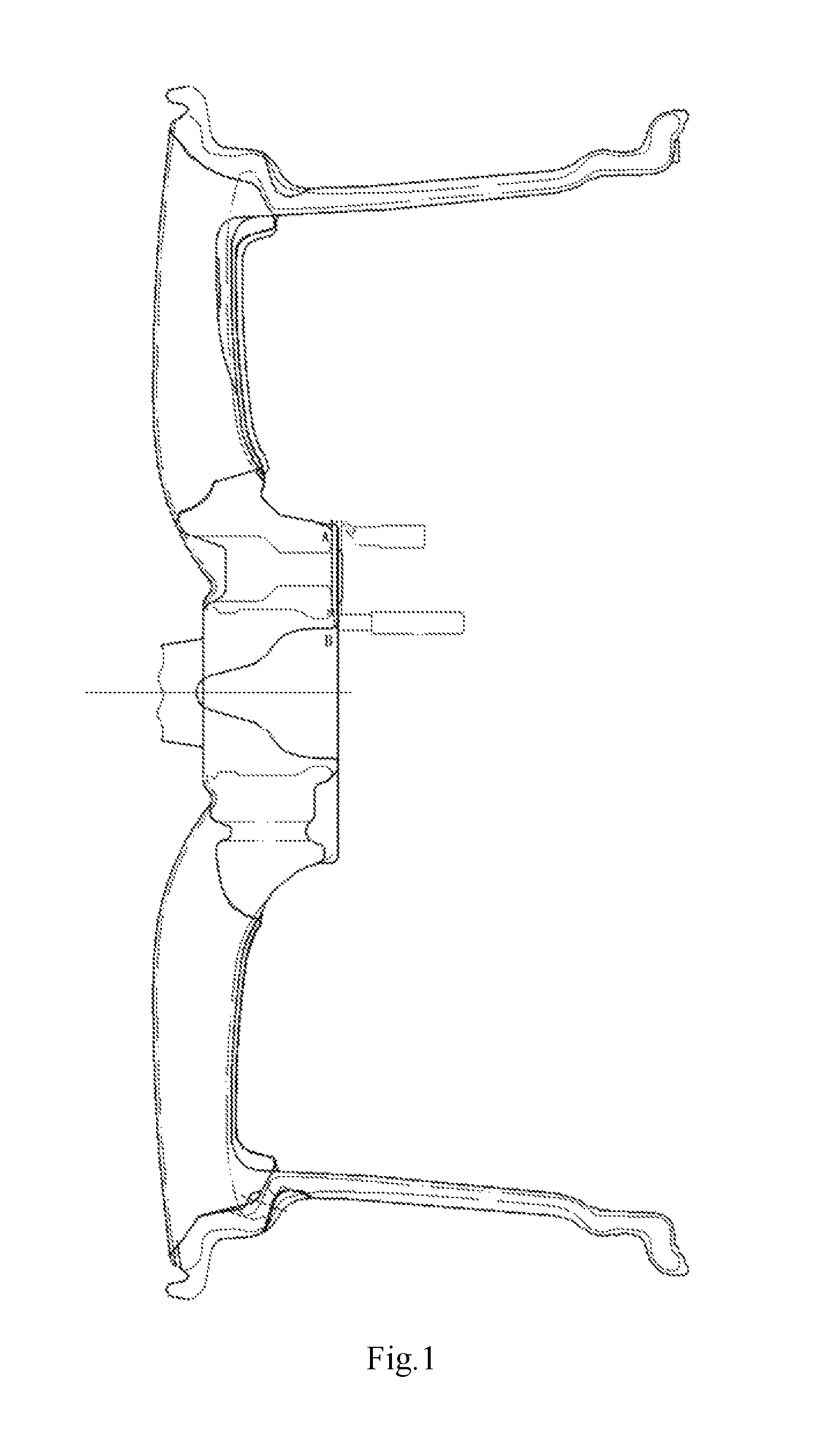
FIG. 1 is a schematic diagram of machining of a flange face in Embodiment 1;
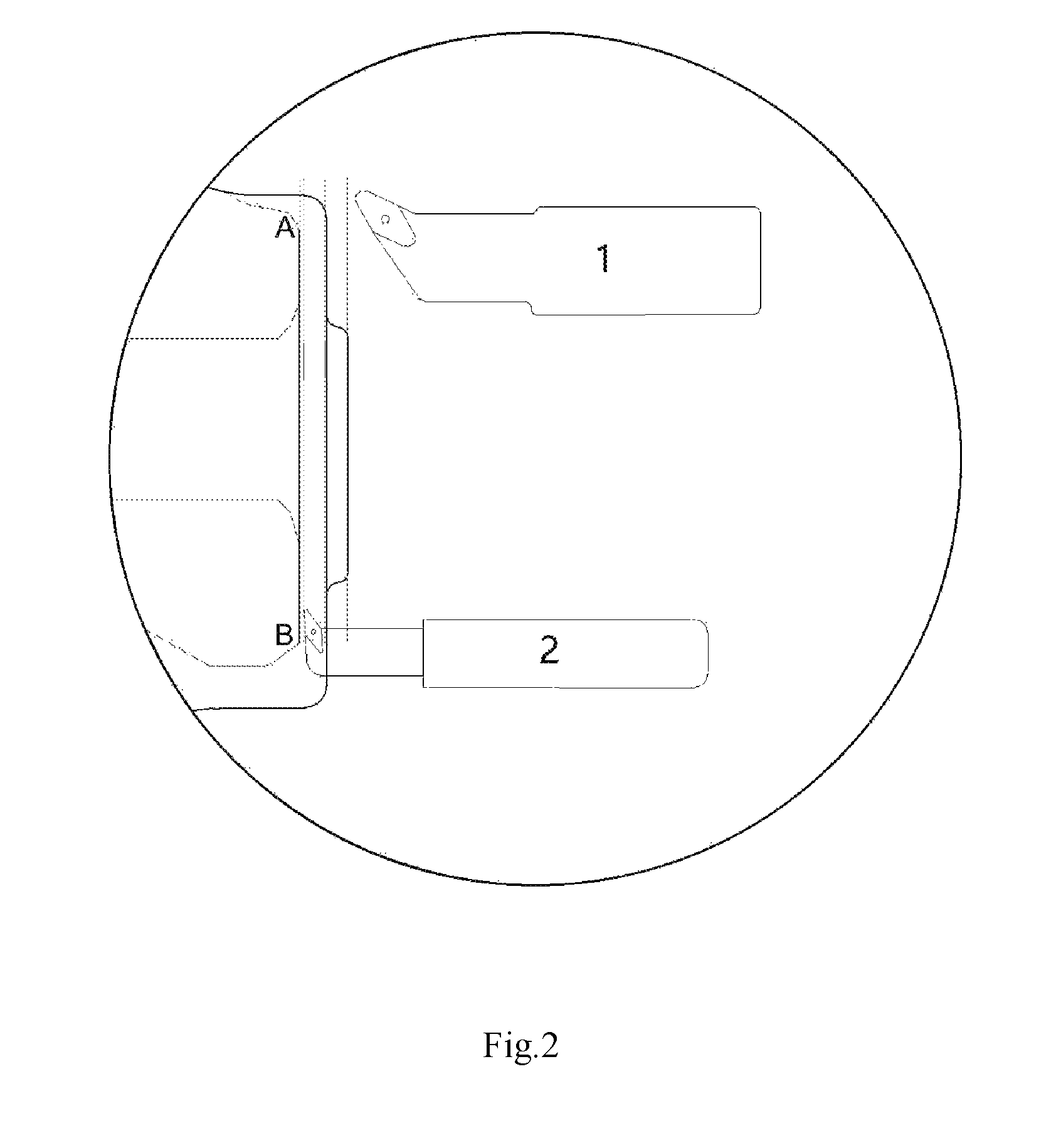
FIG. 2 is a partial enlarged view of machining of the flange face in Embodiment 1;
In which: A--inner side of the flange; B--outer side of the flange; 1-120.degree. R3 boring tool; 2-95.degree. R0.8 hook tool.
DETAILED DESCRIPTION OF THE INVENTION
The details and working conditions of the specific device proposed by the present application will be described below in combination with the accompanying drawings.
In the operation process, a wheel is clamped on a numerical control machine tool by a fixture. A motor drives a spindle of the machine tool to rotate, so that the wheel rotates counterclockwise at a certain speed. The blade is clamped horizontally on a turret together with a standard tool bar to machine a flange face at a certain feed rate in accordance with a pre-programmed machining program. According to the present application, the blank is maximally turned first using a 120.degree. R3 boring tool at a certain feed rate, a machining allowance of 0.4 mm is reserved, and then the remaining machining allowance is turned from B to A using a 95.degree. R0.8 hook tool at a certain feed rate.
Embodiment 1
A flange is turned four times, when a 120.degree. R3 boring tool is used for rough turning, the forward speed of the hub is set to 1200 r/min, the rough turning feed rate is 0.40 mm/r, and the turning amount is 1 mm each time; and when a 95.degree. hook tool is used for finish turning, the forward speed of the hub is set to 1200 r/min, the first finish turning feed rate is 0.15 mm/r and the turning amount is 0.35 mm, the second finish turning feed rate is 0.1 mm/r and the turning amount is 0.05 mm.
Embodiment 2
A flange is turned four times, when a 120.degree. R3 boring tool is used for rough turning, the forward speed of the hub is set to 1400 r/min, the rough turning feed rate is 0.45 mm/r, and the turning amount is 1 mm each time; and when a 95.degree. hook tool is used for finish turning, the forward speed of the hub is set to 1300 r/min, the first finish turning feed rate is 0.18 mm/r and the turning amount is 0.35 mm, the second finish turning feed rate is 0.11 mm/r and the turning amount is 0.05 mm.
Embodiment 3
A flange is turned four times, when a 120.degree. R3 boring tool is used for rough turning, the forward speed of the hub is set to 1500 r/min, the rough turning feed rate is 0.5 mm/r, and the turning amount is 1 mm each time; and when a 95.degree. hook tool is used for finish turning, the forward speed of the hub is set to 1500 r/min, the first finish turning feed rate is 0.2 mm/r and the turning amount is 0.35 mm, the second finish turning feed rate is 0.12 mm/r and the turning amount is 0.05 mm.
Embodiment 4
The planeness of the machined flanges of Embodiments 1-3 above and Comparative Example 1 is evaluated by using a three-coordinate instrument. 36 points are respectively selected from four groups of flange planes to measure their three-dimensional coordinates. Through the least squares plane fitting, the degree of regularity of each group of planes is investigated. The test shows that the planeness of Embodiments 1-3 is much higher than that of Comparative Example 1. It is believed that the progressive machining ensures a high standard of final machining accuracy.
In addition, it is also found that in the case of using different tools in steps II-V, after 150,000 hubs are machined, the replacement frequency of the hard alloy hook tool in step V is extremely low and reaches 7000 rounds once. The replacement frequency of the hard alloy hook tool in steps IV-V reaches 3,500 rounds once. Adding the both, the effective machining number of hubs is improved by more than 20% over the comparative example.
The foregoing descriptions of specific exemplary embodiments of the present invention have been presented for purposes of illustration and description. They are not intended to be exhaustive or to limit the invention to the precise forms disclosed, and obviously many modifications and variations are possible in light of the above teachings. The exemplary embodiments were chosen and described in order to explain certain principles of the invention and their practical application, to thereby enable others skilled in the art to make and utilize various exemplary embodiments of the present invention, as well as various alternatives and modifications thereof. It is intended that the scope of the invention be defined by the Claims appended hereto and their equivalents.
* * * * *
D00000
D00001
D00002
P00001
P00002
XML
uspto.report is an independent third-party trademark research tool that is not affiliated, endorsed, or sponsored by the United States Patent and Trademark Office (USPTO) or any other governmental organization. The information provided by uspto.report is based on publicly available data at the time of writing and is intended for informational purposes only.
While we strive to provide accurate and up-to-date information, we do not guarantee the accuracy, completeness, reliability, or suitability of the information displayed on this site. The use of this site is at your own risk. Any reliance you place on such information is therefore strictly at your own risk.
All official trademark data, including owner information, should be verified by visiting the official USPTO website at www.uspto.gov. This site is not intended to replace professional legal advice and should not be used as a substitute for consulting with a legal professional who is knowledgeable about trademark law.