Fastener applicator with interlock
Wheeler , et al. Nov
U.S. patent number 10,485,545 [Application Number 15/037,963] was granted by the patent office on 2019-11-26 for fastener applicator with interlock. This patent grant is currently assigned to DATASCOPE CORP.. The grantee listed for this patent is DATASCOPE CORP.. Invention is credited to Ashik A. Mohan, William K. Wheeler.
View All Diagrams
| United States Patent | 10,485,545 |
| Wheeler , et al. | November 26, 2019 |
Fastener applicator with interlock
Abstract
The present disclosure relates to a fastener applicator including a handle, a first trigger coupled rotatably with respect to the handle, and a second trigger coupled rotatably with respect to the handle. An interlock is disposed with the second trigger and comprises a cam follower engaged in a cam channel that selectively prevents rotation of the second trigger relative to the first trigger depending on a location of the cam follower within the cam channel. The location of the cam follower in the cam channel is set by a position of the first trigger. Methods of operating the various embodiments disclosed are also provided.
| Inventors: | Wheeler; William K. (Berthoud, CO), Mohan; Ashik A. (Petaluma, CA) | ||||||||||
|---|---|---|---|---|---|---|---|---|---|---|---|
| Applicant: |
|
||||||||||
| Assignee: | DATASCOPE CORP. (Mahwah,
NJ) |
||||||||||
| Family ID: | 53180100 | ||||||||||
| Appl. No.: | 15/037,963 | ||||||||||
| Filed: | November 19, 2014 | ||||||||||
| PCT Filed: | November 19, 2014 | ||||||||||
| PCT No.: | PCT/US2014/066438 | ||||||||||
| 371(c)(1),(2),(4) Date: | May 19, 2016 | ||||||||||
| PCT Pub. No.: | WO2015/077356 | ||||||||||
| PCT Pub. Date: | May 08, 2015 |
Prior Publication Data
| Document Identifier | Publication Date | |
|---|---|---|
| US 20160296233 A1 | Oct 13, 2016 | |
Related U.S. Patent Documents
| Application Number | Filing Date | Patent Number | Issue Date | ||
|---|---|---|---|---|---|
| 61906290 | Nov 19, 2013 | ||||
| Current U.S. Class: | 1/1 |
| Current CPC Class: | A61B 17/072 (20130101); A61B 17/083 (20130101); A61B 17/0643 (20130101); A61B 17/122 (20130101); A61B 17/1285 (20130101); A61B 17/10 (20130101); A61B 2017/00243 (20130101) |
| Current International Class: | A61B 17/10 (20060101); A61B 17/064 (20060101); A61B 17/072 (20060101); A61B 17/08 (20060101); A61B 17/122 (20060101); A61B 17/128 (20060101); A61B 17/00 (20060101) |
References Cited [Referenced By]
U.S. Patent Documents
| 729116 | May 1903 | Barnstead |
| 1756670 | April 1930 | Treat |
| 2659371 | November 1953 | Schnee |
| 3139563 | June 1964 | Cosgrove, III et al. |
| 3361133 | January 1968 | Kimberley et al. |
| 3525340 | August 1970 | Gilbert et al. |
| 3746002 | July 1973 | Haller |
| 3993076 | November 1976 | Fogarty |
| 4016883 | April 1977 | Wright, Jr. |
| 4060089 | November 1977 | Noiles |
| 4241861 | December 1980 | Fleischer |
| 4257419 | March 1981 | Goltner et al. |
| 4271828 | June 1981 | Angelchik |
| 4390019 | June 1983 | LeVeen et al. |
| 4402445 | September 1983 | Green |
| 4414721 | November 1983 | Hufnagel |
| 4487205 | December 1984 | Di Giovanni et al. |
| 4489725 | December 1984 | Casey et al. |
| 4506670 | March 1985 | Crossley |
| 4506671 | March 1985 | Green |
| 4548201 | October 1985 | Yoon |
| 4610250 | September 1986 | Green |
| 4702247 | October 1987 | Blake et al. |
| 4724839 | February 1988 | Bedi et al. |
| 4754758 | July 1988 | Li |
| 4805617 | February 1989 | Bedi et al. |
| 4822348 | April 1989 | Casey |
| 4924864 | May 1990 | Danzig |
| 4960420 | October 1990 | Goble et al. |
| 4976722 | December 1990 | Failla |
| 4988355 | January 1991 | Leveen et al. |
| 5002552 | March 1991 | Casey |
| 5062846 | November 1991 | Oh et al. |
| 5094753 | March 1992 | Allington et al. |
| 5127915 | July 1992 | Mattson |
| 5132014 | July 1992 | Allington et al. |
| 5156315 | October 1992 | Green et al. |
| 5156614 | October 1992 | Green et al. |
| 5160339 | November 1992 | Chen et al. |
| 5160624 | November 1992 | Clay et al. |
| 5171247 | December 1992 | Hughett et al. |
| 5171249 | December 1992 | Stefanchik et al. |
| 5171253 | December 1992 | Klieman |
| 5173188 | December 1992 | Winter et al. |
| 5193554 | March 1993 | McQuilkin |
| 5198197 | March 1993 | Clay et al. |
| 5207691 | May 1993 | Nardella |
| 5246456 | September 1993 | Wilkinson |
| 5250195 | October 1993 | Winter et al. |
| 5253793 | October 1993 | Green et al. |
| 5257999 | November 1993 | Slanetz, Jr. |
| 5268102 | December 1993 | Clay et al. |
| 5268103 | December 1993 | Jameson et al. |
| 5269930 | December 1993 | Jameson |
| 5282812 | February 1994 | Suarez, Jr. |
| 5296145 | March 1994 | Allington et al. |
| 5306234 | April 1994 | Johnson |
| 5336232 | August 1994 | Green et al. |
| 5352238 | October 1994 | Green et al. |
| 5358506 | October 1994 | Green et al. |
| 5358510 | October 1994 | Luscombe et al. |
| 5366458 | November 1994 | Korthoff et al. |
| 5366459 | November 1994 | Yoon |
| 5368600 | November 1994 | Failla et al. |
| 5379933 | January 1995 | Green et al. |
| 5413268 | May 1995 | Green et al. |
| 5423471 | June 1995 | Mastri et al. |
| 5425705 | June 1995 | Evard et al. |
| 5425740 | June 1995 | Hutchinson, Jr. |
| 5441507 | August 1995 | Wilk |
| 5462215 | October 1995 | Viola et al. |
| 5462558 | October 1995 | Kolesa et al. |
| 5465895 | November 1995 | Knodel |
| 5470006 | November 1995 | Rodak |
| 5470009 | November 1995 | Rodak |
| 5474567 | December 1995 | Stefanchik et al. |
| 5485947 | January 1996 | Olson et al. |
| 5490856 | February 1996 | Person et al. |
| 5501693 | March 1996 | Gravener |
| 5507797 | April 1996 | Suzuki et al. |
| 5509920 | April 1996 | Phillips et al. |
| 5531744 | July 1996 | Nardella et al. |
| 5536251 | July 1996 | Evard |
| 5547117 | August 1996 | Hamblin et al. |
| 5549621 | August 1996 | Bessler et al. |
| 5551622 | September 1996 | Yoon |
| 5554169 | September 1996 | Green et al. |
| 5560530 | October 1996 | Bolanos et al. |
| 5569272 | October 1996 | Reed et al. |
| 5573169 | November 1996 | Green et al. |
| 5575802 | November 1996 | McQuilkin et al. |
| 5580067 | December 1996 | Hamblin et al. |
| 5584989 | December 1996 | Jameson |
| 5591178 | January 1997 | Green et al. |
| 5597107 | January 1997 | Knodel et al. |
| 5601573 | February 1997 | Fogelberg et al. |
| 5601707 | February 1997 | Clay et al. |
| 5605272 | February 1997 | Witt et al. |
| 5605273 | February 1997 | Hamblin et al. |
| 5614089 | March 1997 | Allington et al. |
| 5620452 | April 1997 | Yoon |
| 5624453 | April 1997 | Ahmed |
| 5626592 | May 1997 | Phillips et al. |
| 5632432 | May 1997 | Schulze et al. |
| 5635070 | June 1997 | Allington et al. |
| 5643291 | July 1997 | Pier et al. |
| 5643319 | July 1997 | Green et al. |
| 5645553 | July 1997 | Kolesa et al. |
| 5653373 | August 1997 | Green et al. |
| 5653885 | August 1997 | Jameson et al. |
| 5655698 | August 1997 | Yoon |
| 5658300 | August 1997 | Bito et al. |
| 5662259 | September 1997 | Yoon |
| 5662260 | September 1997 | Yoon |
| 5665085 | September 1997 | Nardella |
| 5669544 | September 1997 | Schulze |
| 5676676 | October 1997 | Porter |
| 5690828 | November 1997 | Clay et al. |
| 5695502 | December 1997 | Pier et al. |
| 5697938 | December 1997 | Jensen et al. |
| 5706998 | January 1998 | Plyley et al. |
| 5713896 | February 1998 | Nardella |
| 5713912 | February 1998 | Porter |
| 5715987 | February 1998 | Kelley et al. |
| 5720756 | February 1998 | Green et al. |
| 5722982 | March 1998 | Ferreira et al. |
| 5725537 | March 1998 | Green et al. |
| 5725538 | March 1998 | Green et al. |
| 5728110 | March 1998 | Vidal et al. |
| 5735874 | April 1998 | Measamer et al. |
| 5738498 | April 1998 | Allington et al. |
| 5741283 | April 1998 | Fahy |
| 5749893 | May 1998 | Vidal et al. |
| 5750027 | May 1998 | Allington et al. |
| 5755559 | May 1998 | Allington et al. |
| 5755726 | May 1998 | Pratt et al. |
| 5759193 | June 1998 | Burbank et al. |
| 5772673 | June 1998 | Cuny et al. |
| 5779718 | July 1998 | Green et al. |
| 5794834 | August 1998 | Hamblin et al. |
| 5797932 | August 1998 | Min et al. |
| 5833695 | November 1998 | Yoon |
| 5833698 | November 1998 | Hinchliffe et al. |
| 5833700 | November 1998 | Fogelberg et al. |
| 5843101 | December 1998 | Fry |
| 5846255 | December 1998 | Casey |
| 5849019 | December 1998 | Yoon |
| 5855311 | January 1999 | Hamblin et al. |
| 5865791 | February 1999 | Whayne et al. |
| 5868761 | February 1999 | Nicholas et al. |
| 5893879 | April 1999 | Hirshowitz et al. |
| 5911881 | June 1999 | Clay et al. |
| 5915615 | June 1999 | Bauer |
| 5921997 | July 1999 | Fogelberg et al. |
| 5932095 | August 1999 | Walters et al. |
| 5964774 | October 1999 | McKean et al. |
| 5972022 | October 1999 | Huxel |
| 5976159 | November 1999 | Bolduc et al. |
| 6015417 | January 2000 | Reynolds, Jr. |
| 6036706 | March 2000 | Morejohn et al. |
| 6042599 | March 2000 | Huttner et al. |
| 6051003 | April 2000 | Chu et al. |
| 6071408 | June 2000 | Allington et al. |
| 6083399 | July 2000 | Jameson et al. |
| 6086767 | July 2000 | Walters et al. |
| 6139555 | October 2000 | Hart et al. |
| 6149814 | November 2000 | Allington et al. |
| 6152144 | November 2000 | Lesh et al. |
| 6162239 | December 2000 | Manhes |
| 6206897 | March 2001 | Jamiolkowski et al. |
| 6231561 | May 2001 | Frazier et al. |
| 6238414 | May 2001 | Griffiths |
| 6241890 | June 2001 | Clay et al. |
| 6251267 | June 2001 | Allington et al. |
| 6273897 | August 2001 | Dalessandro et al. |
| 6280407 | August 2001 | Manna et al. |
| 6290674 | September 2001 | Roue et al. |
| 6294088 | September 2001 | Allington et al. |
| 6296769 | October 2001 | Walters et al. |
| 6319410 | November 2001 | Allington et al. |
| 6325810 | December 2001 | Hamilton et al. |
| 6328727 | December 2001 | Frazier et al. |
| 6332864 | December 2001 | Schweich et al. |
| 6338710 | January 2002 | Takahashi et al. |
| 6379366 | April 2002 | Fleischman et al. |
| 6387106 | May 2002 | Howell et al. |
| 6391038 | May 2002 | Vargas et al. |
| 6406485 | June 2002 | Hossain et al. |
| 6419669 | July 2002 | Frazier et al. |
| 6419682 | July 2002 | Appleby et al. |
| 6421920 | July 2002 | Jensen |
| RE37814 | August 2002 | Allgeyer |
| 6436097 | August 2002 | Nardella |
| 6436108 | August 2002 | Mears |
| 6458100 | October 2002 | Roue et al. |
| 6461363 | October 2002 | Gadberry et al. |
| 6461368 | October 2002 | Fogarty et al. |
| 6478804 | November 2002 | Vargas et al. |
| 6488689 | December 2002 | Kaplan et al. |
| 6503259 | January 2003 | Huxel et al. |
| 6508829 | January 2003 | Levinson et al. |
| 6517556 | February 2003 | Monassevitch |
| 6520972 | February 2003 | Peters |
| 6527786 | March 2003 | Davis et al. |
| 6551303 | April 2003 | Van Tassel et al. |
| 6558408 | May 2003 | Fogarty et al. |
| 6561969 | May 2003 | Frazier et al. |
| 6579304 | June 2003 | Hart et al. |
| 6582451 | June 2003 | Marucci et al. |
| 6592600 | July 2003 | Nicolo |
| 6629988 | October 2003 | Weadock |
| 6638282 | October 2003 | Ramsey et al. |
| 6641557 | November 2003 | Frazier et al. |
| 6644618 | November 2003 | Balbo |
| 6652555 | November 2003 | VanTassel et al. |
| 6652556 | November 2003 | VanTassel et al. |
| 6656205 | December 2003 | Manhes |
| 6663653 | December 2003 | Akerfeldt |
| 6685715 | February 2004 | Danitz et al. |
| 6689150 | February 2004 | VanTassel et al. |
| 6692507 | February 2004 | Pugsley et al. |
| 6699258 | March 2004 | Sadler et al. |
| 6702825 | March 2004 | Frazier et al. |
| 6702826 | March 2004 | Liddicoat et al. |
| 6712804 | March 2004 | Roue et al. |
| 6716232 | April 2004 | Vidal et al. |
| 6723109 | April 2004 | Solingen |
| 6730108 | May 2004 | Van Tassel et al. |
| 6746461 | June 2004 | Fry |
| 6746472 | June 2004 | Frazier et al. |
| 6755338 | June 2004 | Hahnen et al. |
| 6776783 | August 2004 | Frantzen et al. |
| 6776785 | August 2004 | Yencho et al. |
| 6780195 | August 2004 | Porat |
| 6790172 | September 2004 | Alferness et al. |
| 6817972 | November 2004 | Snow |
| 6821285 | November 2004 | Laufer et al. |
| 6830174 | December 2004 | Hillstead et al. |
| 6840246 | January 2005 | Downing |
| 6863675 | March 2005 | Wilson, Jr. |
| 6893391 | May 2005 | Taylor |
| 6916332 | July 2005 | Adams |
| 6926712 | August 2005 | Phan |
| 6949113 | September 2005 | Van Tassel et al. |
| 6974462 | December 2005 | Sater |
| 6994092 | February 2006 | van der Burg et al. |
| 7001412 | February 2006 | Gallagher et al. |
| 7033378 | April 2006 | Smith et al. |
| 7044134 | May 2006 | Khairkhahan et al. |
| 7070083 | July 2006 | Jankowski |
| 7077856 | July 2006 | Whitman |
| 7083636 | August 2006 | Kortenbach |
| 7108703 | September 2006 | Danitz et al. |
| 7128073 | October 2006 | van der Burg et al. |
| 7152605 | December 2006 | Khairkhahan et al. |
| 7220272 | May 2007 | Weadock |
| 7226458 | June 2007 | Kaplan et al. |
| 7285131 | October 2007 | Bombard et al. |
| 7300444 | November 2007 | Nielsen et al. |
| 7316696 | January 2008 | Wilson et al. |
| 7326223 | February 2008 | Wilson, Jr. |
| 7407076 | August 2008 | Racenet et al. |
| 7422783 | September 2008 | Tremblay et al. |
| 7427279 | September 2008 | Frazier et al. |
| 7438208 | October 2008 | Larson |
| 7438718 | October 2008 | Milliman et al. |
| 7473258 | January 2009 | Clauson et al. |
| 7473261 | January 2009 | Rennich |
| 7497865 | March 2009 | Willis et al. |
| 7503474 | March 2009 | Hillstead et al. |
| 7527634 | May 2009 | Zenati et al. |
| 7543730 | June 2009 | Marczyk |
| 7547315 | June 2009 | Peterson et al. |
| 7549983 | June 2009 | Roue et al. |
| 7553315 | June 2009 | Kortenbach |
| 7556185 | July 2009 | Viola |
| 7563267 | July 2009 | Goldfarb et al. |
| 7569064 | August 2009 | Hausen et al. |
| 7628797 | December 2009 | Tieu et al. |
| 7635073 | December 2009 | Heinrich |
| 7645285 | January 2010 | Cosgrove et al. |
| 7648514 | January 2010 | Nakao |
| 7658311 | February 2010 | Boudreaux |
| 7658312 | February 2010 | Vidal et al. |
| 7665646 | February 2010 | Prommersberger |
| 7673782 | March 2010 | Hess et al. |
| 7681772 | March 2010 | Green et al. |
| 7686200 | March 2010 | Peterson |
| 7686759 | March 2010 | Sater |
| 7686820 | March 2010 | Huitema et al. |
| 7699860 | April 2010 | Huitema et al. |
| 7713276 | May 2010 | Dennis |
| 7717312 | May 2010 | Beetel |
| 7717937 | May 2010 | Wahr et al. |
| 7722527 | May 2010 | Bouchier et al. |
| 7722628 | May 2010 | Stokes et al. |
| 7722641 | May 2010 | van der Burg et al. |
| 7722643 | May 2010 | Schaller et al. |
| 7727142 | June 2010 | Hjelle et al. |
| 7727189 | June 2010 | VanTassel et al. |
| 7731073 | June 2010 | Wixey et al. |
| 7735493 | June 2010 | van der Burg et al. |
| 7735703 | June 2010 | Morgan et al. |
| 7740159 | June 2010 | Shelton et al. |
| 7749249 | July 2010 | Gelbart et al. |
| 7753245 | July 2010 | Boudreaux et al. |
| 7753248 | July 2010 | Viola |
| 7757924 | July 2010 | Gerbi et al. |
| 7758610 | July 2010 | Kanner et al. |
| 7766207 | August 2010 | Mather et al. |
| 7766924 | August 2010 | Bombard et al. |
| 7770774 | August 2010 | Mastri et al. |
| 7780683 | August 2010 | Roue et al. |
| 7780685 | August 2010 | Hunt et al. |
| 7794475 | September 2010 | Hess et al. |
| 7819886 | October 2010 | Whitfield et al. |
| 7828188 | November 2010 | Jankowski |
| 7828810 | November 2010 | Liddicoat et al. |
| 7845533 | December 2010 | Marczyk et al. |
| 7845588 | December 2010 | Goodick |
| 7846168 | December 2010 | Liddicoat et al. |
| 7862571 | January 2011 | Dennis |
| 7866523 | January 2011 | White et al. |
| 7891534 | February 2011 | Wenchell et al. |
| 7892244 | February 2011 | Monassevitch et al. |
| 7896895 | March 2011 | Boudreaux et al. |
| 7896896 | March 2011 | Viola |
| 7909224 | March 2011 | Prommersberger |
| 7913893 | March 2011 | Mastri et al. |
| 7926691 | April 2011 | Viola et al. |
| 7931578 | April 2011 | Whayne et al. |
| 7950561 | May 2011 | Aranyi |
| 7951069 | May 2011 | Bertolero |
| 7951147 | May 2011 | Privitera et al. |
| 7954686 | June 2011 | Baxter et al. |
| 7959051 | June 2011 | Smith |
| 7959555 | June 2011 | Dietz et al. |
| 7967178 | June 2011 | Scirica et al. |
| 7967180 | June 2011 | Scirica |
| 7992757 | August 2011 | Wheeler et al. |
| 8002795 | August 2011 | Beetel |
| 8007504 | August 2011 | Zenati et al. |
| 8011553 | September 2011 | Mastri et al. |
| 8016177 | September 2011 | Bettuchi et al. |
| 8021378 | September 2011 | Sixto et al. |
| 8028884 | October 2011 | Sniffin et al. |
| 8033439 | October 2011 | Racenet et al. |
| 8038045 | October 2011 | Bettuchi et al. |
| 8043328 | October 2011 | Hahnen et al. |
| 8056787 | November 2011 | Boudreaux |
| 8066168 | November 2011 | Vidal et al. |
| 8066721 | November 2011 | Kortenbach et al. |
| 8070033 | December 2011 | Milliman et al. |
| 8070035 | December 2011 | Holsten et al. |
| 8070038 | December 2011 | Kostrzewski |
| 8074861 | December 2011 | Ehrenfels et al. |
| 8074862 | December 2011 | Shah |
| 8080020 | December 2011 | Kortenbach et al. |
| 8080032 | December 2011 | van der Burg et al. |
| 8083118 | December 2011 | Milliman et al. |
| 8083119 | December 2011 | Prommersberger |
| 8091753 | January 2012 | Viola |
| 8091756 | January 2012 | Viola |
| 8096459 | January 2012 | Ortiz et al. |
| 8113405 | February 2012 | Milliman |
| 8113406 | February 2012 | Holsten et al. |
| 8113407 | February 2012 | Holsten et al. |
| 8113408 | February 2012 | Wenchell et al. |
| 8114123 | February 2012 | Brenzel et al. |
| 8118207 | February 2012 | Racenet et al. |
| 8123101 | February 2012 | Racenet et al. |
| 8128642 | March 2012 | Heeps et al. |
| 8152041 | April 2012 | Kostrzewski |
| 8152823 | April 2012 | Kassab et al. |
| 8157149 | April 2012 | Olson et al. |
| 8157152 | April 2012 | Holsten et al. |
| 8162197 | April 2012 | Mastri et al. |
| 8172122 | May 2012 | Kasvikis et al. |
| 8181837 | May 2012 | Roy |
| 8186558 | May 2012 | Sapienza |
| 8187286 | May 2012 | Jugenheimer et al. |
| 8191752 | June 2012 | Scirica |
| 8192460 | June 2012 | Orban et al. |
| 8196796 | June 2012 | Shelton et al. |
| 8205620 | June 2012 | Taylor et al. |
| 8205780 | June 2012 | Sorrentino et al. |
| 8205781 | June 2012 | Baxter et al. |
| 8210412 | July 2012 | Marczyk |
| 8210413 | July 2012 | Whitman et al. |
| 8210414 | July 2012 | Bettuchi et al. |
| 8210416 | July 2012 | Milliman et al. |
| 8215532 | July 2012 | Marczyk |
| 8220690 | July 2012 | Hess et al. |
| 8221445 | July 2012 | van Tassel et al. |
| 8225980 | July 2012 | Rivera |
| 8231040 | July 2012 | Zemlok et al. |
| 8235272 | August 2012 | Nicholas et al. |
| 8235274 | August 2012 | Cappola |
| 8236015 | August 2012 | Bettuchi et al. |
| 8240536 | August 2012 | Marczyk |
| 8240537 | August 2012 | Marczyk |
| 8241322 | August 2012 | Whitman et al. |
| 8245900 | August 2012 | Scirica |
| 8245901 | August 2012 | Stopek |
| 8246634 | August 2012 | Huitema et al. |
| 8256654 | September 2012 | Bettuchi et al. |
| 8256655 | September 2012 | Sniffin et al. |
| 8256656 | September 2012 | Milliman et al. |
| 8267849 | September 2012 | Wazer et al. |
| 8272552 | September 2012 | Holsten et al. |
| 8272553 | September 2012 | Mastri et al. |
| 8272554 | September 2012 | Whitman et al. |
| 8276594 | October 2012 | Shah |
| 8276800 | October 2012 | Bettuchi |
| 8276801 | October 2012 | Zemlok et al. |
| 8276802 | October 2012 | Kostrzewski |
| 8281973 | October 2012 | Wenchell et al. |
| 8281974 | October 2012 | Hessler et al. |
| 8281975 | October 2012 | Criscuolo et al. |
| 8286847 | October 2012 | Taylor |
| 8286848 | October 2012 | Wenchell et al. |
| 8287563 | October 2012 | Khairkhahan et al. |
| 8292146 | October 2012 | Holsten et al. |
| 8292147 | October 2012 | Viola |
| 8292148 | October 2012 | Viola |
| 8292149 | October 2012 | Ivanko |
| 8292150 | October 2012 | Bryant |
| 8292151 | October 2012 | Viola |
| 8292152 | October 2012 | Milliman et al. |
| 8292153 | October 2012 | Jankowski |
| 8292154 | October 2012 | Marczyk |
| 8292155 | October 2012 | Shelton et al. |
| 8292156 | October 2012 | Kostrzewski |
| 8292158 | October 2012 | Sapienza |
| 8403197 | March 2013 | Vidal et al. |
| 8561872 | October 2013 | Wheeler et al. |
| 8647350 | February 2014 | Mohan et al. |
| 8685055 | April 2014 | VanTassel et al. |
| 9072536 | July 2015 | Shelton, IV |
| 9232941 | January 2016 | Mandakolathur Vasudevan |
| 9289211 | March 2016 | Williams |
| 9375218 | June 2016 | Wheeler et al. |
| 9861359 | January 2018 | Shelton, IV |
| 2001/0005787 | June 2001 | Oz et al. |
| 2001/0014811 | August 2001 | Hussein |
| 2001/0016748 | August 2001 | Tanner et al. |
| 2001/0034536 | October 2001 | Looper et al. |
| 2001/0039423 | November 2001 | Skiba et al. |
| 2001/0041914 | November 2001 | Frazier et al. |
| 2002/0022880 | February 2002 | Melvin |
| 2002/0032454 | March 2002 | Durgin et al. |
| 2002/0047035 | April 2002 | Coleman et al. |
| 2002/0049457 | April 2002 | Kaplan et al. |
| 2002/0055750 | May 2002 | Durgin et al. |
| 2002/0065535 | May 2002 | Kneifel et al. |
| 2002/0068945 | June 2002 | Sixto et al. |
| 2002/0072759 | June 2002 | Fry |
| 2002/0082621 | June 2002 | Schurr et al. |
| 2002/0103492 | August 2002 | Kaplan et al. |
| 2002/0111637 | August 2002 | Kaplan et al. |
| 2002/0120281 | August 2002 | Overaker |
| 2002/0138086 | September 2002 | Sixto et al. |
| 2002/0151889 | October 2002 | Swanson et al. |
| 2002/0173848 | November 2002 | Sachs |
| 2002/0177863 | November 2002 | Mandel et al. |
| 2002/0183770 | December 2002 | Anderson |
| 2002/0183771 | December 2002 | Burbank et al. |
| 2002/0183785 | December 2002 | Howell et al. |
| 2002/0198549 | December 2002 | Sixto et al. |
| 2003/0065340 | April 2003 | Geitz |
| 2003/0078603 | April 2003 | Schaller et al. |
| 2003/0114865 | June 2003 | Sater |
| 2003/0120337 | June 2003 | Van Tassel et al. |
| 2003/0125729 | July 2003 | Hooven et al. |
| 2003/0125755 | July 2003 | Schaller et al. |
| 2003/0130670 | July 2003 | Anderson et al. |
| 2003/0153930 | August 2003 | De Canniere |
| 2003/0158464 | August 2003 | Bertolero |
| 2003/0158604 | August 2003 | Cauthen et al. |
| 2003/0181929 | September 2003 | Geitz |
| 2003/0191479 | October 2003 | Thornton |
| 2003/0191494 | October 2003 | Gray et al. |
| 2003/0191526 | October 2003 | Van Tassel et al. |
| 2003/0195531 | October 2003 | Gardiner et al. |
| 2003/0216757 | November 2003 | Gerberding |
| 2003/0220660 | November 2003 | Kortenbach et al. |
| 2003/0220667 | November 2003 | van der Burg et al. |
| 2003/0225421 | December 2003 | Peavey et al. |
| 2003/0225423 | December 2003 | Huitema |
| 2003/0225424 | December 2003 | Benderev |
| 2003/0229367 | December 2003 | Viola |
| 2003/0233095 | December 2003 | Urbanski et al. |
| 2003/0236537 | December 2003 | Hart et al. |
| 2004/0006353 | January 2004 | Bosley et al. |
| 2004/0024414 | February 2004 | Downing |
| 2004/0030335 | February 2004 | Zenati et al. |
| 2004/0034375 | February 2004 | Ruiz et al. |
| 2004/0049210 | March 2004 | VanTassel et al. |
| 2004/0059354 | March 2004 | Smith et al. |
| 2004/0059359 | March 2004 | Wilson, Jr. |
| 2004/0073234 | April 2004 | Chu et al. |
| 2004/0073241 | April 2004 | Barry et al. |
| 2004/0089312 | May 2004 | Jordan |
| 2004/0092973 | May 2004 | Chanduszko et al. |
| 2004/0093024 | May 2004 | Lousararian et al. |
| 2004/0097980 | May 2004 | Ferree |
| 2004/0097982 | May 2004 | Jugenheimer et al. |
| 2004/0111100 | June 2004 | Benderev et al. |
| 2004/0116948 | June 2004 | Sixto et al. |
| 2004/0122456 | June 2004 | Saadat et al. |
| 2004/0122467 | June 2004 | VanTassel et al. |
| 2004/0127919 | July 2004 | Trout et al. |
| 2004/0127935 | July 2004 | VanTassel et al. |
| 2004/0133214 | July 2004 | Kayan |
| 2004/0133215 | July 2004 | Baxter |
| 2004/0133219 | July 2004 | Forsell |
| 2004/0138683 | July 2004 | Shelton et al. |
| 2004/0186486 | September 2004 | Roue et al. |
| 2004/0193188 | September 2004 | Francese |
| 2004/0199178 | October 2004 | Small |
| 2004/0230222 | November 2004 | van der Burg et al. |
| 2005/0004652 | January 2005 | van der Burg et al. |
| 2005/0021061 | January 2005 | Dennis |
| 2005/0021062 | January 2005 | Dennis |
| 2005/0027308 | February 2005 | Davis et al. |
| 2005/0049573 | March 2005 | Van Tassel et al. |
| 2005/0059988 | March 2005 | Danitz et al. |
| 2005/0125010 | June 2005 | Smith et al. |
| 2005/0139635 | June 2005 | Wukusick |
| 2005/0143767 | June 2005 | Kimura et al. |
| 2005/0146069 | July 2005 | Kanan |
| 2005/0149068 | July 2005 | Williams et al. |
| 2005/0149069 | July 2005 | Bertolero et al. |
| 2005/0149988 | July 2005 | Grannan |
| 2005/0149989 | July 2005 | Lupoi et al. |
| 2005/0154404 | July 2005 | Liddicoat et al. |
| 2005/0165421 | July 2005 | Wilson et al. |
| 2005/0165422 | July 2005 | Wilson |
| 2005/0165423 | July 2005 | Gallagher et al. |
| 2005/0165424 | July 2005 | Gallagher et al. |
| 2005/0171560 | August 2005 | Hughett |
| 2005/0177180 | August 2005 | Kaganov et al. |
| 2005/0177182 | August 2005 | van der Burg et al. |
| 2005/0177224 | August 2005 | Fogarty et al. |
| 2005/0177232 | August 2005 | Ashton |
| 2005/0187569 | August 2005 | Dahl et al. |
| 2005/0251184 | November 2005 | Anderson |
| 2005/0273122 | December 2005 | Theroux et al. |
| 2005/0277955 | December 2005 | Palmer et al. |
| 2005/0277959 | December 2005 | Cosgrove et al. |
| 2006/0004388 | January 2006 | Whayne et al. |
| 2006/0004390 | January 2006 | Rosenberg et al. |
| 2006/0020162 | January 2006 | Whayne et al. |
| 2006/0020271 | January 2006 | Stewart et al. |
| 2006/0020275 | January 2006 | Goldfarb et al. |
| 2006/0025812 | February 2006 | Shelton |
| 2006/0100644 | May 2006 | Viola |
| 2006/0100649 | May 2006 | Hart |
| 2006/0111735 | May 2006 | Crainich |
| 2006/0151567 | July 2006 | Roy |
| 2006/0217749 | September 2006 | Wilson et al. |
| 2006/0264979 | November 2006 | Shepard |
| 2006/0264987 | November 2006 | Sgro |
| 2007/0005108 | January 2007 | Simhon et al. |
| 2007/0016228 | January 2007 | Salas |
| 2007/0060951 | March 2007 | Shannon |
| 2007/0073274 | March 2007 | Chin et al. |
| 2007/0083218 | April 2007 | A. Morris |
| 2007/0083227 | April 2007 | van der Burg et al. |
| 2007/0106314 | May 2007 | Dunn |
| 2007/0112365 | May 2007 | Hilal et al. |
| 2007/0118161 | May 2007 | Kennedy et al. |
| 2007/0118163 | May 2007 | Boudreaux et al. |
| 2007/0135826 | June 2007 | Zaver et al. |
| 2007/0149988 | June 2007 | Michler et al. |
| 2007/0149989 | June 2007 | Santilli et al. |
| 2007/0149995 | June 2007 | Quinn et al. |
| 2007/0162060 | July 2007 | Wild |
| 2007/0167964 | July 2007 | Willis |
| 2007/0179512 | August 2007 | Olsen et al. |
| 2007/0185506 | August 2007 | Jackson |
| 2007/0191868 | August 2007 | Theroux et al. |
| 2007/0203391 | August 2007 | Bloom et al. |
| 2007/0208357 | September 2007 | Houser et al. |
| 2007/0213747 | September 2007 | Monassevitch et al. |
| 2007/0246505 | October 2007 | Pace-Floridia et al. |
| 2007/0250086 | October 2007 | Wiley et al. |
| 2007/0260278 | November 2007 | Wheeler et al. |
| 2007/0265640 | November 2007 | Kortenbach et al. |
| 2007/0265641 | November 2007 | Roue et al. |
| 2007/0265642 | November 2007 | Chanduszko et al. |
| 2007/0270891 | November 2007 | McGuckin |
| 2007/0276417 | November 2007 | Mendes, Jr. et al. |
| 2008/0009866 | January 2008 | Alamin et al. |
| 2008/0021466 | January 2008 | Shadduck et al. |
| 2008/0021484 | January 2008 | Catanese et al. |
| 2008/0027471 | January 2008 | Hauri |
| 2008/0027478 | January 2008 | Connors et al. |
| 2008/0033241 | February 2008 | Peh et al. |
| 2008/0033457 | February 2008 | Francischelli et al. |
| 2008/0039879 | February 2008 | Chin et al. |
| 2008/0039922 | February 2008 | Miles et al. |
| 2008/0060658 | March 2008 | Doorschodt |
| 2008/0071294 | March 2008 | Bender et al. |
| 2008/0078800 | April 2008 | Hess et al. |
| 2008/0078802 | April 2008 | Hess et al. |
| 2008/0078803 | April 2008 | Shelton et al. |
| 2008/0078804 | April 2008 | Shelton et al. |
| 2008/0078806 | April 2008 | Omaits et al. |
| 2008/0078808 | April 2008 | Hess et al. |
| 2008/0097571 | April 2008 | Denison et al. |
| 2008/0105265 | May 2008 | Pannell et al. |
| 2008/0125795 | May 2008 | Kaplan et al. |
| 2008/0125796 | May 2008 | Graham |
| 2008/0132891 | June 2008 | Nobis et al. |
| 2008/0140095 | June 2008 | Smith et al. |
| 2008/0147083 | June 2008 | Vold et al. |
| 2008/0177292 | July 2008 | Jacobs et al. |
| 2008/0183283 | July 2008 | Downing |
| 2008/0208324 | August 2008 | Glithero et al. |
| 2008/0215090 | September 2008 | Gonzales et al. |
| 2008/0234785 | September 2008 | Nakayama et al. |
| 2008/0249547 | October 2008 | Dunn |
| 2008/0269787 | October 2008 | Laufer |
| 2008/0287989 | November 2008 | Weisel et al. |
| 2008/0294179 | November 2008 | Balbierz et al. |
| 2008/0300686 | December 2008 | Khoo |
| 2008/0312670 | December 2008 | Lutze et al. |
| 2008/0314961 | December 2008 | Boudreaux et al. |
| 2008/0319456 | December 2008 | Hart |
| 2009/0001121 | January 2009 | Hess et al. |
| 2009/0001124 | January 2009 | Hess et al. |
| 2009/0005808 | January 2009 | Hess et al. |
| 2009/0012545 | January 2009 | Williamson et al. |
| 2009/0020584 | January 2009 | Soltz et al. |
| 2009/0048665 | February 2009 | Miron et al. |
| 2009/0054916 | February 2009 | Meier et al. |
| 2009/0088783 | April 2009 | Kennedy et al. |
| 2009/0093826 | April 2009 | Warder-Gabaldon |
| 2009/0105731 | April 2009 | Priewe |
| 2009/0112249 | April 2009 | Miles et al. |
| 2009/0118748 | May 2009 | Pugsley et al. |
| 2009/0131959 | May 2009 | Rolland |
| 2009/0138028 | May 2009 | Wells et al. |
| 2009/0163937 | June 2009 | Kassab et al. |
| 2009/0171380 | July 2009 | Whiting |
| 2009/0171386 | July 2009 | Amplatz et al. |
| 2009/0177212 | July 2009 | Carley et al. |
| 2009/0182326 | July 2009 | Zenati et al. |
| 2009/0182374 | July 2009 | Keith |
| 2009/0182419 | July 2009 | Bolling |
| 2009/0187198 | July 2009 | Weitzner |
| 2009/0206127 | August 2009 | Danielson et al. |
| 2009/0209986 | August 2009 | Stewart et al. |
| 2009/0222025 | September 2009 | Catanese et al. |
| 2009/0240267 | September 2009 | Crawley et al. |
| 2009/0240268 | September 2009 | Kassab et al. |
| 2009/0264880 | October 2009 | Solem |
| 2009/0277948 | November 2009 | Beardsley et al. |
| 2010/0023023 | January 2010 | Popovic et al. |
| 2010/0063541 | March 2010 | Brunelle et al. |
| 2010/0069924 | March 2010 | Kochman et al. |
| 2010/0069928 | March 2010 | Bauer |
| 2010/0069930 | March 2010 | Roslin et al. |
| 2010/0082047 | April 2010 | Cosgrove et al. |
| 2010/0114124 | May 2010 | Kelleher et al. |
| 2010/0114133 | May 2010 | Huitema et al. |
| 2010/0114134 | May 2010 | McIntyre |
| 2010/0114157 | May 2010 | Sabanathan et al. |
| 2010/0115739 | May 2010 | Mathur |
| 2010/0121359 | May 2010 | Atui |
| 2010/0125288 | May 2010 | Gelfand et al. |
| 2010/0130965 | May 2010 | Sibbitt et al. |
| 2010/0137885 | June 2010 | Ortiz et al. |
| 2010/0145361 | June 2010 | Francischelli et al. |
| 2010/0155453 | June 2010 | Bombard et al. |
| 2010/0163054 | July 2010 | Breznel et al. |
| 2010/0168791 | July 2010 | Kassab et al. |
| 2010/0179570 | July 2010 | Privitera et al. |
| 2010/0185219 | July 2010 | Gertzman et al. |
| 2010/0185221 | July 2010 | Shipp |
| 2010/0186750 | July 2010 | Tran et al. |
| 2010/0191257 | July 2010 | Boulnois et al. |
| 2010/0191279 | July 2010 | Kassab et al. |
| 2010/0204716 | August 2010 | Stewart et al. |
| 2010/0211046 | August 2010 | Adams et al. |
| 2010/0217314 | August 2010 | Holsten et al. |
| 2010/0222789 | September 2010 | Gelbart et al. |
| 2010/0228269 | September 2010 | Garrison et al. |
| 2010/0228279 | September 2010 | Miles et al. |
| 2010/0228285 | September 2010 | Miles et al. |
| 2010/0234862 | September 2010 | Patel et al. |
| 2010/0241139 | September 2010 | Harshman |
| 2010/0256660 | October 2010 | Anderson |
| 2010/0286718 | November 2010 | Kassab et al. |
| 2010/0292719 | November 2010 | Ducharme |
| 2010/0324572 | December 2010 | Needleman et al. |
| 2010/0324585 | December 2010 | Miles et al. |
| 2010/0324586 | December 2010 | Miles et al. |
| 2010/0324587 | December 2010 | Miles et al. |
| 2010/0324588 | December 2010 | Miles et al. |
| 2010/0331862 | December 2010 | Monassevitch et al. |
| 2010/0331880 | December 2010 | Stopek |
| 2011/0009853 | January 2011 | Bertolero et al. |
| 2011/0022079 | January 2011 | Miles et al. |
| 2011/0036896 | February 2011 | Buesseler et al. |
| 2011/0046437 | February 2011 | Kassab et al. |
| 2011/0046641 | February 2011 | Kassab et al. |
| 2011/0054515 | March 2011 | Bridgeman et al. |
| 2011/0068143 | March 2011 | Laufer et al. |
| 2011/0071547 | March 2011 | McBrayer et al. |
| 2011/0071555 | March 2011 | McBrayer et al. |
| 2011/0082495 | April 2011 | Ruiz |
| 2011/0112559 | May 2011 | Monassevitch et al. |
| 2011/0125171 | May 2011 | Viola |
| 2011/0144661 | June 2011 | Houser et al. |
| 2011/0152895 | June 2011 | Nyuli et al. |
| 2011/0155788 | June 2011 | Hillstead et al. |
| 2011/0174863 | July 2011 | Shelton et al. |
| 2011/0178534 | July 2011 | Whitman et al. |
| 2011/0178535 | July 2011 | Whitman |
| 2011/0178539 | July 2011 | Holmes et al. |
| 2011/0190791 | August 2011 | Jacobs et al. |
| 2011/0190809 | August 2011 | Mohan et al. |
| 2011/0208233 | August 2011 | McGuckin et al. |
| 2011/0218566 | September 2011 | van der Burg et al. |
| 2011/0224700 | September 2011 | Schmidt et al. |
| 2011/0224701 | September 2011 | Menn |
| 2011/0230903 | September 2011 | Bertolero |
| 2011/0238094 | September 2011 | Thomas et al. |
| 2011/0245849 | October 2011 | Jabba et al. |
| 2011/0270285 | November 2011 | Lissa |
| 2011/0270303 | November 2011 | Wheeler et al. |
| 2011/0295290 | December 2011 | Whitfield |
| 2011/0295291 | December 2011 | Trivisani |
| 2011/0313437 | December 2011 | Yeh |
| 2012/0010635 | January 2012 | Yeretsian |
| 2012/0035631 | February 2012 | Hughett et al. |
| 2012/0035643 | February 2012 | Khairkhahan et al. |
| 2012/0059400 | March 2012 | Williamson et al. |
| 2012/0065662 | March 2012 | van der Burg et al. |
| 2012/0065667 | March 2012 | Javois et al. |
| 2012/0071918 | March 2012 | Amin et al. |
| 2012/0074198 | March 2012 | Huitema et al. |
| 2012/0080478 | April 2012 | Morgan et al. |
| 2012/0080479 | April 2012 | Shelton, IV |
| 2012/0080480 | April 2012 | Woodard et al. |
| 2012/0080481 | April 2012 | Widenhouse et al. |
| 2012/0080482 | April 2012 | Schall et al. |
| 2012/0080483 | April 2012 | Riestenberg et al. |
| 2012/0080484 | April 2012 | Morgan et al. |
| 2012/0080485 | April 2012 | Woodard et al. |
| 2012/0080486 | April 2012 | Woodard et al. |
| 2012/0080487 | April 2012 | Woodard et al. |
| 2012/0080488 | April 2012 | Shelton et al. |
| 2012/0080489 | April 2012 | Shelton et al. |
| 2012/0080490 | April 2012 | Shelton et al. |
| 2012/0080491 | April 2012 | Shelton et al. |
| 2012/0080503 | April 2012 | Woodard et al. |
| 2012/0083803 | April 2012 | Patel et al. |
| 2012/0093903 | April 2012 | Roth et al. |
| 2012/0101509 | April 2012 | Paganon |
| 2012/0109161 | May 2012 | Privitera et al. |
| 2012/0111920 | May 2012 | Kostrzewski |
| 2012/0123445 | May 2012 | Hughett et al. |
| 2012/0130402 | May 2012 | Heeps et al. |
| 2012/0130421 | May 2012 | Hafez et al. |
| 2012/0145767 | June 2012 | Shah et al. |
| 2012/0145768 | June 2012 | Sorrentino et al. |
| 2012/0158022 | June 2012 | Kaplan et al. |
| 2012/0160890 | June 2012 | Holcomb et al. |
| 2012/0172927 | July 2012 | Campbell et al. |
| 2012/0209297 | August 2012 | Jugenheimer et al. |
| 2012/0228359 | September 2012 | Viola |
| 2012/0239083 | September 2012 | Kreidler |
| 2012/0241503 | September 2012 | Baxter et al. |
| 2012/0241505 | September 2012 | Alexander et al. |
| 2012/0245605 | September 2012 | Nicholson, IV |
| 2012/0248169 | October 2012 | Widenhouse et al. |
| 2012/0271337 | October 2012 | Figulla et al. |
| 2012/0283585 | November 2012 | Werneth et al. |
| 2012/0283773 | November 2012 | Van Tassel et al. |
| 2014/0163605 | June 2014 | VanTassel et al. |
| 2016/0270784 | September 2016 | Wheeler et al. |
| 2016/0296233 | October 2016 | Wheeler et al. |
| 1864642 | Nov 2006 | CN | |||
| 1883411 | Dec 2006 | CN | |||
| 19520158 | Dec 1996 | DE | |||
| 19534320 | Feb 1997 | DE | |||
| 19537299 | Apr 1997 | DE | |||
| 19707382 | Sep 1997 | DE | |||
| 29716753 | Dec 1997 | DE | |||
| 29715758 | Feb 1998 | DE | |||
| 19738306 | Mar 1999 | DE | |||
| 19741053 | Apr 1999 | DE | |||
| 29822558 | Apr 1999 | DE | |||
| 29913246 | Oct 1999 | DE | |||
| 19925304 | Dec 1999 | DE | |||
| 19832739 | Feb 2000 | DE | |||
| 19860685 | Jul 2000 | DE | |||
| 19858577 | Sep 2000 | DE | |||
| 19951940 | Jun 2001 | DE | |||
| 10212385 | Nov 2002 | DE | |||
| 20214068 | Dec 2002 | DE | |||
| 20208744 | Feb 2003 | DE | |||
| 10203946 | Mar 2003 | DE | |||
| 10347391 | May 2005 | DE | |||
| 102004015223 | Oct 2005 | DE | |||
| 102004026617 | Dec 2005 | DE | |||
| 202007003398 | Jul 2007 | DE | |||
| 102009018819 | Oct 2010 | DE | |||
| 102009018821 | Oct 2010 | DE | |||
| 202010008941 | Jan 2011 | DE | |||
| 102010060322 | May 2012 | DE | |||
| 202012001672 | May 2012 | DE | |||
| 138687 | Apr 1985 | EP | |||
| 169044 | Jan 1986 | EP | |||
| 314064 | May 1989 | EP | |||
| 324549 | Jul 1989 | EP | |||
| 476523 | Mar 1992 | EP | |||
| 489436 | Jun 1992 | EP | |||
| 490411 | Jun 1992 | EP | |||
| 492283 | Jul 1992 | EP | |||
| 510826 | Oct 1992 | EP | |||
| 537572 | Apr 1993 | EP | |||
| 567965 | Nov 1993 | EP | |||
| 576835 | Jan 1994 | EP | |||
| 578425 | Jan 1994 | EP | |||
| 594002 | Apr 1994 | EP | |||
| 594004 | Apr 1994 | EP | |||
| 598976 | Jun 1994 | EP | |||
| 600182 | Jun 1994 | EP | |||
| 609612 | Aug 1994 | EP | |||
| 610307 | Aug 1994 | EP | |||
| 674876 | Oct 1995 | EP | |||
| 676173 | Oct 1995 | EP | |||
| 681810 | Nov 1995 | EP | |||
| 696179 | Feb 1996 | EP | |||
| 699415 | Mar 1996 | EP | |||
| 704190 | Apr 1996 | EP | |||
| 714633 | Jun 1996 | EP | |||
| 724405 | Aug 1996 | EP | |||
| 754433 | Jan 1997 | EP | |||
| 758214 | Feb 1997 | EP | |||
| 763346 | Mar 1997 | EP | |||
| 763347 | Mar 1997 | EP | |||
| 780107 | Jun 1997 | EP | |||
| 790804 | Aug 1997 | EP | |||
| 793944 | Sep 1997 | EP | |||
| 885595 | Dec 1998 | EP | |||
| 893970 | Feb 1999 | EP | |||
| 897696 | Feb 1999 | EP | |||
| 910293 | Apr 1999 | EP | |||
| 981296 | Mar 2000 | EP | |||
| 1064883 | Jan 2001 | EP | |||
| 1072225 | Jan 2001 | EP | |||
| 1399072 | Mar 2001 | EP | |||
| 1090592 | Apr 2001 | EP | |||
| 1100382 | May 2001 | EP | |||
| 1199990 | May 2002 | EP | |||
| 1233708 | Aug 2002 | EP | |||
| 1250096 | Oct 2002 | EP | |||
| 1254636 | Nov 2002 | EP | |||
| 1256317 | Nov 2002 | EP | |||
| 1289428 | Mar 2003 | EP | |||
| 1289432 | Mar 2003 | EP | |||
| 1326544 | Jul 2003 | EP | |||
| 1339327 | Sep 2003 | EP | |||
| 1342451 | Sep 2003 | EP | |||
| 1462061 | Sep 2004 | EP | |||
| 1462062 | Sep 2004 | EP | |||
| 1389065 | Apr 2005 | EP | |||
| 1600108 | Nov 2005 | EP | |||
| 1694218 | Aug 2006 | EP | |||
| 1709915 | Oct 2006 | EP | |||
| 1437972 | Nov 2006 | EP | |||
| 1723914 | Nov 2006 | EP | |||
| 1418848 | Feb 2007 | EP | |||
| 1757235 | Feb 2007 | EP | |||
| 1767157 | Mar 2007 | EP | |||
| 1774914 | Apr 2007 | EP | |||
| 1774915 | Apr 2007 | EP | |||
| 1810622 | Jul 2007 | EP | |||
| 1545332 | Aug 2007 | EP | |||
| 1813214 | Aug 2007 | EP | |||
| 1815803 | Aug 2007 | EP | |||
| 1829489 | Sep 2007 | EP | |||
| 1852141 | Nov 2007 | EP | |||
| 1455653 | Apr 2008 | EP | |||
| 1908412 | Apr 2008 | EP | |||
| 1908413 | Apr 2008 | EP | |||
| 1908415 | Apr 2008 | EP | |||
| 1913881 | Apr 2008 | EP | |||
| 1949863 | Jul 2008 | EP | |||
| 1980214 | Oct 2008 | EP | |||
| 1603465 | Feb 2009 | EP | |||
| 2044892 | Apr 2009 | EP | |||
| 1357843 | May 2009 | EP | |||
| 2074954 | Jul 2009 | EP | |||
| 2098170 | Sep 2009 | EP | |||
| 2098175 | Sep 2009 | EP | |||
| 2110082 | Oct 2009 | EP | |||
| 2110083 | Oct 2009 | EP | |||
| 2110084 | Oct 2009 | EP | |||
| 2113209 | Nov 2009 | EP | |||
| 2116193 | Nov 2009 | EP | |||
| 2116194 | Nov 2009 | EP | |||
| 2116195 | Nov 2009 | EP | |||
| 1545333 | Dec 2009 | EP | |||
| 2130501 | Dec 2009 | EP | |||
| 2151204 | Feb 2010 | EP | |||
| 1874196 | Mar 2010 | EP | |||
| 2158854 | Mar 2010 | EP | |||
| 1492460 | Jun 2010 | EP | |||
| 2241265 | Oct 2010 | EP | |||
| 2253279 | Nov 2010 | EP | |||
| 2286737 | Feb 2011 | EP | |||
| 1971276 | Apr 2011 | EP | |||
| 2316351 | May 2011 | EP | |||
| 2328482 | Jun 2011 | EP | |||
| 1465532 | Jul 2011 | EP | |||
| 2347722 | Jul 2011 | EP | |||
| 1993451 | Sep 2011 | EP | |||
| 2380509 | Oct 2011 | EP | |||
| 2389878 | Oct 2011 | EP | |||
| 1983906 | Nov 2011 | EP | |||
| 2010066 | Dec 2011 | EP | |||
| 2392268 | Dec 2011 | EP | |||
| 2409654 | Jan 2012 | EP | |||
| 1684641 | Feb 2012 | EP | |||
| 2412318 | Feb 2012 | EP | |||
| 2417916 | Feb 2012 | EP | |||
| 2446838 | May 2012 | EP | |||
| 2455007 | May 2012 | EP | |||
| 2455012 | May 2012 | EP | |||
| 2462880 | Jun 2012 | EP | |||
| 2019633 | Aug 2012 | EP | |||
| 2497431 | Sep 2012 | EP | |||
| 2520228 | Nov 2012 | EP | |||
| 2598905 | Nov 1987 | FR | |||
| 2815842 | May 2002 | FR | |||
| 1530282 | Oct 1978 | GB | |||
| 2150440 | Jul 1985 | GB | |||
| 2177748 | Jan 1987 | GB | |||
| 2190297 | Nov 1987 | GB | |||
| 2226958 | Jul 1990 | GB | |||
| 2443736 | May 2008 | GB | |||
| 8336540 | Dec 1996 | JP | |||
| 2006507042 | Mar 2006 | JP | |||
| 2009536082 | Oct 2009 | JP | |||
| 2093201 | Oct 1997 | RU | |||
| 2110221 | May 1998 | RU | |||
| 2196530 | Jan 2003 | RU | |||
| 2245113 | Jan 2005 | RU | |||
| 2261057 | Sep 2005 | RU | |||
| 2299023 | May 2007 | RU | |||
| 200814150 | May 2010 | RU | |||
| 1993009717 | May 1993 | WO | |||
| 1994015535 | Jul 1994 | WO | |||
| 1996002279 | Feb 1996 | WO | |||
| 1996019146 | Jun 1996 | WO | |||
| 1998046301 | Oct 1998 | WO | |||
| 1999013780 | Mar 1999 | WO | |||
| 1999018858 | Apr 1999 | WO | |||
| 1999020183 | Apr 1999 | WO | |||
| 2000032113 | Jun 2000 | WO | |||
| 2000054662 | Sep 2000 | WO | |||
| 2001010306 | Feb 2001 | WO | |||
| 2001028432 | Apr 2001 | WO | |||
| 2001043649 | Jun 2001 | WO | |||
| 2002024080 | Mar 2002 | WO | |||
| 2002082975 | Oct 2002 | WO | |||
| 2002087425 | Nov 2002 | WO | |||
| 2003011150 | Feb 2003 | WO | |||
| 2003022159 | Mar 2003 | WO | |||
| 2003037162 | May 2003 | WO | |||
| 2003041596 | May 2003 | WO | |||
| 2003053256 | Jul 2003 | WO | |||
| 2003082076 | Oct 2003 | WO | |||
| 2003082129 | Oct 2003 | WO | |||
| 2003086206 | Oct 2003 | WO | |||
| 2003/090633 | Nov 2003 | WO | |||
| 2003096881 | Nov 2003 | WO | |||
| 2004004542 | Jan 2004 | WO | |||
| 2004023976 | Mar 2004 | WO | |||
| 2004026148 | Apr 2004 | WO | |||
| 2004026201 | Apr 2004 | WO | |||
| 2004026350 | Apr 2004 | WO | |||
| 2004032761 | Apr 2004 | WO | |||
| 2004045370 | Jun 2004 | WO | |||
| 2004058079 | Jul 2004 | WO | |||
| 2004066846 | Aug 2004 | WO | |||
| 2004110285 | Dec 2004 | WO | |||
| 2005027721 | Mar 2005 | WO | |||
| 2005046453 | May 2005 | WO | |||
| 2005060838 | Jul 2005 | WO | |||
| 2005063133 | Jul 2005 | WO | |||
| 2005072105 | Aug 2005 | WO | |||
| 2005060838 | Sep 2005 | WO | |||
| 2005086824 | Sep 2005 | WO | |||
| 2005096960 | Oct 2005 | WO | |||
| 2005120326 | Dec 2005 | WO | |||
| 2006009545 | Jan 2006 | WO | |||
| 2006042110 | Apr 2006 | WO | |||
| 2006085389 | Aug 2006 | WO | |||
| 2006102578 | Sep 2006 | WO | |||
| 2007009099 | Jan 2007 | WO | |||
| 2007016288 | Feb 2007 | WO | |||
| 2007019268 | Feb 2007 | WO | |||
| 2007019321 | Feb 2007 | WO | |||
| 2007025014 | Mar 2007 | WO | |||
| 2007090291 | Aug 2007 | WO | |||
| 2007106342 | Sep 2007 | WO | |||
| 2007131110 | Nov 2007 | WO | |||
| 2008020975 | Feb 2008 | WO | |||
| 2008024671 | Feb 2008 | WO | |||
| 2008024672 | Feb 2008 | WO | |||
| 2008033558 | Mar 2008 | WO | |||
| 2008070763 | Jun 2008 | WO | |||
| 2008137833 | Nov 2008 | WO | |||
| 2009005527 | Jan 2009 | WO | |||
| 2005046453 | Apr 2009 | WO | |||
| 2009094078 | Jul 2009 | WO | |||
| 2009108464 | Sep 2009 | WO | |||
| 2009129369 | Oct 2009 | WO | |||
| 2009135022 | Nov 2009 | WO | |||
| 2009136397 | Nov 2009 | WO | |||
| 2010006028 | Jan 2010 | WO | |||
| 2010011661 | Jan 2010 | WO | |||
| 2010055232 | May 2010 | WO | |||
| 2010080386 | Jul 2010 | WO | |||
| 2010091913 | Aug 2010 | WO | |||
| 2011019848 | Feb 2011 | WO | |||
| 2011025877 | Mar 2011 | WO | |||
| 2011028196 | Mar 2011 | WO | |||
| 2011050658 | May 2011 | WO | |||
| 2011057282 | May 2011 | WO | |||
| 2011060386 | May 2011 | WO | |||
| 2011066533 | Jun 2011 | WO | |||
| 2011078959 | Jun 2011 | WO | |||
| 2011081791 | Jul 2011 | WO | |||
| 2011083027 | Jul 2011 | WO | |||
| 2011091185 | Jul 2011 | WO | |||
| 2011112577 | Sep 2011 | WO | |||
| 2012021082 | Feb 2012 | WO | |||
| 2012021207 | Feb 2012 | WO | |||
| 2012048387 | Apr 2012 | WO | |||
| 2012064643 | May 2012 | WO | |||
| 2012125621 | Sep 2012 | WO | |||
| 2012126477 | Sep 2012 | WO | |||
| 2012129317 | Sep 2012 | WO | |||
Other References
|
Amendment dated Jul. 22, 2011 for U.S. Appl. No. 13/117,863. cited by applicant . International search report and written opinion dated Sep. 17, 2008 for PCT/US2007/068147. cited by applicant . International Search Report and written opinion dated Oct. 12, 2010 for PCT/US2010/045216. cited by applicant . Office action dated Jan. 31, 2013 for U.S. Appl. No. 12/849,534. cited by applicant . Office action dated Feb. 24, 2012 for U.S. Appl. No. 13/180,373. cited by applicant . Office action dated Dec. 7, 2010 for U.S. Appl. No. 11/744,135. cited by applicant . Response to final office action dated Aug. 1, 2012 for U.S. Appl. No. 11/155,305. cited by applicant . Response to office action dated Apr. 28, 2009 for U.S. Appl. No. 11/155,305. cited by applicant . Revised Brief on Appeal dated Sep. 7, 2010 for U.S. Appl. No. 11/003,696. cited by applicant . Salzberg et al., "Surgical left atrial appendage occlusion: evaluation of a novel device with magnetic resonance imaging" Eur J Cardiothorac Surg (2008) 34:766-770. Retrieved from the Internet: < http://ejcts.ctsnetjournals.org/cgUreprint/34/4/766>. cited by applicant . Supplemental EP Search Report dated Feb. 3, 2014 for EP Patent Application No. 07761828.8, 5 pages. cited by applicant . Burke, Redmond P., et al., "Improved Surgical Approach to Left Atrial Appendage Aneurysm", Journal of Cardiac Surgery, 1992, vol. 7, No. 2, pp. 104-107. cited by applicant . Johnson, W. Dudley, et al., "The left atrial appendage: our most lethal human attachment! Surgical implications", European Journal of Cardio-thoracic Surgery, 2000, vol. 17, pp. 718-722. cited by applicant . Cox, James L., "The surgical treatment of atrial fibrillation", J. Thorac. Cardiovasc. Surg., 1991, vol. 101, pp. 584-592. cited by applicant . Madden, John L., MD, "Resection of the Left Auricular Appendix", J.A.M.A., Jul. 2, 1949, vol. 140, No. 9, pp. 769-772. cited by applicant . Bonow, Robert O., et al., "Guidelines for the Management of Patients With Valvular Heart Disease: Executive Summary: A Report of the American College of Cardiology/American Heart Association Task Force on Practice Guidelines (Committee on Management of Patients With Valvular Heart Disease)", Circulation J.A.M.A., 1998, vol. 98, pp. 1949-1984. cited by applicant . Halperin, Jonathan L., MD, FACC, et al., "Obliteration of the Left Atrial Appendage for Prevention of Thromboembolism", Journal of the American College of Cardiology, 2003, vol. 42, No. 7, pp. 1259-1261. cited by applicant . Bohm, Jurgen, et al., "Surgical removal of atrial septal defect occlusion system-devices", European Journal of Cardio-thoracic Surgery, 1997, vol. 12, pp. 869-872. cited by applicant . Stollberger, Claudia, MD, et al., "Elimination of the Left Atrial Appendage To Prevent Stroke or Embolism?: Anatomic, Physiologic, and Pathophysiologic Considerations", Chest, Dec. 2003, vol. 124, No. 6, pp. 2356-2362. cited by applicant . Al-Saady, N. M., et al., "Left atrial appendage: structure, function, and role in thromboembolism", Heart, 1999, vol. 82, pp. 547-554. cited by applicant . Sievert, Horst, et al., "Percutaneous Left Atrial Appendage Transcatheter Occlusion to Prevent Stroke in High-Risk Patients With Atrial Fibrillation: Early Clinical Experience", Circulation J.A.M.A., Apr. 23, 2002, pp. 1887-1889. cited by applicant . Millennium Research Group's Physician Forum, "Stroke Prevention in Atrial Fibrillation: Is there a Future for Left Atrial Appendage Occlusion?: A Survey of Current Practitioners and Potential Adopters in the US and Europe", Dec. 2010, 66 pages. cited by applicant . Coffin, Laurence H., MD, et al., "Use of the Surgical Stapler to Obliterate The Left Atrial Appendage", Surgery, Gynecology & Obstetrics, Jun. 1985, vol. 160, No. 6, pp. 565-566. cited by applicant . Lan Dymore, R., MD, et al., "Staple Closure of the Left Atrial Appendage", The Canadian Journal of Surgery, Mar. 1984, vol. 27, No. 2, pp. 144-145. cited by applicant . Disesa, Verdi J. MD, et al., "Ligation of the Left Atrial Appendage Using an Automated Surgical Stapler", The Annals of Thoracic Surgery, 1988, vol. 46, pp. 652-653. cited by applicant . European Office Action dated Apr. 15, 2015, issued in corresponding European Patent Application No. 07761828.8 filed May 3, 2007 (5 pages). cited by applicant . Office Action dated Feb. 24, 2012 for corresponding U.S. Appl. No. 13/180,373 (6 pages). cited by applicant . Office Action dated Dec. 7, 2010 for corresponding U.S. Appl. No. 11/744,135 (7 pages). cited by applicant . Response to Final Office Action dated Aug. 1, 2012 for U.S. Appl. No. 11/155,305 (9 pages). cited by applicant . Response to Office Action dated Apr. 28, 2009 for U.S. Appl. No. 11/155,305 (10 pages). cited by applicant . Revised Brief on Appeal dated Sep. 7, 2010 for U.S. Appl. No. 11/003,696 (14 pages). cited by applicant . Office Action dated May 18, 2015 for corresponding U.S. Appl. No. 14/047,832 (18 pages). cited by applicant . EPO Office Action, dated Sep. 9, 2016 in EP Patent Application No. 07761828.8. cited by applicant . Office Action issued in CN Application No. 201080042063.3, dated Nov. 15, 2014. cited by applicant . Final Official Action issued in JP Application No. 2012-524852, dated Feb. 6, 2015. cited by applicant . International Search Report and Written Opinion issued in International Application No. PCT/US2014/066438, dated Feb. 24, 2015. cited by applicant . Extended European Search Report issued in EP Application No. 10808715.6, dated Mar. 24, 2015. cited by applicant . Office Action issued in CN Application No. 201080042063.3, dated Apr. 9, 2015. cited by applicant . Final Office Action issued in U.S. Appl. No. 14/047,832, dated Nov. 30, 2015. cited by applicant . International Preliminary Report on Patentability issued in International Application No. PCT/US2014/066438, dated May 24, 2016. cited by applicant . Official Action issued in JP Application No. 2015-116009, dated Dec. 16, 2016. cited by applicant . Official Action issued in JP Application No. 2017-049531, dated Dec. 15, 2017. cited by applicant . Office Action issued in U.S. Appl. No. 15/165,546, dated Aug. 30, 2018. cited by applicant . International Preliminary Report on Patentability issued in International Application No. PCT/US2007/068147, dated Nov. 4, 2008. cited by applicant . Office Action issued in CN Application No. 201080042063.3, dated Mar. 20, 2014. cited by applicant . Official Action issued in JP Application No. 2012-524852, dated Apr. 1, 2014. cited by applicant . International Preliminary Report on Patentability issued in International Application No. PCT/US2010045216, dated Feb. 14, 2012. cited by applicant . Office Action issued in U.S. Appl. No. 14/177,027, dated Sep. 30, 2016. cited by applicant . Final Office Action issued in U.S. Appl. No. 14/177,027, dated Apr. 5, 2017. cited by applicant . Office Action issued in U.S. Appl. No. 14/177,027, dated Nov. 16, 2017. cited by applicant . Official Action issued in JP Application No. 2015-116009, dated May 10, 2016. cited by applicant . International Search Report and Written Opinion issued in International Application No. PCT/US2019/024341, dated Jun. 13, 2019. cited by applicant . International Search Report and Written Opinion dated Feb. 24, 2015, in corresponding International Patent Application PCT/US2014/066438 filed on Nov. 19, 2014 (13 pages). cited by applicant . Salzberg, Sacha P., et al., Surgical left atrial appendage occlusion: evaluation of a novel device with magnetic resonance imaging, Eur. J. Cardiothoracic Surg., Aug. 6, 2008, 766-770, 34. cited by applicant. |
Primary Examiner: Szpira; Julie A
Attorney, Agent or Firm: Godlewski; Kevin T.
Parent Case Text
RELATED APPLICATIONS
This non-provisional patent application claims priority to and the benefit of, and is a National Phase entry of Patent Cooperation Treaty application PCT/US2014/066438, filed on Nov. 19, 2014, and entitled "FASTERNER APPLICATION WITH INTERLOCK," which claims the benefit of priority to provisional U.S. Patent Application Ser. No. 61/906,290 filed Nov. 19, 2013, of which the disclosures of the aforementioned applications are hereby incorporated by reference in their entirety.
Claims
What is claimed is:
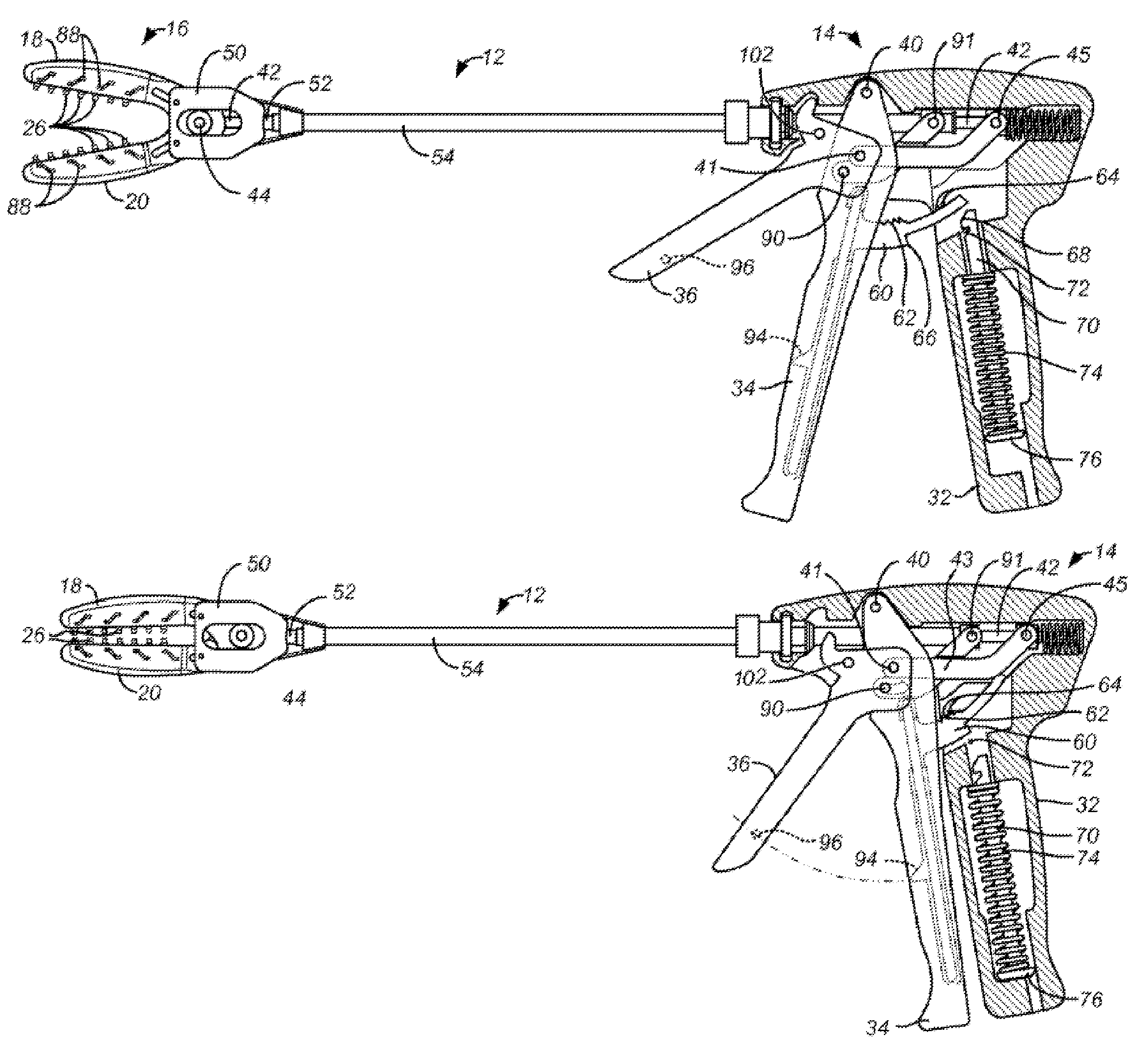
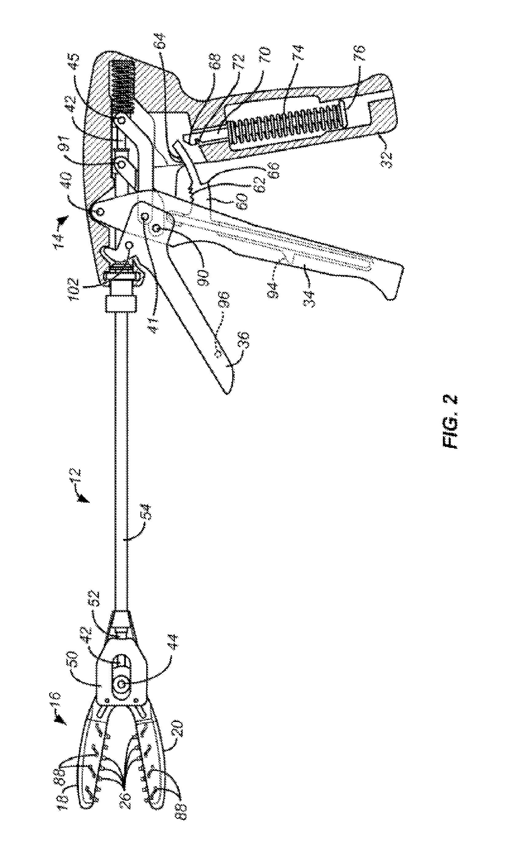
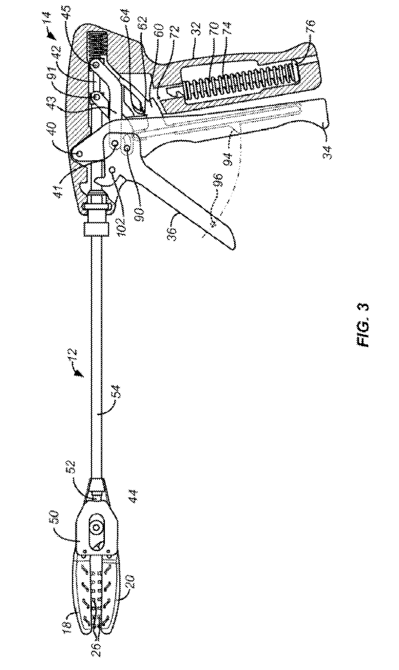
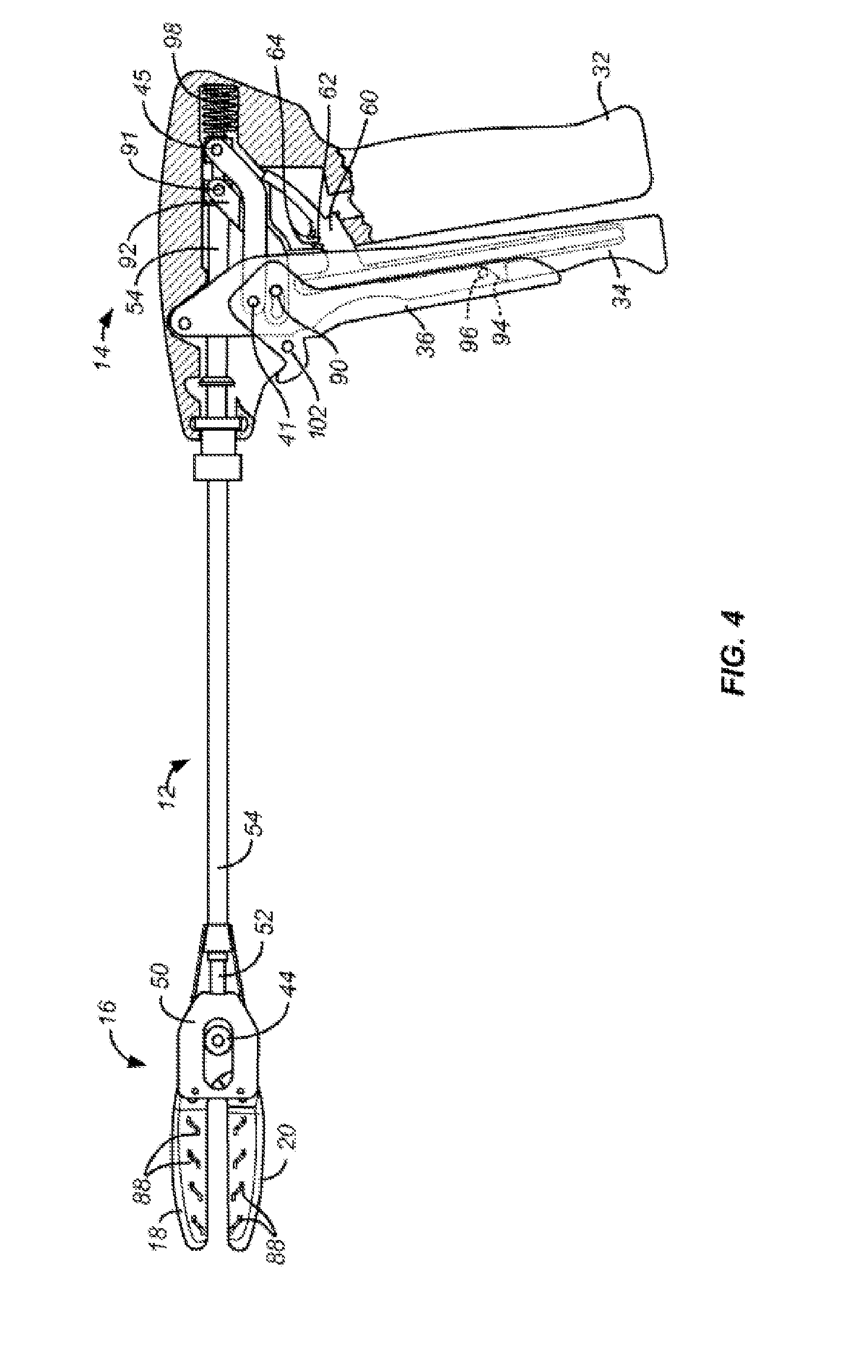
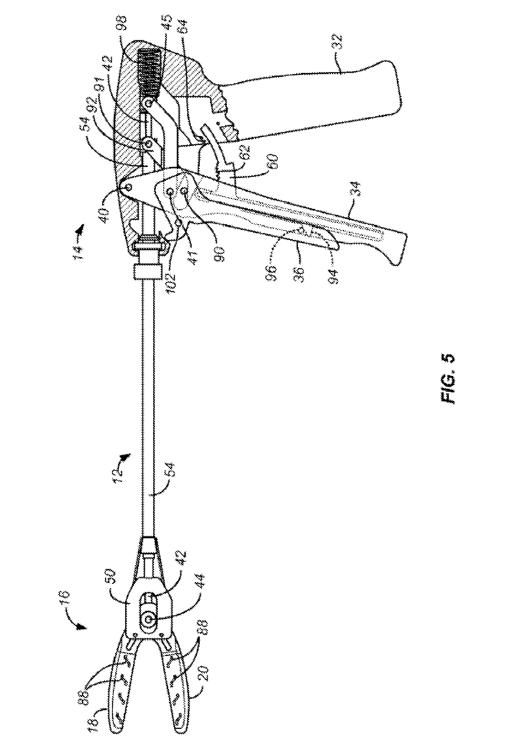
1. A surgical applicator for a fastener, comprising: a handle; a first trigger coupled movably with respect to the handle; a second trigger coupled movably with respect to the first trigger, but operatively arranged to move in tandem with the first trigger during movement of the first trigger; a first interlock coupled to the second trigger and operatively arranged to selectively prevent movement of the second trigger relative to the first trigger depending on a position of the first trigger with respect to the handle; and a second interlock coupled to the first trigger and operatively arranged to selectively prevent movement of the first trigger relative to the handle depending on a position of the second trigger.
2. The applicator of claim 1, wherein the first interlock permits movement of the second trigger relative to the first trigger when the first trigger is moved from a first position to a second position, and restricts movement of the second trigger relative to the first trigger when the first trigger is not in the second position.
3. The applicator of claim 1 further comprising a jaw assembly that is selectively opened and closed via movement of the first trigger.
4. The applicator of claim 3, wherein movement of the second trigger selectively retracts one or more fastener supporting structures of the jaw assembly with respect to at least one jaw of the jaw assembly.
5. The applicator of claim 1, wherein the first interlock includes a cam follower engaged with a cam channel.
6. The applicator of claim 5, wherein the handle includes the cam channel and the second trigger includes the cam follower.
7. The applicator of claim 5, wherein the cam channel has a first leg that permits tandem movement of the second trigger with the first trigger during closing of the first trigger and a shoulder that prevents movement of the second trigger relative to the first trigger until the first trigger is closed.
8. The applicator of claim 7, wherein the cam channel has a second leg that permits tandem movement of the second trigger with the first trigger during re-opening of the first trigger after the second trigger has been closed relative to the first trigger.
9. The applicator of claim 5, wherein the cam channel includes at least one leg formed concentrically with respect to a first pivot about which the first trigger is rotatably coupled to the handle and a transverse portion formed concentrically with respect to a second pivot about which the second trigger is rotatably coupled to the first trigger.
10. The applicator of claim 9, wherein the at least one leg includes two legs, and the transverse portion is connected between the two legs.
11. A surgical applicator for a fastener, comprising: a handle; a first trigger coupled movably with respect to the handle; a second trigger coupled movably with respect to the first trigger, but operatively arranged to move in tandem with the first trigger during movement of the first trigger; and an interlock coupled to the second trigger and operatively arranged to selectively prevent movement of the second trigger relative to the first trigger depending on a position of the first trigger with respect to the handle; wherein the interlock includes a cam follower engaged with a cam channel, and wherein the handle includes the cam channel and the second trigger includes the cam follower.
12. The applicator of claim 11, wherein the interlock permits movement of the second trigger relative to the first trigger when the first trigger is moved from a first position to a second position, and restricts movement of the second trigger relative to the first trigger when the first trigger is not in the second position.
13. The applicator of claim 11 further comprising a jaw assembly that is selectively opened and closed via movement of the first trigger.
14. The applicator of claim 13, wherein movement of the second trigger selectively retracts one or more fastener supporting structures of the jaw assembly with respect to at least one jaw of the jaw assembly.
15. A surgical applicator for a fastener, comprising: a handle; a first trigger coupled movably with respect to the handle; a second trigger coupled movably with respect to the first trigger, but operatively arranged to move in tandem with the first trigger during movement of the first trigger; and an interlock coupled to the second trigger and operatively arranged to selectively prevent movement of the second trigger relative to the first trigger depending on a position of the first trigger with respect to the handle; wherein the interlock includes a cam follower engaged with a cam channel, and wherein the cam channel has a first leg that permits tandem movement of the second trigger with the first trigger during closing of the first trigger and a shoulder that prevents movement of the second trigger relative to the first trigger until the first trigger is closed.
16. The applicator of claim 15, wherein the cam channel has a second leg that permits tandem movement of the second trigger with the first trigger during re-opening of the first trigger after the second trigger has been closed relative to the first trigger.
17. The applicator of claim 15, wherein the interlock permits movement of the second trigger relative to the first trigger when the first trigger is moved from a first position to a second position, and restricts movement of the second trigger relative to the first trigger when the first trigger is not in the second position.
18. The applicator of claim 15 further comprising a jaw assembly that is selectively opened and closed via movement of the first trigger.
19. The applicator of claim 18, wherein movement of the second trigger selectively retracts one or more fastener supporting structures of the jaw assembly with respect to at least one jaw of the jaw assembly.
20. A surgical applicator for a fastener, comprising: a handle; a first trigger coupled movably with respect to the handle; a second trigger coupled movably with respect to the first trigger, but operatively arranged to move in tandem with the first trigger during movement of the first trigger; and an interlock coupled to the second trigger and operatively arranged to selectively prevent movement of the second trigger relative to the first trigger depending on a position of the first trigger with respect to the handle; wherein the interlock includes a cam follower engaged with a cam channel, and wherein the cam channel includes at least one leg formed concentrically with respect to a first pivot about which the first trigger is rotatably coupled to the handle and a transverse portion formed concentrically with respect to a second pivot about which the second trigger is rotatably coupled to the first trigger.
21. The applicator of claim 20, wherein the at least one leg includes two legs, and the transverse portion is connected between the two legs.
22. The applicator of claim 20, wherein the interlock permits movement of the second trigger relative to the first trigger when the first trigger is moved from a first position to a second position, and restricts movement of the second trigger relative to the first trigger when the first trigger is not in the second position.
23. The applicator of claim 20 further comprising a jaw assembly that is selectively opened and closed via movement of the first trigger.
24. The applicator of claim 23, wherein movement of the second trigger selectively retracts one or more fastener supporting structures of the jaw assembly with respect to at least one jaw of the jaw assembly.
Description
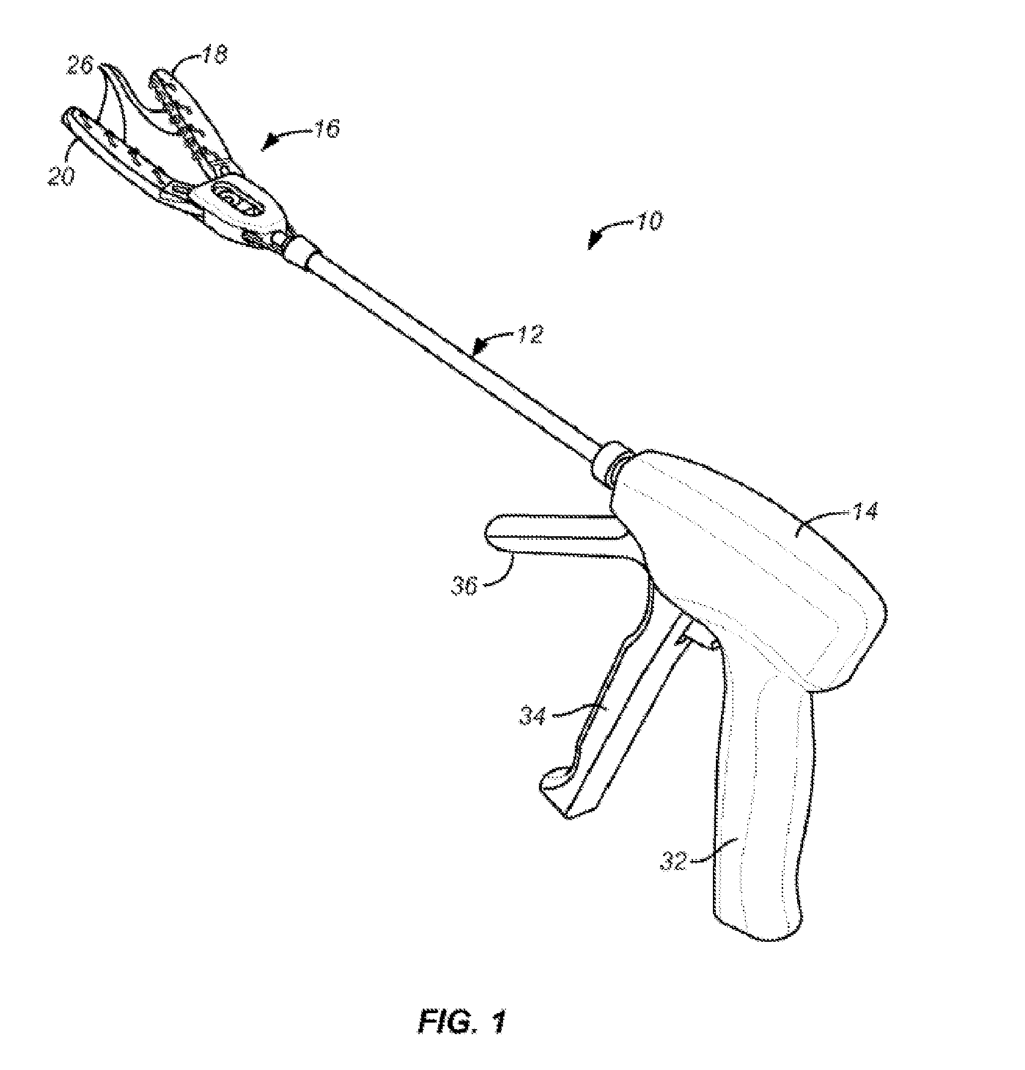
FIELD OF THE DISCLOSURE
The present disclosure pertains broadly to the field of fasteners and/or applicators. More specifically, the disclosure relates to surgical applicators of implants and/or fasteners, including but not limited to sterilized fasteners such as staples.
BACKGROUND
Atrial fibrillation is a relatively common condition characterized by a very rapid heartbeat of the left and right atrium. While atrial fibrillation is not normally fatal itself, it has been associated with an increased risk of stroke. It is believed that the rapid heartbeat causes blood to pool in the left atrial appendage which causes emboli that are released into the left atrium from where they can enter the cerebral vasculature, thus causing a stroke. In addition to stroke, the emboli can enter coronary circulation, potentially causing myocardial infarction, or can enter peripheral circulation, potentially causing peripheral vascular disease.
The risk of stroke in patients suffering from atrial fibrillation can be reduced in a variety of ways. For example, blood thinning drugs can be used to reduce the risk of clot formation. The use of blood thinners, however, is contraindicated in patients at risk of bleeding disorders. More aggressive treatment protocols have been proposed which involve closing the left atrial appendage. Closure and excision may be performed in open surgical procedures, typically requiring the patient to be placed on by-pass and the chest to be opened through the sternum. Alternatively, thoracoscopic and other less invasive procedures have been proposed. U.S. Pat. No. 5,306,234 teaches the performance of beating heart procedures using otherwise conventional surgical techniques. The use of conventional techniques through small chest penetrations while the heart is beating can be difficult to perform. U.S. Pat. No. 5,865,791 describes an intravascular approach where tools are introduced through the vasculature and passed into the left atrium. The tools are used to ablate or fuse the left atrial appendage from the inside using energy, adhesives, or the like. The '791 patent also describes a thoracoscopic procedure where a tether is placed over the neck of the atrial appendage and tied off to achieve isolation. The '791 patent still further suggests other closure elements including sutures, staples, shape-memory wires, biocompatible adhesives, and the like. U.S. Pat. No. 6,488,689 describes a transpericardial procedure where the distal tip of the left atrial appendage is grasped and pulled backwardly through a capture loop which encircles the base of the left atrial appendage.
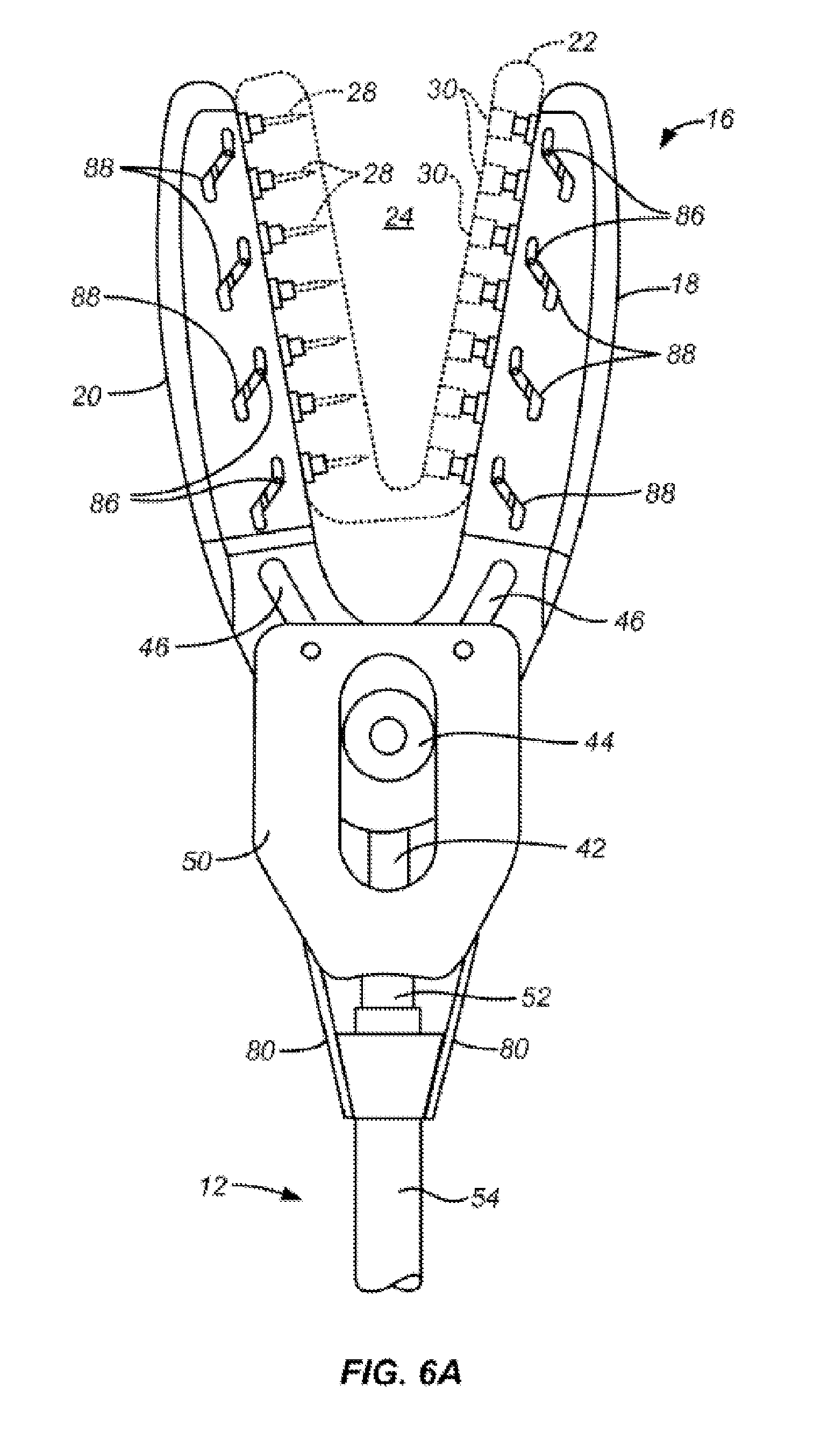
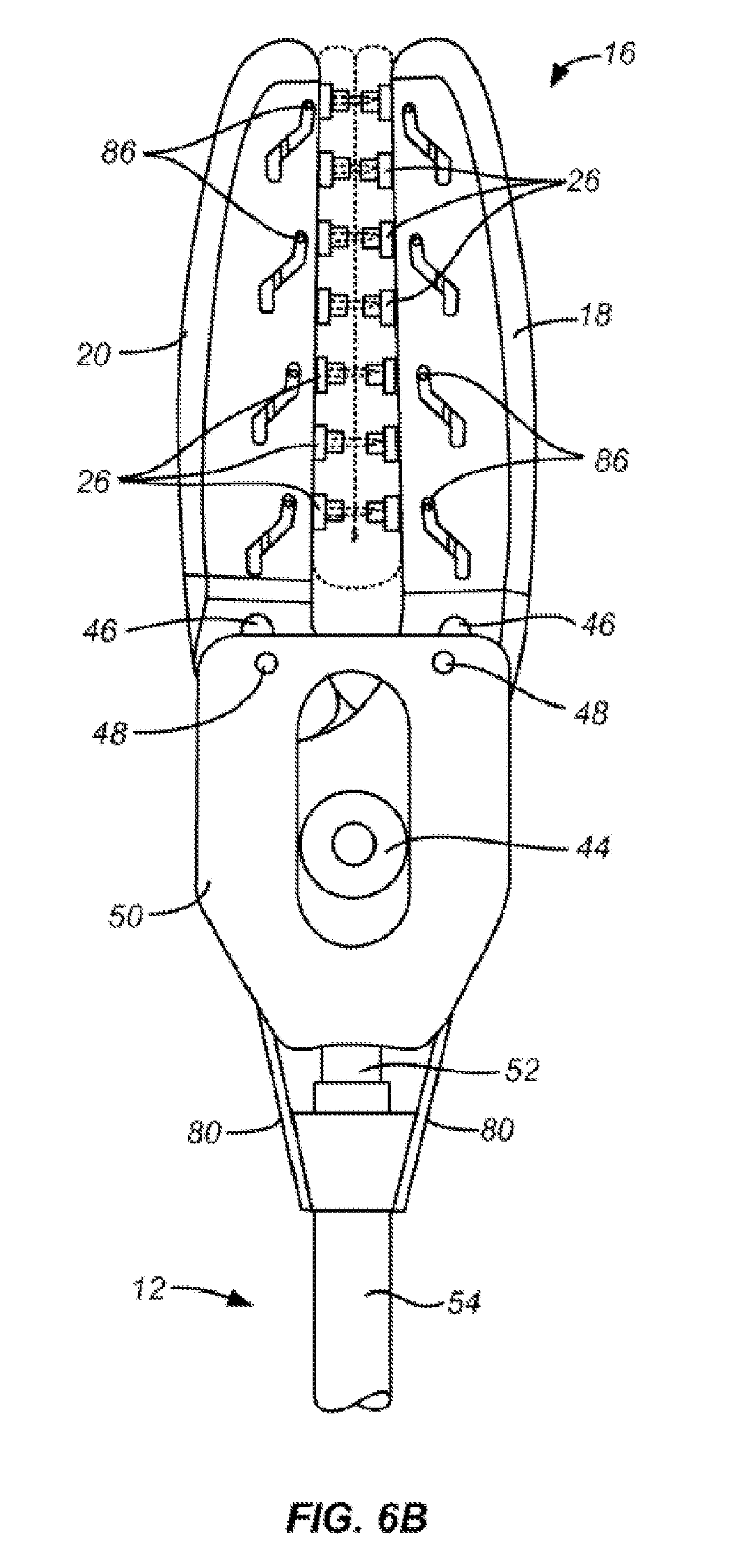
A compliant closure structure for the sealing bodily structures such as the left atrial appendage is described in co-pending, commonly owned U.S. Patent Publication 2007/0260278 (application Ser. No. 11/744,135), the full disclosure of which is incorporated herein by reference in its entirety. The compliant structure described in the '278 publication comprises an elastomeric body having a pair of opposed legs which may be arranged in an oval or a U-shaped configuration to define an opening therebetween. By placing the opening between the legs over the left atrial appendage and aligning it with the base of the appendage, the structure may be closed to provide the desired sealing. To hold the structure closed, a number of discrete, axially spaced-apart tissue penetrating fasteners are arranged along the lengths of each of the legs. By compressing the legs together to press-fit the closure devices, the compliant structure may be closed to provide a compliant seal which effectively isolates the left atrial appendage.
The '278 publication describes a particular delivery tool for the compliant closure structure. The delivery tool includes jaws which can be inserted into the legs of the closure structure and actuated to close the jaws in the legs over the left atrial appendage. The jaws further include comb studs which engage and press fit the closure devices in order to hold the compliant structure in its closed, sealing configuration. The studs are intended to be retracted to allow the delivery tool to be removed.
Although functional, the delivery tool of the '278 publication has certain shortcomings. For example, the actuation of the jaws and retraction of the comb studs can be performed out of order, increasing the risk that the delivery of the compliant structure will fail. Moreover, positioning and orientation of the delivery tool can be difficult, particularly when the tool is introduced through an intercostal penetration to access the left atrium. Additionally, the jaws in the device of the '278 publication are attached in the axial plane of the device shaft. Such a straight line of attachment can make it more difficult to align the jaws with the base of the appendage and across the os (i.e., ostium) of the atrium leading into the appendage. If the closure device is not aligned across the base to completely close the os, gaps or openings (referred to as "cul-de-sacs") can remain at the site of closure, increasing the risk of thrombus formation in the atrium. The importance of forming a complete seal of the os which is free from such cul-de-sacs is discussed in Salzberg et al. (2008) Eur. J. Cardiothoracic Surg. 34:766-770.
For these reasons, it would be desirable to provide improved delivery tools for use with the tissue closure devices described in U.S. Patent Publication 2007/0260278. It would be further desirable if the delivery tools and methods of their use were compatible with the delivery of other tissue closure devices and for procedures in addition to closure of the left atrial appendage.
SUMMARY
A surgical applicator for a fastener according to an example embodiment comprises a handle, a first trigger coupled movably with respect to the handle, and a second trigger coupled movably with respect to the first trigger, but operatively arranged to move in tandem with the first trigger during movement of the first trigger. An interlock is coupled to the second trigger and operatively arranged to selectively prevent movement of the second trigger relative to the first trigger depending on a position of the first trigger with respect to the handle.
According to an example embodiment, the interlock permits movement of the second trigger relative to the first trigger when the first trigger is moved from a first position to a second position, and restricts movement of the second trigger relative to the first trigger when the first trigger is not in the second position.
According to an example embodiment, a second interlock is coupled to the first trigger and operatively arranged to selectively prevent movement of the first trigger relative to the handle depending on a position of second trigger.
According to an example embodiment, a jaw assembly is selectively opened and closed via movement of the first trigger.
According to an example embodiment, movement of the second trigger selectively retracts one or more fastener supporting structures of the jaw assembly with respect to at least one jaw of the jaw assembly.
According to an example embodiment, the interlock includes a cam follower engaged with a cam channel.
According to an example embodiment, the handle includes the cam channel and the second trigger includes the cam follower.
According to an example embodiment, the cam channel has a first leg that permits tandem movement of the second trigger with the first trigger during closing of the first trigger and a shoulder that prevents movement of the second trigger relative to the first trigger until the first trigger is closed.
According to an example embodiment, the cam channel has a second leg that permits tandem movement of the second trigger with the first trigger during re-opening of the first trigger after the second trigger has been closed relative to the first trigger.
According to an example embodiment, the cam channel includes at least one leg formed concentrically with respect to a first pivot about which the first trigger is rotatably coupled to the handle and a transverse portion formed concentrically with respect to a second pivot about which the second trigger is rotatably coupled to the first trigger.
According to an example embodiment, the at least one leg includes two legs, and the transverse portion is connected between the two legs.
A fastener applicator according to an example embodiment comprises a handle, a first trigger coupled rotatably with respect to the handle, and a second trigger coupled rotatably with respect to the handle. An interlock is disposed with the second trigger and comprises a cam follower engaged in a cam channel that selectively prevents rotation of the second trigger relative to the first trigger depending on a location of the cam follower within the cam channel. The location of the cam follower in the cam channel is set by a position of the first trigger.
According to an example embodiment, the handle includes the cam channel and the second trigger includes the cam follower.
According to an example embodiment, the cam channel has a first leg that permits tandem movement of the second trigger with the first trigger during closing of the first trigger and a shoulder that prevents movement of the second trigger relative to the first trigger until the first trigger is closed.
According to an example embodiment, the cam channel has a second leg that permits tandem movement of the second trigger with the first trigger during re-opening of the first trigger after the second trigger has been closed relative to the first trigger.
A fastener applicator according to an example embodiment comprises a handle, a shaft extending distally from the handle and a jaw assembly at a distal end of the shaft having one or more fastener supporting structures. A first trigger is coupled movably with respect to the handle and to the jaw assembly such that movement of the first trigger relative to the handle selectively closes the jaw assembly. A second trigger is coupled movably with respect to the first trigger, the second trigger coupled to the jaw assembly such that movement of the second trigger relative to the first trigger selectively retracts the one or more fastener supporting structures; and an interlock coupled to the second trigger and operatively arranged to selectively prevent movement of the second trigger relative to the first trigger depending on a position of the first trigger.
According to an example embodiment, the interlock permits movement of the second trigger relative to the first trigger when the first trigger is closed and prevents movement of the second trigger relative to the first trigger when the first trigger is open.
According to an example embodiment, a second interlock is coupled to the first trigger and operatively arranged to selectively prevent movement of the first trigger relative to the handle depending on a position of second trigger.
According to an example embodiment, the interlock includes a cam follower engaged with a cam channel.
According to an example embodiment, the handle includes the cam channel and the second trigger includes the cam follower.
According to an example embodiment, the second trigger is movable in tandem with the first trigger during movement of the first trigger.
A fastener applicator according to an example embodiment comprises a handle, a first trigger movable with respect to the handle between a first position and a second position, and a second trigger movable with respect to the first trigger between an initial position and an actuated position. A first interlock is coupled to the second trigger and operatively arranged to selectively prevent movement of the second trigger relative to the first trigger until the first trigger is moved into the second position. A second interlock is coupled to the first trigger and operatively arranged to selectively prevent movement of the first trigger relative to the handle until the second trigger is moved into the actuated position.
According to an example embodiment, a pair of jaws is included, with the first trigger coupled to the pair of jaws for setting the pair of jaws in an open configuration when the first trigger is in the first position and in a closed configuration when the first trigger is in the second position.
According to an example embodiment, one or more fastener supporting structures are disposed with the pair of jaws. The second trigger is coupled to the one or more fastener supporting structures for setting the one or more fastener supporting structures in a deployed configuration when the second trigger is in the initial position and in a retracted configuration when the second trigger is in the actuated position.
A method of operating a fastener applicator according to an example embodiment comprises: (i) repositioning a first trigger of the fastener applicator with respect to a handle from a first position to a second position, (ii) moving a second trigger in tandem with the first trigger, (iii) preventing repositioning of a second trigger between an initial position and an actuated position relative to the first trigger with an interlock coupled to the second trigger until the first trigger is moved to the second position, and (iv) repositioning the second trigger to the actuated position relative to the first trigger after the first trigger is moved to the second position.
A method of operating a fastener applicator according to an example embodiment comprises: (i) moving a first trigger of the fastener applicator with respect to a handle from a first position to a second position, (ii) preventing movement of a second trigger between an initial position and an actuated position relative to the first trigger with an interlock coupled to the second trigger until the first trigger is moved to the second position, (iii) rearranging a cam follower and a cam channel of the interlock with respect to each other due to the moving of the first trigger to the second position, and (iv) moving the second trigger to the actuated position relative to the first trigger after the first trigger is moved to the second position.
A method of operating a fastener applicator according to an example embodiment comprises: (i) moving a first trigger of the fastener applicator with respect to a handle from a first position to a second position, (ii) preventing movement of a second trigger between an initial position and an actuated position relative to the first trigger with a first interlock coupled to the second trigger until the first trigger is moved to the second position, (iii) moving the second trigger to the actuated position relative to the first trigger after the first trigger is moved to the second position, (iv) preventing movement of the first trigger relative to the handle back to the first position with a second interlock coupled to the first trigger until the second trigger is moved to the actuated position, and (v) moving the first trigger back to the first position relative to the handle after the second trigger is moved to the actuated position.
A method of operating a fastener applicator according to an example embodiment comprises: (i) repositioning a first trigger of the fastener applicator with respect to a handle from a first position to a second position, (ii) closing a jaw assembly coupled to the handle of the fastener applicator due to movement of the first trigger to the second position, (iii) preventing repositioning of a second trigger between an initial position and an actuated position relative to the first trigger with an interlock coupled to the second trigger until the first trigger is moved to the second position, (iv) repositioning the second trigger to the actuated position relative to the first trigger after the first trigger is moved to the second position, and (v) retracting one or more fastener supporting structures comprising at least one protrusion movably extendable and retractable with respect to at least one jaw of the jaw assembly of the fastener applicator due to repositioning of the second trigger to the actuated position.
According to an example embodiment, the fastener applicator comprises a second interlock coupled to the first trigger and the method further comprises preventing movement of the first trigger from the second position to the first position with the second interlock until the second trigger is moved to the actuated position relative to the first trigger, and repositioning the first trigger from the second position back to the first position after the second trigger is moved to the actuated position relative to the first trigger.
According to an example embodiment, the interlock includes a cam follower engaged with a cam channel.
According to an example embodiment, rotating the first trigger from the first position to the second position includes traversing the cam follower along a first leg of the channel.
According to an example embodiment, the first leg is formed concentrically with respect to a pivot about which the first trigger rotates.
According to an example embodiment, rotating the second trigger to the actuated position relative to the first trigger includes traversing the cam follower along a portion of the channel transverse to the first leg.
According to an example embodiment, the handle includes the cam channel and the second trigger includes the cam follower.
According to an example embodiment, rotating the first trigger from the first position to the second position including moving the second trigger in tandem with the first trigger.
BRIEF DESCRIPTION OF THE DRAWINGS
The following descriptions should not be considered limiting in any way. With reference to the accompanying drawings, like elements are numbered alike:
FIG. 1 is a perspective view of a closure device applicator constructed in accordance with to an example embodiment of the present disclosure;
FIG. 2 is a partial cross-sectional elevation view of the closure device applicator of FIG. 1, shown with the jaws open and rotated 90.degree. relative to the position shown in FIG. 1;
FIG. 3 is a partial, cross-sectional elevation view of the device applicator similar to FIG. 2, shown with the first trigger closed relative to the handle in order to close the jaws, and the second trigger open (or spaced apart) with respect to the first trigger;
FIG. 4 is a partial, cross-sectional elevation view of the closure device applicator similar to that shown in FIGS. 2 and 3 with the second trigger closed relative to the first trigger demonstrating a retraction of the closure device-engaging studs;
FIG. 5 is a partial, cross-sectional elevation view of the closure device applicator of FIGS. 2-4, shown with the first trigger re-opened with respect to the handle in order to open the jaws while the closure device-engaging studs remain retracted;
FIG. 6A-6D illustrate the movement of the jaw and stud engagement with the closure devices of a tissue closure device according to an example embodiment of the present disclosure;
FIG. 7 illustrates an exemplary mechanism by which the closure device-engaging studs are retracted within the jaws according to an example embodiment of the present disclosure;
FIG. 8 illustrates an interlock formed between a cam channel, slot, or groove in a handle of the applicator of FIG. 1, shown in cross-section, and a cam follower projecting from a second trigger of the applicator of FIG. 1, shown in a perspective and exploded view orientation according to an embodiment of the present disclosure;
FIGS. 9A-9E illustrate various positions of the cam follower of FIG. 8 along the cam channel of the interlock as first and second triggers of the applicator are moved through the configurations depicted in FIGS. 2-5;
FIG. 10 illustrates operation of the interlock of FIG. 8 with respect to the first and second triggers of the applicator of FIG. 1; and
FIG. 11 illustrates use of the applicator according to an example embodiment of the present disclosure, wherein the applicator is used for closing a closure device over a left atrial appendage.
DETAILED DESCRIPTION
A detailed description of one or more embodiments of the disclosed apparatus and method are presented herein by way of exemplification and not limitation with reference to the Figures.
Embodiments of the present disclosure provide alternative and improved apparatuses, systems, and methods for deploying one or more closure devices or fasteners to tissue. An exemplary tissue structure of a patient at risk of stroke or other adverse events resulting from emboli released into circulation from the left atrial appendage, may include the left atrial appendage. Patients benefiting from the exemplary procedures disclosed herein will at least partially include those suffering from atrial fibrillation which can cause clot and thrombus formation in the left atrial appendage, thus increasing the chance of emboli release.
Exemplary embodiments of the present disclosure provide a mechanical closure device applicator for introducing the fastener over the tissue structure, which fastener is left in place in order to close and/or seal the tissue structure. A portion of the tissue structure extending beyond the fastener may then be cut, excised, or otherwise removed, although this may be left to the physician's preference. In one embodiment, the tissue fastener comprises a compression body having at least two opposed, compliant tissue-engaging surfaces which are placed over opposite sides of the tissue structure. In this embodiment, the tissue-engaging surfaces are held together by a plurality of axially spaced-apart tissue-penetrating fasteners, which extend from one of the surfaces, through the intermediate tissue, and into the other surface to both hold the compression body in place and to apply a desired level of compression force, which is determined by both the softness of the compression body and the distance between the surfaces when they are fully attached. A well may be provided in the compression body around the tissue-penetrating barb of the fastener such that a gasket seal is formed by the compression body around the puncture site in the tissue. A stabilizing lip may be provided in one leg of the compression body to prevent a rolling motion of one leg with respect to another leg of the compression body in order to keep the two opposing soft members linearly aligned. More detailed descriptions of fasteners suitable for use with embodiments of the present disclosure are found in patent publication U.S. 2007/0260278, the full disclosure of which has been previously incorporated herein by reference.
Referring now to FIG. 1, a fastener applicator 10 constructed in accordance with various embodiments of the present disclosure comprises a shaft 12 having a handle assembly 14 at its proximal end, and a jaw assembly 16 at a distal end, where individual jaws 18 and 20 are adapted to carry a fastener 22, as best illustrated in FIGS. 6A-6D. The fastener 22 is shown in an example embodiment to have a IJ-shaped configuration which defines a V-shaped region 24 for receiving the left atrial appendage or other tissue structure when the jaws are open as shown in FIGS. 1, 2, and 6A. A plurality of studs 26 are formed along the inner surfaces of each jaw 20 and 18 to engage tissue-penetrating fasteners which comprise penetrating components 28 and receptacle components 30, as best shown in FIG. 6A. The handle assembly 14 will include a handle 32, a first trigger 34, and a second trigger 36.
Referring now to FIGS. 2 and 6A, the fastener applicator 10 is shown in its shelf or delivery configuration with the fastener 22 received over the jaw assembly 16 and the V-shaped opening 24 in the device ready to be placed over a tissue structure such as the left atrial appendage (see FIG. 10). The triggers 34 and 36 are each respectively movable between an initial or first position and an actuated or second position. As will be discussed in more detail below, the first trigger 34 is movable between its respective positions relative to the handle 32, while the second trigger 36 is movable between its respective positions relative to the first trigger 34. In one embodiment, in their respective first positions, the first trigger 34 and the second trigger 36 are initially in a fully open position, that is, pivoted fully away from the handle 32. For this reason, it is to be understood that any mention of "opening" the first trigger 34 refers more generally to moving the first trigger 34 toward its first or initial position, while any mention of "closing" the first trigger 34 or the second trigger 36 refers more generally to moving the first trigger 34 or the second trigger 36 towards its respective second or actuated position.
After the fastener 22 is advanced over the left atrial appendage or other target tissue structure, the jaws 18 and 20 are closed by manually pulling the first trigger 34 toward the handle 32, as shown in FIGS. 3 and 6B. The first trigger 34 is mounted on a pin or pivot 40, which is shown to be fixedly secured to the handle assembly 14, thereby rotatably coupling the first trigger 34 to the handle 32. Closing the first trigger 34 with respect to the handle 32, that is, pivoting about the pivot 40 from the first position of the first trigger 34 to the second position, proximally retracts the rod 42 which is linked to the first trigger 34 by a pin or pivot 41 and a lever 43. The rod 42 is attached to a pin 44 (FIG. 6B) which is pivotally attached to the proximal ends of the jaws 18 and 20 and proximally retracts the jaws so that they are closed by the movement of slots 46 over pins 48 in an end frame 50 attached to a stationary sleeve 52. When the jaws 18 and 20 are closed, the studs 26 engage the tissue penetrating components 28 and the tissue penetrating receptacles 30 so that they engage and lock with each other, thus closing the two legs of the fastener 22, as shown in FIG. 6B.
The second trigger 36 may be mounted on the pin 41 so that the second trigger 36 moves, actuates, or closes with respect to the handle 32 in tandem with the first trigger 34. In this way, the second trigger 36 is rotatably coupled to the handle 32, although indirectly via the pin 41 and the first trigger 34. By "in tandem" it is meant that movement of the first trigger 34 translates at least partially into corresponding movement of all or portions of the second trigger 36. In the illustrated embodiment, movement of the first trigger 34 causes a substantially equivalent amount of rotational movement of the second trigger 36, although there could be gears, linkages, springs, or the like to cause a lesser or greater degree of movement of the second trigger 36 to result from corresponding movement of the first trigger 34.
The applicator 10 may optionally include an interlock 60 in some embodiments. According to the illustrated embodiment, as the first trigger 34 and the second trigger 36 are moved in tandem, a ratcheting tooth surface 62 of the interlock 60 is closed against pins 64, as shown in FIG. 3, so that the first trigger 34 cannot be re-opened once the jaw assembly 16 has been closed, either completely or to a certain degree of closure or spacing between the jaws. This is advantageous as described above, since the jaws should not be completely opened prior to retracting the studs 26 by closing the second trigger 36, as will be described below. The ratcheting tooth surface 62 can include any number of ratchets or notches such that the first trigger 34 can be progressively closed (i.e., brought into approximation of the handle 32) by more fully driving the ratcheting tooth surface 62 along the pins 64 in the direction of closure for the first trigger 34 (e.g., from the configuration of FIG. 2 to the configuration of FIG. 3).
Additionally, as the first trigger 34 is moved to its actuated, closed, or second position (i.e., moved or actuated to the configuration of FIG. 3) in order to close the jaws 18 and 20 of the jaw assembly 16, a corner 66 (see FIG. 2) of the interlock 60 will engage an inclined surface 68 on a clicker pin 70 to disengage the clicker pin 70 from a holding pin 72, thus allowing a spring 74 to push the pin 70 downward so that a bottom surface 76 thereof strikes the bottom of the handle 32, thus causing a loud click to audibly alert the physician that the jaws have been closed and the interlock 60 has been engaged. This audible confirmation indicates to the physician or other medical personnel that the fastener 22 has been closed and that the studs 26 can be retracted.
The studs 26 are initially in an extended configuration, as shown in FIGS. 2-3 and 6A-6B, and then retracted by closing second trigger 36 against the first trigger 34, as shown in FIGS. 4 and 6C. Closure of the second trigger 36 relative to the first trigger 34 draws the outer sleeve 54 proximally over the stationary sleeve 52 which draws pull wires 80 proximally to pull stud combs 84 or other fastener supporting structures, proximally, as shown in FIG. 7. The stud combs 84 are mounted on pins 86 which travel in slots 88 formed in each of the jaws 18 and 20. The second trigger 36 is pivotally mounted on, or rotatably coupled to, the first trigger 34 by the pin 41 and is coupled to the stationary sleeve by pins 90 and 91 and a lever 92. It is to be appreciated that the studs 26 can take other shapes or arrangements and/or that other fastener supporting structures (i.e., structures capable of supporting the fasteners 22 during closing and engaging thereof) can be included in lieu of the studs 26 that are either disengaged from or engaged to the fastener 22 upon intentional closure or movement of the second trigger 36. For example, in lieu of a plurality of individual studs 26, a supporting structure in the form of a single unitary rail supporting all of the components 28 can be included in one embodiment.
Movement of the second trigger 36 relative to the first trigger 34, e.g., closure of the second trigger 36, disengages the interlock 60 by engaging a ramped surface 94 attached to the interlock 60 against a fixed pin 96 in the second trigger 36. In this way, the interlock 60 selectively permits or prevents movement, e.g., opening, of the first trigger 34 depending on a position of the second trigger 36. In other words, movement of the second trigger 36 to its corresponding second position, relative to the first trigger 34, releases the interlock 60. The pin 96 follows the path shown in broken line in FIG. 3 to engage the surface 94. The ramped surface 94 is caused to move downwardly, pulling the ratchet teeth 62 away from the fixed pins 64, as shown in FIGS. 4 and 5. The triggers 34 and 36 are now ready to be opened in order to open the jaws, as will now be described.
Referring now to FIGS. 5 and 7C, the jaws 18 and 20 may be opened by releasing manual compression on the first and second triggers 34 and 36, allowing spring 98 which was compressed during closure of the first trigger 34 to push rod 42 (attached to pivot 44) distally forward, opening the jaws and leaving the fastener 22 in place.
FIG. 8 shows a cross-section of the handle 32 as well as the second trigger 36 exploded therefrom. An interlock 100 is included between the handle 32 and the second trigger 36 to selectively permit and prevent rotational movement of the second trigger 36 with respect to the first trigger 34. The first trigger 34 does not form a part of the interlock 100 in the illustrated embodiment, and therefore is not illustrated in FIG. 8. However, it is to be understood that the first trigger 34 in the embodiment of FIG. 8 would be nevertheless be secured to the second trigger 36 at the pivot 41 as described herein with respect to the other Figures. Additionally, the shaft 12 and the jaw assembly 16 are not illustrated in some Figures, including FIG. 8, but can be included as described herein with respect to the other Figures.
More specifically, the interlock 100 includes a cam follower 102 and a channel 104. In the illustrated embodiment, the cam follower 102 is formed as a protrusion or projection extending from or otherwise coupled to the second trigger 36, and is preferably round in cross section but alternatively may be of other shapes. The cam follower 102 can be integrally formed with the second trigger 36 or affixed thereto as a separate component. The channel 104 may be formed as a groove, depression, notch, slot, or the like in the handle 32. The follower 102 is configured to engage with and/or travel along the channel 104 (and thus will be restricted to movement within the channel 104) when the second trigger 36 is assembled with the handle 32. It is noted that the applicator 10 can include other exemplary embodiments of a single follower 102 and a single channel 104 if desired, but for symmetry, balance, etc., the second trigger 36 may include two cam followers 102 (e.g., another follower 102 hidden from view in FIG. 8 on the opposite lateral side of the second trigger 36 and mirroring the illustrated one of the followers 102 about a plane bisecting the second trigger 36), and the handle 32 may correspondingly include two cam grooves 104 (e.g., another channel 104 located in the half of the handle 32 not shown in FIG. 8, which mirrors the illustrated channel 104 about the plane used to form the cross-sectional view of the handle 32 in FIG. 8).
The mechanical coupling of the follower 102 to the second trigger 36 prevents rotation of the second trigger 36 relative to the first trigger 34 when the follower 102 abuts against the walls or shoulders defining the channel 104. For example, FIGS. 9A-9E show various positions of the follower 102 (without the second trigger 36 for clarity) corresponding to the various combinations of positions of the first and second triggers 34 and 36 of the applicator 10. That is, for example, the position of the follower 102 in FIG. 9A corresponds to an initial, shelf, or delivery configuration of the applicator 10 shown in FIG. 2, i.e., before the triggers 34 or 36 have been actuated.
In the position of FIG. 9A, rotation of the second trigger 36 is prevented by interference of the follower 102 with a shoulder 106 of the channel 104. That is, movement of the second trigger 36 relative to the first trigger 34 occurs about the pin 41, which rotationally couples the second trigger 36 to the first trigger 34. Thus, rotation of the second trigger 36 about the pin 41 (if unblocked) would result in the cam follower 102 following an arc defined by a circular path concentric with the pin 41, e.g., illustrated as a circle 107 in FIG. 10. From FIG. 10, it is clear that rotational movement of the cam follower 102 along an arc defined by the circle 107 is not possible due to interference between the cam follower 102 and the shoulder 106. Accordingly, rotation of the second trigger 36 about the pin 41 relative to the first trigger 34 is prevented by the interference between the cam follower 102 and the shoulder 106.
The channel 104 is shaped with a leg 108, which permits the second trigger 36 to travel in tandem with the first trigger 34 as the first trigger 34 is moved toward its second position, i.e., rotated about the pivot 40 toward the configuration of the applicator 10 shown in FIG. 3. That is, again referring to FIG. 10, tandem movement of second trigger 36 due to movement of the first trigger 34 would result in the cam follower 102 traveling along an arc defined by a circular path concentric with the pivot 40, illustrated in FIG. 10 by a circle 109. The first leg 108 is arranged to lie substantially along such an arc formed by the circle 109, thereby enabling the cam follower 102 to travel along the leg 108 during rotation of the first and second triggers 34 and 36 about the pin 40.
FIG. 9B illustrates the position of the follower 102 in the channel 104 when the first trigger 34 is rotated partially toward the configuration of FIG. 3, e.g., with ratcheting tooth surface 62 of the interlock 60 at most only partially driven along and engaged with the pins 64. At the position of FIG. 9B, the shoulder 106 continues to prevent rotation of the second trigger 36 by blocking movement of the follower 104 in the direction necessary to rotate the second trigger 36.
FIG. 9C illustrates the position of the follower 102 after the trigger first 34 has been moved to the configuration of FIG. 3 and the ratcheting tooth surface 62 of the interlock 60 is fully driven along and engaged with the pins 64. It can be appreciated in view of FIGS. 3 and 9C that rotation of the second trigger 36 becomes possible at this position because the shoulder 106 no longer abuts the follower 102. Alternatively stated, it is to be appreciated that tandem movement of the second trigger 36 with the first trigger 34 has shifted the position of the cam follower 102 and the pin 41 relative to the channel 104 (since the pin 41 and the cam follower 102 are directly coupled to the second trigger 36 in the illustrated embodiment). It is to be further understood that this shifting of the position of the pin 41 and the cam follower 102 has also moved the location of the circle 107 to align with a portion 110 of the channel 104 that is transverse to the leg 108 and arranged along an arc that is concentric with respect to the pin 41.
In view of the foregoing it can be seen that the position of the first trigger 34 selectively prevents or permits rotation of the second trigger 36. Again, movement of the first trigger 34 causes tandem movement of the second trigger 36, which results in the follower 102 first traversing along the leg 108 of the channel 104. However, movement of the second trigger 36 relative to the first trigger 34 is prevented due to interference between the cam follower 102 and the shoulder 106. Relative movement of the second trigger 36 with respect to the first trigger 34 is thus prevented until the cam follower 102 is moved to a position at which the cam follower 102 no longer abuts the shoulder 106. FIG. 9D shows the position of the follower 102 after movement of the second trigger 36 relative to the first trigger 34 is permitted and the second trigger 36 has also been actuated to its second position, thereby corresponding to the configuration of the applicator 10 shown in FIG. 4.
The channel 104 is shaped with another leg 112 that enables the follower 102 to continue to traverse the channel 104 such that the second trigger 36 can again move in tandem with the first trigger 34 as the first trigger 34 is moved to reopen the jaw assembly 16, i.e., as the first trigger 34 is moved back toward its first position. It is to be appreciated that the leg 112, similar to the leg 108, is formed along an arc that is concentric to the pivot 40. This accordingly enables the cam follower 102 to travel along the leg 112 as the second trigger 36 moved in tandem with the first trigger 34 as the first trigger 34 is rotated about the pivot 40. FIG. 9E accordingly shows the corresponding location of the follower 102 in the channel 104 when the first trigger 34 is returned to its first or initial position, which may correspond to the applicator 10 assuming the configuration of FIG. 5 in which the jaw assembly 16 is again opened.
It is to be appreciated that the channel 104 can take other shapes in other embodiments depending on the desired relative movement of the first and second triggers 34 and 36 relative to each other and to the handle 32. More specifically, the channel 104 will include a leg or portion for each optionally desired stage of movement of the first trigger 34 and of the second trigger 36, with the legs and/or portions of the channel 104 being concentric with respect to the pivot about which rotation is desired for each stage of movement. Thus, in order to sequentially permit (i) tandem movement of both of the first and second triggers 34 and 36 about a first pivot (e.g., the pivot 40), then (ii) movement of the second trigger 36 relative to the first trigger 34 about a second pivot (e.g., the pivot 41), and then (iii) tandem movement of the first and second triggers 34 and 36 again with respect to the first pivot, the channel 104 will include two legs (e.g., the legs 108 and 112) that are spaced apart but both concentric with respect to the first pivot (e.g., the pivot 40), which enables the movements of stages (i) and (iii), and a transverse portion (e.g., the portion 110) connecting between the two legs (e.g., the legs 108 and 112) that is formed concentrically with respect to the second pivot (e.g., the pivot 41) to enable the movement of stage (ii).
From the above description and the FIGS. 9A-9E, it is clear that the interlock 100 accordingly prevents rotation of the second trigger 36 until after the trigger first 34 is first rotated, preferably fully rotated (i.e., from a first position to a second position). Since full rotation of the first trigger 34 (e.g., as shown in FIG. 3) corresponds to the closing of the jaw assembly 16, the interlock 100 thus advantageously selectively prevents retraction of the studs 26 (due to rotation of the second trigger 36) until after the jaw assembly 16 is closed. Referring again to the above description, it is again noted that the interlock 60 is released depending on the position of the second trigger 36 relative to the first trigger 34. Thus, the location of the first trigger 34 is first used to release the interlock 100, selectively permitting movement of the second trigger 36 relative to the first trigger 34, and thereafter the location of the second trigger 36 relative to the first trigger 34 is used to release the interlock 60, which selectively permits movement of the first trigger 34 relative to the handle 32 back toward the initial position for the first trigger. In this way, the aforementioned order of the steps of (1) closing the jaws, (2) retracting the studs, and (3) opening the jaws is maintained and ensured by use of either or both of the interlocks 60 and 100.
It is to be appreciated that the interlock 100 can take other forms in non-illustrated embodiments. For example, in one embodiment the channel 104 is alternatively formed with the second trigger 36 and the follower 102 with the handle 32. In another embodiment, part of the channel 104 is formed in one of the handle halves while the other is formed in the other of the handle halves.
Referring now to FIG. 11, one specific example of use is illustrated. In this example, the fastener applicator 10 is used to deliver one of the fasteners 22 over the base of a left atrial appendage LAA in an open chest, beating heart procedure. The sternum S is opened, spreading the ribs R to provide a working space over the heart. After opening the pericardial sack, the heart may be lifted and turned, for example using a sheet of gauze or other material which is placed behind the heart, to expose the left atrial appendage within the opening as shown in FIG. 10. After the left atrial appendage LAA is exposed, the jaws 18 and 20 of the fastener applicator are placed around the base of the appendage by manipulating the shaft 12, as shown in FIG. 10. The angle of the jaws 18 and 20 relative to the shaft, typically about 15.degree., is highly advantageous as it allows the jaws to engage the base of the left atrial appendage so that they are generally parallel with the os between the appendage and the left atrium LA. If the plane of the jaws was aligned with the shaft, it would be difficult to achieve this orientation and the risk of closing the appendage and leaving a cul-de-sac (an open space beyond the os and into interior of the left atrial appendage) is greatly increased. Such cul-de-sac is problematic as it can be a source of clotting and, if created, must be closed in the same or later procedure. Once the jaws 18 and 20 properly position the fastener 22 about the base of the left atrial appendage, the jaws are actuated and the fastener deployed as described previously.
While the invention has been described with reference to an exemplary embodiment or embodiments, it will be understood by those skilled in the art that various changes may be made and equivalents may be substituted for elements thereof without departing from the scope of the invention. In addition, many modifications may be made to adapt a particular situation or material to the teachings of the invention without departing from the essential scope thereof. Therefore, it is intended that the invention not be limited to the particular embodiment disclosed as the best mode contemplated for carrying out this invention, but that the invention will include all embodiments falling within the scope of the claims. Also, in the drawings and the description, there have been disclosed exemplary embodiments of the invention and, although specific terms may have been employed, they are unless otherwise stated used in a generic and descriptive sense only and not for purposes of limitation, the scope of the invention therefore not being so limited. Moreover, the use of the terms first, second, etc. do not denote any order or importance, but rather the terms first, second, etc. are used to distinguish one element from another. Furthermore, the use of the terms a, an, etc. do not denote a limitation of quantity, but rather denote the presence of at least one of the referenced item.
* * * * *
References
D00000
D00001
D00002
D00003
D00004
D00005
D00006
D00007
D00008
D00009
D00010
D00011
D00012
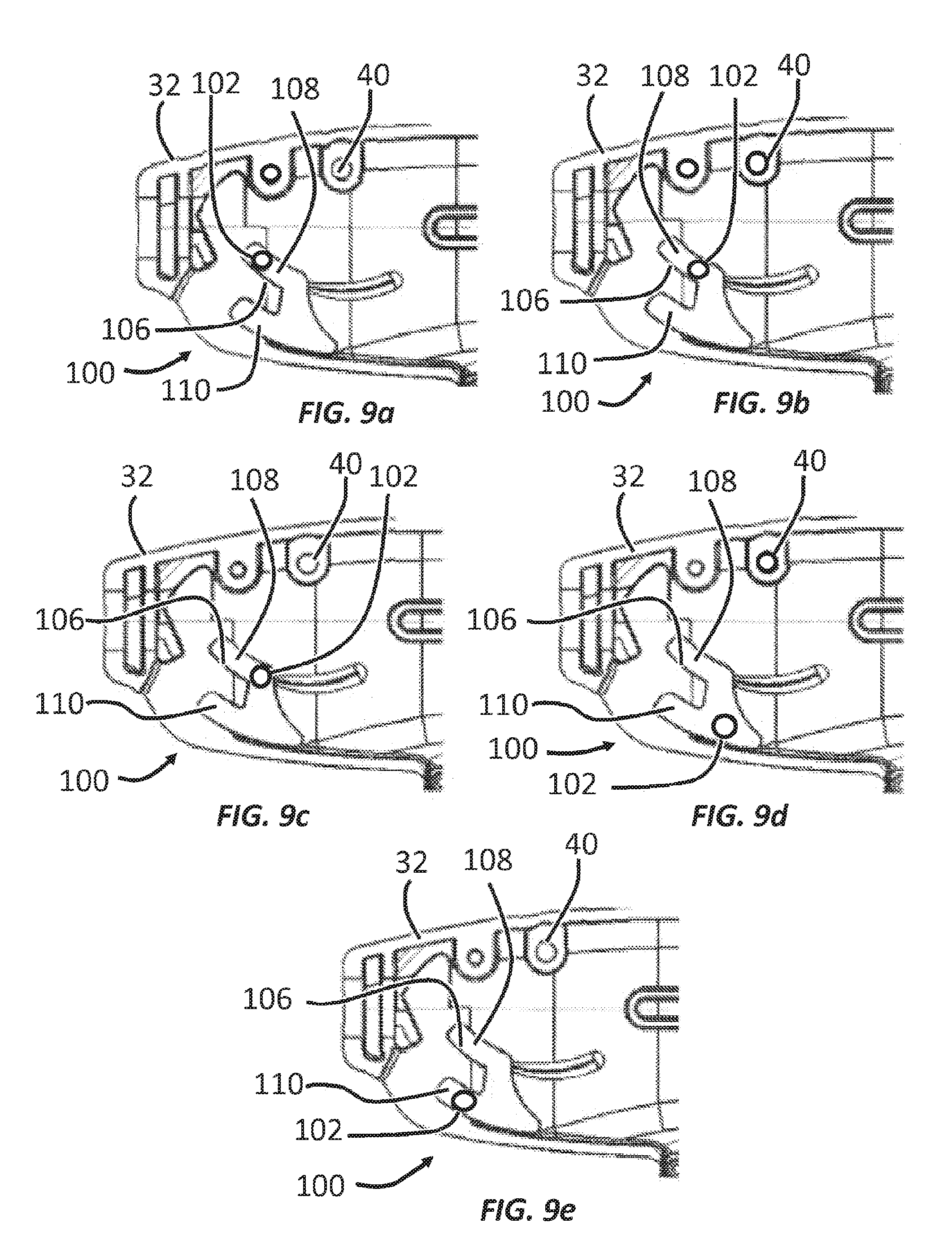
D00013
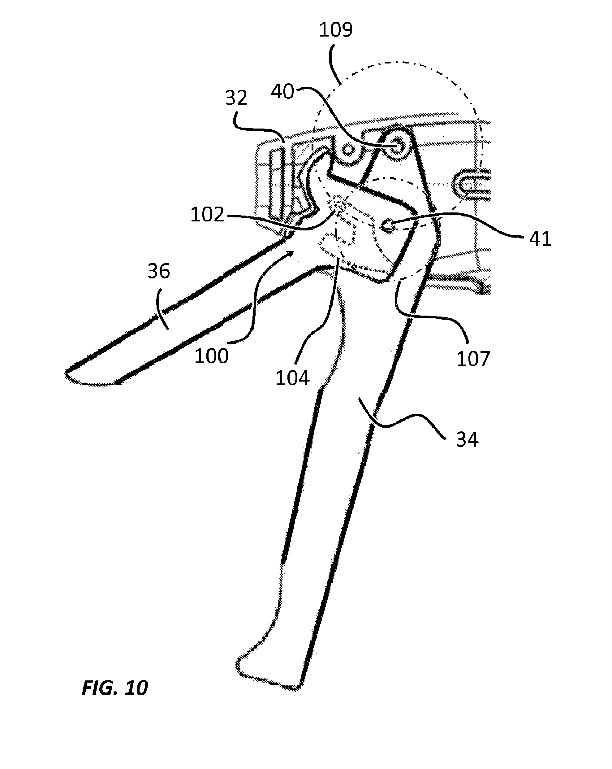
D00014
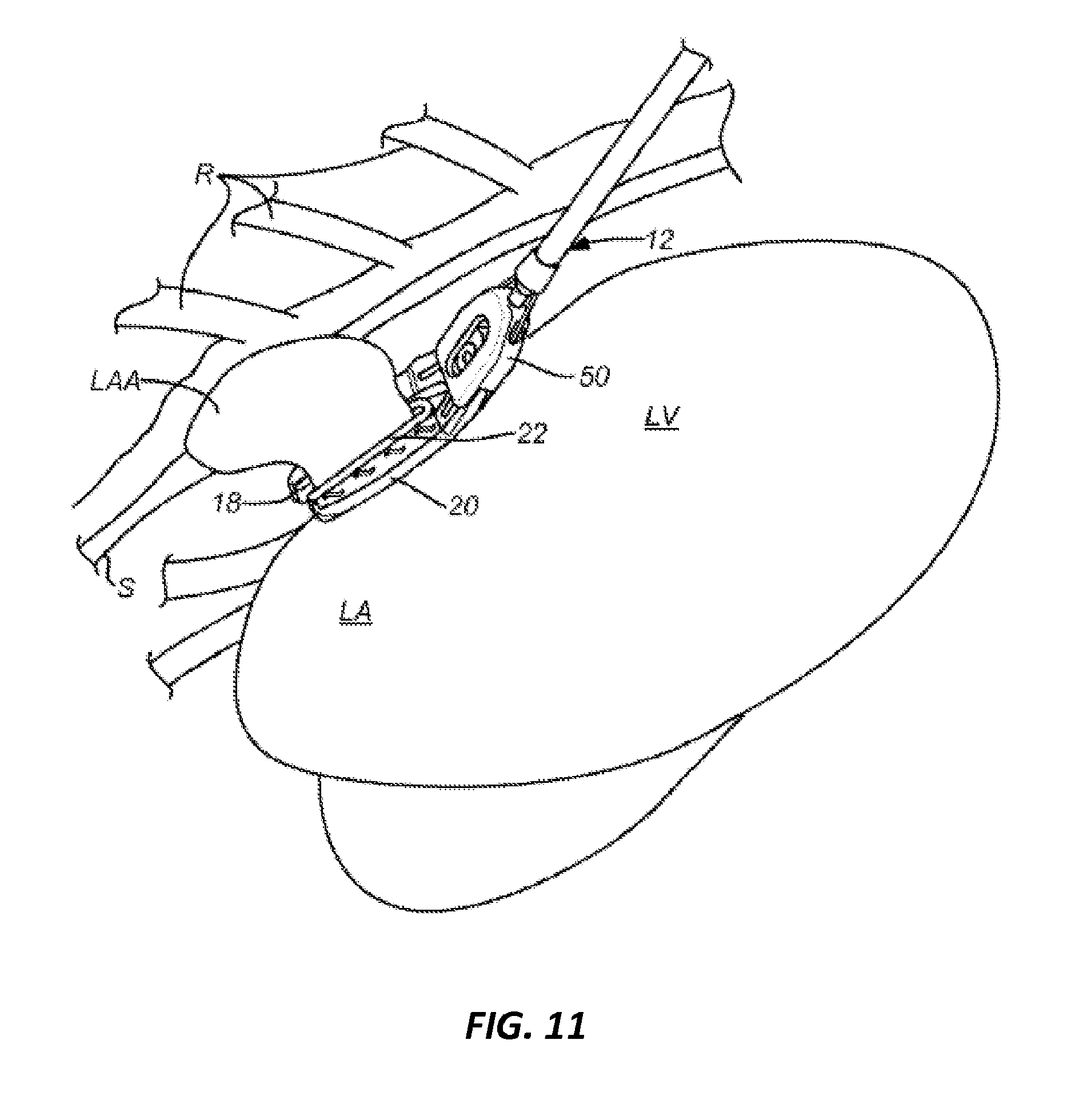
XML
uspto.report is an independent third-party trademark research tool that is not affiliated, endorsed, or sponsored by the United States Patent and Trademark Office (USPTO) or any other governmental organization. The information provided by uspto.report is based on publicly available data at the time of writing and is intended for informational purposes only.
While we strive to provide accurate and up-to-date information, we do not guarantee the accuracy, completeness, reliability, or suitability of the information displayed on this site. The use of this site is at your own risk. Any reliance you place on such information is therefore strictly at your own risk.
All official trademark data, including owner information, should be verified by visiting the official USPTO website at www.uspto.gov. This site is not intended to replace professional legal advice and should not be used as a substitute for consulting with a legal professional who is knowledgeable about trademark law.