Endoscopic surgical clip applier
Whitfield , et al. Nov
U.S. patent number 10,485,538 [Application Number 15/155,548] was granted by the patent office on 2019-11-26 for endoscopic surgical clip applier. This patent grant is currently assigned to Covidien LP. The grantee listed for this patent is Covidien LP. Invention is credited to Gregory Sorrentino, Kenneth H. Whitfield.


View All Diagrams
| United States Patent | 10,485,538 |
| Whitfield , et al. | November 26, 2019 |
Endoscopic surgical clip applier
Abstract
An apparatus for application of surgical clips to body tissue has a handle portion; a body extending distally from the handle portion; a plurality of surgical clips disposed within the body; and a jaw assembly mounted adjacent a distal end portion of the body. The jaw assembly includes first and second jaw portions movable between a spaced-apart and an approximated position. The apparatus also has a wedge plate longitudinally movable between the first and the second jaw portions, a clip pusher configured to individually distally advance a surgical clip to the jaw assembly while the jaw portions are in the spaced apart position; an actuator at least partially disposed within the body and longitudinally movable in response to actuation of the handle portion; and a jaw closure member positioned adjacent the first and second jaw portions to move the jaw portions to the approximated position.
| Inventors: | Whitfield; Kenneth H. (North Haven, CT), Sorrentino; Gregory (Wallingford, CT) | ||||||||||
|---|---|---|---|---|---|---|---|---|---|---|---|
| Applicant: |
|
||||||||||
| Assignee: | Covidien LP (Mansfield,
MA) |
||||||||||
| Family ID: | 36148936 | ||||||||||
| Appl. No.: | 15/155,548 | ||||||||||
| Filed: | May 16, 2016 |
Prior Publication Data
| Document Identifier | Publication Date | |
|---|---|---|
| US 20160256158 A1 | Sep 8, 2016 | |
Related U.S. Patent Documents
| Application Number | Filing Date | Patent Number | Issue Date | ||
|---|---|---|---|---|---|
| 14062338 | Oct 24, 2013 | 9364240 | |||
| 12780993 | Nov 12, 2013 | 8579918 | |||
| 11245528 | Mar 15, 2011 | 7905890 | |||
| 60617016 | Oct 8, 2004 | ||||
| 60617104 | Oct 8, 2004 | ||||
| Current U.S. Class: | 1/1 |
| Current CPC Class: | A61B 17/10 (20130101); A61B 17/00234 (20130101); A61B 17/105 (20130101); A61B 17/0682 (20130101); A61B 17/128 (20130101); A61B 17/122 (20130101); A61B 90/08 (20160201); A61B 17/1285 (20130101); A61B 2017/00115 (20130101); A61B 2017/00734 (20130101); A61B 2017/12004 (20130101); A61B 2017/2927 (20130101); A61B 2017/00778 (20130101); A61B 2090/0807 (20160201); A61B 2017/2926 (20130101); A61B 2017/00367 (20130101); A61B 2017/00407 (20130101); A61B 2017/2923 (20130101); A61B 2090/0811 (20160201); A61B 2090/0803 (20160201) |
| Current International Class: | A61B 17/068 (20060101); A61B 17/29 (20060101); A61B 17/12 (20060101); A61B 17/10 (20060101); A61B 17/128 (20060101); A61B 90/00 (20160101); A61B 17/00 (20060101); A61B 17/122 (20060101) |
References Cited [Referenced By]
U.S. Patent Documents
| 3120230 | February 1964 | Skold |
| 3363628 | January 1968 | Wood |
| 3638847 | February 1972 | Noiles et al. |
| 3675688 | July 1972 | Bryan et al. |
| 3867944 | February 1975 | Samuels |
| 4242902 | January 1981 | Green |
| 4296751 | October 1981 | Blake, III et al. |
| 4372316 | February 1983 | Blake, III et al. |
| 4408603 | October 1983 | Blake, III et al. |
| 4449531 | May 1984 | Cerwin et al. |
| 4478220 | October 1984 | Di Giovanni et al. |
| 4480640 | November 1984 | Becht |
| 4480641 | November 1984 | Failla et al. |
| 4487204 | December 1984 | Hrouda |
| 4487205 | December 1984 | Di Giovanni et al. |
| 4491133 | January 1985 | Menges et al. |
| 4492232 | January 1985 | Green |
| 4498476 | February 1985 | Cerwin et al. |
| 4500024 | February 1985 | DiGiovanni et al. |
| 4509518 | April 1985 | McGarry et al. |
| 4512345 | April 1985 | Green |
| 4522207 | June 1985 | Klieman et al. |
| 4532925 | August 1985 | Blake, III |
| 4534351 | August 1985 | Rothfuss et al. |
| 4545377 | October 1985 | Cerwin et al. |
| 4549544 | October 1985 | Favaron |
| 4556058 | December 1985 | Green |
| 4557263 | December 1985 | Green |
| 4562839 | January 1986 | Blake, III et al. |
| 4572183 | February 1986 | Juska |
| 4576165 | March 1986 | Green et al. |
| 4576166 | March 1986 | Montgomery et al. |
| 4590937 | May 1986 | Deniega |
| 4592498 | June 1986 | Braun et al. |
| 4598711 | July 1986 | Deniega |
| 4602631 | July 1986 | Funatsu |
| 4611595 | September 1986 | Klieman et al. |
| 4612932 | September 1986 | Caspar et al. |
| 4616650 | October 1986 | Green et al. |
| 4616651 | October 1986 | Golden |
| 4624254 | November 1986 | McGarry et al. |
| 4637395 | January 1987 | Caspar et al. |
| 4646740 | March 1987 | Peters et al. |
| 4647504 | March 1987 | Kimimura et al. |
| 4658822 | April 1987 | Kees, Jr. |
| 4660558 | April 1987 | Kees, Jr. |
| 4662373 | May 1987 | Montgomery et al. |
| 4662374 | May 1987 | Blake, III |
| 4671278 | June 1987 | Chin |
| 4671282 | June 1987 | Tretbar |
| 4674504 | June 1987 | Klieman et al. |
| 4681107 | July 1987 | Kees, Jr. |
| 4696396 | September 1987 | Samuels |
| 4702247 | October 1987 | Blake, III et al. |
| 4706668 | November 1987 | Backer |
| 4712549 | December 1987 | Peters et al. |
| 4733664 | March 1988 | Kirsch et al. |
| 4733666 | March 1988 | Mercer, Jr. |
| 4759364 | July 1988 | Boebel |
| 4765335 | August 1988 | Schmidt et al. |
| 4777949 | October 1988 | Perlin |
| 4777950 | October 1988 | Kees, Jr. |
| 4796625 | January 1989 | Kees, Jr. |
| 4799481 | January 1989 | Transue et al. |
| 4815466 | March 1989 | Perlin |
| 4817604 | April 1989 | Smith, III |
| 4821721 | April 1989 | Chin et al. |
| 4822348 | April 1989 | Casey |
| 4827930 | May 1989 | Kees, Jr. |
| 4834096 | May 1989 | Oh et al. |
| 4850355 | July 1989 | Brooks et al. |
| 4854317 | August 1989 | Braun |
| 4856517 | August 1989 | Collins et al. |
| 4929239 | May 1990 | Braun |
| 4929240 | May 1990 | Kirsch et al. |
| 4931058 | June 1990 | Cooper |
| 4932955 | June 1990 | Merz et al. |
| 4934364 | June 1990 | Green |
| 4943298 | July 1990 | Fujita et al. |
| 4951860 | August 1990 | Peters et al. |
| 4957500 | September 1990 | Liang et al. |
| 4966603 | October 1990 | Focelle et al. |
| 4967949 | November 1990 | Sandhaus |
| 4983176 | January 1991 | Cushman et al. |
| 4988355 | January 1991 | Leveen et al. |
| 5002552 | March 1991 | Casey |
| 5026379 | June 1991 | Yoon |
| 5030224 | July 1991 | Wright et al. |
| 5030226 | July 1991 | Green et al. |
| 5032127 | July 1991 | Frazee et al. |
| 5035692 | July 1991 | Lyon et al. |
| 5047038 | September 1991 | Peters et al. |
| 5049152 | September 1991 | Simon et al. |
| 5049153 | September 1991 | Nakao et al. |
| 5053045 | October 1991 | Schmidt et al. |
| 5059202 | October 1991 | Liang et al. |
| 5062563 | November 1991 | Green et al. |
| 5062846 | November 1991 | Oh et al. |
| 5078731 | January 1992 | Hayhurst |
| 5084057 | January 1992 | Green et al. |
| 5100416 | March 1992 | Oh et al. |
| 5100420 | March 1992 | Green et al. |
| 5104394 | April 1992 | Knoepfler |
| 5104395 | April 1992 | Thornton et al. |
| 5112343 | May 1992 | Thornton |
| 5122150 | June 1992 | Puig |
| 5127915 | July 1992 | Mattson |
| 5129885 | July 1992 | Green et al. |
| 5156608 | October 1992 | Troidl et al. |
| 5160339 | November 1992 | Chen et al. |
| 5163945 | November 1992 | Ortiz et al. |
| 5171247 | December 1992 | Hughett et al. |
| 5171249 | December 1992 | Stefanchik et al. |
| 5171250 | December 1992 | Yoon |
| 5171251 | December 1992 | Bregen et al. |
| 5171252 | December 1992 | Friedland |
| 5171253 | December 1992 | Klieman |
| 5192288 | March 1993 | Thompson et al. |
| 5197970 | March 1993 | Green et al. |
| 5199566 | April 1993 | Ortiz et al. |
| 5201746 | April 1993 | Shichman |
| 5201900 | April 1993 | Nardella |
| 5207691 | May 1993 | Nardella |
| 5207692 | May 1993 | Kraus et al. |
| 5217473 | June 1993 | Yoon |
| 5219353 | June 1993 | Garvey, III et al. |
| 5246450 | September 1993 | Thornton et al. |
| 5269792 | December 1993 | Kovac et al. |
| 5281228 | January 1994 | Wolfson |
| 5282807 | February 1994 | Knoepfler |
| 5282808 | February 1994 | Kovac et al. |
| 5282832 | February 1994 | Toso et al. |
| 5289963 | March 1994 | McGarry et al. |
| 5290299 | March 1994 | Fain et al. |
| 5300081 | April 1994 | Young et al. |
| 5304183 | April 1994 | Gourlay et al. |
| 5306280 | April 1994 | Bregen et al. |
| 5306283 | April 1994 | Conners |
| 5312426 | May 1994 | Segawa et al. |
| 5330442 | July 1994 | Green et al. |
| 5330487 | July 1994 | Thornton et al. |
| 5340360 | August 1994 | Stefanchik |
| 5342373 | August 1994 | Stefanchik et al. |
| 5354304 | October 1994 | Allen et al. |
| 5354306 | October 1994 | Garvey, III et al. |
| 5366458 | November 1994 | Korthoff et al. |
| 5366459 | November 1994 | Yoon |
| 5368600 | November 1994 | Failla et al. |
| 5381943 | January 1995 | Allen et al. |
| 5382253 | January 1995 | Hogendijk |
| 5382254 | January 1995 | McGarry et al. |
| 5382255 | January 1995 | Castro et al. |
| 5383880 | January 1995 | Hooven |
| 5383881 | January 1995 | Green et al. |
| 5395375 | March 1995 | Turkel et al. |
| 5395381 | March 1995 | Green et al. |
| 5403327 | April 1995 | Thornton et al. |
| 5409498 | April 1995 | Braddock et al. |
| 5413584 | May 1995 | Schulze |
| 5421835 | June 1995 | Harding |
| 5423835 | June 1995 | Green et al. |
| 5425740 | June 1995 | Hutchinson, Jr. |
| 5431667 | July 1995 | Thompson et al. |
| 5431668 | July 1995 | Burbank, III et al. |
| 5431669 | July 1995 | Thompson et al. |
| 5439468 | August 1995 | Schulze et al. |
| 5441509 | August 1995 | Vidal et al. |
| 5447513 | September 1995 | Davison et al. |
| 5449365 | September 1995 | Green et al. |
| 5462555 | October 1995 | Bolanos et al. |
| 5462558 | October 1995 | Kolesa et al. |
| 5464416 | November 1995 | Steckel |
| 5474566 | December 1995 | Alesi et al. |
| 5474567 | December 1995 | Stefanchik et al. |
| 5474572 | December 1995 | Hayhurst |
| 5487499 | January 1996 | Sorrentino et al. |
| 5487746 | January 1996 | Yu et al. |
| 5501693 | March 1996 | Gravener |
| 5509920 | April 1996 | Phillips et al. |
| 5514149 | May 1996 | Green et al. |
| 5520701 | May 1996 | Lerch |
| 5522823 | June 1996 | Kuntz et al. |
| 5527318 | June 1996 | McGarry |
| 5527319 | June 1996 | Green et al. |
| 5527320 | June 1996 | Carruthers et al. |
| 5542949 | August 1996 | Yoon |
| 5547474 | August 1996 | Kloeckl et al. |
| 5569274 | October 1996 | Rapacki et al. |
| 5571121 | November 1996 | Heifetz |
| 5575802 | November 1996 | McQuilkin et al. |
| 5582615 | December 1996 | Foshee et al. |
| 5584840 | December 1996 | Ramsey et al. |
| 5591178 | January 1997 | Green et al. |
| 5593414 | January 1997 | Shipp et al. |
| 5593421 | January 1997 | Bauer |
| 5601573 | February 1997 | Fogelberg et al. |
| 5601574 | February 1997 | Stefanchik et al. |
| 5607436 | March 1997 | Pratt et al. |
| 5618291 | April 1997 | Thompson et al. |
| 5618306 | April 1997 | Roth et al. |
| 5620452 | April 1997 | Yoon |
| 5626585 | May 1997 | Mittelstadt et al. |
| 5626586 | May 1997 | Pistl et al. |
| 5626587 | May 1997 | Bishop et al. |
| 5626592 | May 1997 | Phillips et al. |
| RE35525 | June 1997 | Stefanchik et al. |
| 5634930 | June 1997 | Thornton et al. |
| 5643291 | July 1997 | Pier et al. |
| 5645551 | July 1997 | Green et al. |
| 5645553 | July 1997 | Kolesa et al. |
| 5649937 | July 1997 | Bito et al. |
| 5653720 | August 1997 | Johnson et al. |
| 5662662 | September 1997 | Bishop et al. |
| 5662676 | September 1997 | Koninckx |
| 5662679 | September 1997 | Voss et al. |
| 5665097 | September 1997 | Baker et al. |
| 5676676 | October 1997 | Porter |
| 5681330 | October 1997 | Hughett et al. |
| 5683405 | November 1997 | Yacoubian et al. |
| 5695502 | December 1997 | Pier et al. |
| 5695505 | December 1997 | Yoon |
| 5697938 | December 1997 | Jensen et al. |
| 5700270 | December 1997 | Peyser et al. |
| 5700271 | December 1997 | Whitfield et al. |
| 5702048 | December 1997 | Eberlin |
| 5709706 | January 1998 | Kienzle et al. |
| 5713911 | February 1998 | Racenet et al. |
| 5713912 | February 1998 | Porter |
| 5720756 | February 1998 | Green et al. |
| 5722982 | March 1998 | Ferreira et al. |
| 5725537 | March 1998 | Green et al. |
| 5725538 | March 1998 | Green et al. |
| 5725542 | March 1998 | Yoon |
| 5733295 | March 1998 | Back et al. |
| 5749881 | May 1998 | Sackier et al. |
| 5755726 | May 1998 | Pratt et al. |
| 5766189 | June 1998 | Matsuno |
| 5769857 | June 1998 | Reztzov et al. |
| 5772673 | June 1998 | Cuny et al. |
| 5776146 | July 1998 | Sackier et al. |
| 5776147 | July 1998 | Dolendo |
| 5779718 | July 1998 | Green et al. |
| 5779720 | July 1998 | Walder-Utz et al. |
| 5782844 | July 1998 | Yoon et al. |
| 5788698 | August 1998 | Savornin |
| 5792149 | August 1998 | Sherts et al. |
| 5792150 | August 1998 | Pratt et al. |
| 5797922 | August 1998 | Hessel et al. |
| 5810853 | September 1998 | Yoon |
| 5817116 | October 1998 | Takahashi et al. |
| 5827306 | October 1998 | Yoon |
| 5827323 | October 1998 | Klieman et al. |
| 5833695 | November 1998 | Yoon |
| 5833696 | November 1998 | Whitfield |
| 5833700 | November 1998 | Fogelberg et al. |
| 5843097 | December 1998 | Mayenberger et al. |
| 5843101 | December 1998 | Fry |
| 5846255 | December 1998 | Casey |
| 5849019 | December 1998 | Yoon |
| 5858018 | January 1999 | Shipp et al. |
| 5861005 | January 1999 | Kontos |
| 5868759 | February 1999 | Peyser et al. |
| 5868761 | February 1999 | Nicholas et al. |
| 5876410 | March 1999 | Petillo |
| 5895394 | April 1999 | Kienzle et al. |
| 5897565 | April 1999 | Foster |
| 5904693 | May 1999 | Dicesare et al. |
| 5906625 | May 1999 | Bito et al. |
| 5913862 | June 1999 | Ramsey et al. |
| 5918791 | July 1999 | Sorrentino et al. |
| 5921996 | July 1999 | Sherman |
| 5921997 | July 1999 | Fogelberg et al. |
| 5928251 | July 1999 | Aranyi et al. |
| 5938667 | August 1999 | Peyser et al. |
| 5951574 | September 1999 | Stefanchik et al. |
| 5972003 | October 1999 | Rousseau et al. |
| 5976159 | November 1999 | Bolduc et al. |
| 5993465 | November 1999 | Shipp et al. |
| 6004335 | December 1999 | Vaitekunas et al. |
| 6016448 | January 2000 | Busacker et al. |
| 6017358 | January 2000 | Yoon et al. |
| 6045560 | April 2000 | McKean et al. |
| RE36720 | May 2000 | Green et al. |
| 6059799 | May 2000 | Aranyi et al. |
| 6099536 | August 2000 | Petillo |
| 6099537 | August 2000 | Sugai et al. |
| 6139555 | October 2000 | Hart et al. |
| 6210418 | April 2001 | Storz et al. |
| 6217590 | April 2001 | Levinson |
| 6228097 | May 2001 | Levinson et al. |
| 6241740 | June 2001 | Davis et al. |
| 6258105 | July 2001 | Hart et al. |
| 6261302 | July 2001 | Voegele et al. |
| 6273898 | August 2001 | Kienzle et al. |
| 6277131 | August 2001 | Kalikow |
| 6306149 | October 2001 | Meade |
| 6318619 | November 2001 | Lee |
| 6322571 | November 2001 | Adams |
| 6350269 | February 2002 | Shipp et al. |
| 6352541 | March 2002 | Kienzle et al. |
| 6391035 | May 2002 | Appleby et al. |
| 6423079 | July 2002 | Blake, III |
| 6428548 | August 2002 | Durgin et al. |
| 6440144 | August 2002 | Bacher |
| 6461363 | October 2002 | Gadberry et al. |
| 6464710 | October 2002 | Foster |
| 6494886 | December 2002 | Wilk et al. |
| 6517536 | February 2003 | Hooven et al. |
| 6520972 | February 2003 | Peters |
| 6527786 | March 2003 | Davis et al. |
| 6537289 | March 2003 | Kayan et al. |
| 6546935 | April 2003 | Hooven |
| 6551333 | April 2003 | Kuhns et al. |
| 6562051 | May 2003 | Bolduc et al. |
| 6569171 | May 2003 | DeGuillebon et al. |
| 6579304 | June 2003 | Hart et al. |
| 6599298 | July 2003 | Forster et al. |
| 6602252 | August 2003 | Mollenauer |
| 6607540 | August 2003 | Shipp |
| 6613060 | September 2003 | Adams et al. |
| 6626916 | September 2003 | Yeung et al. |
| 6626922 | September 2003 | Hart et al. |
| 6648898 | November 2003 | Baxter |
| 6652538 | November 2003 | Kayan et al. |
| 6652539 | November 2003 | Shipp et al. |
| 6656193 | December 2003 | Grant et al. |
| 6673083 | January 2004 | Kayan et al. |
| 6676659 | January 2004 | Hutchins et al. |
| 6679894 | January 2004 | Damarati |
| RE38445 | February 2004 | Pistl et al. |
| 6695854 | February 2004 | Kayan et al. |
| 6706057 | March 2004 | Bidoia et al. |
| 6716226 | April 2004 | Sixto, Jr. et al. |
| 6723109 | April 2004 | Solingen |
| 6743240 | June 2004 | Smith et al. |
| 6773438 | August 2004 | Knodel et al. |
| 6773440 | August 2004 | Gannoe et al. |
| 6776783 | August 2004 | Frantzen et al. |
| 6776784 | August 2004 | Ginn |
| 6780195 | August 2004 | Porat |
| 6793663 | September 2004 | Kneifel et al. |
| 6793664 | September 2004 | Mazzocchi et al. |
| 6802848 | October 2004 | Anderson et al. |
| 6814742 | November 2004 | Kimura et al. |
| 6818009 | November 2004 | Hart et al. |
| 6821273 | November 2004 | Mollenauer |
| 6821284 | November 2004 | Sturtz et al. |
| 6824547 | November 2004 | Wilson, Jr. et al. |
| 6824548 | November 2004 | Smith et al. |
| 6835199 | December 2004 | McGuckin, Jr. et al. |
| 6835200 | December 2004 | Laufer et al. |
| 6837893 | January 2005 | Miller |
| 6837894 | January 2005 | Pugsley, Jr. et al. |
| 6837895 | January 2005 | Mayenberger |
| 6840945 | January 2005 | Manetakis et al. |
| 6843794 | January 2005 | Sixto, Jr. et al. |
| 6849078 | February 2005 | Durgin et al. |
| 6849079 | February 2005 | Blake, III et al. |
| 6853879 | February 2005 | Sunaoshi |
| 6869435 | March 2005 | Blake, III |
| 6869436 | March 2005 | Wendlandt |
| 6889116 | May 2005 | Jinno |
| 6896682 | May 2005 | McClellan et al. |
| 6905503 | June 2005 | Gifford, III et al. |
| 6911032 | June 2005 | Jugenheimer et al. |
| 6911033 | June 2005 | de Guillebon et al. |
| 6913607 | July 2005 | Ainsworth et al. |
| 6916327 | July 2005 | Northrup, III et al. |
| 6923818 | August 2005 | Muramatsu et al. |
| 6939356 | September 2005 | Debbas |
| 6942674 | September 2005 | Belef et al. |
| 6942676 | September 2005 | Buelna |
| 6945978 | September 2005 | Hyde |
| 6945979 | September 2005 | Kortenbach et al. |
| 6949107 | September 2005 | McGuckin, Jr. et al. |
| 6953465 | October 2005 | Dieck et al. |
| 6955643 | October 2005 | Gellman et al. |
| 6959852 | November 2005 | Shelton, IV et al. |
| 6960218 | November 2005 | Rennich |
| 6960221 | November 2005 | Ho et al. |
| 6962594 | November 2005 | Thevenet |
| 6963792 | November 2005 | Green |
| 6964363 | November 2005 | Wales et al. |
| 6964668 | November 2005 | Modesitt et al. |
| 6966875 | November 2005 | Longobardi |
| 6966917 | November 2005 | Suyker et al. |
| 6966919 | November 2005 | Sixto, Jr. et al. |
| 6969391 | November 2005 | Gazzani |
| 6972023 | December 2005 | Whayne et al. |
| 6972027 | December 2005 | Fallin et al. |
| 6973770 | December 2005 | Schnipke et al. |
| 6974462 | December 2005 | Sater |
| 6974466 | December 2005 | Ahmed et al. |
| 6974475 | December 2005 | Wall |
| 6981505 | January 2006 | Krause et al. |
| 6981628 | January 2006 | Wales |
| 6991635 | January 2006 | Takamoto et al. |
| 7052504 | May 2006 | Hughett |
| 7056330 | June 2006 | Gayton |
| 7108703 | September 2006 | Danitz et al. |
| 7118564 | October 2006 | Ritchie et al. |
| 7144402 | December 2006 | Kuester, III |
| 7175648 | February 2007 | Nakao |
| 7179265 | February 2007 | Manetakis et al. |
| 7207997 | April 2007 | Shipp et al. |
| 7211091 | May 2007 | Fowler et al. |
| 7211092 | May 2007 | Hughett |
| 7214230 | May 2007 | Brock et al. |
| 7214232 | May 2007 | Bowman et al. |
| 7223271 | May 2007 | Muramatsu et al. |
| 7223272 | May 2007 | Francese et al. |
| 7232445 | June 2007 | Kortenbach et al. |
| 7261724 | August 2007 | Molitor et al. |
| 7261725 | August 2007 | Binmoeller |
| 7264625 | September 2007 | Buncke |
| 7288098 | October 2007 | Huitema et al. |
| 7297149 | November 2007 | Vitali et al. |
| 7316693 | January 2008 | Viola |
| 7316696 | January 2008 | Wilson, Jr. et al. |
| 7326223 | February 2008 | Wilson, Jr. |
| 7329266 | February 2008 | Royse et al. |
| 7331968 | February 2008 | Arp et al. |
| 7338503 | March 2008 | Rosenberg et al. |
| 7357805 | April 2008 | Masuda et al. |
| 7510562 | March 2009 | Lindsay |
| 7552853 | June 2009 | Mas et al. |
| 7637917 | December 2009 | Whitfield et al. |
| 7644848 | January 2010 | Swayze et al. |
| 7686820 | March 2010 | Huitema et al. |
| 7695482 | April 2010 | Viola |
| 7717926 | May 2010 | Whitfield et al. |
| 7727248 | June 2010 | Smith et al. |
| 7731724 | June 2010 | Huitema et al. |
| 7740641 | June 2010 | Huitema |
| 7752853 | July 2010 | Singh et al. |
| 7753250 | July 2010 | Clauson et al. |
| 7766207 | August 2010 | Mather et al. |
| 7819886 | October 2010 | Whitfield et al. |
| 7887553 | February 2011 | Lehman et al. |
| 7905890 | March 2011 | Whitfield et al. |
| 7942885 | May 2011 | Sixto, Jr. et al. |
| 7952060 | May 2011 | Watanabe et al. |
| 7963433 | June 2011 | Whitman et al. |
| 7988027 | August 2011 | Olson et al. |
| 8011550 | September 2011 | Aranyi et al. |
| 8011555 | September 2011 | Tarinelli et al. |
| 8016178 | September 2011 | Olson et al. |
| 8021375 | September 2011 | Aldrich et al. |
| 8021378 | September 2011 | Sixto, Jr. et al. |
| 8038686 | October 2011 | Huitema et al. |
| 8056565 | November 2011 | Zergiebel |
| 8062310 | November 2011 | Shibata et al. |
| 8066720 | November 2011 | Knodel et al. |
| 8066721 | November 2011 | Kortenbach et al. |
| 8066722 | November 2011 | Miyagi et al. |
| 8070760 | December 2011 | Fujita |
| 8075571 | December 2011 | Vitali et al. |
| 8080021 | December 2011 | Griego |
| 8083668 | December 2011 | Durgin et al. |
| 8088061 | January 2012 | Wells et al. |
| 8091755 | January 2012 | Kayan et al. |
| 8100926 | January 2012 | Filshie et al. |
| 8128643 | March 2012 | Aranyi et al. |
| 8133240 | March 2012 | Damarati |
| 8142451 | March 2012 | Boulnois et al. |
| 8157145 | April 2012 | Shelton, IV et al. |
| 8157149 | April 2012 | Olson et al. |
| 8157151 | April 2012 | Ingmanson et al. |
| 8172859 | May 2012 | Matsuno et al. |
| 8172870 | May 2012 | Shipp |
| 8187290 | May 2012 | Buckman et al. |
| 8211120 | July 2012 | Itoh |
| 8211124 | July 2012 | Ainsworth et al. |
| 8216255 | July 2012 | Smith et al. |
| 8216257 | July 2012 | Huitema et al. |
| 8236012 | August 2012 | Molitor et al. |
| 8246634 | August 2012 | Huitema et al. |
| 8246635 | August 2012 | Huitema |
| 8262678 | September 2012 | Matsuoka et al. |
| 8262679 | September 2012 | Nguyen |
| 8267944 | September 2012 | Sorrentino et al. |
| 8267945 | September 2012 | Nguyen et al. |
| 8267946 | September 2012 | Whitfield et al. |
| 8272554 | September 2012 | Whitman et al. |
| 8282655 | October 2012 | Whitfield et al. |
| 8308743 | November 2012 | Matsuno et al. |
| 8328822 | December 2012 | Huitema et al. |
| 8336556 | December 2012 | Zergiebel |
| 8348130 | January 2013 | Shah et al. |
| 8357171 | January 2013 | Whitfield et al. |
| 8366709 | February 2013 | Schechter et al. |
| 8366726 | February 2013 | Dennis |
| 8371491 | February 2013 | Huitema et al. |
| 8372095 | February 2013 | Viola |
| 8382773 | February 2013 | Whitfield et al. |
| 8398655 | March 2013 | Cheng et al. |
| 8403945 | March 2013 | Whitfield et al. |
| 8403946 | March 2013 | Whitfield et al. |
| 8408442 | April 2013 | Racenet et al. |
| 8409222 | April 2013 | Whitfield et al. |
| 8409223 | April 2013 | Sorrentino et al. |
| 8419752 | April 2013 | Sorrentino et al. |
| 8430892 | April 2013 | Bindra et al. |
| 8444660 | May 2013 | Adams et al. |
| 8465460 | June 2013 | Yodfat et al. |
| 8465502 | June 2013 | Zergiebel |
| 8475473 | July 2013 | Vandenbroek et al. |
| 8480688 | July 2013 | Boulnois et al. |
| 8486091 | July 2013 | Sorrentino et al. |
| 8491608 | July 2013 | Sorrentino et al. |
| 8496673 | July 2013 | Nguyen et al. |
| 8506580 | August 2013 | Zergiebel et al. |
| 8512357 | August 2013 | Viola |
| 8518055 | August 2013 | Cardinale et al. |
| 8523882 | September 2013 | Huitema et al. |
| 8525687 | September 2013 | Tran |
| 8529585 | September 2013 | Jacobs et al. |
| 8529586 | September 2013 | Rosenberg et al. |
| 8529588 | September 2013 | Ahlberg et al. |
| 8545486 | October 2013 | Malkowski |
| 8556920 | October 2013 | Huitema et al. |
| 8568430 | October 2013 | Shipp |
| 8579918 | November 2013 | Whitfield et al. |
| 8585717 | November 2013 | Sorrentino et al. |
| 8603109 | December 2013 | Aranyi et al. |
| 8652151 | February 2014 | Lehman et al. |
| 8652152 | February 2014 | Aranyi et al. |
| 8663247 | March 2014 | Menn et al. |
| 8685048 | April 2014 | Adams et al. |
| 8690899 | April 2014 | Kogiso et al. |
| 8708213 | April 2014 | Shelton, IV et al. |
| 8709027 | April 2014 | Adams et al. |
| 8715299 | May 2014 | Menn et al. |
| 8720766 | May 2014 | Hess et al. |
| 8734469 | May 2014 | Pribanic et al. |
| 8747423 | June 2014 | Whitfield et al. |
| 8753356 | June 2014 | Vitali et al. |
| 8814884 | August 2014 | Whitfield et al. |
| 8821516 | September 2014 | Huitema |
| 8839954 | September 2014 | Disch |
| 8845659 | September 2014 | Whitfield et al. |
| 8894665 | November 2014 | Sorrentino et al. |
| 8894666 | November 2014 | Schulz et al. |
| 8900253 | December 2014 | Aranyi et al. |
| 8915930 | December 2014 | Huitema et al. |
| 8920438 | December 2014 | Aranyi et al. |
| 8950646 | February 2015 | Viola |
| 8961542 | February 2015 | Whitfield et al. |
| 8968337 | March 2015 | Whitfield et al. |
| 8968342 | March 2015 | Wingardner, III et al. |
| 8973804 | March 2015 | Hess et al. |
| 9011464 | April 2015 | Zammataro |
| 9011465 | April 2015 | Whitfield et al. |
| 9089334 | July 2015 | Sorrentino et al. |
| 9113892 | August 2015 | Malkowski et al. |
| 9113893 | August 2015 | Sorrentino et al. |
| 9119629 | September 2015 | Cardinale et al. |
| 9186136 | November 2015 | Malkowski et al. |
| 9186153 | November 2015 | Zammataro |
| 9208429 | December 2015 | Thornton et al. |
| 9220507 | December 2015 | Patel et al. |
| 9282961 | March 2016 | Whitman et al. |
| 9326776 | May 2016 | Gadberry et al. |
| 9358011 | June 2016 | Sorrentino et al. |
| 9358015 | June 2016 | Sorrentino et al. |
| 9364216 | June 2016 | Rockrohr et al. |
| 9364239 | June 2016 | Malkowski |
| 9364240 | June 2016 | Whitfield et al. |
| 9370400 | June 2016 | Parihar |
| 9393024 | July 2016 | Whitfield et al. |
| 9398917 | July 2016 | Whitfield et al. |
| 9408610 | August 2016 | Hartoumbekis |
| 9414844 | August 2016 | Zergiebel et al. |
| 9433411 | September 2016 | Racenet et al. |
| 9439654 | September 2016 | Sorrentino et al. |
| 9480477 | November 2016 | Aranyi et al. |
| 9498227 | November 2016 | Zergiebel et al. |
| 9526501 | December 2016 | Malkowski |
| 9532787 | January 2017 | Zammataro |
| 9545254 | January 2017 | Sorrentino et al. |
| 9549741 | January 2017 | Zergiebel |
| 9642627 | May 2017 | Zammataro |
| 9687247 | June 2017 | Aranyi et al. |
| 9717505 | August 2017 | Whitfield et al. |
| 9737310 | August 2017 | Whitfield et al. |
| 9750500 | September 2017 | Malkowski |
| 9763668 | September 2017 | Whitfield et al. |
| 9775623 | October 2017 | Zammataro et al. |
| 9775624 | October 2017 | Rockrohr et al. |
| 9848886 | December 2017 | Malkowski et al. |
| 9855043 | January 2018 | Malkowski |
| 9931124 | April 2018 | Gokharu |
| 9968361 | May 2018 | Aranyi et al. |
| 9968362 | May 2018 | Malkowski et al. |
| 2001/0047178 | November 2001 | Peters |
| 2002/0040226 | April 2002 | Laufer et al. |
| 2002/0068947 | June 2002 | Kuhns et al. |
| 2002/0082618 | June 2002 | Shipp et al. |
| 2002/0087169 | July 2002 | Brock et al. |
| 2002/0087170 | July 2002 | Kuhns et al. |
| 2002/0099388 | July 2002 | Mayenberger |
| 2002/0120279 | August 2002 | Deguillebon et al. |
| 2002/0128668 | September 2002 | Manetakis et al. |
| 2002/0177859 | November 2002 | Monassevitch et al. |
| 2002/0198537 | December 2002 | Smith et al. |
| 2002/0198538 | December 2002 | Kortenbach et al. |
| 2002/0198539 | December 2002 | Sixto et al. |
| 2002/0198540 | December 2002 | Smith et al. |
| 2002/0198541 | December 2002 | Smith et al. |
| 2003/0014060 | January 2003 | Wilson et al. |
| 2003/0018345 | January 2003 | Green |
| 2003/0023249 | January 2003 | Manetakis |
| 2003/0040759 | February 2003 | de Guillebon et al. |
| 2003/0105476 | June 2003 | Sancoff et al. |
| 2003/0114867 | June 2003 | Bolduc et al. |
| 2003/0135224 | July 2003 | Blake |
| 2003/0167063 | September 2003 | Kerr |
| 2003/0208231 | November 2003 | Williamson et al. |
| 2003/0225423 | December 2003 | Huitema |
| 2003/0233105 | December 2003 | Gayton |
| 2004/0010272 | January 2004 | Manetakis et al. |
| 2004/0097970 | May 2004 | Hughett |
| 2004/0097971 | May 2004 | Hughett |
| 2004/0138681 | July 2004 | Pier |
| 2004/0153100 | August 2004 | Ahlberg et al. |
| 2005/0010242 | January 2005 | Lindsay |
| 2005/0080440 | April 2005 | Durgin et al. |
| 2005/0085830 | April 2005 | Lehman et al. |
| 2005/0090837 | April 2005 | Sixto et al. |
| 2005/0090838 | April 2005 | Sixto et al. |
| 2005/0096670 | May 2005 | Wellman et al. |
| 2005/0096671 | May 2005 | Wellman et al. |
| 2005/0096672 | May 2005 | Manetakis et al. |
| 2005/0101975 | May 2005 | Nguyen et al. |
| 2005/0107807 | May 2005 | Nakao |
| 2005/0107809 | May 2005 | Litscher et al. |
| 2005/0107810 | May 2005 | Morales et al. |
| 2005/0107811 | May 2005 | Starksen et al. |
| 2005/0107812 | May 2005 | Starksen et al. |
| 2005/0107871 | May 2005 | Realyvasquez et al. |
| 2005/0113815 | May 2005 | Ritchie et al. |
| 2005/0113847 | May 2005 | Gadberry et al. |
| 2005/0116673 | June 2005 | Carl et al. |
| 2005/0119671 | June 2005 | Reydel et al. |
| 2005/0119673 | June 2005 | Gordon et al. |
| 2005/0119677 | June 2005 | Shipp |
| 2005/0125010 | June 2005 | Smith et al. |
| 2005/0143767 | June 2005 | Kimura et al. |
| 2005/0149063 | July 2005 | Young et al. |
| 2005/0149064 | July 2005 | Peterson et al. |
| 2005/0149068 | July 2005 | Williams et al. |
| 2005/0149069 | July 2005 | Bertolero et al. |
| 2005/0165415 | July 2005 | Wales |
| 2005/0165418 | July 2005 | Chan |
| 2005/0171560 | August 2005 | Hughett |
| 2005/0177176 | August 2005 | Gerbi et al. |
| 2005/0177177 | August 2005 | Viola |
| 2005/0203547 | September 2005 | Weller et al. |
| 2005/0203548 | September 2005 | Weller et al. |
| 2005/0216036 | September 2005 | Nakao |
| 2005/0216056 | September 2005 | Valdevit et al. |
| 2005/0222588 | October 2005 | Vandenbroek et al. |
| 2005/0222590 | October 2005 | Gadberry et al. |
| 2005/0222665 | October 2005 | Aranyi |
| 2005/0228411 | October 2005 | Manzo |
| 2005/0228416 | October 2005 | Burbank et al. |
| 2005/0234478 | October 2005 | Wixey et al. |
| 2005/0251183 | November 2005 | Buckman et al. |
| 2005/0251184 | November 2005 | Anderson |
| 2005/0256529 | November 2005 | Yawata et al. |
| 2005/0267495 | December 2005 | Ginn et al. |
| 2005/0273122 | December 2005 | Theroux et al. |
| 2005/0277951 | December 2005 | Smith et al. |
| 2005/0277952 | December 2005 | Arp et al. |
| 2005/0277953 | December 2005 | Francese et al. |
| 2005/0277954 | December 2005 | Smith et al. |
| 2005/0277955 | December 2005 | Palmer et al. |
| 2005/0277956 | December 2005 | Francese et al. |
| 2005/0277958 | December 2005 | Levinson |
| 2005/0288689 | December 2005 | Kammerer et al. |
| 2005/0288690 | December 2005 | Bourque et al. |
| 2006/0004388 | January 2006 | Whayne et al. |
| 2006/0004390 | January 2006 | Rosenberg et al. |
| 2006/0009789 | January 2006 | Gambale et al. |
| 2006/0009790 | January 2006 | Blake et al. |
| 2006/0009792 | January 2006 | Baker et al. |
| 2006/0020270 | January 2006 | Jabba et al. |
| 2006/0020271 | January 2006 | Stewart et al. |
| 2006/0047305 | March 2006 | Ortiz et al. |
| 2006/0047306 | March 2006 | Ortiz et al. |
| 2006/0064117 | March 2006 | Aranyi et al. |
| 2006/0079912 | April 2006 | Whitfield et al. |
| 2006/0079913 | April 2006 | Whitfield et al. |
| 2006/0085015 | April 2006 | Whitfield et al. |
| 2006/0100649 | May 2006 | Hart |
| 2006/0111731 | May 2006 | Manzo |
| 2006/0129170 | June 2006 | Royce et al. |
| 2006/0163312 | July 2006 | Viola et al. |
| 2006/0173470 | August 2006 | Oray et al. |
| 2006/0178683 | August 2006 | Shimoji et al. |
| 2006/0184182 | August 2006 | Aranyi et al. |
| 2006/0190013 | August 2006 | Menn |
| 2006/0195125 | August 2006 | Sakakine et al. |
| 2006/0200179 | September 2006 | Barker et al. |
| 2006/0217749 | September 2006 | Wilson et al. |
| 2006/0224170 | October 2006 | Duff |
| 2006/0235437 | October 2006 | Vitali et al. |
| 2006/0235438 | October 2006 | Huitema et al. |
| 2006/0235439 | October 2006 | Molitor et al. |
| 2006/0235440 | October 2006 | Huitema et al. |
| 2006/0235441 | October 2006 | Huitema et al. |
| 2006/0235442 | October 2006 | Huitema |
| 2006/0235443 | October 2006 | Huitema et al. |
| 2006/0235444 | October 2006 | Huitema et al. |
| 2006/0259045 | November 2006 | Damarati |
| 2006/0259049 | November 2006 | Harada et al. |
| 2006/0264987 | November 2006 | Sgro |
| 2006/0271072 | November 2006 | Hummel et al. |
| 2007/0016228 | January 2007 | Salas |
| 2007/0021761 | January 2007 | Phillips |
| 2007/0023476 | February 2007 | Whitman et al. |
| 2007/0023477 | February 2007 | Whitman et al. |
| 2007/0027458 | February 2007 | Sixto, Jr. et al. |
| 2007/0034669 | February 2007 | de la Torre et al. |
| 2007/0035203 | February 2007 | Bromfield |
| 2007/0038233 | February 2007 | Martinez et al. |
| 2007/0049947 | March 2007 | Menn et al. |
| 2007/0049948 | March 2007 | Menn et al. |
| 2007/0049949 | March 2007 | Manetakis |
| 2007/0049950 | March 2007 | Theroux et al. |
| 2007/0049951 | March 2007 | Menn |
| 2007/0049953 | March 2007 | Shimoji et al. |
| 2007/0073314 | March 2007 | Gadberry et al. |
| 2007/0083218 | April 2007 | Morris |
| 2007/0093856 | April 2007 | Whitfield et al. |
| 2007/0106314 | May 2007 | Dunn |
| 2007/0112365 | May 2007 | Hilal et al. |
| 2007/0118155 | May 2007 | Goldfarb et al. |
| 2007/0118161 | May 2007 | Kennedy et al. |
| 2007/0118163 | May 2007 | Boudreaux et al. |
| 2007/0118174 | May 2007 | Chu |
| 2007/0123916 | May 2007 | Maier et al. |
| 2007/0142848 | June 2007 | Ainsworth et al. |
| 2007/0142851 | June 2007 | Sixto et al. |
| 2007/0149988 | June 2007 | Michler et al. |
| 2007/0149989 | June 2007 | Santilli et al. |
| 2007/0162060 | July 2007 | Wild |
| 2007/0175949 | August 2007 | Shelton et al. |
| 2007/0185504 | August 2007 | Manetakis et al. |
| 2007/0191868 | August 2007 | Theroux et al. |
| 2007/0213747 | September 2007 | Monassevitch et al. |
| 2007/0250080 | October 2007 | Jones et al. |
| 2007/0265640 | November 2007 | Kortenbach et al. |
| 2007/0276417 | November 2007 | Mendes, Jr. et al. |
| 2007/0282355 | December 2007 | Brown et al. |
| 2007/0293875 | December 2007 | Soetikno et al. |
| 2008/0004636 | January 2008 | Walberg et al. |
| 2008/0004637 | January 2008 | Klassen et al. |
| 2008/0004639 | January 2008 | Huitema et al. |
| 2008/0015615 | January 2008 | Molitor et al. |
| 2008/0027465 | January 2008 | Vitali et al. |
| 2008/0027466 | January 2008 | Vitali et al. |
| 2008/0045981 | February 2008 | Margolin et al. |
| 2008/0051808 | February 2008 | Rivera et al. |
| 2008/0065118 | March 2008 | Damarati |
| 2008/0065119 | March 2008 | Viola |
| 2008/0083813 | April 2008 | Zemlok et al. |
| 2008/0103510 | May 2008 | Taylor et al. |
| 2008/0147092 | June 2008 | Rogge et al. |
| 2008/0147093 | June 2008 | Roskopf et al. |
| 2008/0154287 | June 2008 | Rosenberg et al. |
| 2008/0167665 | July 2008 | Arp et al. |
| 2008/0167671 | July 2008 | Giordano et al. |
| 2008/0228199 | September 2008 | Cropper et al. |
| 2008/0243145 | October 2008 | Whitfield et al. |
| 2008/0255413 | October 2008 | Zemlok et al. |
| 2008/0255589 | October 2008 | Blakeney et al. |
| 2008/0306492 | December 2008 | Shibata et al. |
| 2008/0306493 | December 2008 | Shibata et al. |
| 2008/0312665 | December 2008 | Shibata et al. |
| 2008/0312670 | December 2008 | Lutze et al. |
| 2008/0319456 | December 2008 | Hart |
| 2009/0076533 | March 2009 | Kayan et al. |
| 2009/0088777 | April 2009 | Miyagi et al. |
| 2009/0088783 | April 2009 | Kennedy et al. |
| 2009/0171380 | July 2009 | Whiting |
| 2009/0182193 | July 2009 | Whitman et al. |
| 2009/0209946 | August 2009 | Swayze et al. |
| 2009/0222003 | September 2009 | Otley |
| 2009/0228023 | September 2009 | Cui |
| 2009/0228024 | September 2009 | Whitfield et al. |
| 2009/0264904 | October 2009 | Aldrich et al. |
| 2009/0299382 | December 2009 | Zergiebel |
| 2009/0326558 | December 2009 | Cui et al. |
| 2010/0049216 | February 2010 | Zergiebel |
| 2010/0057105 | March 2010 | Sorrentino et al. |
| 2010/0057107 | March 2010 | Sorrentino et al. |
| 2010/0069935 | March 2010 | Crainich |
| 2010/0274262 | October 2010 | Schulz et al. |
| 2010/0274264 | October 2010 | Schulz et al. |
| 2011/0054498 | March 2011 | Monassevitch et al. |
| 2011/0082474 | April 2011 | Bindra et al. |
| 2011/0087241 | April 2011 | Nguyen |
| 2011/0087242 | April 2011 | Pribanic et al. |
| 2011/0087243 | April 2011 | Nguyen et al. |
| 2011/0112552 | May 2011 | Lehman et al. |
| 2011/0137323 | June 2011 | Malkowski et al. |
| 2011/0137324 | June 2011 | Boudreaux et al. |
| 2011/0144662 | June 2011 | McLawhorn et al. |
| 2011/0144665 | June 2011 | Malkowski |
| 2011/0190791 | August 2011 | Jacobs et al. |
| 2011/0208211 | August 2011 | Whitfield et al. |
| 2011/0208212 | August 2011 | Zergiebel et al. |
| 2011/0218553 | September 2011 | Huitema et al. |
| 2011/0218554 | September 2011 | Cheng et al. |
| 2011/0218555 | September 2011 | Huitema |
| 2011/0218556 | September 2011 | Nguyen et al. |
| 2011/0224696 | September 2011 | Huitema et al. |
| 2011/0224700 | September 2011 | Schmidt et al. |
| 2011/0224701 | September 2011 | Menn |
| 2011/0230900 | September 2011 | Sarradon |
| 2011/0245847 | October 2011 | Menn et al. |
| 2011/0245848 | October 2011 | Rosenberg et al. |
| 2011/0251608 | October 2011 | Timm et al. |
| 2011/0295290 | December 2011 | Whitfield |
| 2011/0313437 | December 2011 | Yeh |
| 2012/0029534 | February 2012 | Whitfield et al. |
| 2012/0041455 | February 2012 | Martinez |
| 2012/0046671 | February 2012 | Matsuoka et al. |
| 2012/0048759 | March 2012 | Disch et al. |
| 2012/0053402 | March 2012 | Conlon et al. |
| 2012/0059394 | March 2012 | Brenner et al. |
| 2012/0065647 | March 2012 | Litscher et al. |
| 2012/0109158 | May 2012 | Zammataro |
| 2012/0116420 | May 2012 | Sorrentino et al. |
| 2012/0123446 | May 2012 | Aranyi et al. |
| 2012/0143211 | June 2012 | Kishi |
| 2012/0197269 | August 2012 | Zammataro |
| 2012/0265220 | October 2012 | Menn |
| 2012/0277765 | November 2012 | Zammataro et al. |
| 2012/0310259 | December 2012 | Sorrentino et al. |
| 2012/0330326 | December 2012 | Creston et al. |
| 2013/0110135 | May 2013 | Whitfield et al. |
| 2013/0131697 | May 2013 | Hartoumbekis |
| 2013/0165951 | June 2013 | Blake, III |
| 2013/0165952 | June 2013 | Whitfield et al. |
| 2013/0172909 | July 2013 | Harris |
| 2013/0172910 | July 2013 | Malkowski |
| 2013/0172911 | July 2013 | Rockrohr et al. |
| 2013/0172912 | July 2013 | Whitfield et al. |
| 2013/0190779 | July 2013 | Whitfield et al. |
| 2013/0190780 | July 2013 | Whitfield et al. |
| 2013/0193898 | August 2013 | Williams et al. |
| 2013/0253541 | September 2013 | Zergiebel |
| 2013/0274767 | October 2013 | Sorrentino et al. |
| 2013/0289583 | October 2013 | Zergiebel et al. |
| 2013/0296891 | November 2013 | Hartoumbekis |
| 2013/0296892 | November 2013 | Sorrentino et al. |
| 2013/0310849 | November 2013 | Malkowski |
| 2013/0325040 | December 2013 | Zammataro |
| 2014/0005693 | January 2014 | Shelton, IV et al. |
| 2014/0039526 | February 2014 | Malkowski |
| 2014/0052157 | February 2014 | Whitfield et al. |
| 2014/0058412 | February 2014 | Aranyi et al. |
| 2014/0110453 | April 2014 | Wingardner et al. |
| 2014/0194903 | July 2014 | Malkowski et al. |
| 2014/0207156 | July 2014 | Malkowski |
| 2014/0263565 | September 2014 | Lytle, IV et al. |
| 2014/0296879 | October 2014 | Menn et al. |
| 2014/0316441 | October 2014 | Zergiebel et al. |
| 2014/0330291 | November 2014 | Whitfield et al. |
| 2015/0005790 | January 2015 | Whitfield et al. |
| 2015/0032131 | January 2015 | Sorrentino et al. |
| 2015/0045816 | February 2015 | Aranyi et al. |
| 2015/0066057 | March 2015 | Rockrohr et al. |
| 2015/0080916 | March 2015 | Aranyi et al. |
| 2015/0127022 | May 2015 | Whitfield et al. |
| 2015/0164511 | June 2015 | Whitfield et al. |
| 2015/0190138 | July 2015 | Whitfield et al. |
| 2015/0190139 | July 2015 | Zammataro |
| 2015/0282808 | October 2015 | Sorrentino et al. |
| 2015/0351771 | December 2015 | Malkowski et al. |
| 2015/0351772 | December 2015 | Malkowski et al. |
| 2016/0030044 | February 2016 | Zammataro |
| 2016/0030045 | February 2016 | Malkowski et al. |
| 2016/0113655 | April 2016 | Holsten |
| 2016/0151071 | June 2016 | Tokarz et al. |
| 2016/0192940 | July 2016 | Gokharu |
| 2016/0213377 | July 2016 | Shankarsetty |
| 2016/0242767 | August 2016 | Kasvikis |
| 2016/0242789 | August 2016 | Sorrentino et al. |
| 2016/0256157 | September 2016 | Rockrohr et al. |
| 2016/0256158 | September 2016 | Whitfield et al. |
| 2016/0262764 | September 2016 | Gokharu |
| 2016/0296236 | October 2016 | Whitfield et al. |
| 2016/0338695 | November 2016 | Hartoumbekis |
| 2016/0338699 | November 2016 | Sorrentino et al. |
| 2017/0027581 | February 2017 | Zergiebel et al. |
| 2017/0128071 | May 2017 | Holsten et al. |
| 2017/0172780 | June 2017 | Murthy Aravalli |
| 2017/0238936 | August 2017 | Mujawar |
| 2017/0258472 | September 2017 | Aranyi et al. |
| 2017/0325814 | November 2017 | Malkowski |
| 2017/0340325 | November 2017 | Baril et al. |
| 2017/0340331 | November 2017 | Hu et al. |
| 2017/0340332 | November 2017 | Whitfield et al. |
| 2017/0360449 | December 2017 | Rockrohr et al. |
| 2018/0008276 | January 2018 | Bhatnagar et al. |
| 2018/0008277 | January 2018 | Baril |
| 2018/0070952 | March 2018 | Malkowski et al. |
| 2018/0116671 | May 2018 | Prior |
| 2018/0116673 | May 2018 | Baril et al. |
| 2018/0116674 | May 2018 | Baril |
| 2018/0116675 | May 2018 | Baril |
| 2018/0116676 | May 2018 | Williams |
| 2010200641 | Oct 2010 | AU | |||
| 2013254887 | Nov 2013 | AU | |||
| 1163889 | Mar 1984 | CA | |||
| 2740831 | Apr 2010 | CA | |||
| 1994236 | Jul 2007 | CN | |||
| 101401737 | Apr 2009 | CN | |||
| 101530340 | Sep 2009 | CN | |||
| 100571640 | Dec 2009 | CN | |||
| 101658437 | Mar 2010 | CN | |||
| 101664329 | Mar 2010 | CN | |||
| 101664331 | Mar 2010 | CN | |||
| 201683954 | Dec 2010 | CN | |||
| 103083059 | May 2013 | CN | |||
| 103181809 | Jul 2013 | CN | |||
| 103181810 | Jul 2013 | CN | |||
| 104487006 | Apr 2015 | CN | |||
| 104605911 | Feb 2017 | CN | |||
| 202007003398 | Jun 2007 | DE | |||
| 202009006113 | Jul 2009 | DE | |||
| 0000756 | Feb 1979 | EP | |||
| 0073655 | Mar 1983 | EP | |||
| 0085931 | Aug 1983 | EP | |||
| 0086721 | Aug 1983 | EP | |||
| 0089737 | Sep 1983 | EP | |||
| 0092300 | Oct 1983 | EP | |||
| 0324166 | Jul 1989 | EP | |||
| 0392750 | Oct 1990 | EP | |||
| 0406724 | Jan 1991 | EP | |||
| 0409569 | Jan 1991 | EP | |||
| 0514139 | Mar 1993 | EP | |||
| 0569223 | Nov 1993 | EP | |||
| 0598529 | May 1994 | EP | |||
| 0 622 049 | Nov 1994 | EP | |||
| 0685204 | Dec 1995 | EP | |||
| 0732078 | Sep 1996 | EP | |||
| 0755655 | Jan 1997 | EP | |||
| 0 760 230 | Mar 1997 | EP | |||
| 0769274 | Apr 1997 | EP | |||
| 0769275 | Apr 1997 | EP | |||
| 0834286 | Apr 1998 | EP | |||
| 1317906 | Jun 2003 | EP | |||
| 1 468 653 | Oct 2004 | EP | |||
| 1609427 | Dec 2005 | EP | |||
| 1712187 | Oct 2006 | EP | |||
| 1712191 | Oct 2006 | EP | |||
| 1757236 | Feb 2007 | EP | |||
| 1 813 207 | Aug 2007 | EP | |||
| 1813199 | Aug 2007 | EP | |||
| 1894531 | Mar 2008 | EP | |||
| 1908423 | Apr 2008 | EP | |||
| 1913881 | Apr 2008 | EP | |||
| 1939231 | Jul 2008 | EP | |||
| 1943956 | Jul 2008 | EP | |||
| 1980215 | Oct 2008 | EP | |||
| 2 000 102 | Dec 2008 | EP | |||
| 2 140 817 | Jan 2010 | EP | |||
| 2229895 | Sep 2010 | EP | |||
| 2 263 570 | Dec 2010 | EP | |||
| 2 412 319 | Feb 2012 | EP | |||
| 2412318 | Feb 2012 | EP | |||
| 2 752 165 | Jul 2014 | EP | |||
| 1134832 | Nov 1968 | GB | |||
| 2073022 | Oct 1981 | GB | |||
| 2 132 899 | Jul 1984 | GB | |||
| 2010118083 | May 1998 | JP | |||
| 2003033361 | Feb 2003 | JP | |||
| 2006501954 | Jan 2006 | JP | |||
| 2006154230 | Jun 2006 | JP | |||
| 2006209948 | Aug 2006 | JP | |||
| 2006277221 | Oct 2006 | JP | |||
| 2007250843 | Sep 2007 | JP | |||
| 2008017876 | Jan 2008 | JP | |||
| 2008047498 | Feb 2008 | JP | |||
| 2008055165 | Mar 2008 | JP | |||
| 2008515550 | May 2008 | JP | |||
| 2009198991 | Sep 2009 | JP | |||
| 5499386 | May 2014 | JP | |||
| 0042922 | Jul 2000 | WO | |||
| 01/65997 | Sep 2001 | WO | |||
| 0166001 | Sep 2001 | WO | |||
| 0167965 | Sep 2001 | WO | |||
| 03086207 | Oct 2003 | WO | |||
| 03092473 | Nov 2003 | WO | |||
| 2004032762 | Apr 2004 | WO | |||
| 2005091457 | Sep 2005 | WO | |||
| 2006042076 | Apr 2006 | WO | |||
| 2006042084 | Apr 2006 | WO | |||
| 2006042110 | Apr 2006 | WO | |||
| 2006042141 | Apr 2006 | WO | |||
| 2006135479 | Dec 2006 | WO | |||
| 2008118928 | Oct 2008 | WO | |||
| 2008127968 | Oct 2008 | WO | |||
| 2016192096 | Dec 2016 | WO | |||
| 2016192718 | Dec 2016 | WO | |||
| 2016197350 | Dec 2016 | WO | |||
| 2016206015 | Dec 2016 | WO | |||
Other References
|
European Office Action corresponding to European Appln. No. EP 16 15 9324.9 dated Aug. 7, 2017. cited by applicant . Chinese First Office Action corresponding to Chinese Appln. No. CN 2014104295806 dated Aug. 31, 2017. cited by applicant . Extended European Search Report corresponding to European Appln. No. EP 17 17 3508.7 dated Sep. 29, 2017. cited by applicant . Chinese Second Office Action corresponding to Chinese Appln. No. CN 201410076318.8 dated Oct. 10, 2017. cited by applicant . Extended European Search Report corresponding to European Appln. No. EP 17 18 0570.8 dated Dec. 6, 2017. cited by applicant . The extended International Search Report corresponding to EP 10252079.8; dated Mar. 17, 2011; date of completion Mar. 8, 2011 (3 Pages). cited by applicant . The extended International Search Report corresponding to EP 07 25 3905.9; dated Feb. 7, 2008; date of completion is Jan. 29, 2008 (7 Pages). cited by applicant . Extended European Search Report corresponding to EP 10250497.8, dated Feb. 5, 2010: date of completion of Searth is Jan. 8, 2010 (3 Pages). cited by applicant . The extended European Search Report corresponding to European Application No. EP 11 25 0214.1, completed May 25, 2011 and dated Jun. 1, 2011 (3 pages). cited by applicant . The extended European Search Report corresponding to European Application No. EP 12 16 5891.8, completed Jun. 12, 2012 and dated Jun. 12, 2012 (6 pages). cited by applicant . The extended European Search Report corresponding to European Application No. EP 05 80 2686.5, completed Jan. 3, 2012, dated Jan. 18, 2012 (3 pages). cited by applicant . Extended European Search Report corresponding to EP 10 25 2112.7, completed Jul. 29, 2014 and dated Aug. 5, 2014; (8 pp). cited by applicant . Extended European Search Report corresponding to EP 14 15 1673.2, completed Apr. 25, 2014 and dated May 8, 2014; (8 pp). cited by applicant . Japanese Office Action corresponding to JP 2011-160130 dated Dec. 1, 2014. cited by applicant . Chinese Office Action corresponding to CN 201210015011.8 dated Jan. 4, 2015. cited by applicant . Japanese Office Action corresponding to JP 2011-160126 dated Jan. 9, 2015. cited by applicant . Japanese Office Action corresponding to JP 2011-184521 dated Jan. 15, 2015. cited by applicant . Extended European Search Report corresponding to 14 18 2236.1 dated Jan. 20, 2015. cited by applicant . Chinese Office Action corresponding to CN 201110201736.1 dated Feb. 9, 2015. cited by applicant . Extended European Search Report corresponding to EP 14 16 1540.1 dated Feb. 27, 2015. cited by applicant . Australian Office Action corresponding to AU 2010226985 dated Mar. 31, 2015. cited by applicant . Australian Office Action corresponding to AU 2013211526 dated Apr. 6, 2015. cited by applicant . Australian Office Action corresponding to AU 2011211463 dated Apr. 13, 2015. cited by applicant . Australian Office Action corresponding to AU 2013254887 dated Apr. 14, 2015. cited by applicant . Japanese Office Action corresponding to JP 2013-225272 dated May 1, 2015. cited by applicant . European Office Action corresponding to EP 12 152 989.5 dated May 4, 2015. cited by applicant . Australian Office Action corresponding to AU 2009212759 dated May 7, 2015. cited by applicant . Japanese Office Action corresponding to JP 2013-229070 dated May 8, 2015. cited by applicant . Japanese Office Action corresponding to JP 2013-229996 dated May 8, 2015. cited by applicant . Japanese Office Action corresponding to JP 2014-190735 dated May 27, 2015. cited by applicant . European Search Report corresponding to EP 14 16 1540.1, completed Feb. 16, 2015 and dated Feb. 27, 2015; (9 pp). cited by applicant . European Office Action corresponding to counterpart application EP 10 250 497.4 dated Jul. 27, 2015; 6 pp. cited by applicant . Chinese Office Action corresponding to counterpart Int'l Appln No. CN 201210212642.9 dated Jun. 3, 2015. cited by applicant . European Office Action corresponding to counterpart Int'l Appln No. EP 04 719 757.9 dated Jun. 12, 2015. cited by applicant . European Office Action corresponding to counterpart Int'l Appln No. EP 13 166 382.5 dated Jun. 19, 2015. cited by applicant . Japanese Office Action corresponding to counterpart Int'l Application No. JP 2010-226908 dated Jun. 26, 2015. cited by applicant . Extended European Search Report corresponding to counterpart Int'l Application No. EP 15 15 5024.1 dated Jul. 17, 2015. cited by applicant . Extended European Search Report corresponding to counterpart Int'l Application No. EP 14 19 2026.4 dated Jul. 17, 2015. cited by applicant . Japanese Office Action corresponding to counterpart Int'l Application No. JP 2011-160126 dated Aug. 10, 2015. cited by applicant . Extended European Search Report corresponding to counterpart Int'l Application No. EP 14 15 0321.9 dated Sep. 23, 2015. cited by applicant . Extended European Search Report corresponding to counterpart Int'l Application No. EP 11 25 0675.3 dated Oct. 7, 2015. cited by applicant . Extended European Search Report corresponding to counterpart Int'l Application No. EP 11 25 0674.6 dated Oct. 7, 2015. cited by applicant . Extended European Search Report corresponding to counterpart Int'l Application No. EP 12 19 3447.5 dated Oct. 19, 2015. cited by applicant . Canadian Office Action corresponding to counterpart Int'l Application No. CA 2,675,875 dated Oct. 26, 2015. cited by applicant . Japanese Office Action corresponding to counterpart Int'l Application No. JP 2015-005629 dated Oct. 28, 2015. cited by applicant . Japanese Office Action corresponding to counterpart Int'l Application No. JP 2014-245081 dated Oct. 28, 2015. cited by applicant . Canadian Office Action corresponding to counterpart Int'l Application No. CA 2,675,921 dated Oct. 30, 2015. cited by applicant . Chinese Office Action corresponding to counterpart Int'l Application No. CN 201210555570.8 dated Nov. 2, 2015. cited by applicant . Canadian Office Action corresponding to counterpart Int'l Application No. CA 2,676,309 dated Nov. 3, 2015. cited by applicant . Canadian Office Action corresponding to counterpart Int'l Application No. CA 2,676,211 dated Nov. 24, 2015. cited by applicant . Canadian Office Action corresponding to counterpart Int'l Application No. CA 2,676,547 dated Nov. 25, 2015. cited by applicant . Extended European Search Report corresponding to counterpart Int'l Application No. EP 15 17 3809.3 dated Nov. 25, 2015. cited by applicant . Chinese Office Action corresponding to counterpart Int'l Application No. CN 201210586814.9 dated Dec. 2, 2015. cited by applicant . Extended European Search Report corresponding to counterpart Int'l Application No. EP 12 17 2940.4 dated Dec. 14, 2015. cited by applicant . International Search Report for application EP 07 25 3905 dated Feb. 7, 2008. cited by applicant . Extended European Search Report from Application No. EP 07 25 3807 dated Nov. 26, 2008. cited by applicant . European Search Report corresponding to EP 09252053; dated Dec. 1, 2009; date of completion of Search is Nov. 24, 2009 (3 Pages). cited by applicant . European Search Report corresponding to EP 09252051; dated Jan. 28, 2010; date of completion of Search is Dec. 21, 2009 (3 Pages). cited by applicant . European Search Report corresponding to EP 09252050; dated Jan. 21, 2010; date of completion of Search is Dec. 23, 2009 (3 Pages). cited by applicant . European Search Report corresponding to EP 09252054; dated Jan. 22, 2010; date of completion of Search is Jan. 7, 2010 (3 Pages). cited by applicant . Extended European Search Report corresponding to EP 09252056.8, dated Feb. 5, 2010; date of completion of Search is Jan. 8, 2010 (3 Pages). cited by applicant . Extended European Search Report corresponding to EP 10250497.4, dated May 12, 2010; date of completion of Search is May 4, 2010 (6 Pages). cited by applicant . International Search Report from European Application No. EP 07 25 3807 dated Aug. 1, 2008. cited by applicant . International Search Report from PCT Application No. PCT/US08/58185 dated Sep. 9, 2008. cited by applicant . International Search Report from PCT Application No. PCT/US08/59859 dated Sep. 18, 2008. cited by applicant . The extended European Search Report corresponding to European Application No. EP 12 16 2288.0, completed Jun. 4, 2012 and dated Jul. 7, 2012; (6 Pages). cited by applicant . The extended European Search Report corresponding to European Application No. EP 12 16 5891.8, completed Jun. 12, 2012 and dated Jun. 20, 2012; (6 Pages). cited by applicant . The extended European Search Report corresponding to European Application No. EP 12 16 4955.2, completed Aug. 23, 2012 and dated Sep. 4, 2012; (5 Pages). cited by applicant . The extended European Search Report corresponding to European Application No. EP 11250214.1, completed May 25, 2011; dated Jun. 1, 2011; (3 Pages). cited by applicant . European Search Report corresponding to European Application No. EP 05 80 2686.5, completed Jan. 9, 2012; dated Jan. 18, 2012; (3 Pages). cited by applicant . The extended European Search Report corresponding to European Application No. EP 12 15 1313.9, completed Mar. 20, 2012 and dated Apr. 12, 2012; (5 Pages). cited by applicant . The extended European Search Report corresponding to European Application No. EP 12 16 1291.5, completed Apr. 24, 2012 and dated May 4, 2012; (5 Pages). cited by applicant . Extended European Search Report corresponding to EP 10252079.8, dated Mar. 17, 2011; date of completion of Search is Mar. 8, 2011 (3 Pages). cited by applicant . European Search Report corresponding to EP 05810218.7, dated May 20, 2011; completed on Apr. 18, 2011; 3 pages. cited by applicant . European Search Report corresponding to EP 05807612.6, dated May 20, 2011; completed on May 2, 2011; 3 pages. cited by applicant . Extended European Search Report corresponding to EP 10251737.2, dated May 20, 2011; completed on May 9, 2011; 4 pages. cited by applicant . European Search Report for corresponding EP 05 80 7446, date of completion is Oct. 18, 2010 (3 pages). cited by applicant . The extended International Search Report corresponding to EP 07 25 3905.9; dated Feb. 7, 2008; date of completion of Search is Jan. 29, 2008 (7 Pages). cited by applicant . International Search Report corresponding to EP 07 25 3807; dated Aug. 1, 2008; date of completion of Search is Jul. 23, 2008 (3 Pages). cited by applicant . International Search Report corresponding to PCT/US08/58185; dated Sep. 9, 2008; date of completion of Search is Sep. 4, 2008 (2 Pages). cited by applicant . International Search Report corresponding to PCT/US08/59859; dated Sep. 18, 2008; date of completion of Search is Sep. 14, 2008 (2 Pages). cited by applicant . The extended European Search Report corresponding to EP 07 25 3807; dated Nov. 26, 2008; date of completion of Search is Nov. 7, 2008 (11 Pages). cited by applicant . The extended European Search Report corresponding to EP 09252049.3; dated Jan. 12, 2010; date of completion of Search is Dec. 11, 2009 (3 Pages). cited by applicant . The extended European Search Report corresponding to EP 09252050.1; dated Jan. 21, 2010; date of completion of Search is Dec. 23, 2009 (3 Pages). cited by applicant . The extended European Search Report corresponding to EP 09252051.9; dated Jan. 28, 2010; date of completion of Search is Dec. 21, 2009 (3 Pages). cited by applicant . The extended European Search Report corresponding to EP09252053.5, dated Dec. 1, 2009; date of completion of Search is Nov. 24, 2009 (3 Pages). cited by applicant . The extended European Search Report corresponding to EP 09252054.3; dated Jan. 22, 2010; date of completion of Search is Jan. 7, 2010 (3 Pages). cited by applicant . "Salute II Disposable Fixation Device", Technique Guide--Laparoscopic and Open Inguinal and Ventral Hernia Repair; Davol, A Bard Company, 2006; 7 Pages. cited by applicant . The extended European Search Report corresponding to European Application No. EP 11 00 2681.2, completed May 31, 2011; dated Jun. 10, 2011; (3 Pages). cited by applicant . The extended European Search Report corresponding to European Application No. EP 11 25 0754.6, completed Oct. 22, 2012 and dated Oct. 31, 2012; (6 Pages). cited by applicant . The extended European Search Report corresponding to European Application No. EP 12 18 6401.1, completed Nov. 22, 2012 and dated Nov. 30, 2012; (7 Pages). cited by applicant . The extended European Search Report corresponding to European Application No. EP 12 18 6448.2, completed Nov. 28, 2012 and dated Dec. 10, 2012; (6 Pages). cited by applicant . The extended European Search Report corresponding to European Application No. EP 12 19 1706.6, completed Dec. 19, 2012 and dated Jan. 8, 2013; (6 Pages). cited by applicant . The Extended European Search Report corresponding to EP 12 19 8745.7, completed Mar. 19, 2013 and dated Apr. 11, 2013; (8 Pages). cited by applicant . The Extended European Search Report corresponding to EP 12 15 2989.5, completed Apr. 9, 2013 and dated Apr. 18, 2013; (9 Pages). cited by applicant . The Extended European Search Report corresponding to EP 08 73 2820.9, completed Jul. 2, 2013 and dated Jul. 9, 2013; (10 Pages). cited by applicant . The Extended European Search Report corresponding to EP 13 17 2008.8, completed Aug. 14, 2013 and dated Aug. 28, 2013; (8 Pages). cited by applicant . The Extended European Search Report corresponding to EP 13 16 6382.5, completed Nov. 19, 2013 and dated Nov. 28, 2013; (8 Pages). cited by applicant . The Extended European Search Report corresponding to EP 11 25 0194.5, completed Nov. 25, 2013 and dated Dec. 3, 2013; (8 Pages). cited by applicant . The Extended European Search Report corresponding to EP 10 25 1798.4, completed Dec. 12, 2013 and dated Jan. 2, 2014; (9 Pages). cited by applicant . The extended International Search Report corresponding to EP 05810218.7, dated May 20, 2011; date of completion Apr. 18, 2011 (3 Pages). cited by applicant . The extended International Search Report corresponding to EP 05807612.6; dated May 20, 2011; date of completion May 2, 2011 (3 Pages). cited by applicant . The extended International Search Report corresponding to EP 05 80 7446 date of completion Oct. 18, 2010 (3 Pages). cited by applicant . The extended International Search Report corresponding to EP 10251737.2; dated May 20, 2011; date of completion May 9, 2011 (4 Pages). cited by applicant . Chinese Second Office Action corresponding to Int'l Appln. No. CN 201210586814.9 dated Jul. 18, 2016. cited by applicant . Chinese First Office Action corresponding to Int'l Appln. No. CN 201510093591.6 dated Jul. 25, 2016. cited by applicant . International Search Report & Written Opinion corresponding to Int'l Appln. No. PCT/CN2015/094172 dated Aug. 4, 2016. cited by applicant . Canadian Office Action corresponding to Int'l Appln. No. CA 2,728,538 dated Sep. 6, 2016. cited by applicant . Chinese Second Office Action corresponding to Int'l Appln. No. CN 201210586826.1 dated Sep. 14, 2016. cited by applicant . Extended European Search Report corresponding to Int'l Appln. No. EP 16 15 0287.7 dated Oct. 4, 2016. cited by applicant . Chinese First Office Action corresponding to Int'l Appln. No. CN 201510205737.1 dated Nov. 1, 2016. cited by applicant . European Office Action corresponding to Int'l Appln. No. EP 08 73 2820.9 dated Nov. 3, 2016. cited by applicant . Extended European Search Report corresponding to Int'l Appln. No. EP 16 18 5465.8 dated Dec. 21, 2016. cited by applicant . Extended European Search Report corresponding to Int'l Appln. No. EP 16 18 4652.2 dated Jan. 4, 2017. cited by applicant . Chinese First Office Action corresponding to Int'l Appln. No. CN 201510419902.3 dated Jan. 4, 2017. cited by applicant . Chinese First Office Action corresponding to counterpart Int'l Appln. No. CN 201210586826.1 dated Dec. 30, 2015. cited by applicant . Extended European Search Report corresponding to counterpart Int'l Appln. No. EP 15 19 1313.4 dated Feb. 1, 2016. cited by applicant . Extended European Search Report corresponding to counterpart Int'l Appln. No. EP 15 18 5362.9 dated Feb. 12, 2016. cited by applicant . Extended European Search Report corresponding to counterpart Int'l Appln. No. EP 12 19 7813.4 dated Mar. 7, 2016. cited by applicant . Canadian Office Action corresponding to counterpart Int'l Appln. No. CA 2,676,465 dated Mar. 8, 2016. cited by applicant . Japanese Office Action corresponding to counterpart Int'l Appln. No. JP 2014-245081 dated Mar. 18, 2016. cited by applicant . Japanese Office Action corresponding to counterpart Int'l Appln. No. JP 2015-005629 dated Mar. 18, 2016. cited by applicant . Extended European Search Report corresponding to counterpart Int'l Appln. No. EP 15 19 3549.1 dated Mar. 22, 2016. cited by applicant . International Search Report and Written Opinion corresponding to counterpart Int'l Appln. No. PCT/CN2015/082199 dated Mar. 31, 2016. cited by applicant . Extended European Search Report corresponding to counterpart Int'l Appln. No. EP 15 19 7251.0 dated Apr. 8, 2016. cited by applicant . Extended European Search Report corresponding to counterpart Int'l Appln. No. EP 16 15 0739.7 dated May 17, 2016. cited by applicant . Canadian Office Action corresponding to counterpart Int'l Appln. No. CA 2,716,672 dated May 31, 2016. cited by applicant . Canadian Office Action corresponding to counterpart Int'l Appln. No. CA 2,717,448 dated May 31, 2016. cited by applicant . Canadian Office Action corresponding to counterpart Int'l Appln. No. CA 2,721,951 dated Jun. 1, 2016. cited by applicant . Partial European Search Report corresponding to counterpart Int'l Appln. No. EP 16 15 0287.7 dated Jun. 16, 2016. cited by applicant . Chinese Second Office Action corresponding to counterpart Int'l Appln. No. CN 201210555570.8 dated Jun. 20, 2016. cited by applicant . International Search Report & Written Opinion corresponding to Int'l Appln. No. PCT/CN2015/091603 dated Jul. 8, 2016. cited by applicant . Chinese First Office Action corresponding to Chinese Appln. No. CN 201410076318.8 dated Jan. 23, 2017. cited by applicant . Extended European Search Report corresponding to European Appln. No. EP 16 18 3184.7 dated Jan. 24, 2017. cited by applicant . Japanese Office Action corresponding to Japanese Appln. No. JP 2016-097807 dated Feb. 14, 2017. cited by applicant . European Office Action corresponding to European Appln. No. EP 12 19 34475 dated Apr. 4, 2017. cited by applicant . Chinese First Office Action corresponding to Chinese Appln. No. CN 201410008877.5 dated Apr. 6, 2017. cited by applicant . Extended European Search Report corresponding to European Appln. No. EP 17 15 3714.5 dated May 11, 2017. cited by applicant . Extended European Search Report corresponding to European Appln. No. EP 17 15 8519.3 dated May 19, 2017. cited by applicant . Extended European Search Report corresponding to European Appln. No. EP 17 15 7606.9 dated May 22, 2017. cited by applicant . European Office Action corresponding to European Appln. No. EP 11 25 0674.6 dated May 23, 2017. cited by applicant . Canadian Office Action corresponding to Canadian Appln. No. CA 2,743,402 dated May 30, 2017. cited by applicant . Extended European Search Report corresponding to Patent Application EP 18154617.7 dated Jun. 25, 2018. cited by applicant . Extended European Search Report corresponding to Patent Application EP 18155158.1 dated Jun. 28, 2018. cited by applicant . Extended European Search Report corresponding to Patent Application EP 15877428.1 dated Jul. 2, 2018. cited by applicant . Extended European Search Report corresponding to Patent Application EP 18157789.1 dated Jul. 5, 2018. cited by applicant . Canadian Office Action corresponding to Patent Application CA 2,972,444 dated Aug. 9, 2018. cited by applicant . Extended European Search Report corresponding to Patent Application EP 18156458.4 dated Sep. 3, 2018. cited by applicant . Extended European Search Report corresponding to Patent Application EP 18171682.0 dated Sep. 18, 2018. cited by applicant . Extended European Search Report corresponding to Patent Application EP 15878354.8 dated Sep. 19, 2018. cited by applicant . Extended European Search Report corresponding to Patent Application EP 18183394.8 dated Sep. 28, 2018. cited by applicant . Extended European Search Report corresponding to Patent Application EP 18163041.9 dated Sep. 28, 2018. cited by applicant . Extended European Search Report corresponding to Patent Application EP 18170524.5 dated Oct. 1, 2018. cited by applicant . Japanese Office Action corresponding to Patent Application JP 2017-536546 dated Oct. 15, 2018. cited by applicant . Extended European Search Report corresponding to Patent Application EP 18187640.0 dated Nov. 30, 2018. cited by applicant . Extended European Search Report corresponding to Patent Application EP 18187690.5 dated Nov. 30, 2018. cited by applicant . Chinese First Office Action corresponding to Patent Application CN 201510696298.9 dated Dec. 3, 2018. cited by applicant . Extended European Search Report corresponding to Patent Application EP 18158143.0 dated Dec. 5, 2018. cited by applicant . European Communication dated Feb. 4, 2019, corresponding to European Application No. 10250497.4; 5 pages. cited by applicant. |
Primary Examiner: Shi; Katherine M
Assistant Examiner: Bachman; Lindsey
Parent Case Text
CROSS REFERENCE TO RELATED PATENT APPLICATIONS
The instant patent application is a Divisional application that claims the benefit of and priority to U.S. patent application Ser. No. 14/062,338, filed Oct. 24, 2013 (now U.S. Pat. No. 9,364,240), which is a Continuation application that claims the benefit of and priority to U.S. patent application Ser. No. 12/780,993, filed on May 17, 2010 (now U.S. Pat. No. 8,579,918), which is a Continuation application that claims the benefit of and priority to U.S. patent application Ser. No. 11/245,528, filed on Oct. 7, 2005 (now U.S. Pat. No. 7,905,890), that claims the benefit of and priority to each of U.S. Provisional Patent Application Ser. No. 60/617,104, filed on Oct. 8, 2004, and U.S. Provisional Patent Application Ser. No. 60/617,016, filed on Oct. 8, 2004, the entire content of each of which is herein incorporated by reference.
Claims
What is claimed is:
1. A method of applying surgical fasteners to tissue during a surgical procedure, the method comprising: moving, in a distal direction, a spindle of a surgical fastener applying apparatus, thereby urging a driver and an attached slider of the surgical fastener applying apparatus in the distal direction; moving, in a proximal direction, a wedge member of the surgical fastener applying apparatus out from in between first and second jaw portions of the surgical fastener applying apparatus; and engaging the wedge member with a latch retractor of the slider, thereby camming the latch retractor into engagement with the spindle; and urging the driver by engaging the driver with the first and second jaw portions to approximate the first and second jaw portions and form a surgical fastener about the tissue.
2. The method according to claim 1, further comprising fixedly coupling the slider and, in turn, the driver with the spindle in response to camming the latch retractor into engagement with the spindle.
3. The method according to claim 1, further comprising moving a projection of the slider through a slot formed in the wedge member into engagement with an end wall of the wedge member to prevent further proximal movement of the slider relative to the first and second jaw portions.
4. The method according to claim 1, further comprising: advancing the wedge member between the first and second jaw portions, thereby urging the first and second jaw portions apart; and engaging a pusher of the surgical fastener applying apparatus with a surgical fastener to urge the surgical fastener in between the first and second jaw portions after the wedge member is advanced between the first and second jaw portions.
5. A method of applying surgical fasteners to tissue during a surgical procedure, the method comprising: positioning first and second jaw portions of a surgical fastener applying apparatus in proximity to tissue; moving, in a distal direction, an actuation mechanism of the surgical fastener applying apparatus; engaging a driver of the surgical fastener applying apparatus with the actuation mechanism, thereby distally moving the driver and a slider that is secured to a proximal portion of the driver; moving a wedge member of the surgical fastener applying apparatus out from in between the first and second jaw portions; camming a latch retractor of the slider with the wedge member as the wedge member is moved out from in between the first and second jaw portions, thereby engaging the latch retractor of the slider with the actuation mechanism to fixedly couple the slider to the actuation mechanism; and urging the driver into engagement with the first and second jaw portions to approximate the first and second jaw portions and form a surgical fastener about the tissue.
6. The method of claim 5, wherein moving the wedge member includes moving the wedge member from a distal position, in which a distal portion of the wedge member maintains the first and second jaw portions in a spaced apart position, to a proximal position, in which the distal portion of the wedge member is disposed proximally of the first and second jaw portions to allow the first and second jaw portions to close.
7. The method of claim 5, wherein the actuation mechanism is moved in the distal direction a predetermined longitudinal distance toward the driver before the actuation mechanism engages the driver.
8. The method of claim 7, wherein the wedge member is moved out from in between the first and second jaw portions while the actuation mechanism is being moved in the distal direction the predetermined longitudinal distance.
9. The method of claim 7, wherein the camming of the latch retractor occurs after the actuation mechanism is moved in the distal direction the predetermined longitudinal distance.
10. The method of claim 5, further comprising moving the actuation mechanism in a proximal direction, thereby effecting proximal movement of the slider and, in turn, the driver relative to the first and second jaw portions.
11. The method of claim 5, further comprising moving the actuation mechanism in a proximal direction relative to the wedge member allowing the latch retractor to bias out of engagement with the actuation mechanism such that further proximal movement of the actuation mechanism does not effect proximal movement of the slider and the driver.
12. The method of claim 11, wherein the latch retractor extends upwardly into a slot defined in the wedge member as the latch retractor biases out of engagement with the actuation mechanism.
13. The method of claim 5, further comprising abutting a projection extending outwardly from the slider with an end wall defined by a slot in the wedge member to limit proximal movement of the slider in relation to the first and second jaw portions.
14. The method of claim 5, further comprising moving a projection of the slider through a slot formed in the wedge member into engagement with an end wall defined by the slot, thereby limiting retraction of the slider in relation to the jaw assembly.
15. The method according to claim 5, further comprising advancing the wedge member between the first and second jaw portions, thereby urging the first and second jaw portions apart.
16. The method according to claim 5, further comprising engaging a pusher of the surgical fastener applying apparatus with the surgical fastener to urge the surgical fastener in between the first and second jaw portions while maintaining the wedge member in between the first and second jaw portions.
17. A method of applying surgical fasteners to tissue during a surgical procedure, the method comprising: distally moving an actuation mechanism of a surgical fastener applying apparatus, thereby distally moving a driver and a slider of the surgical fastener applying apparatus; moving a wedge member of the surgical fastener applying apparatus out from in between first and second jaw portions of the surgical fastener applying apparatus; camming a latch retractor of the slider with the wedge member as the wedge member is moved out from in between the first and second jaw portions, thereby engaging the latch retractor of the slider with the actuation mechanism to fixedly couple the slider to the actuation mechanism; and urging the driver into engagement with the first and second jaw portions to approximate the first and second jaw portions and form a surgical fastener about tissue.
18. The method according to claim 17, wherein moving the wedge member includes moving the wedge member from a distal position, in which a distal portion of the wedge member engages the first and second jaw portions to space the first and second jaw portions apart from one another, to a proximal position, in which the distal portion of the wedge member is disposed proximally of the first and second jaw portions to allow the first and second jaw portions to close.
19. The method of claim 17, wherein the wedge member is moved proximally as the driver is moved distally.
Description
TECHNICAL FIELD
The technical field relates to surgical clip appliers. More particularly, the present disclosure relates to an endoscopic surgical clip applier having a mechanism for stabilizing the jaw structure during the insertion of a surgical clip.
DESCRIPTION OF THE RELATED ART
Endoscopic staplers and clip appliers are known in the art and are used for a number of distinct and useful surgical procedures. In the case of a laparoscopic surgical procedure, access to the interior of an abdomen is achieved through narrow tubes or cannulas inserted through a small entrance incision in the skin. Minimally invasive procedures performed elsewhere in the body are often generally referred to as endoscopic procedures. Typically, a tube or cannula device is extended into the patient's body through the entrance incision to provide an access port. The port allows the surgeon to insert a number of different surgical instruments therethrough using a trocar and for performing surgical procedures far removed from the incision.
During a majority of these procedures, the surgeon must often terminate the flow of blood or another fluid through one or more vessels. The surgeon will often apply a surgical clip to a blood vessel or another duct to prevent the flow of body fluids therethrough during the procedure. An endoscopic clip applier is known in the art for applying a single clip during an entry to the body cavity. Such single clip appliers are typically fabricated from a biocompatible material and are usually compressed over a vessel. Once applied to the vessel, the compressed clip terminates the flow of fluid therethrough.
Endoscopic clip appliers that are able to apply multiple clips in endoscopic or laparoscopic procedures during a single entry into the body cavity are described in commonly-assigned U.S. Pat. Nos. 5,084,057 and 5,100,420 to Green et al., which are both incorporated by reference in their entirety. Another multiple endoscopic clip applier is disclosed in commonly-assigned U.S. Pat. No. 5,607,436 by Pratt et al., the contents of which is also hereby incorporated by reference herein in its entirety. These devices are typically, though not necessarily, used during a single surgical procedure. U.S. patent application Ser. No. 08/515,341 (now U.S. Pat. No. 5,695,502) to Pier et al., the disclosure of which is hereby incorporated by reference herein, discloses a resterilizable surgical clip applier. The clip applier advances and forms multiple clips during a single insertion into the body cavity. This resterilizable clip applier is configured to receive and cooperate with an interchangeable clip magazine so as to advance and form multiple clips during a single entry into a body cavity. One significant design goal is that the surgical clip be loaded between the jaws without any compression of the clip from the loading procedure. Such bending or torque of the clip during loading often has a number of unintended consequences. Such compression during loading may alter slightly the alignment of the clip between the jaws. This will cause the surgeon to remove the clip from between the jaws for discarding the clip. Additionally such preloading compression may slight compress parts of the clip and change a geometry of the clip. This will cause the surgeon to remove the compressed clip from between the jaws for discarding the clip.
Endoscopic or laparoscopic procedures are often performed remotely from the incision. Consequently, application of clips may be complicated by a reduced field of view or reduced tactile feedback for the user at the proximal end of the device. It is therefore desirable to improve the operation of the instrument by providing indication to the user of a firing of an individual clip, the depletion of the clips contained in the loading unit, or any other surgical event. It is also desirable to provide a surgical clip applier that promotes a successful loading of the clip and that wedges the jaws of the surgical clip applier open, then loads the clip between the jaws in order to prevent any damage or excessive compression of the clip and prevents compression of the jaws on the clip before firing.
SUMMARY
According to a first aspect of the present disclosure, there is provided an apparatus for application of surgical clips to body tissue has a handle portion and a body extending distally from the handle portion and defining a longitudinal axis. The apparatus also has a plurality of surgical clips disposed within the body, and a jaw assembly mounted adjacent a distal end portion of the body. The jaw assembly includes first and second jaw portions movable between a spaced-apart and an approximated position. The apparatus also has a wedge plate longitudinally movable between the first and the second jaw portions, and a clip pusher configured to individually distally advance a surgical clip to the jaw assembly while the jaw portions are in the spaced apart position. The apparatus still further has an actuator at least partially disposed within the body and longitudinally movable in response to actuation of the handle portion and a jaw closure member positioned adjacent the first and second jaw portions to move the jaw portions to the approximated position.
According to another aspect of the present disclosure, the apparatus has a wedge plate that biases the first and the second jaw portions when the wedge plate is longitudinally moved between the first and the second jaw portions. The wedge plate maintains the first and the second jaw portions in a fixed predetermined relationship during loading of the clip. The fixed predetermined relationship prevents flexing of the first and the second jaw members during clip loading.
According to another aspect of the present disclosure, the apparatus has the wedge plate with a rounded distal tip.
According to another aspect of the present disclosure, the apparatus has the wedge plate with a first proximal window. The first proximal window is adapted to be engaged by a member disposed in the body and configured to hold the wedge plate in a distal most position. The distal most position is between the first and the second jaw members.
According to another aspect of the present disclosure, the apparatus has the wedge plate with a second proximal window. The second proximal window is adapted to be engaged by the member and the second proximal window is configured to hold the wedge plate in a proximal most position. The proximal most position is retracted from the first and the second jaw members. The proximal most position of the wedge plate is configured to allow the first and the second jaw members to compress the clip.
According to another aspect of the present disclosure, the member is movable from the second proximal window to first proximal window by the actuator. The actuator moves the wedge plate distally. The member moves from the second proximal window to the first proximal window upon the wedge plate moving distally.
According to another aspect of the present disclosure, the actuator further comprises a cam link. The cam link is engageable with a cam slot in the wedge plate. The cam link moves the wedge plate distally.
According to another aspect of the present disclosure, the member is a flexible leg.
According to another aspect of the present disclosure, the apparatus has a cam slot with a driving edge. The cam link engages the driving edge. The cam link is configured to longitudinally move the wedge plate distally.
According to another aspect of the present disclosure, when the actuator is driven distally the cam link is driven distally. The cam link engages the driving edge of the cam slot. The cam link longitudinally moves the wedge plate to move the rounded distal end between the first and the second jaw members. The member engages the first proximal window to hold the wedge plate between the first and second jaws for loading.
According to another aspect of the present disclosure, when the cam link is driven further distally the cam link disengages the driving edge and traverses in the cam slot. The cam link permits the wedge plate to move the rounded distal end proximally from between the first and the second jaw members. The member engages the second proximal window to hold the wedge plate in the proximal most position.
According to another aspect of the present disclosure, there is provided an apparatus for the application of surgical clips to body tissue. The apparatus has a handle portion, a body extending distally from the handle portion and defining a longitudinal axis, and a plurality of surgical clips disposed within the body. The apparatus also has a jaw assembly mounted adjacent a distal end portion of the body, and a clip pusher configured to individually distally advance a surgical clip to the jaw assembly. The apparatus further includes an actuator at least partially disposed within the body and longitudinally movable in response to actuation of the handle portion with a counter mechanism. The counter mechanism is associated with the handle portion and the counter mechanism indexes in response to actuation of the handle portion.
According to another aspect of the present disclosure, the counter mechanism comprises a liquid crystal display.
According to yet another aspect of the present disclosure, the counter mechanism comprises a backlight.
According to another aspect of the present disclosure, the counter mechanism is indexed upon full actuation of the handle portion.
According to another aspect of the present disclosure, the apparatus has a counter mechanism that is triggered by the actuator.
According to another aspect of the present disclosure, the counter mechanism is in the handle and connected to the actuator. The counter mechanism has a member connected to the actuator. The counter mechanism has a liquid crystal display having a display contact. The display contact is activated when the member contacts the display contact.
According to another aspect of the present disclosure, the member is rotatable. The member rotates in response to longitudinal movement of the actuator to contact the display contact.
According to another aspect of the present disclosure, the counter mechanism is a liquid crystal display having a lens. The liquid crystal display displays an image. The lens magnifies the image.
According to another aspect of the present disclosure, the actuator includes an opening. The counter mechanism with the member has a first arm and a second arm. The first arm is connected to the opening. When said actuator longitudinally moves in a distal direction the actuator deflects the first arm and the member rotates in response to the movement. The second arm contacts the display contact in response to the rotation of the member. The display contact is activated when the second arm contacts the display contact.
According to another aspect of the present disclosure, there is provided an apparatus for the application of surgical clips to body tissue. The apparatus has a handle portion, a body extending distally from the handle portion and defining a longitudinal axis, a plurality of surgical clips disposed within the body and a jaw assembly mounted adjacent a distal end portion of the body. The jaw assembly includes first and second jaw portions movable between a spaced-apart and an approximated position. The apparatus also has a clip pusher configured to individually distally advance a surgical clip to the jaw assembly while the jaw portions are in the spaced apart position and an actuator at least partially disposed within the body and longitudinally movable in response to actuation of the handle portion. The apparatus also has a jaw closure member positioned adjacent the first and second jaw portions to move the jaw portions to the approximated position and a lockout mechanism configured to engage with the clip pusher to prevent the application of the surgical clips to tissue when the plurality of clips are substantially exhausted.
According to another aspect of the present disclosure, the lockout mechanism has a member. The member is longitudinally movable with the actuator to a distal most position. The member reaches said distal most position and the member engages the clip pusher. The member prevents the clip pusher to distally advance the surgical clip to the jaw assembly.
According to another aspect of the present disclosure, the apparatus further comprises a clip follower. The clip follower distally biases the clips disposed in the body. The lockout mechanism includes a member. The member is longitudinally movable with the actuator to a distal most position. The member reaches the distal most position and the member engages the follower. The member prevents the follower from retracting proximally. Upon retraction of the clip pusher, the clip pusher engages the follower. The member prevents the clip pusher to distally advance the surgical clip to the jaw assembly.
According to another aspect of the present disclosure, the member is a lockout wedge.
According to another aspect of the present disclosure, the member has at least one member angled surface. The actuator has at least one actuator angled surface. As the actuator retracts proximally the at least one actuator angled surface engages the member angled surface. The engagement prevents the actuator from retracting proximal to a proximal most position.
According to another aspect of the present disclosure, there is provided an apparatus for the application of surgical clips to body tissue. The apparatus has a handle portion, and a body extending distally from the handle portion and defining a longitudinal axis. The apparatus also has a plurality of surgical clips disposed within the body, and a jaw assembly mounted adjacent a distal end portion of the body. The jaw assembly includes first and second jaw portions movable between a spaced-apart and an approximated position. The apparatus also has a clip pusher configured to individually distally advance a surgical clip to the jaw assembly while the jaw portions are in the spaced apart position. The apparatus further has an actuator at least partially disposed within the body and longitudinally movable in response to actuation of the handle portion. The apparatus also has a jaw closure member positioned adjacent the first and second jaw portions to move the jaw portions to the approximated position, and a rack having a plurality of ratchet teeth being connected to the actuator. The apparatus also has a pawl with at least one tooth configured to engage the ratchet teeth. The pawl is biased in the handle portion. As the actuator is moved longitudinally, the ratchet teeth are passed over the pawl. The pawl is configured to prevent an inadvertent return of the actuator before full actuation of the apparatus. The apparatus also has a wedge plate longitudinally movable between the first and the second jaw portions.
According to another aspect of the present disclosure, the pawl is biased by a pawl spring. The pawl spring biases the pawl into engagement with the rack.
According to another aspect of the present disclosure, the apparatus further comprises a first and a second post connected to an interior side of the handle portion. The first and the second posts are configured to support the pawl spring.
According to another aspect of the present disclosure, there is provided an apparatus for the application of surgical clips to body tissue. The apparatus also has a handle portion, a body extending distally from the handle portion and defining a longitudinal axis, a plurality of surgical clips disposed within the body, and a jaw assembly mounted adjacent a distal end portion of the body. The jaw assembly includes first and second jaw portions movable between a spaced-apart and an approximated position. The apparatus also has a clip pusher configured to individually distally advance a surgical clip to the jaw assembly while the jaw portions are in the spaced apart position, and an actuator at least partially disposed within the body and longitudinally movable in response to actuation of the handle portion. The apparatus further has a jaw closure member positioned adjacent the first and second jaw portions to move the jaw portions to the approximated position. The body portion has an outer diameter. The jaw assembly has a width in the spaced apart position. The width is less than or equal to said outer diameter of the body.
According to another aspect of the present disclosure, the apparatus has the body with a length. The length is suitable to facilitate use in bariatric surgery. According to another aspect of the present disclosure, the apparatus with the length suitable to facilitate use in bariatric surgery has the length being greater than thirty centimeters.
BRIEF DESCRIPTION OF THE DRAWINGS
A particular embodiment of a surgical clip applier is disclosed herein with reference to the drawings wherein;
FIG. 1 is a perspective view of a surgical clip applier;
FIG. 2 is another perspective view of the surgical clip applier of FIG. 1;
FIG. 3 is an enlarged perspective view of the jaw structure of the surgical clip applier;
FIG. 4 is a top view of the surgical clip applier;
FIG. 5 is a side view of the surgical clip applier;
FIG. 6 is a side view, with half of the body removed, of the handle assembly of the surgical clip applier;
FIGS. 6A and 6B are perspective views, with half of the body removed, of the handle assembly of the surgical clip applier;
FIG. 6C is a side view, with half of the body removed, of the handle assembly of the surgical clip applier;
FIG. 6D is a perspective view, taken from the opposite side, of the handle assembly of the surgical clip applier with half the body removed;
FIG. 7 is an exploded perspective view of the handle of the clip applier, with shaft assembly;
FIG. 7A is a perspective view of a drive link and spindle connection;
FIG. 7B is a cross sectional view of the knob, bushing and retention pins;
FIG. 7C is a perspective view of the knob;
FIG. 7D is a perspective view of the proximal end of the outer tube;
FIG. 7E is a perspective view of the proximal end of the outer tube assembled with the bushing;
FIG. 8 is a perspective view of a pawl;
FIG. 9 is a perspective view of a rack;
FIG. 9A is another perspective view of the rack;
FIGS. 9B and 9C are opposite perspective views of an actuator plate;
FIGS. 9D and 9E are opposite perspective views of a toggle arm;
FIGS. 9F and 9G are opposite perspective views of a wishbone link;
FIG. 10 is an exploded perspective view of the shaft assembly of the surgical clip applier;
FIG. 10A is a perspective view of a feed bar;
FIG. 10B is a perspective view of a follower and surgical clips;
FIGS. 10C and 10D are opposite perspective views of a trip block;
FIG. 10E is a perspective view of a spindle;
FIG. 10F is an enlarged area of detail of FIG. 10E;
FIG. 10G is an enlarged area of detail of FIG. 10E;
FIG. 10H is a perspective view of a follower illustrating an abutment surface on the underside of the follower;
FIG. 11 is a perspective view of the distal end of the spindle and a driver;
FIG. 12 is a perspective view of a trip lever mechanism on the spindle and lock out wedge;
FIG. 13 is a perspective view of a wedge plate and biasing spring;
FIGS. 14 and 15 are opposite perspective views of a filler component;
FIG. 16 is a perspective view of the rotation knob and shaft assembly;
FIG. 17 is a perspective view of the overpressure assembly;
FIG. 18 is a perspective view of the spindle and jaw assembly;
FIG. 19 is an enlarged area of detail of the spindle and jaw assembly of FIG. 18;
FIG. 20 is an enlarged area of detail of the spindle and trip lever of FIG. 18;
FIG. 21 is an enlarged view of the distal end of the surgical clip applier with outer tube removed;
FIG. 22 is a perspective view of the surgical clip applier shaft assembly with parts removed;
FIG. 23 is an enlarged area at detail of FIG. 22;
FIG. 24 is an enlarged area of detail of FIG. 22;
FIG. 25 is an enlarged area of detail of FIG. 22;
FIG. 26 is a perspective view of the spindle, driver and jaw assembly;
FIG. 27 is an enlarged area of detail of FIG. 26;
FIG. 28 is a perspective view of the cam link and wedge plate assembly;
FIG. 29 is an enlarged area of detail of FIG. 28;
FIG. 30 is an enlarged area of detail of FIG. 29;
FIG. 31 is a perspective view of the filler component and jaw assembly;
FIG. 32 is an enlarged perspective view of the jaw assembly of FIG. 31;
FIGS. 33 and 34 are perspective views of the distal end of the spindle including wedge plate and driver;
FIG. 35 is a side view, partially shown in section, of the surgical clip applier in a pre-fired condition;
FIG. 36 is in enlarged area of detail of FIG. 35;
FIG. 37 is an enlarged area of detail of FIG. 35;
FIG. 38 is in enlarged area of detail of FIG. 37 showing the trip lever;
FIG. 39 is an enlarged area of detail of FIG. 37 showing the follower;
FIG. 40 is an enlarged the area of detail of FIG. 37;
FIG. 41 is enlarged area of detail of FIG. 40;
FIG. 42 is a side view, shown in section, of the distal end of the surgical clip applier of FIG. 37;
FIG. 42A is a side view, shown in section, of a feedback pusher and lance on a channel;
FIG. 43 is a perspective view of the wedge plate and jaw assembly;
FIG. 44 is an enlarged area of detail of FIG. 43 showing the wedge plate and jaw members;
FIG. 45 is a top view of FIG. 43 taken along line 45-45;
FIG. 46 is an enlarged area of detail of FIG. 45 showing the jaw and the wedge plate;
FIG. 47 is an enlarged area of detail of FIG. 45 showing the wedge plate and cam link;
FIG. 48 is a side view, shown in section, of the handle housing at the beginning of an initial stroke;
FIG. 49 is an enlarged area of detail of FIG. 48 showing the rack and pawl;
FIG. 50 is an enlarged area of detail of FIG. 48 similar to FIG. 49;
FIG. 51 is a side view, shown in section, of the feed bar and trip lever;
FIG. 52 is a side view, shown in section, of the follower;
FIG. 53 is a side view, shown in section, of the endoscopic portion of the surgical clip applier;
FIG. 54 is an enlarged area of detail of FIG. 53 illustrating the spindle movement;
FIG. 55 is a top view of the wedge plate and filler component illustrating the movement of the cam link;
FIG. 56 is a side view, shown in section, illustrating the feed bar advancing a clip;
FIG. 57 is a top view of the wedge plate and cam link moving distally;
FIG. 58 is a side view, shown in section, showing the movement of the flexible leg cammed out of a wedge plate window;
FIG. 59 is a side view, shown in section, illustrating a clip entering the jaws;
FIG. 60 is a further top view of the cam link and wedge plate movement;
FIG. 61 is a side view, shown in section, of the flexible leg and wedge plate disengagement
FIG. 62 is a top view of the wedge plate entering the jaw structure;
FIG. 63 is a perspective view illustrating the wedge plate camming open the jaw structure;
FIG. 64 is a top view illustrating further advancement of the cam link in the wedge plate;
FIG. 65 is a side view, shown in section, illustrating the trip lever engaged with the feed bar;
FIG. 66 is a side view, shown in section, illustrating the spindle camming the flexible leg out of engagement with the wedge plate;
FIG. 67 is a side view, shown in section, illustrating the feed bar loading a clip into the jaw structure;
FIG. 68 is a side view, shown in section, illustrating the trip lever being cammed out of engagement with the feed bar by means of a trip block.
FIG. 69 is a side view, shown in section, illustrating the retraction of the wedge plate and feed bar;
FIG. 69A is a perspective view, with half the body removed, illustrating initial actuation;
FIG. 70 is a side view, shown in section, illustrating further advancement of the spindle;
FIG. 71 is a side view, shown in section, illustrating the retraction of the wedge plate and further advancement of the spindle;
FIG. 72 is a perspective view of the wedge plate retracting from the jaw structure;
FIG. 73 is a side view, shown in section, with the spindle engaging the driver and a latch retractor engaging the spindle;
FIG. 74 is a side view of the handle housing with the trigger at full stroke;
FIG. 75 is an enlarged area of detail of FIG. 74 with the pawl clearing the teeth on the rack;
FIG. 76 is a side view, shown in section, of the driver camming the jaws closed about a surgical clip;
FIGS. 77 to 79 are sequential views of the driver camming the jaws closed about a surgical clip;
FIG. 80 is a view, shown in section, of the overpressure mechanism including the impact spring;
FIG. 81 is a perspective view of a surgical clip formed on a vessel;
FIG. 82 is an enlarged area of detail of the pawl resetting;
FIG. 83 is a side view, shown in section, illustrating the latch retractor resetting;
FIG. 84 is a side view, shown in section, illustrating the spindle retracting; and
FIGS. 85 and 86 are top views illustrating the cam link resetting within the wedge plate.
FIG. 87 is a side view of the distal end of the surgical clip applier illustrating the follower engagement with a lance;
FIG. 88 is a side view, partially showing section, of the lockout wedge engagement with the spindle; and
FIG. 89 is an enlarged view of the pawl and rack in a locked out condition.
DETAILED DESCRIPTION
There is disclosed a novel endoscopic surgical clip applier having a jaw control mechanism configured to maintain jaws of the surgical clip applier in a spaced apart and stable position during insertion of a surgical clip. It should be noted that, while the disclosed jaw control mechanism is shown and described in an endoscopic surgical clip applier, the disclosed jaw control mechanism is applicable to any surgical clip applier or other instrument having a pair of compressible jaws.
Referring now to FIGS. 1-5, surgical clip applier 10 generally includes a handle assembly 12 and an endoscopic portion including an elongated tubular member 14 extending distally from handle assembly 12. Handle assembly 12 is formed of a plastic material while elongated tubular member 14 is formed of a biocompatible material such as stainless steel. Elongated tubular member 14 of surgical clip applier 10 may have various outer diameters such as an outer diameter of 5 m or 10 mm depending on intended use. Further, elongated tubular member may have various elongated or shortened lengths depending on intended use, such as, for example, in bariatric surgery. In one embodiment, the elongated tubular member 14 in bariatric surgery may have a length that is in excess of 30 centimeters. In one preferred embodiment of bariatric surgery, the length of the elongated tubular member 14 is 33 centimeters. In another preferred embodiment, the length of the elongated tubular member 14 for bariatric surgery is 37 centimeters. In still another preferred embodiment, the length of the elongated tubular member 14 for bariatric surgery is 40 centimeters, however one skilled in the art should appreciate that the outer tubular member 14 may have any length in excess of 30 centimeters and the present disclosure is not limited to any of the above embodiments. A pair of jaws 16 is mounted on the distal end of elongated tubular member 14 and is actuated by a trigger 18 movably mounted in handle assembly 12. Jaws 16 are also formed of a biocompatible material such as stainless steel or titanium. Notably, in some embodiments, when jaws 16 are in an open condition relative to each other, the maximum width of jaws 16 measure less than or equal to the outer diameter of elongated tubular member 14 to allow insertion through a trocar or other part in a body in a open condition. This is particularly true of the 10 mm clip applier. Jaws 16 are mounted such that they are longitudinally stationary relative to elongated tubular member 14. A knob 20 is rotatably mounted on a distal end of handle assembly 12 and affixed to elongated tubular member 14 to provide 360 degree rotation of elongated tubular member 14 and jaws 16 about its longitudinal axis. Referring for the moment to FIG. 3, jaws 16 define a channel 22 for receipt of a surgical clip therein.
As best shown in FIGS. 2 and 4 a window 200 is provided in handle assembly 12 to view an indicator, such as, for example, a counter mechanism associated with handle assembly 12.
Referring now to FIGS. 6 through 7, handle assembly 12 of clip applier 10 is shown. Handle assembly 12 includes a longitudinally movable rack 202 which is connected to trigger 18 by means of a wishbone link 204. A pin 206 is provided to connect wishbone link 204 to rack 202. Rack 202 is provided for advancing and crimping a surgical clip between jaws 16 in response to actuation of trigger 18. Rack 202 is biased to a proximal position by a return spring 208 positioned between rack 202 and a bushing 210 that is mounted within journal 36 in housing 12.
In order to prevent inadvertent return of trigger 18 and rack 202 before full actuation of surgical instrument 10, a pawl 212 is movably mounted on a pawl pin 214. Pawl 212 is engageable with rack 202 in a manner discussed in more detail hereinbelow. A pawl spring 216 is provided between spring posts 218 in order to bias pawl 212 into engagement with rack 202.
Referring for the moment to FIG. 8, pawl 212 includes a pawl hole 220 for mounting pawl 212 on pawl pin 214. Pawl 212 also includes pawl teeth 222 engageable with rack 202 in a manner described below.
Referring to FIGS. 7, 9 and 9A, rack 202 generally includes a rack hole 224 for connecting rack 202 to wishbone link 204 by means of pin 206. Rack 202 also includes rack teeth 226 which are engageable with pawl teeth 222 to restrict longitudinal movement of rack 202 within handle assembly 12. Rack 202 is also provided with a distal recess 228 and a proximal recess 230. Recesses 228 and 230 are provided to allow pawl 212 to reverse and advance back over rack 202 when rack 202 reverses to proximal movement. A distal hook 232 is provided on rack 202 to engage rack 202 with the various drive mechanisms in a manner described hereinbelow. Thus, actuation of trigger 18 drives wish bone link 204, thereby driving rack 202 distally through wishbone link 204 and against the bias of return spring 208.
Referring for the moment to FIGS. 9F and 9G, wishbone link 204, as noted above, is provided to connect trigger 18 to rack 202. Specifically, wishbone link 204 includes a snap fit end or locking feature 234 which is engageable with a post (now shown) on trigger 18. Bores 236 formed at an opposing end of wishbone link 204 are provided to mount on rack pin 206. A slot 238 provided in wishbone link 204 allows wishbone link 204 to support rack 202 from opposite sides thereof. Linkage mechanism, including trigger 18 and wish bone link 204, allows for a greater mechanical advantage while minimizing the space the linkage mechanism occupies in handle assembly 12. Knob 20 includes a flange 34 which is also rotatably mounted in a journal 36 in housing 12.
Referring now to FIGS. 6A and 6B, and as noted above, handle assembly 12 is provided with a window 200 at a proximal end thereof revealing an indicator mechanism associated with handle assembly 12. Thus, there is provided a novel counter mechanism 240 which is configured to provide an indication of either the number of clips fired or the number of clips remaining within surgical instrument 10. Counter mechanism 240 is triggered by an actuator 242 associated with handle assembly 12 via a toggle arm 244 pivotally mounted to handle assembly 12. Counter mechanism 240 generally includes a counter 246 having an actuation feature 248, such as, a leaf spring and contact, button, etc. which is tripped or actuated by toggle arm 244 in response to actuation of trigger 18. A lens 250 is provided in between counter 246 and counter window 200 to protect counter 246 or enhance magnification of alpha-numeric digits during operation. Counter 246 can be of the liquid crystal display (LCD) light emitting diode (LED) or analog/mechanical type. Counter 246 may also include a printed circuit board, battery and a backlight or lighted display. Counter 246 can be configured to count down from the total number of surgical clips originally provided in surgical instrument 10 to indicate the number of clips remaining. Alternatively, counter 246 can count up from 0 to the total number of clips already fired. One contemplated counter 246 is an LCD counter module available from Golden View Display, Inc. The counter 246 may be any device known in the art to provide an indication of an event. The event may be related to the procedure or the operation of the clip applier 10. The counter 246 in a preferred embodiment may be various types of liquid crystal displays. However, in another embodiment, the display may be one or more light emitting diodes, a luminescent display, a multi-color display, a digital display, an analog display, a passive display, an active display, a so called "twisted nematic" display, a so called "super twisted nematic" display, a "dual scan" display, a reflective display, a backlit display, an alpha numeric display, a monochrome display, a so called "Low Temperature Polysilicon Thin Film Transistor" or LPTS TFT display, or any other display that indicates a parameter, information or graphics related to the procedure or the clip applier 10. In one embodiment, the display is a liquid crystal display or "LCD". The LCD may be a black and white or color display that displays one or more operating parameters of the clip applier 10 to the surgeon. In one embodiment, the displayed parameter may be an amount of remaining clips, a number clips that have been used, a position parameter, a surgery time of usage, or any other parameter of the procedure.
Referring for the moment to FIGS. 9B and 9C, the specific structure of actuator 242 will now be described. As noted above, actuator 242 is configured to index counter mechanism 240 in response to movement of trigger 18 thus actuator 242 includes a drive slot 252 which is configured to be positioned about pin 206 extending through rack 202 and wishbone link 204. Drive slot 252 allows surgical instrument 10 to be actuated through a predetermined length of stroke prior to pin 206 engaging actuator 242. A connecting slot 254 is provided to engage a corresponding pin on toggle arm 244 in order to bias toggle arm 244 against counter 246. In order to prevent any flexing or wobbling of actuator 242 during its reciprocal movement within handle assembly 12 actuator 242 is provided with a pair of fingers 256 which are configured to ride along a housing rail 258 formed in handle assembly 12 (FIG. 6B). A tab 260 (FIGS. 6C and 6D) is provided on actuator 242 to engage a return spring in a manner described in more detail hereinbelow.
Referring for the moment to FIGS. 9D and 9E counter lever 244 includes a post 262 which is pivotally mounted into housing assembly 12. A first end of toggle arm 244 includes a pin 264 which is engageable within connecting slot 254 in actuator 242 such that longitudinal movement of actuator 242 within housing assembly 12 pivots counter lever 244 about stud 262. An opposed end of toggle arm 244 includes a contact lever 268 which is configured to engage and depress counter button 248 on counter 246 to trigger or increment counter 246 in any number of predetermined fashions either up or down numerically.
The arrangement of the various components of the counter mechanism 240, actuator 242 and counter lever 244 mounted within handle assembly, is best illustrated in FIGS. 6B to 6D. Referring initially to FIG. 6B, wherein rack 202 has been removed for clarity, it can be seen that fingers 256 of actuator 242 ride along housing rail 258 formed in housing assembly 12. Pin 206 associated with wishbone link 204 rides within drive slot 252. At a proximal end of actuator 242 pin 264 on counter lever 244 is positioned within connecting slot 254.
Referring now to FIGS. 6C and 6D, in order to maintain counter lever 244 out of engagement with counter mechanism 240 prior to actuation of trigger 18 there is provided a compression spring 270 which is engageable with tab 260 on actuator 242. An opposed end of compression spring 270 engages a corresponding projection formed on opposed side of housing handle assembly 12 in order to bias actuator 242 in a proximal most direction.
Combinations of the various elements and mechanisms associated with clip applier 10 will now be described.
Referring to FIG. 10, a bushing 48, including retention pins 50, is provided to secure the bushing 210 to the knob 20. A drive link 272 is connected, to rack 202 (FIGS. 6 and 7) such that a proximal end of drive link 272 engages rack 202. Specifically, distal hook 232 of rack 202 engages a slot 274 in a proximal end of drive link 272. An over pressure mechanism including an impact spring 56 is provided about outer tube 14 between bushing 48 and housed in a bore of knob 20 to prevent over compression of jaws 16 during actuation of the instrument in a manner described in more detail hereinbelow. Drive link 272 extends within a bore 58 in knob 20.
A flange located at a proximal end of elongated tube member 14 abuts a proximal end of bushing 48 (FIGS. 7D and 7E).
With continued reference to FIG. 10, in order to actuate the various components there is provided an actuation mechanism or spindle 60 mounted for longitudinal movement through elongated tubular member 14. Spindle 60 includes a boss 62 at its proximal end which is engageable with a recess 276 on the distal end of spindle link 272. (FIG. 7A) by positioning boss 62 of spindle 60 within a recess 276 of spindle link 272, spindle 60 can rotate with the outer tube assembly independent of the longitudinal motion of spindle link 272 and spindle 60. As best shown in FIG. 7B bushing 48 is positioned within knob 20 and secured therein by means of retention pins 50.
Referring for the moment to FIGS. 7C and 7E, bushing 48 is provided with a pair of opposed longitudinal ribs 278 which fit within corresponding slots 280 in knob 20 for the purpose of orientation.
Referring now to FIGS. 7D and 7E, it can be seen that tabs 282 formed on an inner surface of the proximal end of bushing 48 are configured to engage corresponding cutouts 284 on outer tube 14. Thus, outer tube 14 is allowed to rotate in response to rotation of knob 20.
Referring to FIG. 10, a camming mechanism including a driver 66 and a slider joint 68 extend from a distal end of spindle 60 to cam closed jaws 16 about a surgical clip.
Clip applier 10 is configured to retain a plurality of surgical clips for application to tissue. Clip applier 10 includes an elongated channel member 70 configured to retain a plurality of surgical clips 72 and convey surgical clips 72 to jaws 16. It should be noted that channel member 70 and jaws 16 do not move longitudinally relative to elongated tubular member 14. A follower 74 is biased by a spring 76 to urge surgical clips 72 distally within channel member 70. A channel cover 78 overlies channel 70 to retain and guide spring 76 and surgical clips 72 therein. A nose 80 is provided at a distal end of channel cover 78 to assist in directing surgical clips 72 into jaws 16.
A feeder mechanism including a feed bar 82 is provided for longitudinal movement relative to channel cover 78 in order to advance individual clips 72 into jaws 16. A trip block 84 having a guide pin 86 and a feed bar spring 88 are provided adjacent the proximal end of channel cover 78 to bias feed bar 82 in a proximal direction. Specifically, a proximal end 90 of guide pin 86 is interconnected with a hook 92 on an underside of feed bar 82 and through slot 94 in trip block 84. (See also FIG. 10) In order for spindle 60 to move feed bar 82, spindle 60 is provided with a trip lever 96 and a biasing spring 98. Trip lever 96 is engageable with a proximal end of feed bar 82 in a manner described in more detail herein below.
A notable advantage of presently disclosed clip applier 10 is that it is provided with a wedge plate 100 which is configured to advance into jaws 16 during actuation of surgical clip applier 10 and maintain jaws 16 in a spaced apart condition while receiving a surgical clip 72. Cam slot 136 (FIG. 13), described in detail hereinbelow, formed through wedge plate 100 and a filler component 102 mounted within elongated tubular member 14, cooperate in connection with a cam link 104, provided on spindle 60, to move wedge plate 100 relative to filler component 102 and jaws 16. Filler component 102 is positioned directly behind jaws 16 and does not move relative to elongated tubular member 14.
Turning to FIG. 10A, and as noted above, feed bar 82 is provided to move surgical clips 72 into jaws 16. Feed bar 82 is driven by trip lever 96 on spindle 60. (See FIG. 10.) Specifically, feed bar 82 is provided with an elongated window 106 which is configured to be engaged by trip lever 96 as spindle 60 is driven distally. Feed bar 82 also includes a window 286 for receipt of lockout structure as described herein below. To facilitate insertion of the clip into jaws 16, feed bar 82 is provided with a pusher 108 at its distal end which is configured to advance an individual clip 72 out of the line of clips 72 and into jaws 16. As shown in FIG. 10B, follower 74 is positioned behind the line of clips to advance clips 72 through surgical clip applier 10. As shown in FIG. 10H, follower 74 includes an abutment surface 288 for engagement with further lockout structure located on a distal end of clip channel 70.
Referring to FIG. 10C, as noted above, trip block 84 includes a slot 94 to receive hook 92 of feed bar 82. In order to disengage trip lever 96 from window 106 and thus feed bar 82, trip block 84 is provided with an angled surfaces 110 which is configured to engage trip lever 96 and disengage it from window 106 of feed bar 82 as best shown in FIG. 10D.
Referring now to FIGS. 10E-10G, various features of spindle 60 will now be described. A perspective view of spindle 60, isolated from other components is shown in FIG. 10E. With specific reference to FIG. 10F, at a proximal end, spindle 60 includes a pivot point 112 for attachment of trip lever 96 at its proximal end. Additionally, a boss 114 is provided in spindle 60 for attachment of biasing spring 98 to bias trip lever 96 into engagement with window 106 of feed bar 82. An angled surface 290 is provided to engage spindle 60 with lockout structure and prevent spindle from completely retracting after a final clip has been fired. With respect to FIG. 10G, at a distal end, spindle 60 is provided with a boss 116 for mounting cam link 104. Spindle 60 is additionally provided with a raised feature 118 which functions to disengage filler component 102 from wedge plate 100 in a manner described in hereinbelow.
Referring to FIG. 11, spindle 60 is provided to advance driver 66 into engagement with jaws 16 to close jaws 16 about a surgical clip after the surgical clip has been positioned within jaws 16. A distal end 120 of slider joint 68 resides in a recess 122 in driver 66. A proximal projection 124 of slider joint 68 rides within a longitudinal slot 126 in the distal end of spindle 60. The length of longitudinal slot 126 allows spindle 60 to move a predetermined longitudinal distance before engaging and moving driver 66 longitudinally to close jaws 16 about a clip 72. A latch retractor 128 is integrally formed within a slot 130 in slider joint 68 so as to allow driver 66 to be driven distally after wedge plate 100 has been allowed to retract proximally in a manner described in more detail hereinbelow.
Referring to FIG. 12, clip applier 10 is provided with novel lock out structure to prevent actuation of clip applier 10 after a last clip 72 has been dispensed. Clip applier 10 includes a lockout wedge 292 which is movably mounted within a channel 294 in spindle 60. Lockout wedge 292 includes an angled surface 296 configured to cam against angled surface 290 on spindle 60. A raised projection 298 mates with window 286 in feed bar 82 to affix lockout wedge 292 to feed bar 82 during longitudinal movement thereof.
Referring now to FIG. 13, wedge plate 100 will be described in more detail. As noted above, wedge plate 100 is provided to bias and maintain jaws 16 in a spaced apart condition during loading of a surgical clip 72 within jaws 16. Additionally, the presence of wedge plate 100 provides stability to jaws 16 to prevent them from flexing during loading of surgical clip 72. As shown, wedge plate 100 includes a distal tip 134 which is configured to engage and cam jaws 16 open and maintain them in a spaced condition. Additionally, wedge plate 100 includes a cam slot 136 which is configured to cooperate with cam link 104 mounted on spindle 60 to control the motions of wedge plate 100 as discussed in more detail below. Further, distal and proximal windows 138 and 140, respectively, are provided to engage flexible structure on the filler component 102. A biasing spring 142 is provided on a mount 144 to bias wedge plate 100 generally proximally within elongated tubular member 14. Finally, a stop 146 is configured to engage corresponding structure on filler component 102.
Referring now to FIGS. 14 and 15, various aspects of filler component 102 will now be described. Filler component 102 includes a flexible leg 152 which is configured to engage distal and proximal windows 138 and 140 in wedge plate 100. Filler component 102 also includes an elongated cam slot 148 configured to receive part of cam link 104. A disengaging edge 150 is provided within cam slot 148 to facilitate disengaging cam link 104 from within cam slot 136 in wedge plate 100. Filler component 102 additionally includes a stop 154 for engagement with tongue 146 on wedge plate 100 (FIG. 13), to limit the proximal retraction of wedge plate 100, as well as a longitudinal recess 156 to accommodate the length of return spring 142 of wedge plate 100.
FIGS. 16 and 17 illustrate the position of impact spring 56 relative to rotation knob 20. As noted above, impact spring 56 is provided as an over pressure mechanism to prevent over compression of jaws 16 during the crimping of a surgical clip 72 as described in more detail below with respect to the operation of surgical clip applier 10. The over pressure mechanism is designed to prevent overstroke of trigger 18 applied by the surgeon and ultimately prevent damage to jaws 16.
Referring to FIGS. 18-20, spindle 60 and related drive components are shown with elongated tubular member 14 removed. Specifically, with regard to FIG. 19, pusher 108 of feed bar 82 extends through a slot 158 in nose 80 to engage a surgical clip 72. Similarly, as shown in FIG. 20, at a proximal end of spindle 60, trip lever 96 extends through window 106 in feed bar 82. In this position, trip lever 96 can engage an edge of slot 106 to drive feed bar 82 distally along with spindle 60 through elongated tubular member 14. Lockout wedge 292 is longitudinally movable within channel 294 in spindle 60. Projection 298 on lockout wedge mates with window 286 in feedbar 82.
Referring to FIG. 21, there is a view similar to FIG. 19, however, nose 80 has been removed to illustrate pusher 108 engaging a surgical clip 72 located in channel 70. T-shaped tabs 300 are provided on channel 70 to hold channel cover 78 and nose 80 securely to channel 70.
Referring now to FIG. 22, spindle 60 and associated components are shown with feed bar 82 removed.
Referring to FIG. 23, there are illustrated multiple clips 72 positioned within channel 70 for supply to jaws 16 at a distal end of spindle 60. Clips 72 are arranged in longitudinal alignment within channel 70. Retention fingers 71 are provided at a distal end of channel 70 to restrain a stack of clips 72 within channel 70 until advanced into jaws 16 by feedbar 82. A lance 302 on channel 70 is configured to engage abutment surface 288 on feed bar 82.
Referring to FIG. 24, there is illustrated an intermediate section of spindle 60 assembled with follower 74 and follower spring 76. As noted, spring 76 biases follower 74 distally relative to spindle 60.
With reference to FIG. 25, there is illustrated spindle 60 assembled with trip lever 96 and biasing spring 98, with trip lever 96 being biased into an upward most position by biasing spring 98. Lockout wedge 292 is positioned within channel 294.
Referring to FIGS. 26 and 27, an opposed side of spindle 60 assembled with driver 66 about jaws 16 is illustrated. As noted above, driver 66 is configured to cam jaws 16 closed about a surgical clip. Thus, jaws 16 include angled camming surfaces 160 for receipt of corresponding camming surfaces 184 (FIG. 34) of driver 66. A pocket 187 (FIG. 31) in the proximal end of jaws 16 limits the retraction of driver 66. Specifically, protrusion 186 of slider joint 68 engages pocket 187 of jaws 16. (See FIGS. 31 & 34).
Referring to FIGS. 28-30, the relative assembled positions of channel 70, trip lock 84, wedge plate 100 and filler component 102 will now be described. Referring initially to FIGS. 29 and 30, filler component 102 is positioned on channel 70. Proximal end of filler component 102 abuts a stop 162 positioned on channel 70. The wedge plate 100 lies over filler component 102 in the manner shown. As best shown in FIG. 30, filler component 102 includes a cam slot 148 having a disengaging edge 150 formed within cam slot 148. Similarly, wedge plate 100 includes a cam slot 136. As noted above, a cam link 104 is provided attached to spindle 60 (not shown) in order to drive wedge plate 100 distally. To facilitate driving wedge plate 100, cam link 104 is provided with a cam link boss 164 which rides in cam slots 136 and 148 of wedge plate 100 and filler component 102 respectively. As cam link 104 is advanced distally relative to wedge plate 100 cam link boss 164 engages a driving edge 166 of wedge plate 100 to drive wedge plate 100 distally. In the manner described hereinafter, once cam link 104, and in particular cam link boss 164, engages disengaging edge 150 of filler component 102 cam link boss 164 is cammed out of engagement of driving edge 166.
Referring to FIG. 30, filler component 102 is provided with a flexible leg 152 which is movable between distal and proximal windows 138, 140, respectively, of wedge plate 100. In order to cam flexible leg 152 out of one of the proximal or distal windows, there is provided a cam surface 168 on flexible leg 152 which cams flexible leg 152 out of the windows in response to relative movement of wedge plate 100 relative to filler component 102.
As noted hereinabove, jaws 16 are provided to receive and crimp surgical clips 72 positioned therein. Referring to FIGS. 31 and 32, jaws 16 generally include a pair of flexible legs 170 fixed to a base 172. Jaw members 16a and 16b are located at a distal end of flexible legs 170. A pair of locking arms 174 extends distally from base 172 and terminates in tabs 176. Tabs 176 are configured to engage corresponding holes 177 on elongated tube 14 (FIG. 10) to secure jaws 16 to elongated tube 14. Jaws 16 include channel 22 for receipt of surgical clips 72. As shown, filler component 102 is positioned directly behind jaws 16 and, as with jaws 16, does not move longitudinally relative to outer tubular member 14.
Referring for the moment to FIG. 32, jaws 16 are configured to receive wedge plate 100 such that the distal tip 134 of wedge plate 100 is used to initially separate jaws section 16a and 16b and maintain them in a separated and aligned configuration during insertion of a surgical clip into jaws 16. As noted, this prevents any torquing or flexing of jaw 16a relative to jaw 16b while a surgical clip 72 is being loaded therein. Each of flexible legs 170 includes a cam edge 178 (see FIGS. 44 & 63) to guide distal tip 134 of wedge plate 100 within jaws 16.
Referring to FIG. 33, wedge plate 100 is illustrated positioned on spindle 60 such that latch retractor 128 extends through a slot 182 in wedge plate 100. As best shown in FIG. 34, with wedge plate 100 removed, it can be seen that a distal end of driver 66 is provided with camming surfaces 184. Camming surfaces 184 cooperate with cam surfaces 160 on jaws 16, (see FIG. 27), to cam jaws 16 together in response to longitudinal movement of driver 66 relative to jaws 16. Protrusion 186 on slider joint 68 extends through a slot 188 in wedge plate 100 to limit retraction of slider joint 68 relative to jaws 16.
The operation of surgical clip applier 10 to crimp a surgical clip around a target tissue, such as, for example, a vessel, will now be described. With reference to FIGS. 35 and 36, trigger 18 is in a generally uncompressed state with rack 202 and thus spindle 60 biased to a proximal most position by return spring 208. Additionally, actuator 242 is in a proximal most position holding counter lever 244 away from counter 246. Pawl 212 is positioned in distal recess 228 on rack 202. As best shown in FIGS. 37-42, and with initial reference to FIG. 38, in an unfired state, trip lever 96 carried by spindle 60, biased upwardly by biasing spring 98, is positioned adjacent to, and in contact with, a slot in feed bar 82. Trip block 84 is in a distal position relative to trip lever 96. Lockout wedge, affixed to feed bar 82, is in a proximal position.
Referring to FIG. 39, follower 74 is biased distally by a spring 76 such that clips 72 are biased in a distal direction.
Referring to FIG. 40, spindle 60 and feed bar 82 are stationery with latch retractor 128 biased to an upward position.
Referring to FIG. 41, flexible leg 152 of filler component 102 is in the distal window 138 of wedge plate 100. Raised feature 118 on spindle 60 is proximal of flexible leg 152.
As best shown in FIG. 42, at the distal end of surgical clip applier 10, when at rest in an unfired state, wedge plate 100 and feed bar 82 are in a proximal-most position relative to jaws 16. Pusher 108 is distal of lance 302 (FIG. 42A).
FIGS. 43-47 illustrate the initial at rest position of the wedge plate 100, jaws 16 and filler component 102.
Referring initially to FIGS. 43 and 44, as shown, wedge plate 100 is in a proximal-most position relative to jaws 16. As shown in FIG. 43, flexible leg 152 is in distal window 138 of wedge plate 100, while cam link 104 is in a proximal-most position relative to cam slot 136 in wedge plate 100.
As best shown in FIGS. 45 and 46, wedge plate 100 is in a proximal most position relative to jaws 16 with distal tip 134 proximal of cam edges 178 of jaws 16.
Referring to FIG. 47, wedge plate 100 is in a proximal-most position relative to filler component 102, such that driving edge 166 of wedge plate 100 is proximal of disengaging edge 150 of filler component 102.
Referring to FIG. 48, to initiate actuation of clip applier 10, trigger 18 is moved through an initial swing wishbone link 204 drives rack 202 distally thereby driving spindle 60 distally. Actuator 242 remains in a proximal most position as pin 206 moves through drive slot 252 in actuator 242. With reference for the moment to FIG. 50, if the trigger 18 is released at this point, rack teeth 226 would restrain pawl teeth 222 against proximal motion, preventing release of trigger 18 and partial or inadvertent partial actuation of surgical clip applier 10.
During the initial stroke, spindle 60 moves a predetermined distance. With regard to FIG. 51, as spindle 60 is driven an initial distal distance, trip lever 96 engages elongated window 106 feed bar 82 and moves feed bar 82 distally a similar distance. Lockout wedge 292 is carried distally by feed bar 82. As shown in FIGS. 42 & 51, as feed bar 82 is driven distally and a clip 72 is driven into jaws 16, follower 74 moves distally (FIG. 52) due to the bias of spring 76 to urge the stack of surgical clips 72 distally.
With reference to FIG. 49, as rack 202 moves distally pawl 212 rotates clockwise such that pawl teeth 222 move out of distal recess 228 and begin to ride over rack teeth 226.
Referring to FIGS. 53 and 54, as spindle 60 and feed bar 82 moves distally, spindle 60 drives cam link 104 distally an initial distance such that cam link boss 164 on cam link 104 engages wedge plate 100. As shown, flexible leg 152 of filler component 102 is positioned in distal-most window 138 of wedge plate 100.
As shown in FIG. 55, as cam link 104 moves distally with spindle 60, cam link boss 164 engages driving edge 166 on wedge plate 100 to urge wedge plate 100 distally relative to filler component 102.
Referring to FIG. 56, as feed bar 82 moves distally, pusher 108 at the distal end of feed bar 82 engages a clip 72 and begins to urge clip 72 into jaws 16. Notably, at this point, spindle 60 has not yet contacted driver 66, thereby preventing compression of jaws 16 prior to full insertion of surgical clip 72.
Turning again to FIG. 55, as surgical clip applier 10 is actuated through a further second predetermined distance, cam boss 164 on cam link 104 continues to drive wedge plate 100 distally and flexible leg 152 is cammed out of distal window 138 and into proximal window 140 by cam surface 168 to engage wedge plate 100 with filler component 102. As shown in FIGS. 57 & 58, at this point, feed bar 82, wedge plate 100, spindle 60, clips 72 and follower 74 (FIG. 52) are all moving in a distal-most direction.
Referring to FIG. 59, feed bar 82 continues to urge pusher 108 at the distal end of feed bar 82 against a surgical clip 72 to urge clip 72 into channel 22 in jaws 16. Surgical clips 72 contained in channel 70 are biased in a distal direction by follower 74 (FIG. 52) and wedge plate 100 (FIG. 54) continues to move distally while driver 66 remains stationery relative to elongated tubular member 14.
Referring to FIG. 60, as spindle 60 is moved further, cam boss 164 of cam link 104 is cammed out of engagement with driving edge 166 of wedge plate 100 by means of disengaging edge 150 formed in filler component 102 as best shown by the arrows in FIG. 60. During this further stroke of a predetermined distance, flexible leg 152 of filler component 102 snaps into proximal window 140 of wedge plate 100, thereby preventing retraction of wedge plate 100 from its distal-most position.
As shown in FIG. 61, flexible leg 152 is positioned within proximal window 140 of wedge plate 100, thereby restraining wedge plate 100 against retraction, while feed bar 82 and spindle 60 continue to move in a distal direction as shown by the arrows.
As shown in FIGS. 62-63, distal tip 134 of wedge plate 100 urges jaw members 16a and 16b apart by engaging cam surfaces 178 in jaw members 16a and 16b. As noted above, by positioning wedge plate 100 in cam surfaces 178 of jaw members 16a and 16b, wedge plate 100 not only spreads the jaws 16 apart to properly receive surgical slip 72, but additionally restrains each individual jaw member 16a and 16b from flexing with respect to each other, thereby preventing any torque of clip 72 as it is being inserted into jaws 16.
Referring to FIG. 64, as noted above, flexible leg 152 restrains wedge plate 100 from proximal retraction while cam link 104 continues to advance through slots 148 and 136 in filler component 102 and wedge plate 100 (FIG. 64).
As best shown in FIG. 65, as spindle 60 continues to move distally through the stroke, trip lever 96 is urged distally with spindle 60 until trip lever 96 engages camming surface 110 (See FIG. 10D) of trip block 84. As camming surface 110 (FIG. 10D) of trip block 84 is urged against trip lever 96, trip lever 96 will be cammed out of engagement with elongated window 106 of feed bar 82 allowing feed bar 82 to return to a proximal position due to the bias of feed bar spring 88 (see FIG. 10).
Referring for the moment to FIG. 66, as spindle 60 continues to move through its stroke, raised feature 118 on spindle 60 begins to cam flexible leg 152 out of proximal window 140 of wedge plate 100, so that the wedge plate 100 will be able to retract prior to, and so that, surgical clip 72 is crimped between jaws 16. This is best illustrated in FIG. 67 where feed bar 82 has fully inserted clip 72 within jaws 16 and wedge plate 100 has retracted to a proximal-most position.
FIG. 68 illustrates trip lever 96 being cammed out of engagement with feed bar 82 by camming surface 110 of trip block 84 and against the bias of biasing spring 98 such that feed bar 82 is disengaged from trip lever 96 and feed bar 82 can start to retract proximally. As shown, in FIG. 69, pusher 108 of feed bar 82 is retracted to a proximal position behind the next distal-most clip 72 as wedge plate 100 retracts leaving clip 72 inserted into jaws 16.
Referring to FIG. 69A, as trigger 18 is continued to be compressed, pin 206 advances distally within drive slot 252 on actuator 242 until pin 206 engages a distal end 304 of drive slot 252. Thereafter, as trigger 18 is further compressed, pin 206 moves actuator 242 distally. Pin 264 on toggle arm 244 is rotated clockwise within connecting slot 254 thereby driving contact arm 268 on toggle arm 244 towards actuation feature 248.
Referring to FIG. 70, trip lever 96 is completely cammed down by cam surface 110 on trip block 84 and spindle 60 continues to move distally through a further predetermined stroke.
Referring for the moment to FIG. 71, as wedge plate 100 retracts proximally while spindle 60 continues to move distally, flexible leg 152 on filler component 102 snaps into distal window 138 of wedge plate 100. As shown in FIG. 72, wedge plate 100 is retracted to a proximal position relative to jaws 16.
Referring to FIG. 73, when latch retractor 128 is cammed downwardly relative to spindle 60, spindle 60 has moved distally to a predetermined distance. The action of spindle 60, now engaging driver 66, pushes driver 66 distally. Driver 66 draws slider joint 68 and simultaneously slider joint 68 drags latch retractor 128 distally mechanically forcing cam surface no. of latch retractor 128 downward to underside of jaw pad 172 and engaging latch retractor 128 with slot 126 of spindle 60.
Referring to FIGS. 74-75, as trigger 18 is fully compressed to drive spindle 60 to a distal-most position, upon complete compression of trigger 18 and fully forming of clip 72, and with reference to FIG. 74, counter lever is fully rotated clockwise driving bumper 268 against counter button 248 to thereby increment the number displayed by counter 246.
As noted hereinabove, the incrementation of the number illustrated in counter 246 can be either down from a full complement of surgical clips 72 contained within an original surgical stapler 10 or can be counted up to indicate the number of clips dispensed by surgical instrument 10.
Referring for the moment to FIG. 75, on full firing of surgical instrument 10, pawl teeth 222 disengage from rack teeth 226 and reside within proximal recess 230. Notably, a full stroke of the spindle 60 is required to take a clip 72 from an initial position to a fully inserted position in the jaws 16. As spindle 60 moves through its distal-most position, it moves driver 66 in the manner described hereinabove to crimp a surgical clip 72. For example, referring to FIGS. 76-79, driver 66 advances distally relative to camming surfaces 160 on jaws 16a and 16b, such that camming surfaces 184 on driver 66 cam jaws 16a and 16b closed thereby closing surgical clip 72 contained therebetween.
Referring for the moment to FIG. 80, a security mechanism is provided to prevent an overstroke condition and thereby excessive compression of clip 72 from damaging tissue, jaws 16 or driver 66. If trigger 18 is continued to be squeezed past a stroke required for a full forming of clip 72 impact spring 56 compresses within the space defined between knob 20 and bushing 48 thereby preventing any further distal movement of spindle 60.
A fully formed clip formed about vessel V is illustrated in FIG. 81.
Referring to FIG. 82, as trigger 18 is released (not shown), pawl 212 now rotates counter-clockwise against the bias of pawl spring 216 such that pawl teeth 222 ride along rack teeth 226 to reset the handle assembly. As shown in FIG. 83, when driver 66 retracts, latch retractor 128 is again biased up into its upper-most position, thereby, resetting the drive mechanism.
Referring to FIGS. 84-86, as spindle 60 retracts, raised feature 118 of spindle 60 moves past flexible leg 152 in filler component 102. It should be noted that wedge plate 100 does not move as it has already fully retracted. As spindle 60 retracts, it draws cam link 104 proximally within slots 136 and 148 of wedge plate 100 and filler component 102 to its initial position. As best seen in FIG. 86, in this position, clip applier 10 is again in an initial position to be refired and thus to attach another clip to a vessel.
Referring now to FIGS. 87 to 89 with initial reference to FIG. 87, once all surgical clips 72 have been discharged from surgical clip applier 10, follower 74 is in a distal-most position such that abutment surface 288 engages lance 302 on channel 70 thereby locking out or preventing proximal retraction of follower 74. As shown, pusher 108 on feed bar 82 upon retraction engages follower 74 and wedges between nose 80 and follower 74 such that feedbar 82 cannot retract proximally.
As shown in FIG. 88, since feed bar 82 is restrained in a distal-most position, lockout wedge 292, affixed to feed bar 82, is also restrained in a distal-most position. Thus, as spindle 60 attempts to retract proximally, angled surface 296 on lockout wedge 292 engages angled surface 290 on spindle 60 thereby preventing further retraction of spindle 60.
Referring to FIG. 89, because spindle 60 cannot retract completely proximally rack 202 cannot retract completely proximally. Rack teeth 226 engage pawl teeth 222 and prevent pawl 212 from rotating back into distal recess 228 thereby preventing resetting of the clip applier 10. In this manner, clip applier 10 is completely locked out from any further attempted firings after the last surgical clip 72 has been dispensed. Because pawl teeth 222 and rack teeth 226 prevent any distal movement of the drive mechanism, specifically trigger 18 is prevented from being squeezed further.
* * * * *
D00000
D00001
D00002
D00003
D00004
D00005
D00006
D00007
D00008
D00009
D00010
D00011
D00012
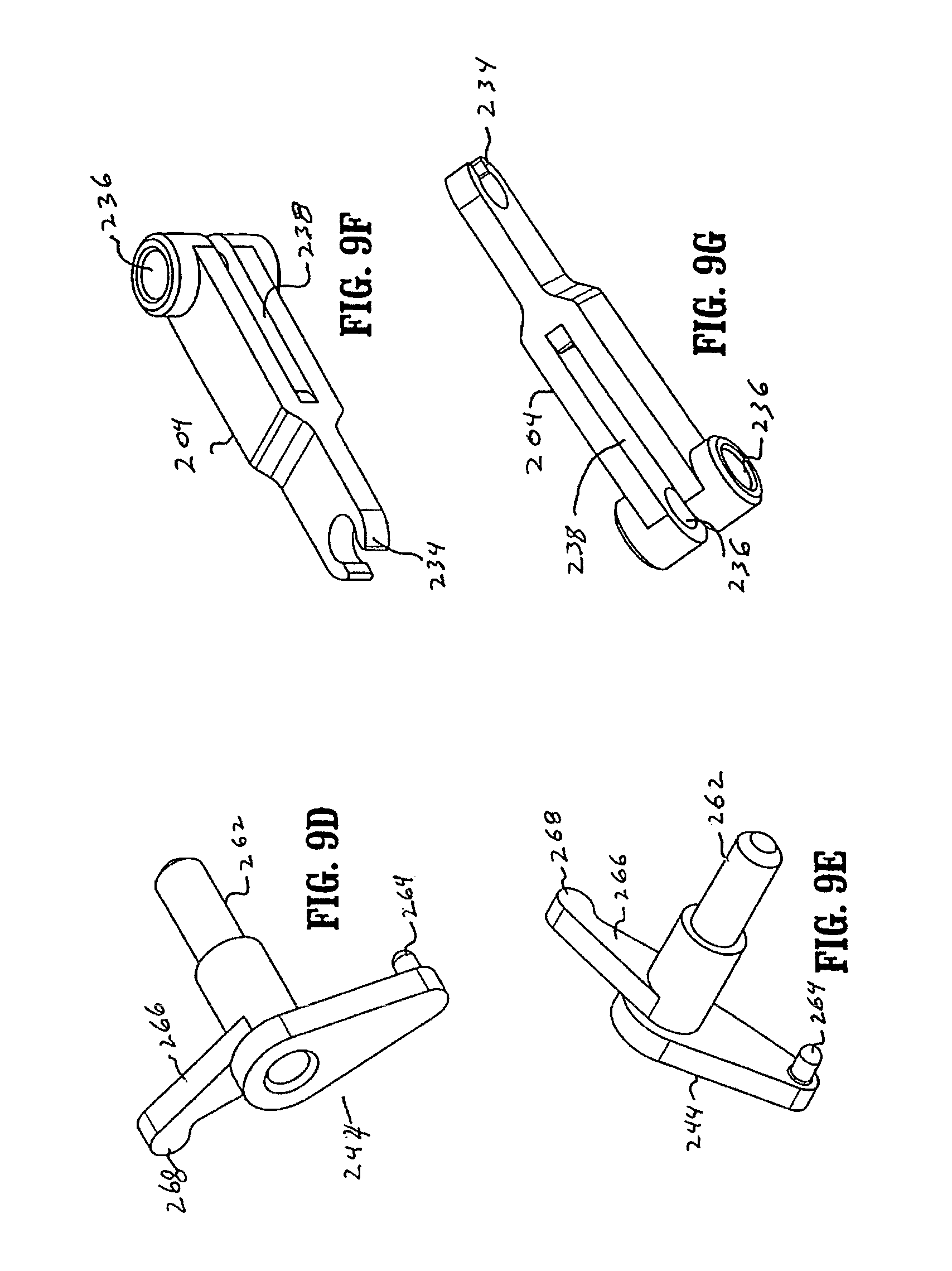
D00013

D00014

D00015

D00016
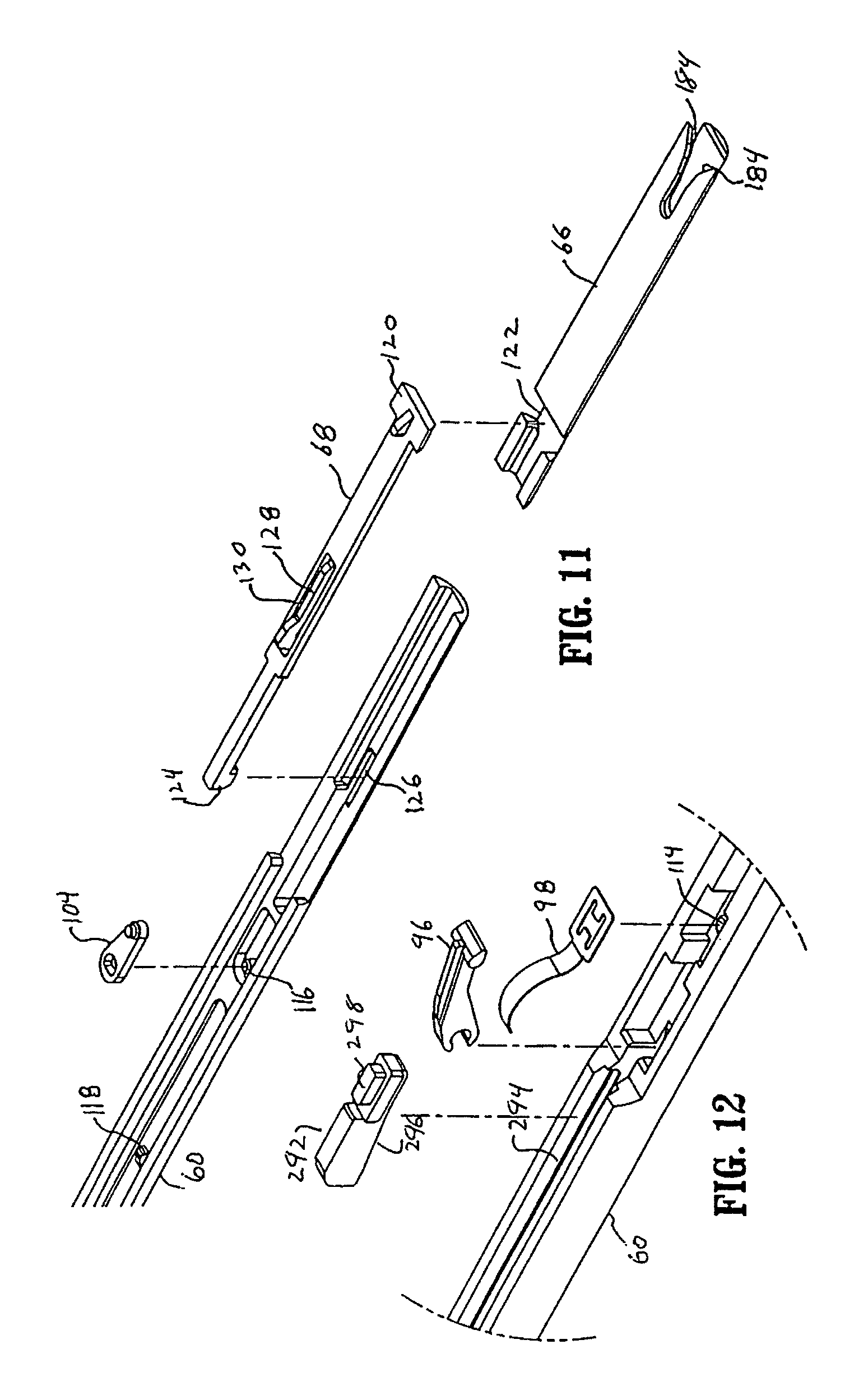
D00017
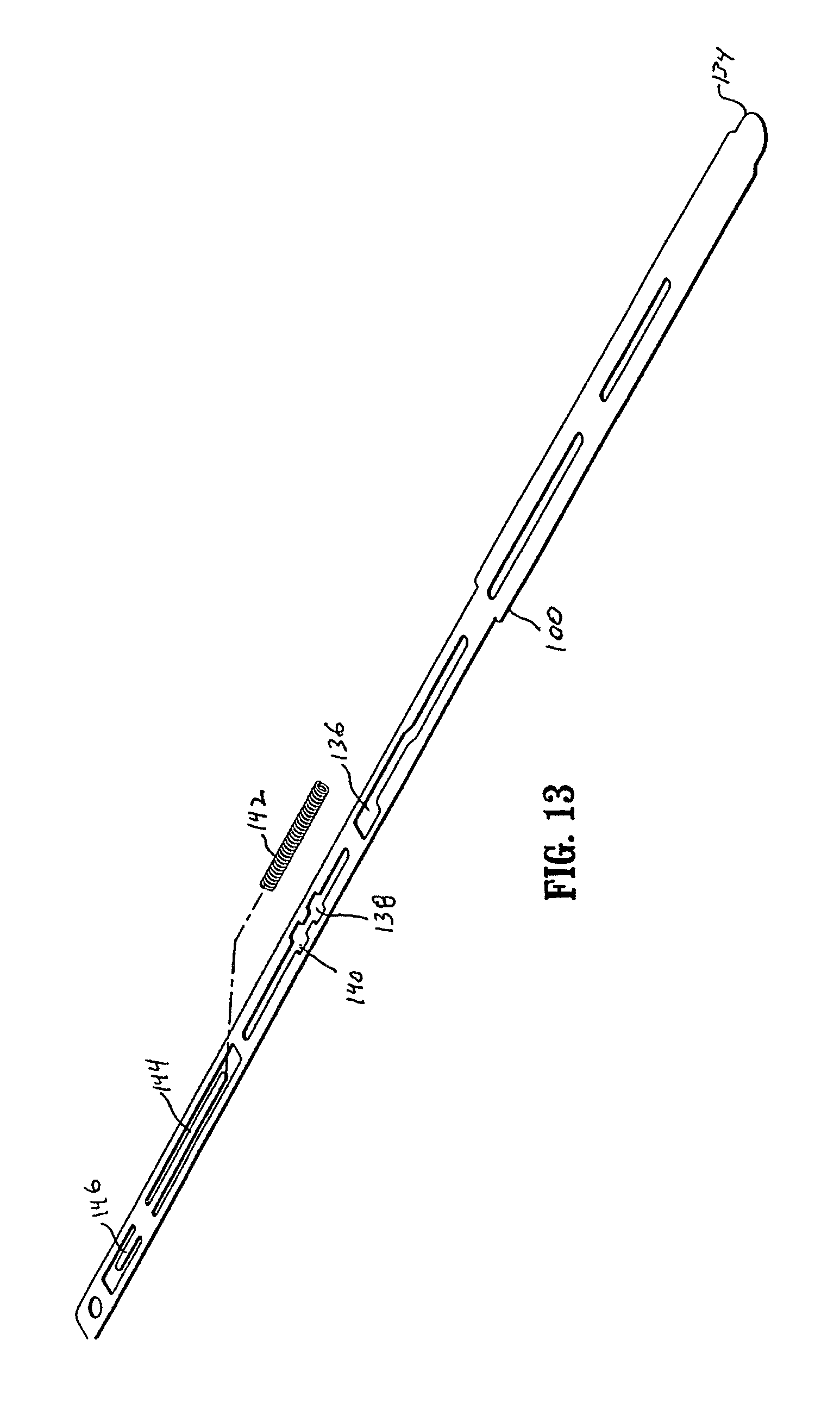
D00018

D00019

D00020

D00021
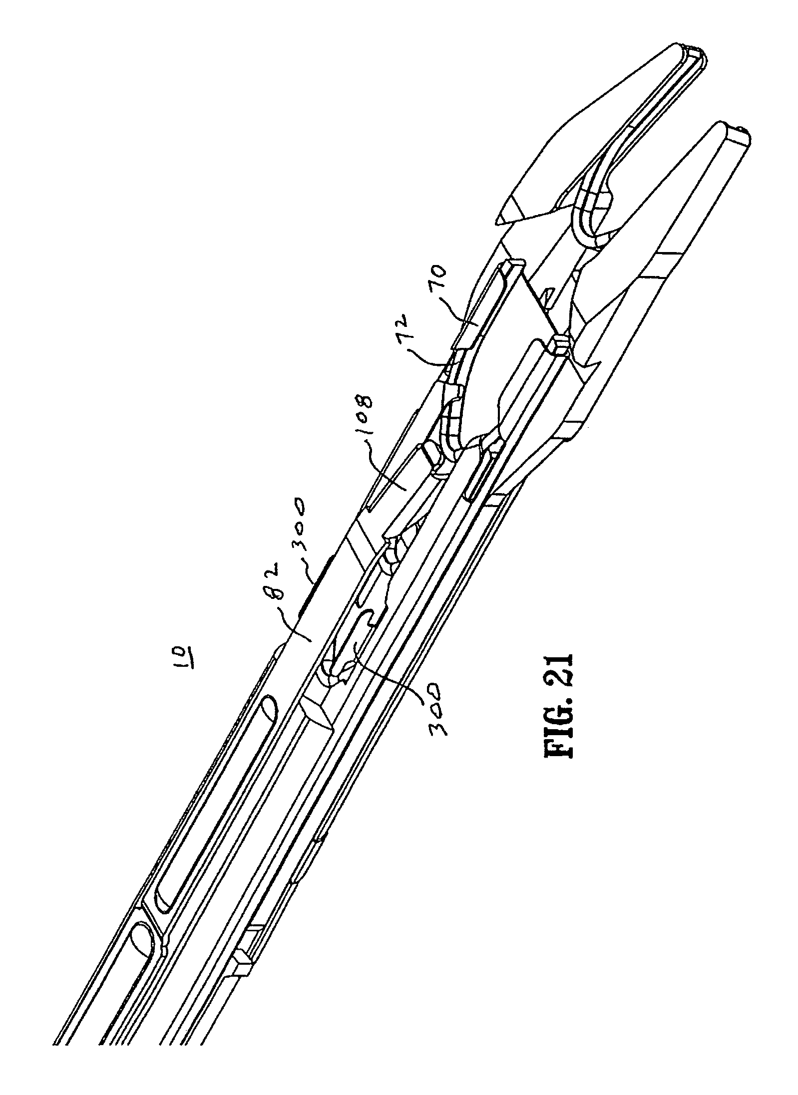
D00022
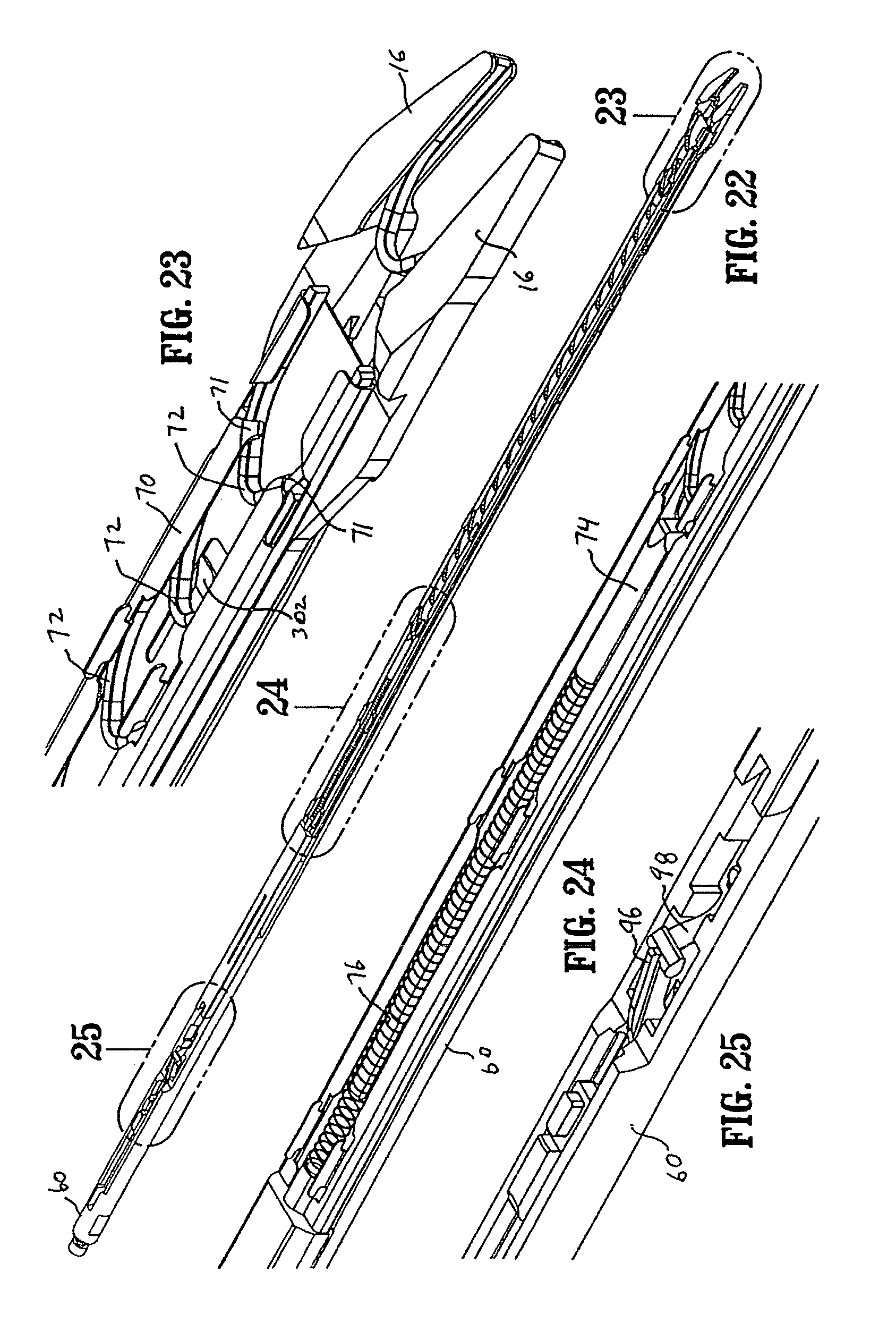
D00023

D00024

D00025

D00026

D00027

D00028

D00029
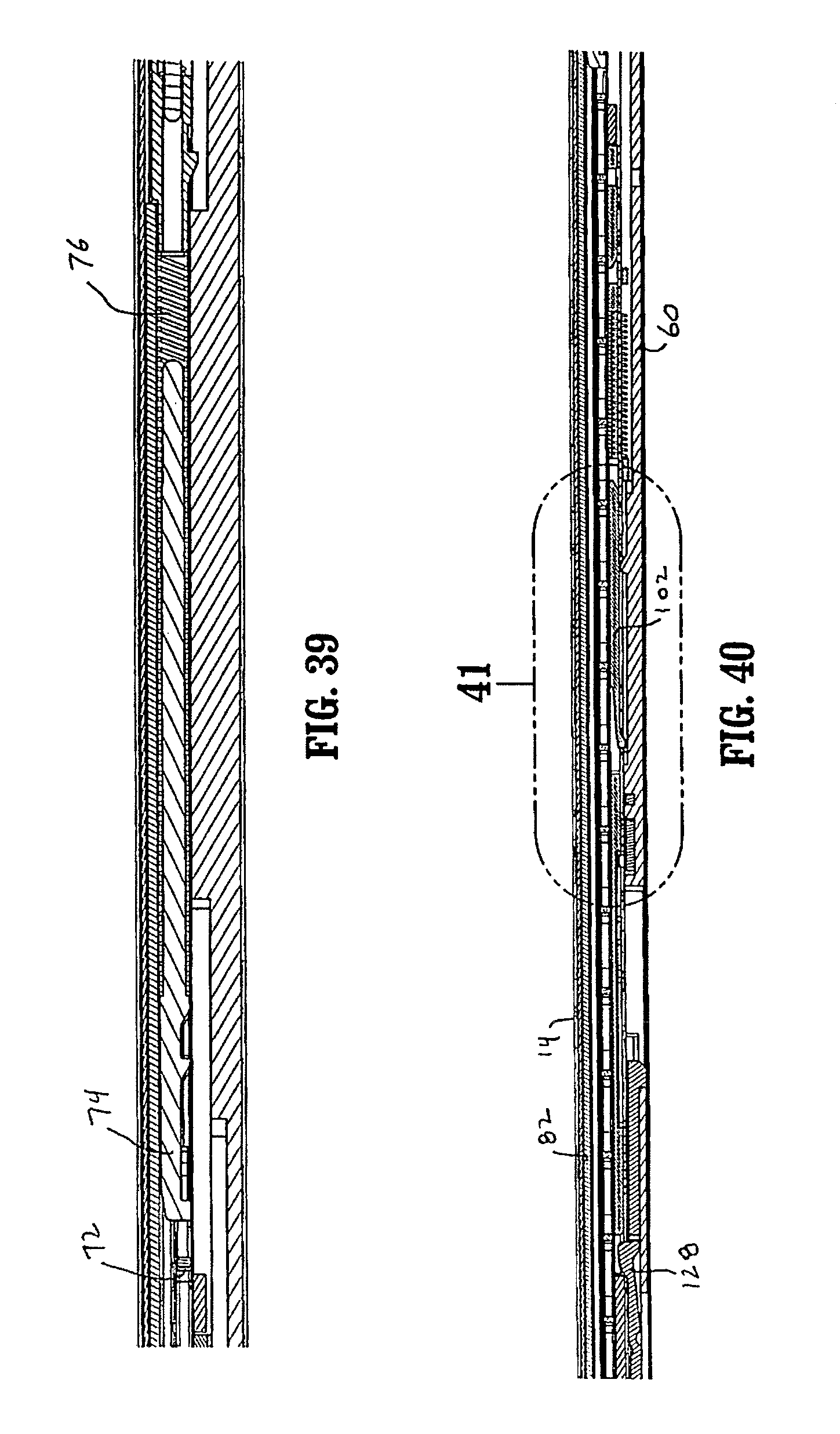
D00030

D00031
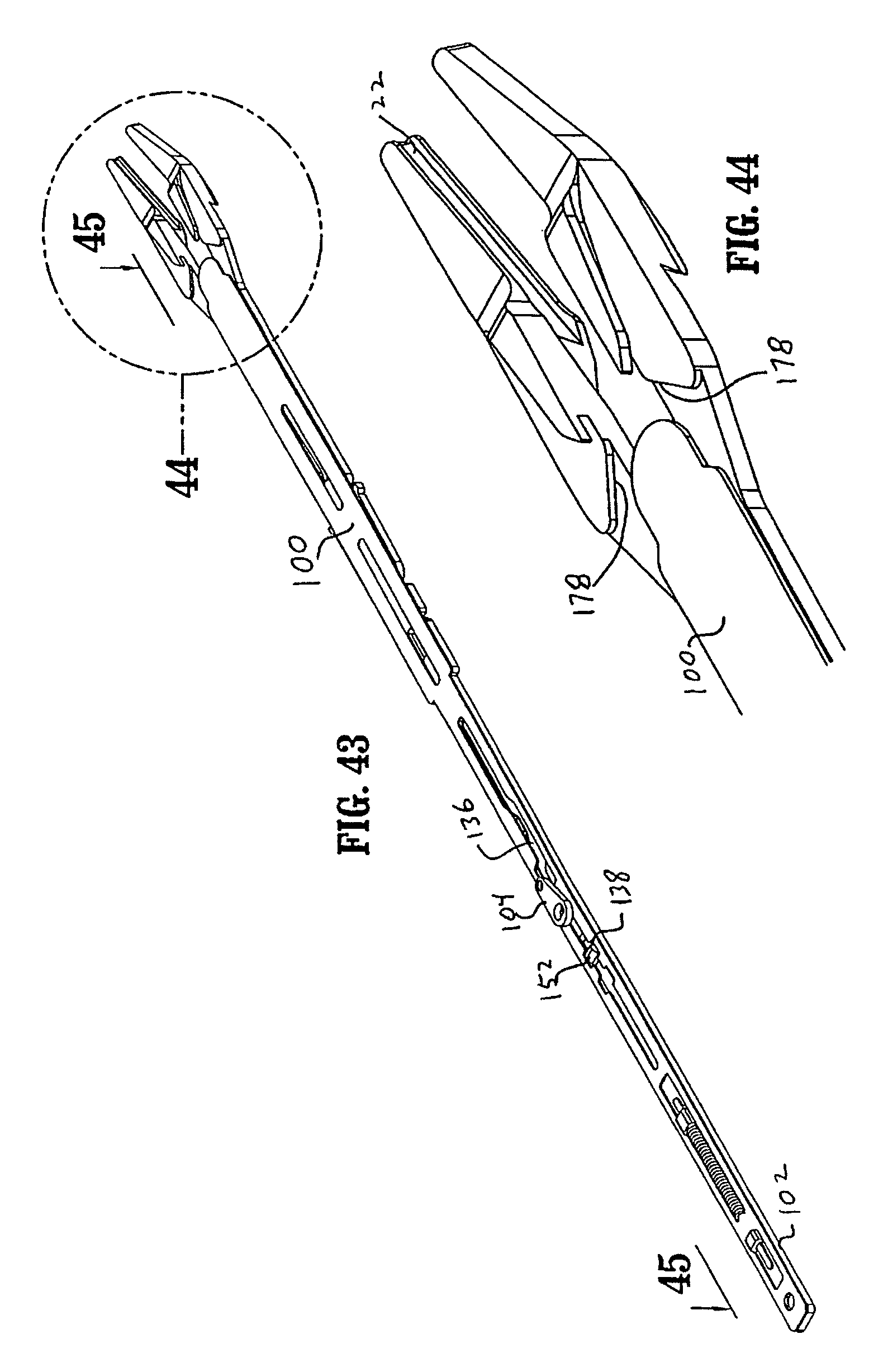
D00032

D00033

D00034
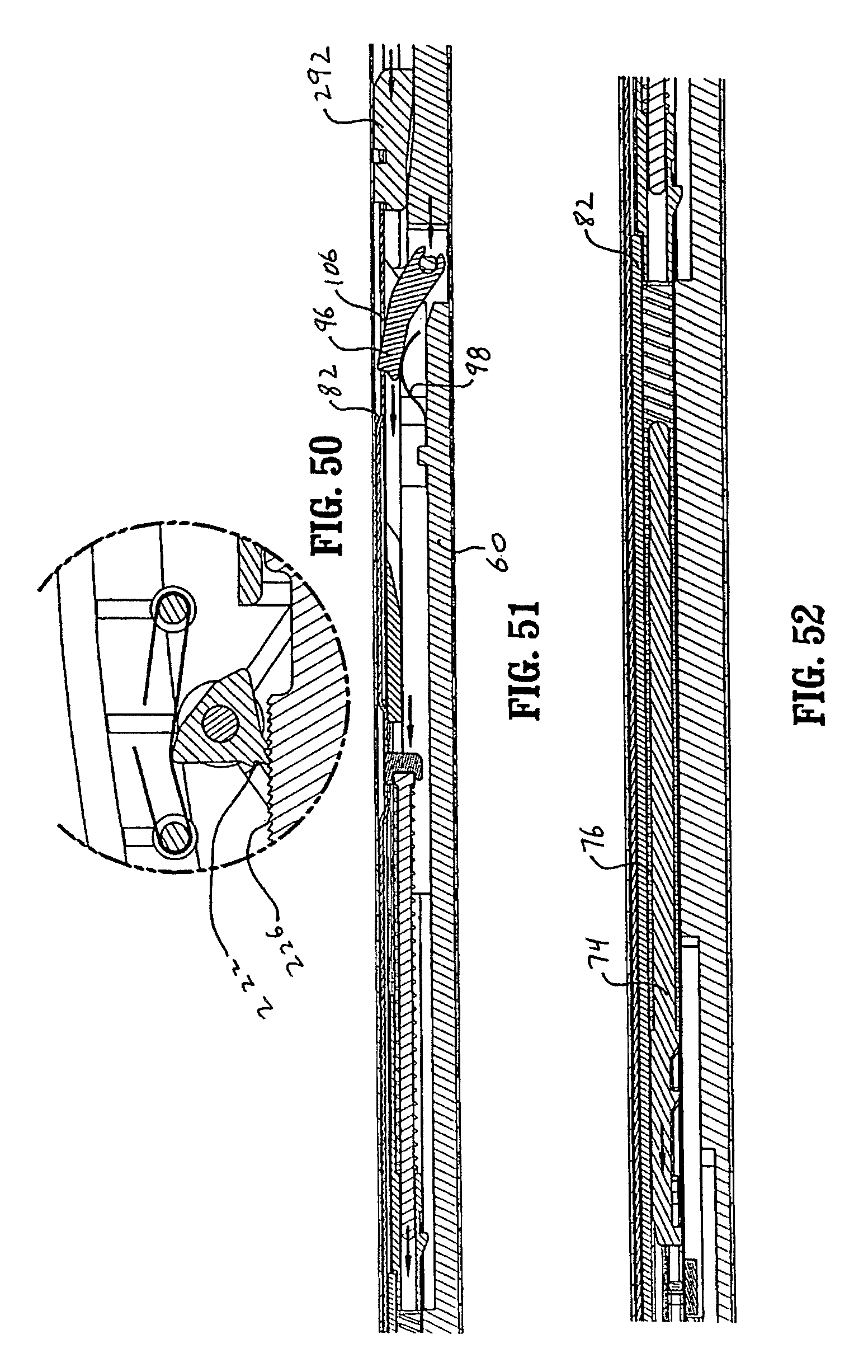
D00035

D00036

D00037

D00038

D00039
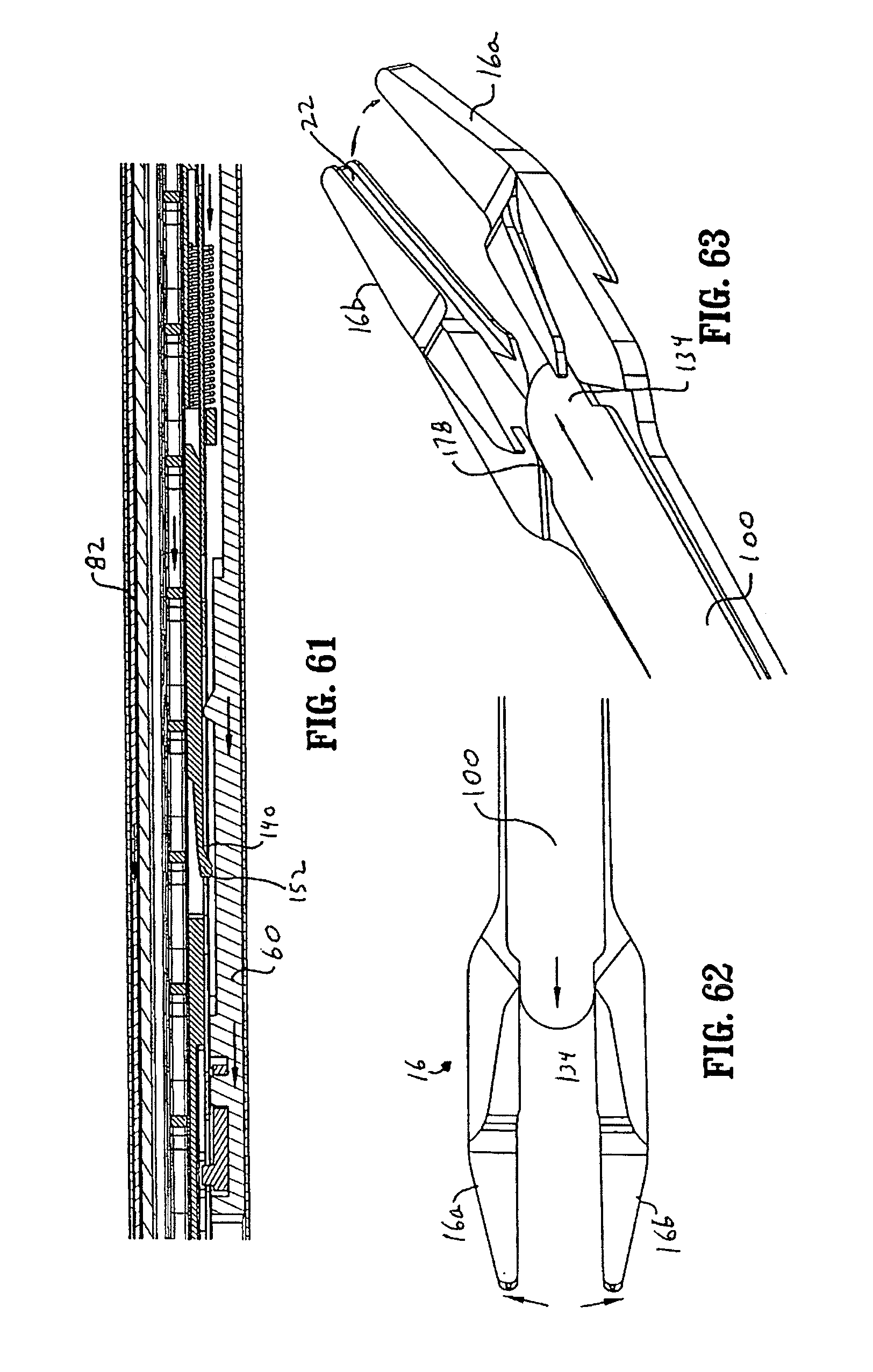
D00040
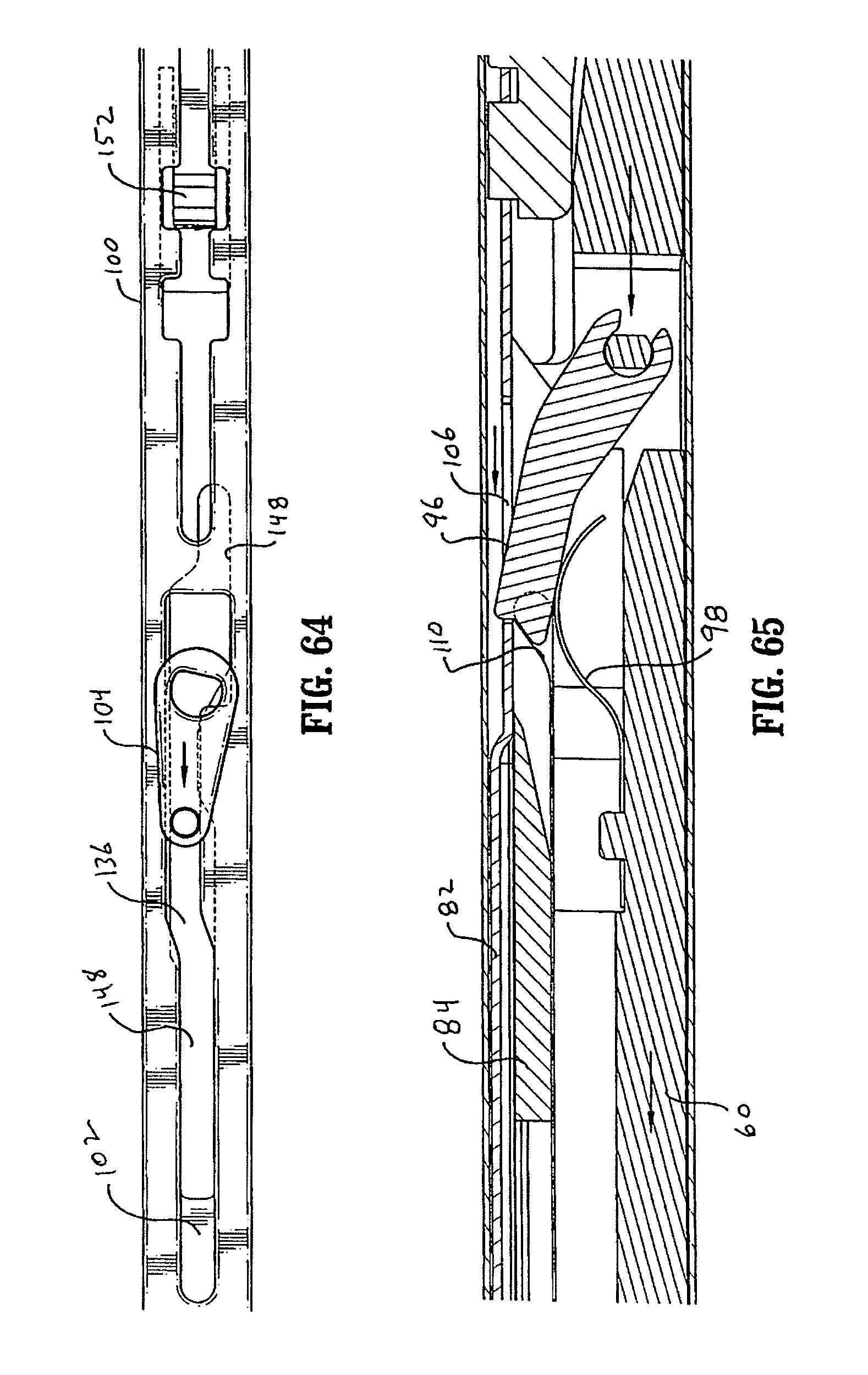
D00041

D00042
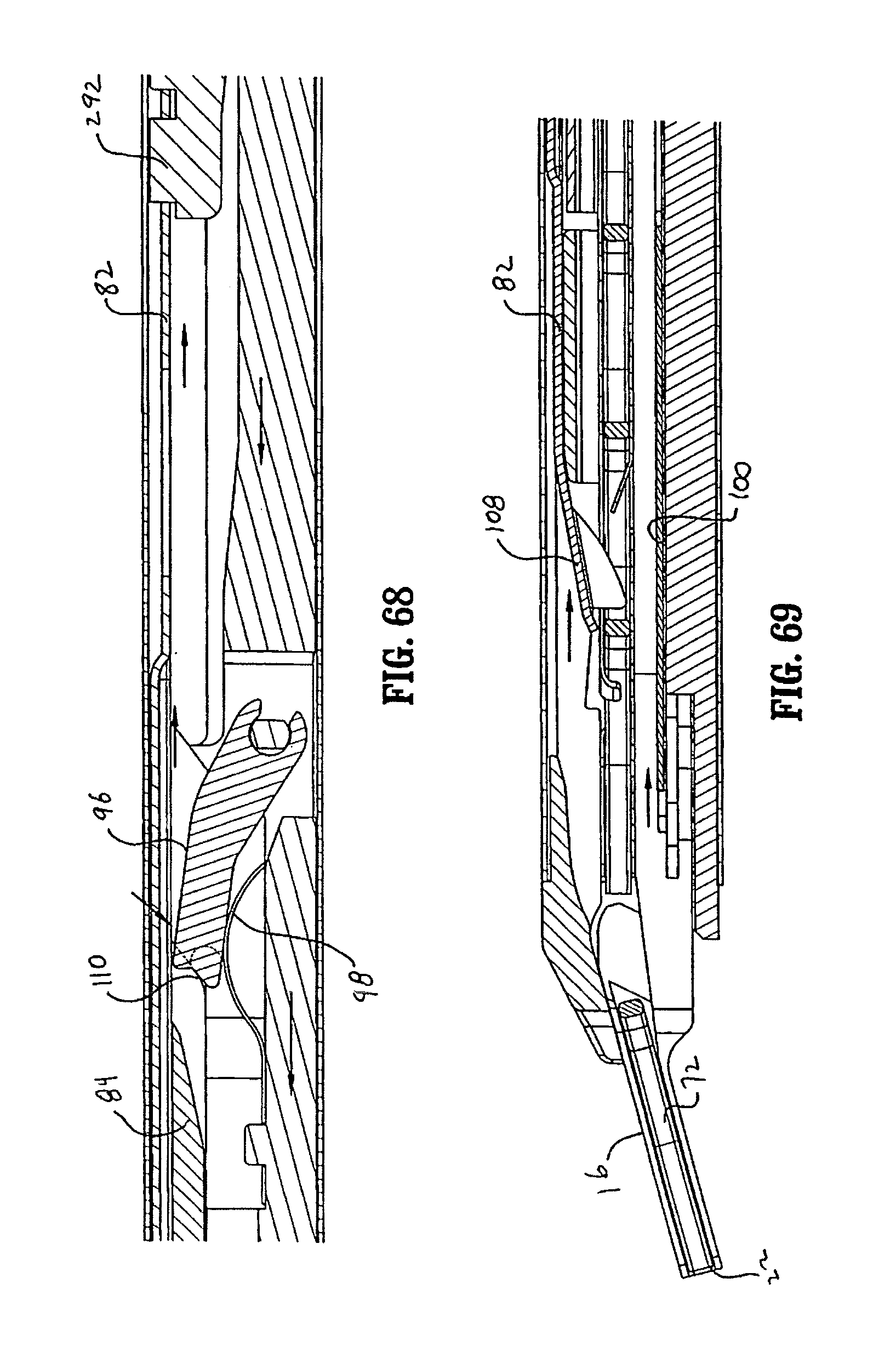
D00043

D00044

D00045
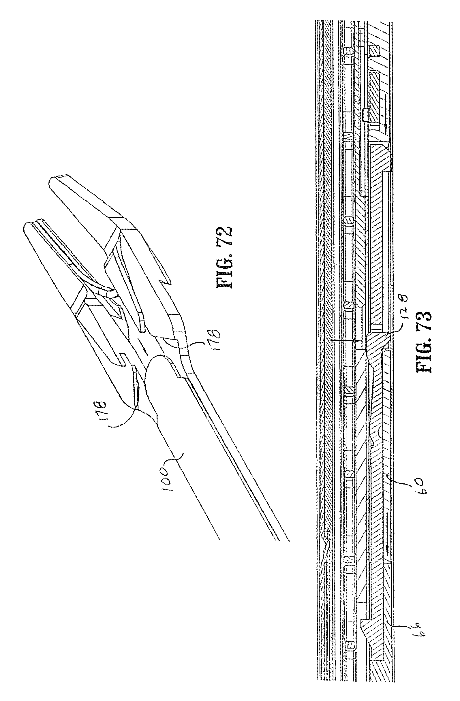
D00046

D00047

D00048

D00049
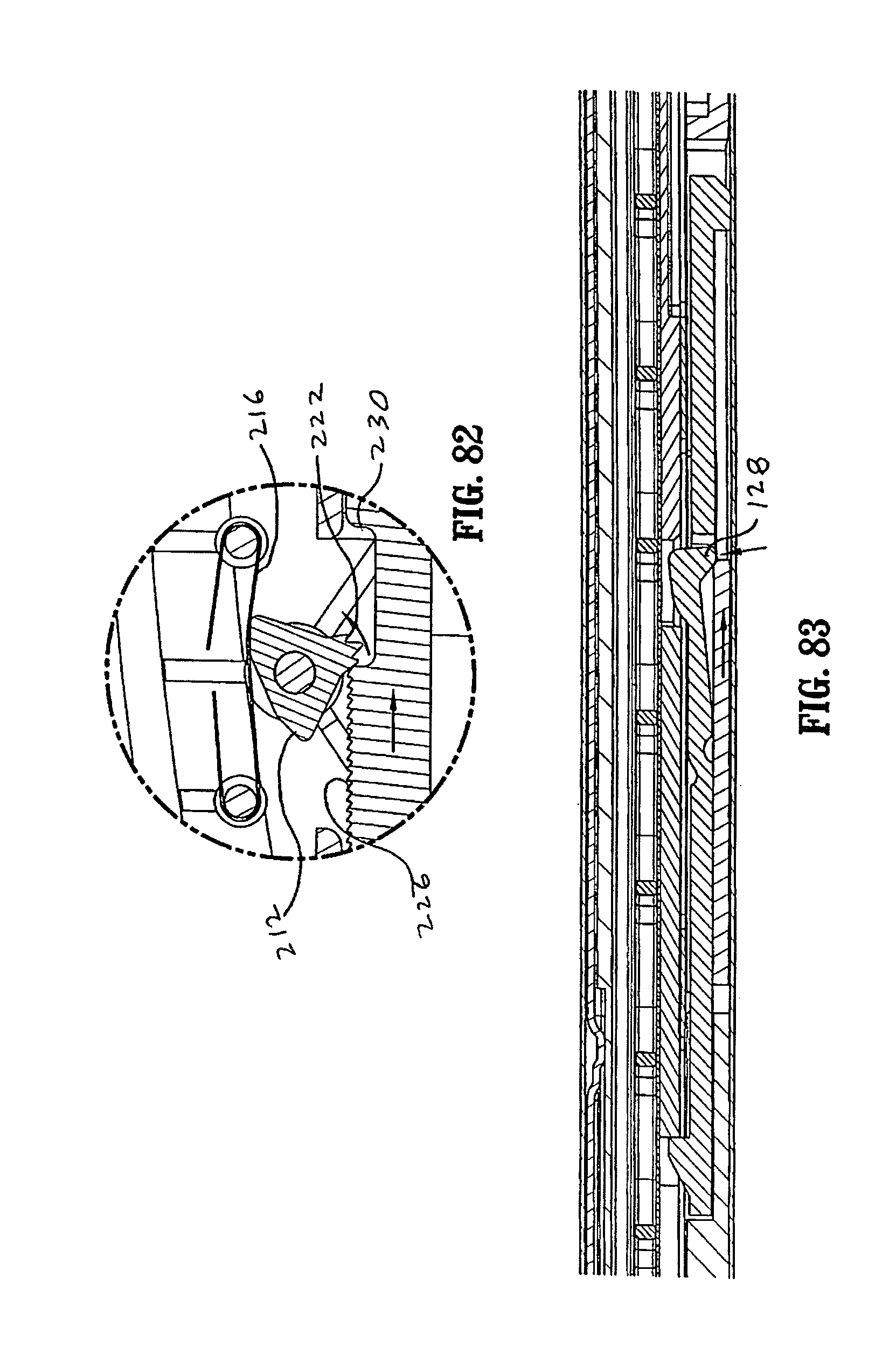
D00050
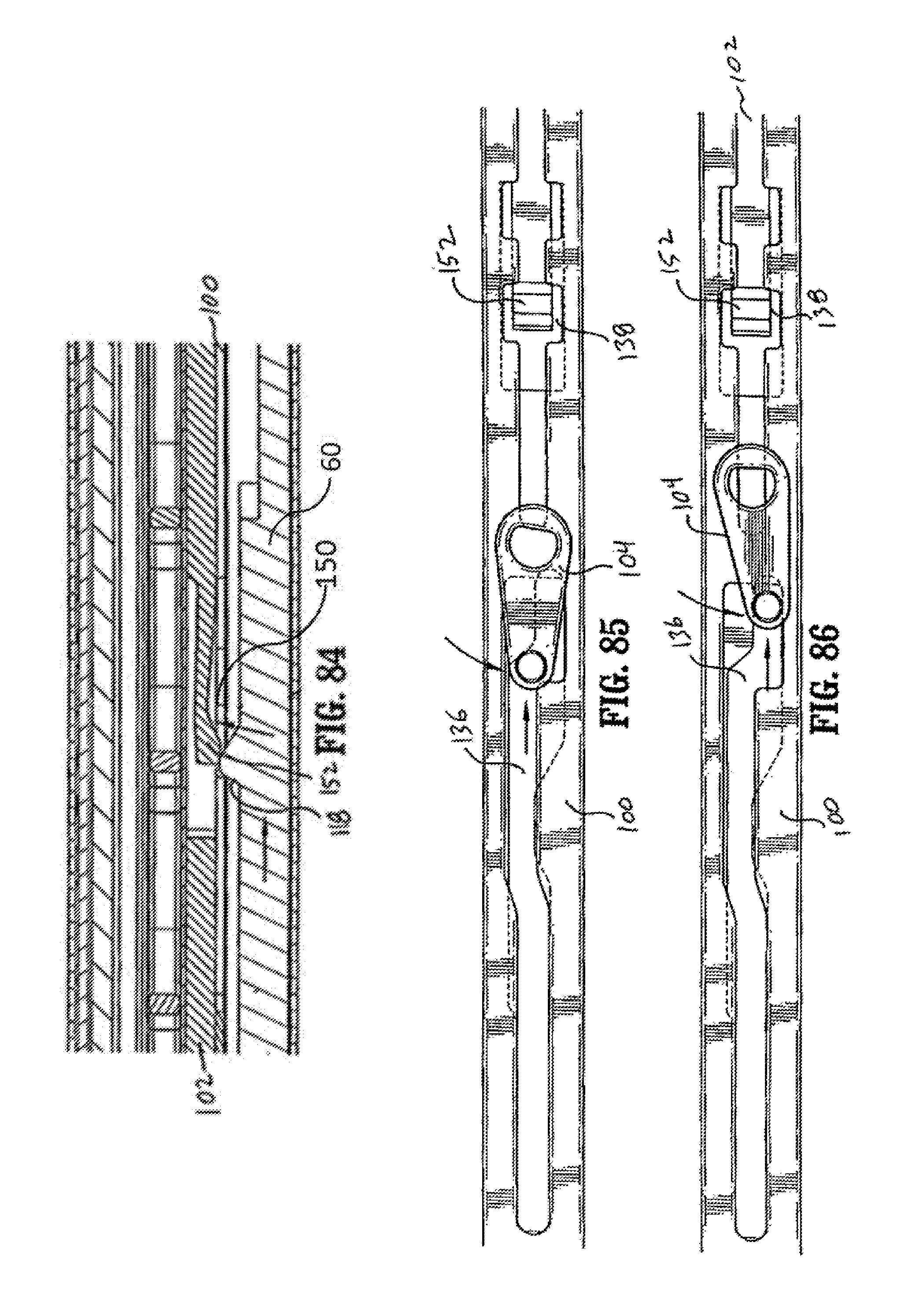
D00051
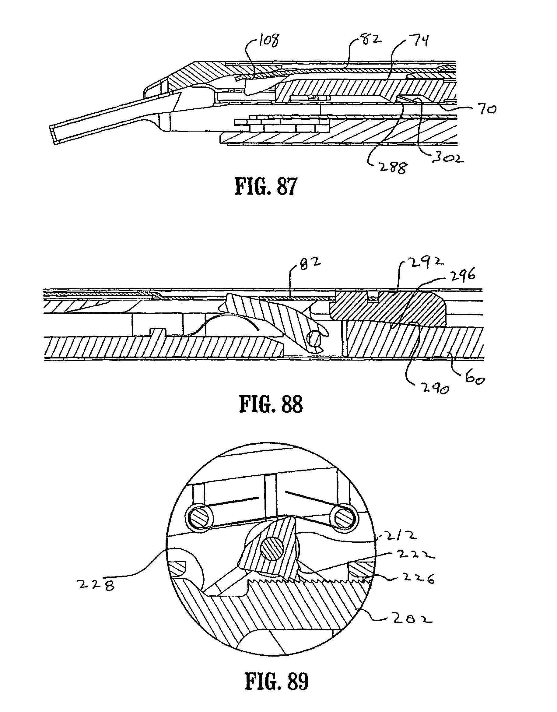
XML
uspto.report is an independent third-party trademark research tool that is not affiliated, endorsed, or sponsored by the United States Patent and Trademark Office (USPTO) or any other governmental organization. The information provided by uspto.report is based on publicly available data at the time of writing and is intended for informational purposes only.
While we strive to provide accurate and up-to-date information, we do not guarantee the accuracy, completeness, reliability, or suitability of the information displayed on this site. The use of this site is at your own risk. Any reliance you place on such information is therefore strictly at your own risk.
All official trademark data, including owner information, should be verified by visiting the official USPTO website at www.uspto.gov. This site is not intended to replace professional legal advice and should not be used as a substitute for consulting with a legal professional who is knowledgeable about trademark law.