Intraoral appliance for sound transmission via bone conduction
Abolfathi Nov
U.S. patent number 10,484,805 [Application Number 15/896,915] was granted by the patent office on 2019-11-19 for intraoral appliance for sound transmission via bone conduction. This patent grant is currently assigned to SoundMed, LLC. The grantee listed for this patent is SoundMed, LLC. Invention is credited to Amir A. Abolfathi.


| United States Patent | 10,484,805 |
| Abolfathi | November 19, 2019 |
Intraoral appliance for sound transmission via bone conduction
Abstract
An intra-oral appliance for transmitting sound via bone conduction and optimized for comfort, safety, speech intelligibility, eating and drinking and extended wear by the user including an actuator to provide bone conduction sound transmission; a transceiver coupled to the actuator to cause the actuator to generate sound; and a first chamber containing the actuator and the transceiver, said first chamber adapted to be coupled to one or more teeth of the user.
| Inventors: | Abolfathi; Amir A. (Petaluma, CA) | ||||||||||
|---|---|---|---|---|---|---|---|---|---|---|---|
| Applicant: |
|
||||||||||
| Assignee: | SoundMed, LLC (Mountain View,
CA) |
||||||||||
| Family ID: | 43243411 | ||||||||||
| Appl. No.: | 15/896,915 | ||||||||||
| Filed: | February 14, 2018 |
Prior Publication Data
| Document Identifier | Publication Date | |
|---|---|---|
| US 20180176701 A1 | Jun 21, 2018 | |
Related U.S. Patent Documents
| Application Number | Filing Date | Patent Number | Issue Date | ||
|---|---|---|---|---|---|
| 15607114 | May 26, 2017 | 9900714 | |||
| 15209570 | Oct 3, 2017 | 9781525 | |||
| 13872965 | Jan 19, 2016 | 9398370 | |||
| 12878276 | Apr 30, 2013 | 8433082 | |||
| 61248262 | Oct 2, 2009 | ||||
| Current U.S. Class: | 1/1 |
| Current CPC Class: | H04R 25/606 (20130101); H04R 25/554 (20130101); H04R 17/005 (20130101); B33Y 80/00 (20141201); H04R 1/46 (20130101); H04R 2460/13 (20130101) |
| Current International Class: | H04R 25/00 (20060101); B33Y 80/00 (20150101); H04R 1/46 (20060101); H04R 17/00 (20060101) |
References Cited [Referenced By]
U.S. Patent Documents
| 2045404 | June 1936 | Nicholides |
| 2161169 | June 1939 | Jefferis |
| 2230397 | February 1941 | Abraham |
| 2239550 | April 1941 | Cubert |
| 2242118 | May 1941 | Fischer |
| 2318872 | May 1943 | Madiera |
| 2848811 | August 1958 | Wagner |
| 2908974 | October 1959 | Stifter |
| 2977425 | March 1961 | Cole |
| 2995633 | August 1961 | Puharich et al. |
| 3156787 | November 1964 | Puharich et al. |
| 3170993 | February 1965 | Puharich et al. |
| 3267931 | August 1966 | Puharich et al. |
| 3325743 | June 1967 | Blum |
| 3712962 | January 1973 | Epley |
| 3787641 | January 1974 | Santori |
| 3894196 | July 1975 | Briskey |
| 3985977 | October 1976 | Beaty et al. |
| 4025732 | May 1977 | Traunmuller |
| 4133975 | January 1979 | Barker, III |
| 4150262 | April 1979 | Ono |
| 4382780 | May 1983 | Kurz |
| 4443668 | April 1984 | Warren |
| 4478224 | October 1984 | Bailey |
| 4498461 | February 1985 | Hakansson |
| 4511330 | April 1985 | Smiley et al. |
| 4591668 | May 1986 | Iwata |
| 4612915 | September 1986 | Hough et al. |
| 4629424 | December 1986 | Lauks et al. |
| 4642769 | February 1987 | Petrofsky |
| 4729366 | March 1988 | Schaefer |
| 4738268 | April 1988 | Kipnis |
| 4791673 | December 1988 | Schreiber |
| 4817044 | March 1989 | Ogren |
| 4827525 | May 1989 | Hotvet et al. |
| 4832033 | May 1989 | Maher et al. |
| 4867682 | September 1989 | Hammesfahr et al. |
| 4904233 | February 1990 | Haakansson et al. |
| 4920984 | May 1990 | Furumichi et al. |
| 4962559 | October 1990 | Schuman |
| 4977623 | December 1990 | Demarco |
| 4982434 | January 1991 | Lenhardt et al. |
| 5012520 | April 1991 | Steeger |
| 5026278 | June 1991 | Oxman et al. |
| 5033999 | July 1991 | Mersky |
| 5047994 | September 1991 | Lenhardt et al. |
| 5060526 | October 1991 | Barth et al. |
| 5082007 | January 1992 | Adell |
| 5165131 | November 1992 | Staar |
| 5194003 | March 1993 | Garay |
| 5212476 | May 1993 | Maloney |
| 5233987 | August 1993 | Fabian et al. |
| 5277694 | January 1994 | Leysieffer et al. |
| 5323468 | June 1994 | Bottesch |
| 5325436 | June 1994 | Soli et al. |
| 5326349 | July 1994 | Baraff |
| 5354326 | October 1994 | Comben et al. |
| 5372142 | December 1994 | Madsen et al. |
| 5402496 | March 1995 | Soli et al. |
| 5403262 | April 1995 | Gooch |
| 5447489 | September 1995 | Issalene |
| 5455842 | October 1995 | Merskey et al. |
| 5460593 | October 1995 | Mersky et al. |
| 5477489 | December 1995 | Wiedmann |
| 5485851 | January 1996 | Erickson |
| 5487012 | January 1996 | Topholm et al. |
| 5506095 | April 1996 | Callne |
| 5523745 | June 1996 | Fortune et al. |
| 5546459 | August 1996 | Sih et al. |
| 5558618 | September 1996 | Maniglia |
| 5565759 | October 1996 | Dunstan |
| 5579284 | November 1996 | May |
| 5586562 | December 1996 | Matz |
| 5616027 | April 1997 | Jacobs et al. |
| 5624376 | April 1997 | Ball et al. |
| 5659156 | August 1997 | Mauney et al. |
| 5661813 | August 1997 | Shimauchi et al. |
| 5668883 | September 1997 | Abe et al. |
| 5673328 | September 1997 | Wandl et al. |
| 5680028 | October 1997 | McEachern |
| 5701348 | December 1997 | Shennib et al. |
| 5706251 | January 1998 | May |
| 5730151 | March 1998 | Summer et al. |
| 5735790 | April 1998 | Hakansson et al. |
| 5760692 | June 1998 | Block |
| 5772575 | June 1998 | Lesinski et al. |
| 5788656 | August 1998 | Mino |
| 5793875 | August 1998 | Lehr et al. |
| 5795287 | August 1998 | Ball et al. |
| 5800336 | September 1998 | Ball et al. |
| 5812496 | September 1998 | Peck |
| 5828765 | October 1998 | Gable |
| 5844996 | December 1998 | Enzmann et al. |
| 5864481 | January 1999 | Gross et al. |
| 5889871 | March 1999 | Downs, Jr. |
| 5899847 | May 1999 | Adams et al. |
| 5902167 | May 1999 | Filo et al. |
| 5914701 | June 1999 | Gersheneld et al. |
| 5930202 | July 1999 | Duckworth et al. |
| 5961443 | October 1999 | Rastatter et al. |
| 5980246 | November 1999 | Ramsay et al. |
| 5984681 | November 1999 | Huang |
| 6029558 | February 2000 | Stevens et al. |
| 6047074 | April 2000 | Zoels et al. |
| 6057668 | May 2000 | Chao |
| 6068589 | May 2000 | Neukermans |
| 6068590 | May 2000 | Brisken |
| 6072884 | June 2000 | Kates |
| 6072885 | June 2000 | Stockham, Jr. et al. |
| 6075557 | June 2000 | Holliman et al. |
| 6086662 | July 2000 | Brodkin et al. |
| 6089864 | July 2000 | Buckner et al. |
| 6115477 | September 2000 | Filo et al. |
| 6116983 | September 2000 | Long et al. |
| 6118882 | September 2000 | Haynes |
| 6171229 | January 2001 | Kroll et al. |
| 6174278 | January 2001 | Jaeger et al. |
| 6184651 | February 2001 | Fernandez et al. |
| 6200133 | March 2001 | Kittelsen |
| 6223018 | April 2001 | Fukumoto et al. |
| 6239705 | May 2001 | Glen |
| 6261237 | July 2001 | Swanson et al. |
| 6333269 | December 2001 | Naito et al. |
| 6371758 | April 2002 | Kittelsen |
| 6377693 | April 2002 | Lippa et al. |
| 6390971 | May 2002 | Adams et al. |
| 6394969 | May 2002 | Lenhardt |
| 6447294 | September 2002 | Price |
| 6504942 | January 2003 | Hong et al. |
| 6516228 | February 2003 | Berrang et al. |
| 6533747 | March 2003 | Polaschegg et al. |
| 6538558 | March 2003 | Sakazume et al. |
| 6551761 | April 2003 | Hall-Goulle et al. |
| 6554761 | April 2003 | Puria et al. |
| 6585637 | July 2003 | Brillhart et al. |
| 6613001 | September 2003 | Dworkin |
| 6626822 | September 2003 | Jaeger et al. |
| 6629922 | October 2003 | Puria et al. |
| 6631197 | October 2003 | Taenzer |
| 6633747 | October 2003 | Reiss |
| 6658124 | December 2003 | Meadows |
| 6682472 | January 2004 | Davis |
| 6694035 | February 2004 | Teicher et al. |
| 6754472 | June 2004 | Williams et al. |
| 6756901 | June 2004 | Campman |
| 6778674 | August 2004 | Panasik et al. |
| 6826284 | November 2004 | Benesty et al. |
| 6849536 | February 2005 | Lee et al. |
| 6885753 | April 2005 | Bank |
| 6917688 | July 2005 | Yu et al. |
| 6937736 | August 2005 | Toda |
| 6937769 | August 2005 | Onno |
| 6941952 | September 2005 | Rush, III |
| 6954668 | October 2005 | Cuozzo |
| 6985599 | January 2006 | Asnes |
| 7003099 | February 2006 | Zhang et al. |
| 7010139 | March 2006 | Smeehuyzen |
| 7033313 | April 2006 | Lupin et al. |
| 7035415 | April 2006 | Belt et al. |
| 7065223 | June 2006 | Westerkull |
| 7074222 | July 2006 | Westerkull |
| 7076077 | July 2006 | Atsumi et al. |
| 7099822 | August 2006 | Zangi |
| 7162420 | January 2007 | Zangi et al. |
| 7164948 | January 2007 | Struble et al. |
| 7171003 | January 2007 | Venkatesh et al. |
| 7171008 | January 2007 | Elko |
| 7174022 | February 2007 | Zhang et al. |
| 7174026 | February 2007 | Niederdrank |
| 7190995 | March 2007 | Chervin et al. |
| 7198596 | April 2007 | Westerkull |
| 7206423 | April 2007 | Feng et al. |
| 7246058 | July 2007 | Burnett |
| 7246619 | July 2007 | Truschel et al. |
| 7258533 | August 2007 | Tanner et al. |
| 7269266 | September 2007 | Anjanappa |
| 7271569 | September 2007 | Oglesbee |
| 7281924 | October 2007 | Ellison |
| 7298857 | November 2007 | Shennib et al. |
| 7310427 | December 2007 | Retchin et al. |
| 7329226 | February 2008 | Ni et al. |
| 7331349 | February 2008 | Brady et al. |
| 7333624 | February 2008 | Husung |
| 7361216 | April 2008 | Kangas et al. |
| 7409070 | August 2008 | Pitulia |
| 7433484 | October 2008 | Asseily et al. |
| 7436974 | October 2008 | Harper |
| 7463929 | December 2008 | Simmons |
| 7486798 | February 2009 | Anjanappa et al. |
| 7512448 | March 2009 | Malick et al. |
| 7512720 | March 2009 | Schultz et al. |
| 7520851 | April 2009 | Davis et al. |
| 7522738 | April 2009 | Miller, III |
| 7522740 | April 2009 | Julstrom et al. |
| 7610919 | November 2009 | Utley et al. |
| 7629897 | December 2009 | Koljonen |
| 7664277 | February 2010 | Abolfathi et al. |
| 7680284 | March 2010 | Lee et al. |
| 7682303 | March 2010 | Abolfathi |
| 7724911 | May 2010 | Menzel et al. |
| 7787946 | August 2010 | Stahmann et al. |
| 7796769 | September 2010 | Abolfathi |
| 7801319 | September 2010 | Abolfathi |
| 7806831 | October 2010 | Lavie et al. |
| 7844064 | November 2010 | Abolfathi et al. |
| 7844070 | November 2010 | Abolfathi |
| 7845041 | December 2010 | Gatzemeyer et al. |
| 7853030 | December 2010 | Grasbon et al. |
| 7854698 | December 2010 | Abolfathi |
| 7876906 | January 2011 | Abolfathi |
| 7945068 | May 2011 | Abolfathi et al. |
| 7974845 | July 2011 | Spiridigliozzi et al. |
| 8023676 | September 2011 | Abolfathi et al. |
| 8043091 | October 2011 | Schmitt |
| 8150075 | April 2012 | Abolfathi et al. |
| 8160279 | April 2012 | Abolfathi |
| 8170242 | May 2012 | Menzel et al. |
| 8177705 | May 2012 | Abolfathi |
| 8189838 | May 2012 | Rich |
| 8189840 | May 2012 | Guenther |
| 8224013 | July 2012 | Abolfathi et al. |
| 8233654 | July 2012 | Abolfathi |
| 8254611 | August 2012 | Abolfathi et al. |
| 8270637 | September 2012 | Abolfathi |
| 8270638 | September 2012 | Abolfathi et al. |
| 8291912 | October 2012 | Abolfathi et al. |
| 8295506 | October 2012 | Kassayan et al. |
| 8333203 | December 2012 | Spiridigliozzi et al. |
| 8358792 | January 2013 | Menzel et al. |
| 8433080 | April 2013 | Rader et al. |
| 8433082 | April 2013 | Abolfathi |
| 8433083 | April 2013 | Abolfathi et al. |
| 8503930 | August 2013 | Kassayan |
| 8577066 | November 2013 | Abolfathi |
| 8585575 | November 2013 | Abolfathi |
| 8588447 | November 2013 | Abolfathi et al. |
| 8649535 | February 2014 | Menzel et al. |
| 8649536 | February 2014 | Kassayan et al. |
| 8649543 | February 2014 | Abolfathi et al. |
| 8660278 | February 2014 | Abolfathi et al. |
| 8712077 | April 2014 | Abolfathi |
| 8712078 | April 2014 | Abolfathi |
| 8795172 | August 2014 | Abolfathi et al. |
| 8867994 | October 2014 | Kassayan et al. |
| 9049527 | June 2015 | Andersson et al. |
| 9113262 | August 2015 | Abolfathi et al. |
| 9143873 | September 2015 | Abolfathi |
| 9185485 | November 2015 | Abolfathi |
| 9247332 | January 2016 | Kassayan et al. |
| 9398370 | July 2016 | Abolfathi |
| 9615182 | April 2017 | Abolfathi et al. |
| 9736602 | August 2017 | Menzel et al. |
| 9781525 | October 2017 | Abolfathi |
| 9781526 | October 2017 | Abolfathi |
| 9826324 | November 2017 | Abolfathi |
| 9900714 | February 2018 | Abolfathi |
| 9906878 | February 2018 | Abolfathi et al. |
| 10109289 | October 2018 | Kassayan et al. |
| 10194255 | January 2019 | Menzel et al. |
| 2001/0003788 | June 2001 | Ball et al. |
| 2001/0033669 | October 2001 | Bank et al. |
| 2001/0051776 | December 2001 | Lenhardt |
| 2002/0026091 | February 2002 | Leysieffer |
| 2002/0039427 | April 2002 | Whitwell et al. |
| 2002/0049479 | April 2002 | Pitts |
| 2002/0071581 | June 2002 | Leysieffer et al. |
| 2002/0077831 | June 2002 | Numa |
| 2002/0122563 | September 2002 | Schumaier |
| 2002/0173697 | November 2002 | Lenhardt |
| 2003/0004403 | February 2003 | Drinan et al. |
| 2003/0048915 | March 2003 | Bank |
| 2003/0059078 | March 2003 | Downs et al. |
| 2003/0091200 | May 2003 | Pompei |
| 2003/0114899 | June 2003 | Woods et al. |
| 2003/0199956 | October 2003 | Struble et al. |
| 2003/0212319 | November 2003 | Magill |
| 2004/0006283 | January 2004 | Harrison et al. |
| 2004/0015058 | January 2004 | Bessen et al. |
| 2004/0057591 | March 2004 | Beck et al. |
| 2004/0063073 | April 2004 | Kajimoto et al. |
| 2004/0127812 | July 2004 | Micheyl et al. |
| 2004/0131200 | July 2004 | Davis |
| 2004/0138723 | July 2004 | Malick et al. |
| 2004/0141624 | July 2004 | Davis et al. |
| 2004/0196998 | October 2004 | Noble |
| 2004/0202339 | October 2004 | O'Brien, Jr. et al. |
| 2004/0202344 | October 2004 | Anjanappa et al. |
| 2004/0214130 | October 2004 | Fischer et al. |
| 2004/0214614 | October 2004 | Aman |
| 2004/0234080 | November 2004 | Hernandez et al. |
| 2004/0243481 | December 2004 | Bradbury et al. |
| 2004/0247143 | December 2004 | Lantrua et al. |
| 2004/0254668 | December 2004 | Jang et al. |
| 2005/0020873 | January 2005 | Berrang et al. |
| 2005/0037312 | February 2005 | Uchida |
| 2005/0067816 | March 2005 | Buckman |
| 2005/0070782 | March 2005 | Brodkin |
| 2005/0088435 | April 2005 | Geng |
| 2005/0090864 | April 2005 | Pines et al. |
| 2005/0113633 | May 2005 | Blau et al. |
| 2005/0115561 | June 2005 | Stathmann et al. |
| 2005/0129257 | June 2005 | Tamura |
| 2005/0137447 | June 2005 | Bernhard |
| 2005/0189910 | September 2005 | Hui |
| 2005/0196008 | September 2005 | Anjanappa et al. |
| 2005/0201574 | September 2005 | Lenhardt |
| 2005/0241646 | November 2005 | Sotos et al. |
| 2005/0271999 | December 2005 | Fishburne |
| 2005/0273170 | December 2005 | Navarro et al. |
| 2006/0008106 | January 2006 | Harper |
| 2006/0025648 | February 2006 | Lupin et al. |
| 2006/0056649 | March 2006 | Schumaier |
| 2006/0064037 | March 2006 | Shalon et al. |
| 2006/0079291 | April 2006 | Granovetter et al. |
| 2006/0155346 | July 2006 | Miller |
| 2006/0166157 | July 2006 | Rahman et al. |
| 2006/0167335 | July 2006 | Park et al. |
| 2006/0207611 | September 2006 | Anonsen |
| 2006/0230108 | October 2006 | Tatsuta et al. |
| 2006/0239468 | October 2006 | Desloge |
| 2006/0253005 | November 2006 | Drinan et al. |
| 2006/0270467 | November 2006 | Song et al. |
| 2006/0275739 | December 2006 | Ray |
| 2006/0277664 | December 2006 | Akhtar |
| 2007/0010704 | January 2007 | Pitulia |
| 2007/0035917 | February 2007 | Hotelling et al. |
| 2007/0036370 | February 2007 | Granovetter et al. |
| 2007/0041595 | February 2007 | Carazo et al. |
| 2007/0050061 | March 2007 | Klein et al. |
| 2007/0093733 | April 2007 | Choy |
| 2007/0105072 | May 2007 | Koljonen |
| 2007/0127755 | June 2007 | Bauman |
| 2007/0142072 | June 2007 | Lassally |
| 2007/0144396 | June 2007 | Hamel et al. |
| 2007/0183613 | August 2007 | Juneau et al. |
| 2007/0208542 | September 2007 | Vock et al. |
| 2007/0223735 | September 2007 | LoPresti et al. |
| 2007/0230713 | October 2007 | Davis |
| 2007/0230736 | October 2007 | Boesen |
| 2007/0239294 | October 2007 | Brueckner et al. |
| 2007/0242835 | October 2007 | Davis |
| 2007/0249889 | October 2007 | Hanson et al. |
| 2007/0258609 | November 2007 | Steinbuss |
| 2007/0265533 | November 2007 | Tran |
| 2007/0276270 | November 2007 | Tran |
| 2007/0280491 | December 2007 | Abolfathi |
| 2007/0280492 | December 2007 | Abolfathi |
| 2007/0280493 | December 2007 | Abolfathi |
| 2007/0280495 | December 2007 | Abolfathi |
| 2007/0286440 | December 2007 | Abolfathi et al. |
| 2007/0291972 | December 2007 | Abolfathi et al. |
| 2008/0019542 | January 2008 | Menzel et al. |
| 2008/0019557 | January 2008 | Bevirt et al. |
| 2008/0021327 | January 2008 | El-Bialy et al. |
| 2008/0045161 | February 2008 | Lee et al. |
| 2008/0064993 | March 2008 | Abolfathi et al. |
| 2008/0070181 | March 2008 | Abolfathi et al. |
| 2008/0109972 | May 2008 | Mah et al. |
| 2008/0144876 | June 2008 | Reining et al. |
| 2008/0146890 | June 2008 | LeBoeuf |
| 2008/0159559 | July 2008 | Akagi et al. |
| 2008/0165996 | July 2008 | Saito et al. |
| 2008/0205678 | August 2008 | Boglayskij et al. |
| 2008/0227047 | September 2008 | Lowe et al. |
| 2008/0304677 | December 2008 | Abolfathi et al. |
| 2009/0014012 | January 2009 | Sanders |
| 2009/0022294 | January 2009 | Goldstein et al. |
| 2009/0022351 | January 2009 | Wieland et al. |
| 2009/0028352 | January 2009 | Petroff |
| 2009/0030529 | January 2009 | Berrang et al. |
| 2009/0043149 | February 2009 | Abel |
| 2009/0052698 | February 2009 | Rader et al. |
| 2009/0052702 | February 2009 | Murphy et al. |
| 2009/0088598 | April 2009 | Abolfathi |
| 2009/0097684 | April 2009 | Abolfathi et al. |
| 2009/0097685 | April 2009 | Menzel et al. |
| 2009/0099408 | April 2009 | Abolfathi et al. |
| 2009/0105523 | April 2009 | Kassayan et al. |
| 2009/0147976 | June 2009 | Abolfathi |
| 2009/0149722 | June 2009 | Abolfathi et al. |
| 2009/0175478 | July 2009 | Nakajima et al. |
| 2009/0180652 | July 2009 | Davis et al. |
| 2009/0208031 | August 2009 | Abolfathi |
| 2009/0210231 | August 2009 | Spiridigliozzi et al. |
| 2009/0220115 | September 2009 | Lantrua |
| 2009/0220921 | September 2009 | Abolfathi et al. |
| 2009/0226011 | September 2009 | Abolfathi et al. |
| 2009/0226017 | September 2009 | Abolfathi et al. |
| 2009/0226020 | September 2009 | Abolfathi |
| 2009/0268932 | October 2009 | Abolfathi et al. |
| 2009/0270032 | October 2009 | Kassayan |
| 2009/0270673 | October 2009 | Abolfathi et al. |
| 2009/0274325 | November 2009 | Abolfathi |
| 2009/0281433 | November 2009 | Saadat et al. |
| 2010/0006111 | January 2010 | Spiridigliozzi et al. |
| 2010/0014689 | January 2010 | Kassayan et al. |
| 2010/0098269 | April 2010 | Abolfathi et al. |
| 2010/0098270 | April 2010 | Abolfathi et al. |
| 2010/0185046 | July 2010 | Abolfathi |
| 2010/0189288 | July 2010 | Menzel et al. |
| 2010/0194333 | August 2010 | Kassayan et al. |
| 2010/0220883 | September 2010 | Menzel et al. |
| 2010/0290647 | November 2010 | Abolfathi et al. |
| 2010/0312568 | December 2010 | Abolfathi |
| 2010/0322449 | December 2010 | Abolfathi |
| 2011/0002492 | January 2011 | Abolfathi et al. |
| 2011/0007920 | January 2011 | Abolfathi et al. |
| 2011/0026740 | February 2011 | Abolfathi |
| 2011/0061647 | March 2011 | Stahmann et al. |
| 2011/0081031 | April 2011 | Abolfathi |
| 2011/0116659 | May 2011 | Abolfathi |
| 2011/0245584 | October 2011 | Abolfathi |
| 2011/0280416 | November 2011 | Abolfathi et al. |
| 2011/0319021 | December 2011 | Proulx et al. |
| 2012/0022389 | January 2012 | Sanders |
| 2012/0116779 | May 2012 | Spiridigliozzi et al. |
| 2012/0142270 | June 2012 | Abolfathi et al. |
| 2012/0165597 | June 2012 | Proulx et al. |
| 2012/0259158 | October 2012 | Abolfathi |
| 2012/0296154 | November 2012 | Abolfathi |
| 2012/0321109 | December 2012 | Abolfathi et al. |
| 2012/0321113 | December 2012 | Abolfathi |
| 2013/0003996 | January 2013 | Menzel et al. |
| 2013/0003997 | January 2013 | Kassayan et al. |
| 2013/0006043 | January 2013 | Abolfathi et al. |
| 2013/0010987 | January 2013 | Abolfathi et al. |
| 2013/0034238 | February 2013 | Abolfathi |
| 2013/0044903 | February 2013 | Abolfathi et al. |
| 2013/0109932 | May 2013 | Saadat et al. |
| 2013/0236035 | September 2013 | Abolfathi |
| 2013/0236043 | September 2013 | Abolfathi et al. |
| 2013/0306230 | November 2013 | Abolfathi et al. |
| 2013/0324043 | December 2013 | Kassayan |
| 2014/0081091 | March 2014 | Abolfathi et al. |
| 2014/0169592 | June 2014 | Menzel et al. |
| 2014/0177879 | June 2014 | Abolfathi et al. |
| 2014/0177880 | June 2014 | Kassayan et al. |
| 2014/0270268 | September 2014 | Abolfathi et al. |
| 2014/0275733 | September 2014 | Abolfathi |
| 2014/0296618 | October 2014 | Abolfalthi |
| 2014/0321667 | October 2014 | Abolfathi |
| 2014/0321674 | October 2014 | Abolfalthi |
| 2014/0349597 | November 2014 | Abolfathi et al. |
| 2015/0358723 | December 2015 | Abolfathi et al. |
| 2016/0134980 | May 2016 | Abolfathi |
| 2016/0217804 | July 2016 | Kassayan et al. |
| 2016/0323679 | November 2016 | Abolfathi |
| 2017/0171675 | June 2017 | Abolfathi et al. |
| 2017/0265011 | September 2017 | Abolfathi |
| 2017/0311100 | October 2017 | Menzel et al. |
| 2017/0311102 | October 2017 | Abolfathi |
| 2017/0347210 | November 2017 | Abolfathi |
| 2018/0176703 | June 2018 | Abolfathi et al. |
| 2019/0035417 | January 2019 | Kassayan et al. |
| 2019/0158967 | May 2019 | Menzel et al. |
| 1425264 | Jun 2003 | CN | |||
| 101919261 | Dec 2010 | CN | |||
| 30 30 132 | Mar 1982 | DE | |||
| 102005012975 | Aug 2006 | DE | |||
| 102007053985 | May 2009 | DE | |||
| 102009015145 | Oct 2010 | DE | |||
| 0106846 | May 1984 | EP | |||
| 0715838 | Jun 1996 | EP | |||
| 0824889 | Feb 1998 | EP | |||
| 1559370 | Aug 2005 | EP | |||
| 1783919 | May 2007 | EP | |||
| 1841284 | Oct 2007 | EP | |||
| 2091129 | Aug 2009 | EP | |||
| 1066299 | Apr 1967 | GB | |||
| 2318872 | May 1998 | GB | |||
| 2467053 | Jul 2010 | GB | |||
| 52-022403 | Feb 1977 | JP | |||
| 53-006097 | Jan 1978 | JP | |||
| 56-026490 | Mar 1981 | JP | |||
| 58-502178 | Dec 1983 | JP | |||
| 62-159099 | Oct 1987 | JP | |||
| 07-210176 | Aug 1995 | JP | |||
| 10-126893 | May 1998 | JP | |||
| 07-213538 | Aug 1998 | JP | |||
| 2000-175280 | Jun 2000 | JP | |||
| 2003-070752 | Mar 2003 | JP | |||
| 2003-310561 | Nov 2003 | JP | |||
| 2004-000719 | Jan 2004 | JP | |||
| 2004-167120 | Jun 2004 | JP | |||
| 2004-205839 | Jul 2004 | JP | |||
| 2005-224599 | Aug 2005 | JP | |||
| 2005-278765 | Oct 2005 | JP | |||
| 2006-181257 | Jul 2006 | JP | |||
| 2006-217088 | Aug 2006 | JP | |||
| 2007028248 | Feb 2007 | JP | |||
| 2007028610 | Feb 2007 | JP | |||
| 2007044284 | Feb 2007 | JP | |||
| 2007049599 | Feb 2007 | JP | |||
| 2007049658 | Feb 2007 | JP | |||
| 2007-079386 | Mar 2007 | JP | |||
| 51-70405 | Mar 2013 | JP | |||
| 2013-103900 | May 2013 | JP | |||
| 200610422 | Mar 2006 | TW | |||
| WO 1983/002047 | Jun 1983 | WO | |||
| WO 1991/002678 | Mar 1991 | WO | |||
| WO 1995/006398 | Mar 1995 | WO | |||
| WO 1995/019678 | Jul 1995 | WO | |||
| WO 1996/000051 | Jan 1996 | WO | |||
| WO 1996/021335 | Jul 1996 | WO | |||
| WO 1996/041498 | Dec 1996 | WO | |||
| WO 1999/031933 | Jun 1999 | WO | |||
| WO 2000/056120 | Sep 2000 | WO | |||
| WO 2001/072084 | Sep 2001 | WO | |||
| WO 2001/095666 | Dec 2001 | WO | |||
| WO 2002/009622 | Feb 2002 | WO | |||
| WO 2002/024126 | Mar 2002 | WO | |||
| WO 2002/071798 | Sep 2002 | WO | |||
| WO 2003/001845 | Jan 2003 | WO | |||
| WO 2004/045242 | May 2004 | WO | |||
| WO 2004/093493 | Oct 2004 | WO | |||
| WO 2004/105650 | Dec 2004 | WO | |||
| WO 2005/000391 | Jan 2005 | WO | |||
| WO 2005/023129 | Mar 2005 | WO | |||
| WO 2005/037153 | Apr 2005 | WO | |||
| WO 2005/039433 | May 2005 | WO | |||
| WO 2005/053533 | Jun 2005 | WO | |||
| WO 2006/044161 | Apr 2006 | WO | |||
| WO 2006/055884 | May 2006 | WO | |||
| WO 2006/088410 | Aug 2006 | WO | |||
| WO 2006/130909 | Dec 2006 | WO | |||
| WO 2007/043055 | Apr 2007 | WO | |||
| WO 2007/052251 | May 2007 | WO | |||
| WO 2007/059185 | May 2007 | WO | |||
| WO 2007/140367 | Dec 2007 | WO | |||
| WO 2007/140368 | Dec 2007 | WO | |||
| WO 2007/140373 | Dec 2007 | WO | |||
| WO 2007/143453 | Dec 2007 | WO | |||
| WO 2008/024794 | Feb 2008 | WO | |||
| WO 2008/030725 | Mar 2008 | WO | |||
| WO 2009/014812 | Jan 2009 | WO | |||
| WO 2009/025917 | Feb 2009 | WO | |||
| WO 2009/045598 | Apr 2009 | WO | |||
| WO 2009/066296 | May 2009 | WO | |||
| WO 2009/073852 | Jun 2009 | WO | |||
| WO 2009/076528 | Jun 2009 | WO | |||
| WO 2009/102889 | Aug 2009 | WO | |||
| WO 2009/111404 | Sep 2009 | WO | |||
| WO 2009/111566 | Sep 2009 | WO | |||
| WO 2009/131755 | Oct 2009 | WO | |||
| WO 2009/131756 | Oct 2009 | WO | |||
| WO 2009/135107 | Nov 2009 | WO | |||
| WO 2009/137520 | Nov 2009 | WO | |||
| WO 2009/151790 | Dec 2009 | WO | |||
| WO 2010/005913 | Jan 2010 | WO | |||
| WO 2010/009018 | Jan 2010 | WO | |||
| WO 2010/045497 | Apr 2010 | WO | |||
| WO 2010/085455 | Jul 2010 | WO | |||
| WO 2010/090998 | Aug 2010 | WO | |||
| WO 2010/132399 | Nov 2010 | WO | |||
| WO 2011/008623 | Jan 2011 | WO | |||
| WO 2011/041078 | Apr 2011 | WO | |||
| WO 2011/150394 | Dec 2011 | WO | |||
| WO 2012/018400 | Feb 2012 | WO | |||
Other References
|
"Special Forces Smart Noise Cancellation Ear Buds with Built-In GPS," http://www.gizmag.com/special-forces-smart-noise-cancellation-ear-buds-wi- th-built-in-gps/9428/, 2 pages, 2008. cited by applicant . Altmann, et al. Foresighting the new technology waves--Exper Group. In: State of the Art Reviews and Related Papers--Center on Nanotechnology and Society. 2004 Conference. Published Jun. 14, 2004. p. 1-291. Available at http://www.nano-and-society.org/NELSI/documents/ECreviewsandpapers061404.- pdf. Accessed Jan. 11, 2009. cited by applicant . Berard, G., "Hearing Equals Behavior" [summary], 1993, http://www.bixby.org/faq/tinnitus/treatment.html. cited by applicant . Bozkaya, D. et al., "Mechanics of the Tapered Interference Fit in Dental Implants," published Oct. 2002 [online], retrieved Oct. 14, 2010. http://www1.coe.neu.edu/.about.smuftu/Papers/paper-interference-fit-elsev- ier-2.pdf. cited by applicant . Broyhill, D., "Battlefield Medical Information System--Telemedicine," A research paper presented to the U.S. Army Command and General Staff College in partial Fulfillment of the requirement for A462 Combat Health Support Seminar, 12 pages, 2003. cited by applicant . Dental Cements--Premarket Notification, U.S. Department of Health and Human Services Food and Drug Administration Center for Devices and Radiological Health, pp. 1-10, Aug. 18, 1998. cited by applicant . Henry, et al. "Comparison of Custom Sounds for Achieving Tinnitus Relief, " J Am Acad Audiol,15:585 598, 2004. cited by applicant . Holgers, et al., "Sound stimulation via bone conduction for tinnitus relief: a pilot study," International Journal of Audiology, 41(5), pp. 293-300, Jul. 31, 2002. cited by applicant . Jastreboff, Pawel, J., "Phantom auditory perception (tinnitus): mechanisms of generation and perception," Neuroscience Research, 221-254, 1990, Elsevier Scientific Publishers Ireland, Ltd. cited by applicant . Robb, "Tinnitus Device Directory Part I," Tinnitus Today, p. 22, Jun. 2003. cited by applicant . Song, S. et al., "A 0.2-mW 2-Mb/s Digital Transceiver Based on Wideband Signaling for Human Body Communications," IEEE J Solid-State Cir, 42(9), 2021-2033, Sep. 2007. cited by applicant . Stuart, A., et al., "Investigations of the Impact of Altered Auditory Feedback In-The-Ear Devices on the Speech of People Who Stutter: Initial Fitting and 4-Month Follow-Up," Int J Lang Commun Disord, 39(1), Jan. 2004, [abstract only]. cited by applicant . Wen, Y. et al, "Online Prediction of Battery Lifetime for Embedded and Mobile Devices," Special Issue on Embedded Systems: Springer-Verlag Heidelberg Lecture Notes in Computer Science, V3164/2004, 15 pages, Dec. 2004. cited by applicant. |
Primary Examiner: Etesam; Amir H
Attorney, Agent or Firm: Levine Bagade Han LLP
Parent Case Text
CROSS-REFERENCE TO RELATED APPLICATIONS
This application is a continuation of U.S. patent application Ser. No. 15/607,114 filed May 26, 2017, which is a continuation of U.S. patent application Ser. No. 15/209,570 filed Jul. 13, 2016 (now U.S. Pat. No. 9,781,525 issued Oct. 3, 2017), which is a continuation of U.S. patent application Ser. No. 13/872,965 filed Apr. 29, 2013 (now U.S. Pat. No. 9,398,370 issued Jul. 19, 2016), which is a continuation of U.S. patent application Ser. No. 12/878,276 filed Sep. 9, 2010 (now U.S. Pat. No. 8,433,082 issued Apr. 30, 2013), which claims the benefit of priority to U.S. Patent Application No. 61/248,262 filed Oct. 2, 2009, each of which is incorporated herein by reference in its entirety.
Claims
What is claimed is:
1. An intraoral appliance for sound transmission comprising an intra-oral bone conduction sound transmission device securable to one or more teeth without requiring modification of the one or more teeth, wherein the intra-oral bone conduction sound transmission device comprises a movable mass securable to the one or more teeth with a spring, and wherein the spring is configured to provide a clamping force that acts on a lingual side and buccal side of one or more of the one or more teeth.
2. The appliance of claim 1, wherein the one or more teeth comprises a distal-most molar of a user, and wherein the spring is configured to extend around a distal end of the distal-most molar.
3. The appliance of claim 1, wherein the intra-oral bone conduction sound transmission device comprises at least one of an actuatable transducer and a movable mass.
4. An intraoral appliance for sound transmission, comprising: a wearable housing having a vibrator configured to cause bone conduction sound transmission, wherein the wearable housing is securable to one or more teeth without requiring modification of the one or more teeth, wherein the vibrator is securable to the one or more teeth with a spring, and wherein the spring is configured to provide a clamping force that acts on a lingual side and a buccal side of one or more of the one or more teeth.
5. The appliance of claim 4, wherein the one or more teeth comprises a distal-most molar of a user, and wherein the spring is configured to extend around a distal end of the distal-most molar.
6. The appliance of claim 4, wherein the vibrator comprises at least one of an actuatable transducer and a movable mass.
7. The appliance of claim 4, wherein the vibrator is securable to the one or more teeth with an interference fit.
8. An intraoral appliance for sound transmission, comprising: a moveable mass securable to one or more teeth, wherein the moveable mass is configured to cause bone conduction sound transmission, wherein the movable mass is securable to one or more of the one or more teeth with a spring, and wherein the spring is configured to provide a clamping force that acts on a lingual side and a buccal side of one or more of the one or more teeth.
9. The appliance of claim 8, wherein the one or more teeth comprises a distal-most molar of a user, and wherein the spring is configured to extend around a distal end of the distal-most molar.
10. The appliance of claim 8, wherein the moveable mass is positioned within or attached to a housing shaped for intra-oral wear.
11. The appliance of claim 8, wherein the movable mass is a rechargeable energy source.
12. The appliance of claim 8, wherein the movable mass is securable to the one or more teeth without requiring modification of the one or more teeth.
13. The appliance of claim 8, wherein the movable mass is securable to the one or more teeth with an interference fit.
14. The appliance of claim 13, wherein the interference fit is produced without requiring modification of the one or more teeth before wearing the appliance.
Description
FIELD OF THE INVENTION
The present invention relates to methods and apparatuses for the transmission of sound via bone conduction by means of an intraoral appliance.
BACKGROUND OF THE INVENTION
Recent advances in miniaturized electronics and materials science have resulted in the creation of intraoral appliances incorporating actuating transducers that facilitate the transmission of sound using the principal of bone conduction. Such IOAs have been described for use in a variety of applications including the treatment of subjects with unilateral hearing loss or single-sided deafness (see, e.g., U.S. patent application Ser. No. 11/754,823), treating subjects suffering from tinnitus (see, e.g., U.S. patent application Ser. No. 11/845,712), facilitating two-way communications (see, e.g., U.S. patent application Ser. Nos. 11/952,780 and 12/175,240), and consumer electronics products such as digital audio players (see, e.g., U.S. patent application Ser. No. 12/464,310). Although the aforementioned IOAs have been shown to address disparate problems and needs, they have in common the need for the user to wear the IOA for prolonged periods of time. This necessitates that the IOA be designed so that it is optimized for comfort in the mouth of the user. Such an IOA is described herein.
SUMMARY OF THE INVENTION
In one embodiment, an intra-oral appliance is provided that is optimized for user comfort to facilitate extended wear of the appliance and includes an actuator to provide bone conduction sound transmission; a transceiver coupled to the actuator to cause the actuator to generate sound; and a first chamber containing the actuator and the transceiver, said first chamber adapted to be coupled to one or more teeth.
Implementations of the above aspect may include one or more of the following.
An actuator driver or amplifier can be connected to the actuator. A second chamber can be used to house a power source to drive the actuator and the transceiver. A bridge can connect the first and second chambers. The bridge can have electrical cabling or an antenna embedded in the bridge. The bridge can be a wired frame, a polymeric material, or a combination of polymeric material and a wired frame. A mass can be connected to the actuator. The mass can be a weight such as tungsten or a suitable module with a mass such as a battery or an electronics module. The actuator can be a piezoelectric transducer. The configuration of the actuator can be a rectangular or cantilever beam bender configuration. One or more ceramic or alumina stands can connect the actuator to other components. A compressible material can surround the actuator. A non compressible material can cover the actuator and the compressible material. A rechargeable power source can power the transceiver and the actuator. An inductive charger can recharge the battery. The chamber can be a custom oral device. A pre-built housing can be provided for the mass. The pre-built housing can have an arm and one or more bottom contacts, the arm and the contacts adapted to bias a mass against a tooth. A microphone can be connected to the transceiver, the microphone being positioned intraorally or extraorally. A data storage device can be embedded in the appliance. A first microphone can pick up body conduction sound, a second microphone can pick up ambient sound, and a noise canceller can be used to subtract ambient sound from the body conduction sound. The actuator transmits sound through a tooth, a maxillary bone, a mandibular bone, or a palatine bone. A linking unit can provide sound to the transceiver, the linking unit adapted to communicate with an external sound source. The transceiver can be a wired transceiver or a wireless transceiver.
Advantages of preferred embodiments may include one or more of the following: ease of insertion and removal of the intraoral appliance, comfortable fit, increased safety (e.g., unlikely the user can accidentally swallow the appliance or have the appliance lodge in the user's trachea), the ability to eat and drink while wearing the appliance, the ability to wear the appliance for extended periods of time (e.g., for periods of time exceeding two hours), enhanced safety such that the appliance is unlikely to be accidentally swallowed by a user or accidentally lodge in the trachea of a user, a secure fit on a tooth or teeth of the user or a tooth or teeth and a portion of another part of the user's dental anatomy such as the gingival tissue or palate without the need to adhere or affix the appliance to a portion of said user's dental anatomy by dental glue, adhesive, bonding material or the like, and the lack of any need to modify or alter the dental anatomy including any removal of or alteration to any portion of the surface of a tooth (e.g., grinding, ablation, polishing and the like) or any other part of the dental anatomy for insertion or use by the user of the appliance.
BRIEF DESCRIPTION OF THE DRAWINGS
FIG. 1A shows a perspective top view of an intraoral appliance for conducting sound transmission via bone conduction.
FIG. 1B shows a perspective side view of the appliance of FIG. 1A.
FIG. 1C shows an exemplary mechanical placement of components of each chamber of FIG. 1A.
FIG. 1D shows an exemplary clam-shell configuration for an intraoral appliance for conducting sound transmission via bone conduction.
FIG. 2 shows a top view of another embodiment of an intraoral appliance for conducting sound transmission.
FIG. 3 shows a diagram illustrating the coupling of the actuator to one or more teeth.
FIG. 4A shows an illustrative configuration of the individual components in a variation of the oral appliance device having an external transmitting assembly with a receiving and transducer assembly within the mouth.
FIG. 4B shows an illustrative configuration of another variation of the device in which the entire assembly is contained by the oral appliance within the user's mouth.
DESCRIPTION
All patents and patent applications cited herein are hereby incorporated by reference in their entireties.
Various embodiments of the intraoral appliance are described herein and depicted in the drawings. The advantages of the present invention are several and include appliances that are comfortable, facilitate extended wear, allow for eating and drinking while the appliance is worn by the user, provide for a secure fit on at least one tooth of the user or, in some embodiments, on at least one tooth and another portion of the user's dental anatomy such as the gingiva or palate, and do not require any modification to the dental anatomy including any removal of or alteration to any portion of the surface of a tooth (e.g., grinding, ablation, polishing and the like) or any other part of the dental anatomy for insertion or use by the user. Moreover, in some embodiments, bonding of the appliance to a tooth or teeth or other portion of the dental anatomy is not required to create a secure fit of the appliance in the mouth of the user as some embodiments inherently possess, by virtue of their design (e.g., the clamshell design depicted in FIGS. 1D and 1E), the means for providing a clamping force that facilitates the appliance's secure fit on the tooth or teeth of the user. No further means of affixing the appliance to the user is required.
An exemplary removable intraoral sound transmission appliance is shown in FIG. 1A. The appliance is worn by a user in his or her oral cavity. The appliance includes a power chamber 401 that supplies energy to power the appliance. The power chamber 401 includes an energy reservoir 402 such as a battery. The battery is charged by charger electronic 403 which can receive external energy through inductive coupling or can directly receive a charge through two terminals. If the charging is to be done inductively, a recharging coil 404 is also enclosed in the power chamber 401.
The power chamber 401 provides energy for electronics in an actuation chamber 407. Mechanically, the chambers 401 and 407 are connected by a bridge 405. Inside the bridge 405 are cables that supply power to the actuation chamber 407. Other devices such as antenna wires can be embedded in the bridge 405. The chambers 401, 407 and the bridge 405 are made from human compatible elastomeric materials commonly used in dental retainers, among others.
Turning now to the actuation chamber 407, an actuator 408 is positioned near the patient's teeth. The actuator 408 is driven by an electronic driver 409. A wireless transceiver 450 provides sound information to the electronic driver 409 so that the driver 409 can actuate the actuator 408 to cause sound to be generated and conducted to the patient's ear through bone conduction in one embodiment. For example, the electronic and actuator assembly may receive incoming sounds either directly or through a receiver to process and amplify the signals and transmit the processed sounds via a vibrating transducer element coupled to a tooth or other bone structure, such as the maxillary, mandibular, or palatine bone structure. Other sound transmission techniques in addition to bone conduction can be used and are contemplated by the inventors.
FIG. 1B shows a side perspective view of the appliance of FIG. 1A. The oral appliance of FIG. 1A may be a custom-made device fabricated through a variety of different process utilizing, e.g., a replicate model of a dental structure obtained by any number of methods, as described below in further detail. The oral appliance may accordingly be created to fit, adhere, or be otherwise disposed upon a portion of the patient's dentition to maintain the electronics and transducer device against the patient's dentition securely and comfortably.
FIG. 1C shows a perspective view of the electronics housed by the chambers 401 and 407. In the power chamber 401, the recharging coil 404 is positioned at one end and the battery 402 is positioned at the other end of the chamber 401. The control electronics for the charging operation is in a circuit board 420B behind the battery 402 and coil 404.
Correspondingly, in the actuation chamber 407, the actuator 408 in turn is made up of a piezoelectric actuator 408B that moves a mass 408A. The driver 409 and wireless transceiver circuitry are provided on a circuit board 420A.
Another exemplary removable intraoral sound transmission appliance 500 is shown in FIG. 1D. The appliance includes a first chamber with a piezoelectric transducer 510 which is attached to a housing through a clip. A mass 514 is mechanically connected to the transducer 510. The transducer is controlled and powered by a wire that connects the first chamber to a second chamber that contains an antenna 520. A battery 524 provides power to both chambers, and to electronics 528 in the same chamber as well as in the first chamber. The appliance is in a clamshell configuration and is placed on only one side of the user's mouth such that the appliance contacts at least two surfaces of a tooth or teeth, preferably one or two of the back molars of one side of the user's mouth. The appliance can be placed on the one or two back molars of the upper jaw or lower jaw of the user with the appliance oriented such that the wire 520 connecting each chamber of the appliance wraps around the back surface of the back molar of the user and provides the clamping force for the appliance on the back molar or molars of the user.
FIG. 2 shows a top view of another embodiment of an intraoral appliance. The appliance has a body portion 442 that supports two chambers 446A-446B that house the actuator, transceiver, control electronic, and power supply, among others. Two substantially C-shaped support wires 444A and 444B enable the appliance to clip onto the wearer's dental arch around curved regions 448 and to be secured therein. The C-shaped wire 444A or 444B provides a spring force to the actuator to keep it secured to the teeth. The wire material can be stainless steel or Nitinol, among others.
The inventor has discovered that the intraoral sound transmission appliance of the present invention when designed with certain specific parameters confers certain advantages with respect to the appliance and to the user as discussed above and immediately below. Specifically, the housing of the intraoral sound transmission appliance of the present invention is comprised of a form factor that is optimized for extended intra-oral wear to improve user comfort, safety, speech or appearance without impediment when wearing the appliance. More specifically, in the preferred embodiment, the appliance is designed and manufactured so that it conforms to one or more of the conditions specified in the table below:
TABLE-US-00001 TABLE Dimension Specification Effect Observations Buccal Side Width/Thickness 6 mm or less Comfort, Anything over 6 mm will be uncomfortable since (Buccal to Cheek) eating, the width is larger than the natural cavity between bulging of the buccal surface of the teeth and the cheek. the cheek Also over an extended period of wear, the rubbing of the appliance surface will irritate the tissue thereby causing soreness and tissue damage. Furthermore, this dimension in most subjects will cause bulging of the cheek which is cosmetically undesirable. Lastly, it will obstruct the natural flow of saliva and food in the oral cavity. Length (Distal- 20 mm or less Eating and Lengths of this dimension over 20 mm is messial) aesthetics aesthetically undesirable since the appliance will be visible in most subjects when the subject smiles. Height (occlusal- 15 mm or less Comfort, Anything over 15 mm will be uncomfortable gingival) safety, eating since the height of the appliance if manufactured with a dimension greater than 15 mm will be bigger than the anatomical height of the vestibule. It is highly desirable to limit the height of the appliance and position it mostly on the tooth structure as opposed to the tissue to prevent tissue damage. In addition, the compliance mismatch between the hard surfaces of the appliance to the tissue may cause discomfort so by limiting the height of the appliance to 15 mm or less the risk of tissue damage and discomfort can be significantly reduced. Form Surface Comfort, A surface curvature less than 0.5 mm will cause blending safety tissue damage and soreness in most subjects curvature during extended wear of the appliance due to the 0.5 mm or unnaturally shaped profile. larger Surface Roughness Comfort, Any roughness index greater than 32 microns will index below safety cause tissue damage and soreness in most subjects 32 microns during extended wear of the appliance because the surface roughness will generate too much friction against soft tissues of the subject's mouth. Material Hydrophobic Comfort, Hydrophilic materials will absorb moisture which biocompatible safety in turn makes the device susceptible to bacterial polymer or growth. Also it will cause mouth dryness and metal discomfort. Therefore it is desirable to use biocompatible materials that have hydrophobic characteristics such as acrylics, urethane, polyester, polycarbonate in addition to metals such as stainless steel, titanium, nitinol and molybdenum alloys. Lingual Side Width 5 mm or less Comfort, gag If the width of the lingual side of the appliance is reflex, greater than 5 mm, the appliance will stimulate speech the gag reflex and also will cause speech impediment in the user. Furthermore, a width greater than 5 mm will cause discomfort to the user. Length 30 mm or less Comfort, gag An appliance with a length greater than 30 mm reflex, will increase the probability of stimulating the gag speech reflex in most users and further will disrupt the user's natural speech and intelligibility of speech. Height 25 mm or less Comfort, gag An appliance with a height greater than 25 mm reflex, will increase the probability of stimulating the gag speech reflex in most users and further will disrupt the user's natural speech and intelligibility of speech. Form Winged Comfort, In order to minimize the probability of stimulating design on Gag reflex, the gag reflex, the disruption of the user's natural gingival speech speech pattern and intelligibility of the speech, surface with and overall comfort of the appliance for extended minimum of 5 wear, the two ends of the appliance were designed degrees angle to minimize the gap between the surface of the to minimize appliance and palatal curvature. Moreover, the the gap thickness of the appliance at the two ends needs to between the be smaller than the thickness at the center of the appliance and appliance, which results in a wing shape design the palatal optimizing the transition from palate to the curvature surface of the appliance. Surface Roughness Comfort, A larger roughness index will cause tissue index below safety damage and soreness in most users during 32 microns extended wear of the device. Material Hydrophobic Comfort, Hydrophilic materials will absorb moisture which biocompatible safety in turn makes the appliance susceptible to polymer or bacterial growth. Also it will cause mouth metal dryness and discomfort. Therefore it is desirable to use biocompatible materials that have hydrophobic characteristics such as acrylics, urethane, polyester, polycarbonate in addition to metals such as stainless steel, titanium, nitinol and molybdenum alloys. Occlusal Surface No occlusal Comfort, Placing any foreign material in the bite path will coverage eating, risk cause discomfort for extended wear. Also, this of TMJ could potentially cause TMJ and pain associated with TMJ if the appliance is used while eating. Interproximal Material Provide To stabilize the appliance from distal-messial and Buccal/Lingual filling in the anchorage to occlusal-gingival movement, the inventor has prominence interproximal stabilize the discovered that adding material filling in the contour of the appliance for interproximal contour of the lingual and or buccal lingual and/or functionality, surface of the teeth provides increased anchorage buccal improve to improve comfort while chewing. surface of the comfort teeth while chewing Distal Spring Shape The distal Comfort, gag The wire must be designed to be as close as spring is reflex possible to the distal molar while not interfering comprised of with the bite of the user, otherwise the appliance a wire that is can stimulate the gag reflex or damage the tooth adapted to the during natural mastication. distal of the last molar to avoid occlusal interference and connect the buccal and lingual components (chambers) Material NiTi, SS, Biocomp and The distal spring connects the two components Plastic material (chambers) of the appliance and at the same (name), strength provides spring force to ensure adequate contact composite needed to between the surfaces of the appliance for material generate the anchorage and sound delivery. The spring force based materials suitable for this application are Nitinol, on diameter Stainless Steel, Titanium and high strength polymers and/or composite material. Diameter Less than Comfort Wire diameter larger than 0.060'' may stimulate 0.060'' the gag reflex and induce discomfort in most users. Force 0.5 to 3 Securing the A minimum of 0.5 Newton of force is required to Newton force appliance to provide adequate spring force for securing the ensure appliance to the tooth or teeth and transmitting proper sound. A force greater than 3 Newtons will not contact for provide any additional benefit but instead will adequate cause discomfort to the user because of the sound increased squeezing force of the spring on the transmission tooth. Width Less than 3 mm Comfort and If the width of the appliance in the W shape speech design is greater than 3 mm, it will cause discomfort and speech impediment resulting from displacement of the tip of the tongue. Location A strap Comfort and The location of the bridge or strap can between speech significantly impact comfort and speech and gingival placing it between the gingival margin and up to margin to 15 mm palatal to the gingival margin provides the 15 mm palatal optimal balance between comfort and to the gingival minimization of the disruption of normal speech margin of the caused by the placement of the strap in the upper incisors pathway of the tongue. to connect both sides of the appliance Contour A Shape Comfort Unless the thickness of the device is less than .060 custom- inches, the shape of the strap/bridge should be formed to the fabricated to be custom formed to the wearer's wearer's dental and palatal anatomy to provide the optimal dental and comfort necessary for extended wear. palatal anatomy any one dimension 16 mm or Risk of One of the safety concerns of an intraoral device greater swallowing such as an intraoral sound transmission appliance the appliance is the potential risk for the user to accidentally swallow the appliance thereby partially or completely blocking the esophagus or trachea. To minimize this risk, the x, y, or z dimension of the appliance must be at minimum 16 mm or greater, which is greater than the diameter of a "clinically normal" esophagus or trachea. At this size, the appliance cannot be swallowed intentionally since the natural gag reflex will prevent this from happening. In case of accidental swallowing (unintentional), this size prevents the appliance from entering the esophagus or trachea. Metal Contacts for charging & programming Buccal any surface Safety, Prevents damaging the dental anatomy by having other than the potential to the metal contact the tooth structure. tooth facing scratch the surface teeth Lingual any surface Safety, Prevents damaging the dental anatomy by having other than the potential to the metal contact the tooth structure. tooth facing scratch the surface teeth Material Gold, Corrosion Safety, biocompatibility with good conduction Platinum or resistance plated Form counter bore Comfort To ensure that presence of the metal contact is not or spherical felt by the tongue and therefore causing soreness shape and discomfort for extended wear.
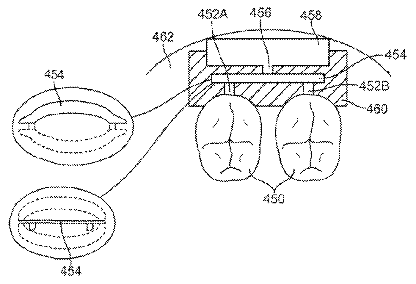
FIG. 3 shows an exemplary cross-sectional view showing the coupling of the sound transducer to one or more teeth 450. In FIG. 3, a mounting unit 452 such as a retainer-like housing is placed over one or more teeth 450. The mounting unit 452 can also be adhesive or glue or a suitable system to secure the appliance to the teeth 450. An actuator 454 rests above support arms or links 452A and 452B which are mechanically connected to the teeth 450.
In one embodiment, the actuator 454 is a piezoelectric transducer made with PZT. PZT-based compounds (Pb[ZrxTi1-x]O3 0<x<1, also lead zirconium titanate) are ceramic perovskite materials that develop a voltage difference across two of its facets when highly compressed. Being piezoelectric, it develops a voltage difference across two of its faces when compressed (useful for sensor applications), or physically changes shape when an external electric field is applied (useful for actuators and the like). The material is also ferroelectric, which means it has a spontaneous electric polarization (electric dipole) which can be reversed in the presence of an electric field. The material features an extremely large dielectric constant at the morphotropic phase boundary (MPB) near x=0.52. These properties make PZT-based compounds one of the most prominent and useful electroceramics.
The actuator 454 is also connected to a mass 458 through a mass arm 456. In one embodiment, the actuator 454 uses PZT in a rectangular beam bender configuration. The mass 458 can be a tungsten material or any suitable weight such as the battery or control electronics, among others. The support arms or links 452A-452B as well as the mass arm 456 are preferably made from ceramic or alumina which enables acoustic or sound energy to be efficiently transmitted by the mounting unit 454.
The appliance can be a custom oral device. The sound source unit can contain a short-range transceiver that is protocol compatible with the linking unit. For example, the sound source can have a Bluetooth transceiver that communicates with the Bluetooth transceiver linking unit in the appliance. The appliance can then receive the data transmitted over the Bluetooth protocol and drive a bone conduction transducer to render or transmit sound to the user.
The appliance can have a microphone embedded therein. The microphone can be an intraoral microphone or an extraoral microphone. For cellular telephones and other telephones, a second microphone can be used to cancel environmental noise and transmit a user's voice to the telephone. A noise canceller receives signals from the microphones and cancels ambient noise to provide a clean sound capture.
The appliance can have another microphone to pick up ambient sound. The microphone can be an intraoral microphone or an extraoral microphone. In one embodiment, the microphone cancels environmental noise and transmits a user's voice to the remote station. This embodiment provides the ability to cancel environmental noises while transmitting subject's own voice to the actuator 432. As the microphone is in a fixed location (compared to ordinary wireless communication devices) and very close to user's own voice, the system can handle environmental noise reduction that is important in working in high noise areas.
The system couples microphones and voicing activity sensors to a signal processor. The processor executes a detection algorithm, and a denoising code to minimize background acoustic noise. Two microphones can be used, with one microphone being the bone conduction microphone and one which is considered the "signal" microphone. The second microphone captures air noise or ambient noise, whose signal is filtered and subtracted from the signal in the first microphone. In one embodiment, the system runs an array algorithm for speech detection that uses the difference in frequency content between two microphones to calculate a relationship between the signals of the two microphones. As known in the art and discussed in U.S. Pat. No. 7,246,058, the content of which is incorporated by reference, this embodiment can cancel noise without requiring a specific orientation of the array with respect to the signal.
In another embodiment, the appliance can be attached, adhered, or otherwise embedded into or upon a removable oral appliance or other oral device to form a medical tag containing patient identifiable information. Such an oral appliance may be a custom-made device fabricated from a thermal forming process utilizing a replicate model of a dental structure obtained by conventional dental impression methods. The electronic and transducer assembly may receive incoming sounds either directly or through a receiver to process and amplify the signals and transmit the processed sounds via a vibrating transducer element coupled to a tooth or other bone structure, such as the maxillary, mandibular, or palatine bone structure.
In yet another embodiment, microphones can be place on each side of the ears to provide noise cancellation, optimal sound localization and directionality. The microphones can be placed inside or outside the ears. For example, the microphones can be placed either at the opening or directly with the user's ear canals. Each of the systems includes a battery, a signal processor, a transmitter, all of which can be positioned in a housing that clips onto the ear which, rests behind the ear between the pinna and the skull, or alternatively can be positioned in the ear's concha. The transmitter is connected to a wire/antenna that in turn is connected to the microphone. Each transmitter transmits information to a receiver that activates a transducer that is powered by a battery. Each side of the head can have one set of receiver, transducer and battery. This embodiment provides a bone conduction hearing aid device with dual externally located microphones that are placed at the entrance to or in the ear canals and an oral appliance containing dual transducers in communication with each other. The device will allow the user to enjoy the most natural sound input due to the location of the microphone which takes advantage of the pinna for optimal sound localization (and directionality).
In another embodiment, the microphones receive sound signals from both sides of the head, processes those signals to send a signal to the transducer on the side of the head where the sound is perceived by the microphone to be at a higher sound level. A phase-shifted signal is sent to the transducer on the opposite side of the head. These sounds will then "add" in the cochlea where the sound is louder and "cancel" on the opposite cochlea providing the user with the perception of directionality of the sound.
In yet another embodiment, the microphone at the first ear receives sound signals from the first side of the head, processes those signal to send a signal to the transducer on that same or first side of the oral appliance. A second microphone at the second ear receives a sound signal that is lower in amplitude and delayed in respect to the sound sensed by the first microphone due to head shadowing and physical separation of the microphones, and sends a corresponding signal to the second transducer on the second side of the oral appliance. The sound signals from the transducers will be perceived by each cochlea on each side of the head as being different in amplitude and phase, which will result in the perception of directionality by the user.
In one embodiment where the microphone is mounted in the user's ear canal, components such as the battery, the signal processor, and the transmitter can either be located behind the ear or within the folds of the pinna. The human auricle is an almost rudimentary, usually immobile shell that lies close to the side of the head with a thin plate of yellow fibrocartilage covered by closely adherent skin. The cartilage is molded into clearly defined hollows, ridges, and furrows that form an irregular, shallow funnel. The deepest depression, which leads directly to the external auditory canal, or acoustic meatus, is called the concha. It is partly covered by two small projections, the tonguelike tragus in front and the antitragus behind. Above the tragus a prominent ridge, the helix, arises from the floor of the concha and continues as the incurved rim of the upper portion of the auricle. An inner, concentric ridge, the antihelix, surrounds the concha and is separated from the helix by a furrow, the scapha, also called the fossa of the helix. The lobule, the fleshy lower part of the auricle, is the only area of the outer ear that contains no cartilage. The auricle also has several small rudimentary muscles, which fasten it to the skull and scalp. In most individuals these muscles do not function, although some persons can voluntarily activate them to produce limited movements. The external auditory canal is a slightly curved tube that extends inward from the floor of the concha and ends blindly at the tympanic membrane. In its outer third the wall of the canal consists of cartilage; in its inner two-thirds, of bone. The anthelix (antihelix) is a folded "Y" shaped part of the ear. The antitragus is the lower cartilaginous edge of the conchal bowl just above the fleshy lobule of the ear. The microphone is connected with the transmitter through the wire and antenna. The placement of the microphone inside the ear canal provides the user with the most natural sound input due to the location of the microphone which takes advantage of the pinna for optimal sound localization (and directionality) when the sounds are transmitted to the cochlea using a straight signal and "phase-shifted" signal to apply directionality to the patient. High quality sound input is captured by placing the microphones within or at the entrance of the ear canal which would allow the patient to use the sound reflectivity of the pinna as well as improved sound directionality due to the microphone placement. The arrangement avoids the need to separate the microphone and speaker to reduce the chance of feedback and allows placement of the microphone to take advantage of the sound reflectivity of the pinna. The system also allows for better sound directionality due to the two bone conduction transducers being in electrical contact with each other. With the processing of the signals prior to being sent to the transducers and the transducers able to communicate with each other, the system provides the best sound localization possible.
The appliance can include a data storage device such as a solid state memory or a flash storage device. The content of the data storage device can be encrypted for security. The linking unit can transmit encrypted data for secure transmission if desired.
The appliance may be fabricated from various polymeric or a combination of polymeric and metallic materials using any number of methods, such as computer-aided machining processes using computer numerical control (CNC) systems or three-dimensional printing processes, e.g., stereolithography apparatus (SLA), selective laser sintering (SLS), and/or other similar processes utilizing three-dimensional geometry of the patient's dentition, which may be obtained via any number of techniques. Such techniques may include use of scanned dentition using intra-oral scanners such as laser, white light, ultrasound, mechanical three-dimensional touch scanners, magnetic resonance imaging (MRI), computed tomography (CT), other optical methods, etc.
In forming the removable oral appliance, the appliance may be optionally formed such that it is molded to fit over the dentition and at least a portion of the adjacent gingival tissue to inhibit the entry of food, fluids, and other debris into the oral appliance and between the transducer assembly and tooth surface. Moreover, the greater surface area of the oral appliance may facilitate the placement and configuration of the assembly onto the appliance.
Additionally, the removable oral appliance may be optionally fabricated to have a shrinkage factor such that when placed onto the dentition, oral appliance may be configured to securely grab onto the tooth or teeth as the appliance may have a resulting size slightly smaller than the scanned tooth or teeth upon which the appliance was formed. The fitting may result in a secure interference fit between the appliance and underlying dentition.
In one variation, an extra-buccal transmitter assembly located outside the patient's mouth may be utilized to receive auditory signals for processing and transmission via a wireless signal to the electronics and/or transducer assembly positioned within the patient's mouth, which may then process and transmit the processed auditory signals via vibratory conductance to the underlying tooth and consequently to the patient's inner ear. The transmitter assembly, as described in further detail below, may contain a microphone assembly as well as a transmitter assembly and may be configured in any number of shapes and forms worn by the user, such as a watch, necklace, lapel, phone, belt-mounted device, etc.
FIG. 4A illustrates a schematic representation of one variation of two-way communication assembly 14 utilizing an extra-buccal transmitter assembly 22, which may generally comprise microphone 30 for receiving sounds and which is electrically connected to processor 32 for processing the auditory signals. Processor 32 may be connected electrically to transmitter 34 for transmitting the processed signals to the electronics and/or transducer assembly 16 disposed upon or adjacent to the user's teeth. The microphone 30 and processor 32 may be configured to detect and process auditory signals in any practicable range, but may be configured in one variation to detect auditory signals ranging from, e.g., 250 Hertz to 20,000 Hertz.
With respect to microphone 30, a variety of various microphone systems may be utilized. For instance, microphone 30 may be a digital, analog, and/or directional type microphone. Such various types of microphones may be interchangeably configured to be utilized with the assembly, if so desired.
Power supply 36 may be connected to each of the components in transmitter assembly 22 to provide power thereto. The transmitter signals 24 may be in any wireless form utilizing, e.g., radio frequency, ultrasound, microwave, Blue Tooth.RTM. (BLUETOOTH SIG, INC., Bellevue, Wash.), etc. for transmission to assembly 16. Assembly 22 may also optionally include one or more input controls 28 that a user may manipulate to adjust various acoustic parameters of the electronics and/or transducer assembly 16, such as acoustic focusing, volume control, filtration, muting, frequency optimization, sound adjustments, and tone adjustments, etc.
The signals transmitted 24 by transmitter 34 may be received by electronics and/or transducer assembly 16 via receiver 38, which may be connected to an internal processor for additional processing of the received signals. The received signals may be communicated to transducer 40, which may vibrate correspondingly against a surface of the tooth to conduct the vibratory signals through the tooth and bone and subsequently to the middle ear to facilitate hearing of the user. Transducer 40 may be configured as any number of different vibratory mechanisms. For instance, in one variation, transducer 40 may be an electromagnetically actuated transducer. In other variations, transducer 40 may be in the form of a piezoelectric crystal having a range of vibratory frequencies, e.g., between 250 to 4000 Hz.
Power supply 42 may also be included with assembly 16 to provide power to the receiver, transducer, and/or processor, if also included. Although power supply 42 may be a simple battery, replaceable or permanent, other variations may include a power supply 42 which is charged by inductance via an external charger. Additionally, power supply 42 may alternatively be charged via direct coupling to an alternating current (AC) or direct current (DC) source. Other variations may include a power supply 42 which is charged via a mechanical mechanism, such as an internal pendulum or slidable electrical inductance charger as known in the art, which is actuated via, e.g., motions of the jaw and/or movement for translating the mechanical motion into stored electrical energy for charging power supply 42.
In another variation of assembly 16, rather than utilizing an extra-buccal transmitter, two-way communication assembly 50 may be configured as an independent assembly contained entirely within the user's mouth, as shown in FIG. 4B. Accordingly, assembly 50 may include an internal microphone 52 in communication with an on-board processor 54. Internal microphone 52 may comprise any number of different types of microphones, as described above. Processor 54 may be used to process any received auditory signals for filtering and/or amplifying the signals and transmitting them to transducer 56, which is in vibratory contact against the tooth surface. Power supply 58, as described above, may also be included within assembly 50 for providing power to each of the components of assembly 50 as necessary.
In yet other variations, vibrations may be transmitted directly into the underlying bone or tissue structures rather than transmitting directly through the tooth or teeth of the user.
For any of the variations described above, they may be utilized as a single device or in combination with any other variation herein, as practicable, to achieve the desired hearing level in the user. Moreover, more than one oral appliance device and electronics and/or transducer assemblies may be utilized at any one time.
Moreover, each of the different transducers can also be programmed to vibrate in a manner which indicates the directionality of sound received by the microphone worn by the user. For example, different transducers positioned at different locations within the user's mouth can vibrate in a specified manner by providing sound or vibrational queues to inform the user which direction a sound was detected relative to an orientation of the user. For instance, a first transducer located, e.g., on a user's left tooth, can be programmed to vibrate for sound detected originating from the user's left side. Similarly, a second transducer located, e.g., on a user's right tooth, can be programmed to vibrate for sound detected originating from the user's right side. Other variations and queues may be utilized as these examples are intended to be illustrative of potential variations.
In variations where the one or more microphones are positioned in intra-buccal locations, the microphone may be integrated directly into the electronics and/or transducer assembly, as described above. However, in additional variation, the microphone unit may be positioned at a distance from the transducer assemblies to minimize feedback.
Modification of the above-described embodiments of the intraoral appliance and methods for carrying out the invention, combinations between different variations as practicable, and variations of aspects of the invention that are obvious to those of skill in the art are intended to be within the scope of the claims.
* * * * *
References
D00000
D00001
D00002
D00003
D00004
D00005
D00006
D00007
D00008
XML
uspto.report is an independent third-party trademark research tool that is not affiliated, endorsed, or sponsored by the United States Patent and Trademark Office (USPTO) or any other governmental organization. The information provided by uspto.report is based on publicly available data at the time of writing and is intended for informational purposes only.
While we strive to provide accurate and up-to-date information, we do not guarantee the accuracy, completeness, reliability, or suitability of the information displayed on this site. The use of this site is at your own risk. Any reliance you place on such information is therefore strictly at your own risk.
All official trademark data, including owner information, should be verified by visiting the official USPTO website at www.uspto.gov. This site is not intended to replace professional legal advice and should not be used as a substitute for consulting with a legal professional who is knowledgeable about trademark law.