User interface apparatus and methods
Ingerman , et al. Nov
U.S. patent number 10,481,878 [Application Number 12/576,027] was granted by the patent office on 2019-11-19 for user interface apparatus and methods. This patent grant is currently assigned to OBJECTSTORE, INC.. The grantee listed for this patent is Patrick Curley, Mark Ingerman. Invention is credited to Patrick Curley, Mark Ingerman.


View All Diagrams
| United States Patent | 10,481,878 |
| Ingerman , et al. | November 19, 2019 |
User interface apparatus and methods
Abstract
In one aspect, the invention provides a digital data processing system for information storage and retrieval that includes a first digital data processor (e.g., personal computer, workstation, server, mainframe, etc.) coupled to a second digital data processor and a data store (e.g., a RDF data store, relational database, etc.). The first digital data processor creates, reads, updates and/or deletes data from the data store (i.e., "CRUD" operations) based on a model generated by the first digital data processor. The model comprises an ontology and a set of constraints that are applied to data characterized by the ontology.
| Inventors: | Ingerman; Mark (Newton, MA), Curley; Patrick (Winchester, MA) | ||||||||||
|---|---|---|---|---|---|---|---|---|---|---|---|
| Applicant: |
|
||||||||||
| Assignee: | OBJECTSTORE, INC. (Austin,
TX) |
||||||||||
| Family ID: | 42099794 | ||||||||||
| Appl. No.: | 12/576,027 | ||||||||||
| Filed: | October 8, 2009 |
Prior Publication Data
| Document Identifier | Publication Date | |
|---|---|---|
| US 20100094805 A1 | Apr 15, 2010 | |
Related U.S. Patent Documents
| Application Number | Filing Date | Patent Number | Issue Date | ||
|---|---|---|---|---|---|
| 61104211 | Oct 9, 2008 | ||||
| Current U.S. Class: | 1/1 |
| Current CPC Class: | G06F 8/35 (20130101); G06F 16/78 (20190101) |
| Current International Class: | G06F 7/00 (20060101); G06F 8/35 (20180101); G06F 16/78 (20190101) |
| Field of Search: | ;707/705,713,781 |
References Cited [Referenced By]
U.S. Patent Documents
| 4701130 | October 1987 | Whitney et al. |
| 4895518 | January 1990 | Arnold et al. |
| 4953106 | August 1990 | Gansner et al. |
| 5119465 | June 1992 | Jack et al. |
| 5129043 | July 1992 | Yue |
| 5199068 | March 1993 | Cox |
| 5259766 | November 1993 | Sack et al. |
| 5267865 | December 1993 | Lee et al. |
| 5270920 | December 1993 | Pearse et al. |
| 5301270 | April 1994 | Steinberg et al. |
| 5310349 | May 1994 | Daniels et al. |
| 5311422 | May 1994 | Loftin et al. |
| 5326270 | July 1994 | Ostby et al. |
| 5333254 | July 1994 | Robertson |
| 5339390 | August 1994 | Robertson et al. |
| 5374932 | December 1994 | Wyschogrod et al. |
| 5379387 | January 1995 | Carlstedt et al. |
| 5381332 | January 1995 | Wood |
| 5395243 | March 1995 | Lubin et al. |
| 5421730 | June 1995 | Lasker, III et al. |
| 5450480 | September 1995 | Man et al. |
| 5463682 | October 1995 | Fisher et al. |
| 5499293 | March 1996 | Behram et al. |
| 5519618 | May 1996 | Kastner et al. |
| 5548506 | August 1996 | Srinivasan |
| 5579486 | November 1996 | Oprescu et al. |
| 5597312 | January 1997 | Bloom et al. |
| 5608789 | March 1997 | Fisher et al. |
| 5634053 | May 1997 | Noble et al. |
| 5655118 | August 1997 | Heindel et al. |
| 5732192 | March 1998 | Malin et al. |
| 5745753 | April 1998 | Mosher, Jr. |
| 5761063 | June 1998 | Jannette et al. |
| 5765140 | June 1998 | Knudson et al. |
| 5788504 | August 1998 | Rice et al. |
| 5795155 | August 1998 | Morrel-Samuels |
| 5809212 | September 1998 | Shasha |
| 5822780 | October 1998 | Schutzman |
| 5826077 | October 1998 | Blakeley et al. |
| 5826252 | October 1998 | Wolters, Jr. et al. |
| 5829983 | November 1998 | Koyama et al. |
| 5832483 | November 1998 | Barker |
| 5841673 | November 1998 | Kobayashi et al. |
| 5873076 | February 1999 | Barr et al. |
| 5875441 | February 1999 | Nakatsuyama et al. |
| 5881269 | March 1999 | Dobbelstein |
| 5907837 | May 1999 | Ferrel et al. |
| 5935249 | August 1999 | Stern et al. |
| 5974441 | October 1999 | Rogers et al. |
| 5974443 | October 1999 | Jeske |
| 5983267 | November 1999 | Shklar et al. |
| 5987415 | November 1999 | Breese et al. |
| 5995958 | November 1999 | Xu |
| 6012098 | January 2000 | Bayeh et al. |
| 6035412 | March 2000 | Tamer et al. |
| 6044373 | March 2000 | Gladney et al. |
| 6044466 | March 2000 | Anand et al. |
| 6078982 | June 2000 | Du et al. |
| 6085188 | July 2000 | Bachmann et al. |
| 6094652 | July 2000 | Faisal |
| 6122632 | September 2000 | Botts et al. |
| 6125363 | September 2000 | Buzzeo et al. |
| 6130679 | October 2000 | Chen et al. |
| 6137797 | October 2000 | Bass et al. |
| 6144997 | November 2000 | Lamming et al. |
| 6151595 | November 2000 | Pirolli et al. |
| 6151624 | November 2000 | Teare et al. |
| 6154738 | November 2000 | Call |
| 6177932 | January 2001 | Galdes et al. |
| 6182085 | January 2001 | Eichstaedt et al. |
| 6185516 | February 2001 | Hardin et al. |
| 6185534 | February 2001 | Breese et al. |
| 6212502 | April 2001 | Ball et al. |
| 6240417 | May 2001 | Eastwick et al. |
| 6243713 | June 2001 | Nelson et al. |
| 6246320 | June 2001 | Monroe |
| 6266668 | July 2001 | Vanderveldt et al. |
| 6308163 | October 2001 | Du et al. |
| 6330554 | December 2001 | Altschuler et al. |
| 6341277 | January 2002 | Coden et al. |
| 6360330 | March 2002 | Mutalik et al. |
| 6369819 | April 2002 | Pitkow et al. |
| 6380910 | April 2002 | Moustakas et al. |
| 6381738 | April 2002 | Choi et al. |
| 6389429 | May 2002 | Kane et al. |
| 6389460 | May 2002 | Stewart et al. |
| 6393423 | May 2002 | Goedken |
| 6396885 | May 2002 | Ding et al. |
| 6405211 | June 2002 | Sokol et al. |
| 6405251 | June 2002 | Bullard et al. |
| 6415283 | July 2002 | Conklin |
| 6418413 | July 2002 | DeMarcken et al. |
| 6418448 | July 2002 | Sarkar |
| 6426723 | July 2002 | Smith et al. |
| 6427151 | July 2002 | Chan et al. |
| 6429870 | August 2002 | Chen et al. |
| 6437799 | August 2002 | Shinomi et al. |
| 6446200 | September 2002 | Ball et al. |
| 6446256 | September 2002 | Hyman et al. |
| 6463440 | October 2002 | Hind et al. |
| 6473467 | October 2002 | Wallace et al. |
| 6493331 | December 2002 | Walton et al. |
| 6493399 | December 2002 | Xia et al. |
| 6496833 | December 2002 | Goldberg et al. |
| 6509898 | January 2003 | Chi et al. |
| 6529899 | March 2003 | Kraft et al. |
| 6530079 | March 2003 | Choi et al. |
| 6539374 | March 2003 | Jung |
| 6542912 | April 2003 | Meltzer et al. |
| 6546406 | April 2003 | DeRose et al. |
| 6556983 | April 2003 | Altschuler et al. |
| 6571222 | May 2003 | Matsumoto et al. |
| 6577769 | June 2003 | Kenyon et al. |
| 6583800 | June 2003 | Ridgley et al. |
| 6594662 | July 2003 | Sieffert et al. |
| 6598043 | July 2003 | Baclawski |
| 6606613 | August 2003 | Altschuler et al. |
| 6625657 | September 2003 | Bullard |
| 6636848 | October 2003 | Aridor et al. |
| 6640284 | October 2003 | Shaw et al. |
| 6643638 | November 2003 | Xu |
| 6643652 | November 2003 | Helgeson et al. |
| 6678679 | January 2004 | Bradford |
| 6701314 | March 2004 | Conover et al. |
| 6721747 | April 2004 | Lipkin |
| 6725227 | April 2004 | Li |
| 6751663 | June 2004 | Farrell et al. |
| 6754475 | June 2004 | Harrison et al. |
| 6757708 | June 2004 | Craig et al. |
| 6771706 | August 2004 | Ling et al. |
| 6772148 | August 2004 | Baclawski |
| 6778971 | August 2004 | Altschuler et al. |
| 6785341 | August 2004 | Walton et al. |
| 6792420 | September 2004 | Stephen Chen et al. |
| 6804688 | October 2004 | Kobayashi et al. |
| 6856992 | February 2005 | Britton et al. |
| 6901438 | May 2005 | Davis et al. |
| 6925457 | August 2005 | Britton et al. |
| 6927728 | August 2005 | Vook et al. |
| 6934702 | August 2005 | Faybishenko et al. |
| 6940917 | September 2005 | Menon et al. |
| 6954749 | October 2005 | Greenblatt et al. |
| 6963875 | November 2005 | Moore et al. |
| 7027055 | April 2006 | Anderson |
| 7047411 | May 2006 | DeMello et al. |
| 7058367 | June 2006 | Luo et al. |
| 7058637 | June 2006 | Britton et al. |
| 7117260 | October 2006 | Bimson et al. |
| 7171145 | January 2007 | Takeuchi et al. |
| 7171415 | January 2007 | Kan et al. |
| 7289793 | October 2007 | Norwood et al. |
| 7302440 | November 2007 | Britton et al. |
| 7313588 | December 2007 | Shotton, Jr. et al. |
| 7318055 | January 2008 | Britton et al. |
| 7505989 | March 2009 | Gardner |
| 7613712 | November 2009 | Greenblatt et al. |
| 7640239 | December 2009 | Britton et al. |
| 7676489 | March 2010 | Kaiser |
| 7716056 | May 2010 | Weng |
| 8112416 | February 2012 | Liu |
| 8335778 | December 2012 | Ghosh |
| 8392483 | March 2013 | Lawrence |
| 8612208 | December 2013 | Cooper |
| 8768923 | July 2014 | Drumm |
| 9092522 | July 2015 | Altenhofen |
| 9298855 | March 2016 | Aggarwal |
| 2001/0047355 | November 2001 | Anwar |
| 2002/0042831 | April 2002 | Capone et al. |
| 2002/0049603 | April 2002 | Mehra et al. |
| 2002/0049788 | April 2002 | Lipkin et al. |
| 2002/0059566 | May 2002 | Delcambre et al. |
| 2002/0069134 | June 2002 | Solomon |
| 2002/0078030 | June 2002 | Iwayama et al. |
| 2002/0091678 | July 2002 | Miller et al. |
| 2002/0091710 | July 2002 | Dunham et al. |
| 2002/0091835 | July 2002 | Lentini et al. |
| 2002/0118688 | August 2002 | Jagannathan |
| 2002/0120598 | August 2002 | Shadmon et al. |
| 2002/0133502 | September 2002 | Rosenthal et al. |
| 2002/0143759 | October 2002 | Yu |
| 2002/0177232 | November 2002 | Melker et al. |
| 2002/0178232 | November 2002 | Ferguson |
| 2003/0004934 | January 2003 | Qian |
| 2003/0009239 | January 2003 | Lombardo et al. |
| 2003/0014399 | January 2003 | Hansen et al. |
| 2003/0037145 | February 2003 | Fagan |
| 2003/0050834 | March 2003 | Caplan |
| 2003/0050927 | March 2003 | Hussam |
| 2003/0050929 | March 2003 | Bookman et al. |
| 2003/0061209 | March 2003 | Raboczi et al. |
| 2003/0074352 | April 2003 | Raboczi et al. |
| 2003/0074369 | April 2003 | Scheutze et al. |
| 2003/0088639 | May 2003 | Lentini et al. |
| 2003/0109951 | June 2003 | Hsiung et al. |
| 2003/0182310 | September 2003 | Charnock |
| 2003/0208499 | November 2003 | Bigwood et al. |
| 2003/0229529 | December 2003 | Mui et al. |
| 2004/0034651 | February 2004 | Gupta et al. |
| 2004/0054690 | March 2004 | Hillerbrand et al. |
| 2005/0027563 | February 2005 | Fackler et al. |
| 2005/0055330 | March 2005 | Britton et al. |
| 2005/0060372 | March 2005 | DeBettencourt et al. |
| 2005/0125683 | June 2005 | Matsuyama et al. |
| 2006/0036620 | February 2006 | Bigwood et al. |
| 2006/0053135 | March 2006 | Beaumont |
| 2006/0218123 | September 2006 | Chowdhuri |
| 2006/0271563 | November 2006 | Angelo et al. |
| 2006/0277227 | December 2006 | Britton et al. |
| 2007/0078815 | April 2007 | Weng |
| 2007/0081197 | April 2007 | Omoigui |
| 2008/0109420 | May 2008 | Britton et al. |
| 2008/0109485 | May 2008 | Britton et al. |
| 2008/0195591 | August 2008 | Lei |
| 1132847 | Sep 2001 | EP | |||
| 2343763 | May 2000 | GB | |||
| WO-9722096 | Jun 1997 | WO | |||
| WO-9805018 | Feb 1998 | WO | |||
| WO-9810399 | Mar 1998 | WO | |||
| WO-9824020 | Jun 1998 | WO | |||
| WO-9927460 | Jun 1999 | WO | |||
Other References
|
"An Overview of the NEDSS Initiative", website for the Centers for Disease Control and Prevention, http://www.cdc.gov/nedss/About/overview.html, printed Nov. 14, 2005, 2 pages. cited by applicant . "Background on Public Health Surveillance", website for the Centers for Disease Control and Prevention, http://www.cdc.gov/nedss/About/purpose.htm, printed Nov. 14, 2005, 3 pages. cited by applicant . "Description of the NEDSS Base System," Mar. 28, 2001, 5 pages. cited by applicant . "Inkling: RDF Query Using SquishQL," downloaded from http://swordfish.rdfweb.org/rdfquery/ on Mar. 20, 2003, 2 pages. cited by applicant . "MaestroTM Public Health Suite," Orion International website, http://www.orionhealth.com/maestro_overview.htm, printed Jan. 18, 2005, 3 pages. cited by applicant . "National Electronic Disease Surveillance System (NEDSS): A standards-Based Approach to Connect: Public Health and Clinical Medicine", J. Public Health Management Practice, 2001. 7(6], 43-508 pages. cited by applicant . "NEDSS and NEDSS PAMs Business Discovery Statement", Version 1.2, Mar. 9, 2002, 23 pages. cited by applicant . "NEDSS Base System Fact Sheet", website for the Centers for Disease Control and Prevention, 2 pages, Apr. 25, 2001. cited by applicant . "Nedss Logical Data Model (NLDM) Overview and Users' Guide", Version 1.0, 92 pages, Feb. 13, 2002. cited by applicant . "NEDSS Systems Architecture", Version 2.0, Apr. 15, 2001, 5 pages. cited by applicant . "Overview of PHIN", Centers for Disease Control and Prevention website, http://www.cdc.gov/phin, printed Jan. 18, 2005, 3 pages. cited by applicant . "rdfDB Query Language," downloaded from http://www.guha.com/rdfdb/query.html on Mar. 20, 2003, 4 pages. cited by applicant . "RDQL--RDF Data Query Language," Hewlett-Packard Company, .COPYRGT. 1994-2003, downloaded from http://www.hpl.hp.com/semweb/rdql.htm on Mar. 20, 2003, 3 pages. cited by applicant . "The Rete Algorithm," http://herzberg.ca.sandia.gov/jess/docs/52/rete.html, 3 pages, downloaded on Feb. 20, 2003. cited by applicant . "The Surveillance and Monitoring Component of the Public Health Information Network", website for the Centers for Disease Control and Prevention, http://www.cdc.gov/nedss, printed Nov. 14, 2005, 2 pages. cited by applicant . Public Health Information Network, The Association of State and Territorial Health Officials website, http://www.astho.org/?template=public_health_info_network.html, printed Jan. 18, 2005, 2 pages. cited by applicant . Amann, B. et al., "Integrating Ontologies and Thesauri for RDF Schema Creation and Metadata Querying" Mar. 6, 2001. cited by applicant . Beckett, D. "The Design and Implementation of the Redland RDF Application Framework," Copyright WWW01 May 2-5, 2001. Retrieved from http:www10.org/cdrom/papers/490/. cited by applicant . Beckett, Dave Dave Beckett's Resource Description Framework (RDF) Resource Guide, available at http://planetrdf.com/guide, last updated Sep. 23, 2005, 26 pages. cited by applicant . Berners-Lee et al "Web Architecture: Describing and Exchanging Data," W3C Recommendations, Jun. 7, 1999, http://www.w3.org/1999/06/07-WebData. cited by applicant . Berners-Lee, "Semantic Web Road Map," W3C Recommendations, Sep. 1998, http://www.w3.org/DesignIssues/Semantic.html. cited by applicant . Berners-Lee, "What a semantic web can represent," W3C Recommendations, Sep. 1998. cited by applicant . Berners-Lee, Tim "Information Management: A Proposal," Mar. 1989, May 1990; 14 pages. cited by applicant . Berniers-Lee et al, "The Enquire Manual," Oct. 1980, http://infomesh.net/2001/enriquire/manual/. cited by applicant . Berniers-Lee et al. RFC 2396: Uniform Resource Identifiers (URI): Generic Syntax (Aug. 1998) http://www.cs.tut.fi/.about.jkorpela/rfc/2396/full.html, 23 pages, downloaded on Feb. 20, 2003. cited by applicant . Bonifati, "Comparative Analysis of Five XML Query Languages," SIGMOD Record, vol. 29, No. 1, Mar. 2000. cited by applicant . Bray, Tim et al. "Extensible Markup Language," W3C Recommendations, Feb. 10, 1998, http://www.w3.org/TR/1998/REC-xml-19980210. cited by applicant . Brickley, Dan "RDF Query in Javascript demo," W3C website, Jul. 28, 2001, http://www.w3.org/1999/11/11-WWWProposal/rdfqdemo.html. cited by applicant . Brickley, Dan "Semantic Web History: Nodes and Arcs 1989-1999," The WWW Proposal and RDF, revised Mar. 2001 http:www.w3.org/1999/11/11-WWWProposal/. cited by applicant . Brickley, Dan et al. "SWIPE 0.1 specification" Pub. 2001. Retrieved from: http:rdfweb.org/2001/01/swipe/. cited by applicant . Brickley, Dan et al., "RDF, squish etc." Pub on the web Nov. 26, 2000. Retrieved from http://www.ilrt.bris.ac.uk/discovery/2000/111/QL/QL.txt. cited by applicant . Bucher, Alex et al. "Discovering Internet Marketing Intelligence through Online Analytical Web Usage Mining," SIGMOD Record, vol. 27, No. 4, Dec. 1998. cited by applicant . Buneman et al "Interaction between Path and Type Constraints" PODS 1999, pp. 56-67. cited by applicant . Card et al., "Readings in Information Visualizing Using Vision to Think", 1999, Morgan Kaufmann, p. 298. cited by applicant . Carr, Leslie et al. "The Evolution of Hypertext Link Services," ACM Computing Surveys, vol. 31, No. 4es, Dec. 1999. cited by applicant . Chen, James et al "A Distributed Multi-Agent System for Collaborative Information Management and Sharing," RBAC 2000, Berlin, Germany ISBN 1-58113-259-x/00/07; 2000. cited by applicant . Churchill, R. et al. "RDT Technical Overview" Mozilla.org. Last modified 11, 1999. Retrieved from http://www.mozill.org/rdf/doc/api.html. cited by applicant . Clark, James Editor "XSL Transformations," W3C Recommendations, Nov. 16, 1999, http://www.w3.org/TR/xsIt. cited by applicant . Cowan, John et al. "XML Information Set," W3C Recommendations, May 17, 1999, http://www.w3.org/TR/1999/WD-xml-infoset-19990517. cited by applicant . Crestani, Fabio "Vocal Access to a Newspaper Archive: Design Issues and Preliminary Investigations," International Computer Science Institute; Mar. 1999. cited by applicant . Dublin Core Metadata Initiative, available at http://dublincore.org, web page last updated Mar. 31 2009, copyright 1995-2009; 1 page. cited by applicant . Extensible Markup Language (XML), W3C Sematic Web, http://www.w3.org/XML/ ; last updated Apr. 5, 2009; copyright 1996-2003; 5 pages. cited by applicant . Extensible Markup Language Activity Statement , W3C Ubiquitous Web, http://www.w3.org/XML/Activity; downloaded Apr. 10, 2009; 3 pages. cited by applicant . Fan, Wenfei, "Integrity Constraints for XML," ACM Symposium on Principles of Database Systems archive Proceedings of the nineteenth ACM SIGMOD-SIGACT-SIGART symposium on Principles of database systems; Dallas, Texas, United States; pp. 23-34 ; Year of Publication: 2000. cited by applicant . Fensel, D. "Ontobroker: Or How to Enable Intelligent Access to the WWW," Proceedings of the 11.sup.th Banff Knowledge Acquisition for Knowledge-Based System Workshop (KAW98), Banaff, Kanada, Apr. 1998. cited by applicant . Forgy, Charles L. "Rete: A Fast Algorithm for the Many Pattern/Many Object Pattern Match Problem," Artifical Intelligence vol. 19 (1982) pp. 17-37. cited by applicant . Frank Manola, "Towards a Richer Object Model", SIGMOD Record, vol. 27, No. 1, Mar. 1998, 6 pages. cited by applicant . Gandon, Fabien et al. "A Multi-Agent System to Support Exploiting an XML-based Corporate Memory" INRIA, ACACI Project, 2004 Route des Lucioles, 06902 Sophia Antipolis, France, Proc. of the Third Int. Conf. On Practical Aspects of Knowledge Management (PAKM2000) Basel, Swwitzerland, Oct. 30-31, 2000, (U.Reimer, ed.). cited by applicant . Grant, J and Beckett, D. "RDF Test Cases," W3C Recommendations, Dec. 2003, http://www.w3.org/TR/2003/PR-rdf-testcases-20031215/. cited by applicant . Gray, M., "Semantic Labeling" HIVE. May 14, 1999. Retrieved from: htttp://hive.sourceforge.net/mkgray-thesis/html/node8.html. cited by applicant . Halpin, Harry et al "W3C Semantic Web Activity," W3C Sematic Web, http://www.w3.org/2001/sw/; last updated Apr. 6, 2009, copyright 1994-2009. cited by applicant . Hayes, Patrick Editor "RDF Semantic," W3C Recommendation, Feb. 2004, http://www.w3.org/TR/2004/REC-rdf-mt-20040210/. cited by applicant . Jenkins, C. et al., "Automatic RDF Metadata Generation for Resource," Computer Networks, 1999. cited by applicant . Karvounarakis, G. et al., "Querying Community Web Portals" Pub. 2000. cited by applicant . Kerschberg, L. "Knowledge Management in Heterogenous Data Warehouse Environments," Pub. 2001. cited by applicant . Kerstin Forsberg et al. Extensible use of RDF in a business context. Computer Networks 33 (2000), pp. 347-364: The International Journal of Computer and Telecommunications Networking . Published Jun. 2000. cited by applicant . Lassila, et al "Resource Description Framework (RDF) Model and Syntax Specification," W3C Recommendations, Feb. 22, 1999. cited by applicant . Lois Delcambre et al., "Bundles in Captivity: An Application of Superimposed Information", IEEE 2001, pp. 111-120. cited by applicant . Ludascher, B. Gupta, A. Martone, M.E.Model-based mediation with domain maps. Data Engineering, 2001. Proceedings. 17th International Conference on Publication Date: 2001. pp. 81-90. Meeting Date: Apr. 2-6, 2001. cited by applicant . M. R. Kogalovsky. Systematization of information resources collections in digital libraries. MAIK Nauka/Interperiodica distributed exclusively by Springer Science+Business Media LLC. vol. 26, No. 3 / May 2000, pp. 140-155. cited by applicant . Malhotra, Ashok et al., "XML Schema Requirements," W3C Note, Feb. 15, 1999, http://www.w3.org/TR/NOTE-xml-schema-req. cited by applicant . Manola, Frank Editor "RDF Primer," W3C Working Draft, Mar. 2002, http://www.w3.org/TR/2002/WD-rdf-primer-20020319/. cited by applicant . McGrath et al, "Digital Library Technology for Locating and Accessing Scientific Data," Internationalal Conference on Digital Libraries, Proceedings of the fourth ACM conference on Digital Libraries, Berkley, CA, United States, pp. 188-194, Year of Publication: 1999. ISBN: 1-58113-145-3. cited by applicant . Melnik, Sergey "Building a Distributed Full-Text Index of the Web," WWW10, May 1-5, 2001, Hong Kong ACM 1-58113-348-0/01/00005. cited by applicant . Melnik, Sergey "A Mediation Infrastructure for Digital Library Services," Digital Libraries, San Antonio, TX ACM 2000-581 13-231 x/00/0006; 2000. cited by applicant . Melnik, Sergey, "Storing RDF in a relational database," http://www-db.stanford.edu/ .about.melnik/rdf/db.html, 5 pages, downloaded on 20/20/2003. cited by applicant . Miller, Eric et al., RDF Primer, W3C @@ Editor's Draft Jan. 27, 2002 @@, Copyright 2001, 2002 (MIT,INRIA,Keio) (22 pages). cited by applicant . Miller, L., "Aggregating Recommendations Using RDF," ILRT. Org. Pub. Jan. 10, 1999. cited by applicant . Ouksel, Aris et al. "Semantic Interoperability in Global Information Systems," SIGMOD Record, vol. 28, No. 1, Mar. 1999. cited by applicant . Prudhommeaux, Eric "Check and Visualize you RDF," W3C website, Feb. 15, 2007, http://www.w3.org/RDF/Validator/. cited by applicant . Public Health Information Network Functions and Specifications, Version 1.2--Dec. 18, 2002; Draft; 56 pages. cited by applicant . Published International Search Report (published May 24, 2007) and Written Opinion (dated Feb. 12, 2007) for PCT/US05/005725. cited by applicant . Quinlan, J. R., "Induction of Decision Trees," Machine Learning vol. 1 (1986) pp. 18-106. cited by applicant . RDF Interest Group 1999-2004, available at W3C Semantic Web, http://www.w3.org/RDF/Interest/ ; last updated Dec. 8, 2005; downloaded Apr. 2009. cited by applicant . Resource Description Framework (RDF) Model and Syntax Specification W3C Recommendation (Feb. 22, 1999) http://www.w3.org.TR/1999/REC-rdf-syntax-19990222/, 34 pages, downloaded on Feb. 20, 2003. cited by applicant . Resource Description Framework, (RDF) Schema Specification, W3C Proposed Recommendation Mar. 3, 1999, http://www.w3.org/TR/1999/PR-rdf-schema-19990303/. cited by applicant . Rogers, N. "SWAD--Europe deliverable 4.2: Semantic Web and Web Services: RDF/XML and Soap for Web Data Encoding" Year 2001. cited by applicant . S. Alexaki et al. Managing RDF Metadata for Community Webs. Springer Berlin / Heidelberg. vol. 1921/2000, pp. 140-151. cited by applicant . Semantic Web Workshop 2001. Proceedings of the Second International Workshop on the Semantic Web. SemWeb'2001. S. Staab et al. Hong Kong, China, May 2001. cited by applicant . Semantic Web Workshop: Models, Architectures and Management, Sep. 21, 2000 Conference Review, Intelligence Summer 2001. cited by applicant . Sergey Melnik et al. Representing Order in RDF. Pub. Jan. 7, 2001. Retrieved from:http://infolab.stanfordedu/.about.stefan/daml/order.html. cited by applicant . Shankar, Ravi D. et al., "Epoch: an Ontological Framework to Support Clinical Trials Management", .sup.1Stanford Medical Informatics, Stanford University School of Medicine, Stanford, CA, USA, .sup.2The Immune Tolerance Network, Pittsburgh, PA, USA, pp. 25-32, Nov. 11, 2006, Copyright 2006. cited by applicant . Six, Janet, M. et al, "Effective e Graph Visualization Via Node Grouping", Proceedings of the IEEE Symposium on Information Visualization 2001 (INFOVIS'01) (8 pages). cited by applicant . Suciu, Dan "Managing Web Data," AT&T Labs-Research, SIGMOD 1999, ISSN:0163-5808. cited by applicant . Swick, R. "The Cambridge Communique," W3C Recommendations, Oct. 1999, http://www.w3.org/TR/schema-arch. cited by applicant . Swick, Ralph, "RDF:Weaving the Web of Discovery," Putting it Together, Jun. 1999, pp. 21-25, Year of Publication: 1999, ISSN:1091-3556. cited by applicant . Sycara, Katia et al. "Dynamic Service Matchmaking Among Agents in Open Information," SIGMOD Record, vol. 28, No. 1, Mar. 1999. cited by applicant . Takeda, Koichi, "Site Outlining," IBM Research, Tokyo Research Lab, 1623-14, May 1998. cited by applicant . Technical Reports and Communications, W3C website, http://www.w3.org/TR/ ; last updated Apr. 21, 2009; copyrighted 1994-2006. cited by applicant . Terence Critchlow. Report on XEWA-00: the XML enabled wide-area searches for bioinformatics workshop. ACM> vol. 30 , Issue 1 (Mar. 2001). cited by applicant . Thomas Lee, et al "Information integration with attribution support for corporate profiles," Information integration with attribution support for corporate profiles, Conference on Information and Knowledge Management, Proceedings of the eighth international conference on Information and knowledge management , Kansas City, Missouri, United States ,pp. 423-429 ,Year of Publication: 1999 , ISBN:1-58113-146-1. cited by applicant . Thompson, Craig "Workshop on Compositional Software Architectures Workshop Report," Software Engineering Notes, vol. 23. No. 3, May 1998. cited by applicant . Tudhope et al "Semantically Indexed Hypermedia: Linking Information Disciplines," ACM 2000, www.comp.glam.ac.uk/people/staff/dstudhope. cited by applicant . Web site; http://www.w3.org/DesignIssues/RDFnot.html ; Sep. 27, 2004 ; 8 pages. cited by applicant . William A. Yasnoff et al., "Public health informatics: Improving and transforming public health in the information age" Topics in Health Information Management, Frederick; Aspen Publishers; Feb. 2001; 8 pages. cited by applicant . Supplementary European Search Report for App. No. 03728486.6, dated Aug. 21, 2007. cited by applicant . Sergey Melnik and Stefan Decker, "A Layered Approach to Information Modeling and Interoperability on the Web", Database Group, Stanford Univ., Sep. 4, 2000, 13 pages. cited by applicant . Dan Brickley and Libby Miller, "RDF, SQL and the Semantic Web--A Case Study", www.ilrt.org/discovery/2000/10/swsql/ , latest version Nov. 8, 2000 (initial draft Oct. 31, 2000), 8 pages. cited by applicant . Omelayenko, B., "Learning of Ontologies for the Web: the Analysis of Existent Approaches" Proceedings of the International Workshop on Web Dynamics Held in Conj. With The 8TH Internationsl Conference on Database Theory Jan. 3, 2001 pp. 1-10, XP002378744, London, UK. cited by applicant . Nick, Z.Z. et al., "Web Search Using a Genetic Algorithm" IEEE Internet Computing, vol. 5, No. 2, Mar. 2001, pp. 18-26, XP002378745, USA. cited by applicant . Supplemental European Search Report for European Application No. 02736950.3 dated May 19, 2006, 4 pages. cited by applicant . European Patent Office Communication Pursuant to Article 96(2) for European Applicaiton No. 02741744.2, dated Dec. 8, 2006, 12 pages. cited by applicant . International Search Report for International Appliaction No. PCT/US05/05725, dated Feb. 12, 2007, (9 pages). cited by applicant. |
Primary Examiner: Harper; Eliyah S.
Parent Case Text
This application claims the benefit of priority of U.S. Patent Application Ser. No. 61/104,211 filed Oct. 9, 2008, having the same title hereof, the teachings of which are incorporated herein by reference.
Claims
The invention claimed is:
1. A digital data processing system, comprising: a first digital data processor that when coupled to (i) a second digital data processor and (ii) a data store, coupled to at least the second digital data processor, during operation accesses a model comprising an ontology and a set of constraints that defines how a user of the first digital data processor is allowed to interact with data in the data store, wherein the first digital data processor during operation (i) performs creating, reading, updating and deleting the data from the data store based on code generated from the model and executable by said first digital data processor and (ii) displays a user interface (UI) with masks generated by the second digital data processor that masks, based on one or more constraints defined in the model, a selected portion of one or more data values of the data prior to generation and display of the UI by the first digital data processor.
2. The system of claim 1, wherein the second digital data processor displays a user interface (UI) that performs any of a selected data create, read, update and delete operation.
3. The system of claim 2, wherein the UI is based on code generated from the model by the first digital data processor.
4. The system of claim 2, wherein the UI includes a plurality of data fields, each data field associated with one or more data labels and one or more data values.
5. The system of claim 3, wherein any of the one or more data labels and one or more data values are any of (i) defined by the model, (ii) retrieved by the one or more digital data processors from the data store, and (iii) input by a user.
6. The system of claim 1, wherein the set of constraints include any of security rules, minimum and/or maximum data value character lengths, data value character types, default data values, and field masking.
7. The system of claim 2, wherein the first digital data processor masks a selected portion of one or more data values of the data prior to generation and display of the UI, said masking based on one or more constraints defined in the model.
8. The system of claim 7, wherein the second digital data processor displays a UI that displays portions of the data elements that are not masked.
9. The system of claim 2, wherein the second digital data processor generates a warning in response to user-input entered via the one or more digital data processors.
10. The system of claim 9, wherein the warning is generated in accord with the one or more attributes defined by the model.
11. The system of claim 10, wherein the second digital data processor transmits said warning to a user and/or administrator.
12. A digital data processing system, comprising: multiple digital data processors coupled to a data store, a model stored in a memory of the one of the digital data processors, wherein the model comprises an ontology and a set of constraints that defines how a user of the first digital data processor is allowed to interact with data in the data store, a first of the multiple digital data processors when operating performs (i) creating, reading, updating and deleting data from the data store based on code generated from the model and executable by a second of the multiple digital data processors and (ii) displays a user interface (UI) generated by the second digital data processor that masks, based on one or more constraints defined in the model, a selected portion of one or more data values of the data prior to generation and display of the UI by the first digital data processor.
13. The system of claim 12, wherein the first of the multiple digital data processors includes code generated from the second of the one or more digital data processors to display a user interface (UI) based on the model.
14. The system of claim 13, wherein the UI includes a plurality of data fields, each data field associated with one or more attributes and one or more elements of data in the data store.
15. The system of claim 14, wherein the model defines the one or more attributes, including any of a label, default value, character type, maximum character length, minimum character length, and mask attributes.
16. The system of claim 14, wherein the one or more elements of data associated with each data field are any of (i) defined by the model, (ii) retrieved by the one or more digital data processors from the data store, and/or (iii) input by a user.
17. The system of claim 14, wherein the code generated by the second of the digital data processors to display the UI is capable of generating the UI to display portions of the data elements that are not masked, and does not display the masked portions of said elements.
18. The system of claim 14, wherein the first of the digital data processors generate a warning in response to user-input entered via the first of the digital data processors.
19. The system of claim 14, wherein the warning is generated in accord with the one or more attributes defined by the model.
20. The system of claim 14, wherein the second digital data processors transmits said warning to a user and/or administrator.
21. A digital data processing system, comprising: one or more digital data processors coupled to a data store, a model for executing on the one or more digital data processors, wherein the model comprises an ontology and a set of constraints that defines how a user of the first digital data processor is allowed to interact with data in the data store, the one or more digital data processors when operating executes code, generated from the model by said one or more digital data processors, for (i) creating, reading, updating and deleting data from the data store and (ii) displaying a user interface (UI) generated by one or more of the digital data processors that masks, based on one or more constraints defined in the model, a selected portion of one or more data values of the data prior to generation and display of the UI by the first digital data processor.
22. The system of claim 21, wherein the one or more digital data processors comprise a first digital data processor coupled to a second digital data processor.
23. The system of claim 22, wherein the first digital data processor generates the model from at least an ontology and a set of constraints.
24. The system of claim 23, wherein the second digital data processor generates a user interface (UI) based on the model and code generated therefrom by the first digital data processor.
25. The system of claim 23, wherein the second digital data processor any of creates, reads, updates, and deletes data from the data store based on the ontology.
26. The system of claim 24, wherein the ontology at least defines a structure for data in the data store.
27. The system of claim 22, wherein the second digital data processor masks a portion of data read from the data store based on the set of constraints.
28. A digital data processing system, comprising: a first digital data processor coupled to a second digital data processor, a model comprising an ontology and a set of constraints that defines how a user of the first digital data processor is allowed to interact with data in the data store, the first digital data processor during operation displays a user interface (UI) based on the model and executable code generated therefrom by the second digital data processor, the UI having a plurality of data fields, each data field associated with one or more attributes and one or more elements of a data record, and the second digital data processor during operation performs creating, reading, updating and deleting one or more elements of the data record based on UI data field input and generating a user interface (UI) with masks that is displayable by the first digital data processor that masks, based on one or more constraints defined in the model, a selected portion of one or more data values of the data prior to generation and display of the UI by the first digital data processor.
29. The system of claim 28, wherein the model defines the one or more attributes, including any of a label, default value, character type, maximum character length, minimum character length, and mask attributes.
30. The system of claim 28, wherein the one or more elements of a data record associated with each data field are any of (i) defined by the model, (ii) retrieved by the second digital data processor from a digital data store in communications coupling therewith, and/or (iii) input by a user.
31. The system of claim 28, wherein the first digital data processor generates a UI that displays portions of the data record elements that are not masked, and does not display the masked portions of said elements.
32. The system of claim 28, wherein the second digital data processor stores each data record in a data store in communications coupling therewith, said data store specified in the ontology defined in the model.
33. The system of claim 29, wherein the second digital data processor generates a warning in response to user-input entered via the first digital data processor.
34. The system of claim 33 wherein the warning is generated in accord with the one or more attributes defined by the model.
35. The system of claim 33, wherein the first digital data processor displays said warning to a user and/or administrator.
36. A method for generating a user interface (UI), comprising: generating a model comprising an ontology and a set of constraints that defines how a user of the first digital data processor is allowed to interact with data in the data store, and displaying a user interface (UI) based on the model and code generated therefrom, wherein the UI includes a plurality of data fields, each data field associated with one or more attributes and one or more elements of a data record, and, based on one or more constraints defined in the model and UI code generated by a second digital data processor, the UI masks a selected portion of one or more data values of the data prior to generation and display of the UI by the first digital data processor, and executing the code generated from the model to creating, reading, updating and deleting one or more elements of the data record based on UT data field input.
37. The method of claim 36, defining, with the model, the one or more attributes, including any of a label, default value, character type, maximum character length, minimum character length, and mask attributes.
38. The method of claim 36, comprising displaying portions of the one or more elements that are not masked.
39. The method of claim 36, comprising storing each data record in a data store specified in the ontology defined in the model.
40. The method of claim 37, comprising generating a warning in response to user input.
41. The method of claim 40, wherein the warning is generated in accord with the one or more attributes defined by the model.
42. The method of claim 40, displaying said warning to a user and/or administrator.
43. The system of claim 18, wherein the warning is generated in accord with the one or more attributes defined by the model.
44. The system of claim 18, wherein the first code to generate the UI is capable of displaying digital data processors display said warning to a user and/or administrator.
45. A digital data processing system, comprising: a first digital data processor coupled to (i) a second digital data processor and (ii) a data store, a memory coupled to at least one of the first and second digital data processors, wherein the memory includes a model stored therein and the model comprises an ontology and a set of constraints that defines how a user of the first digital data processor is allowed to interact with data in the data store, wherein the first digital data processor during operation performs (i) any of creating, reading, updating and deleting data from the data store based on code generated from the model and executable by said first digital data processor and (ii) displays a user interface (UI) with masks generated by the second digital data processor that masks, based on one or more constraints defined in the model, a selected portion of one or more data values of the data prior to generation and display of the UI by the first digital data processor.
46. The system of claim 45, wherein the second digital data processor displays a user interface (UI) based on code generated from the model by the first digital data processor.
47. The system of claim 46, wherein the UI includes a plurality of data fields, each data field associated with one or more attributes and one or more elements of data in the data store.
48. The system of claim 46, wherein the model defines the one or more attributes, including any of a label, default value, character type, maximum character length, minimum character length, and mask attributes.
49. The system of claim 46, wherein the one or more elements of data associated with each data field are any of (i) defined by the model, (ii) retrieved by the one or more digital data processors from the data store, and/or (iii) input by a user.
50. The system of claim 49, wherein the second digital data processor displays a UI that displays portions of the data elements that are not masked, and does not display the masked portions of said elements.
51. The system of claim 46, wherein the second digital data processor generates a warning in response to user-input entered via the one or more digital data processors.
Description
BACKGROUND OF THE INVENTION
The invention pertains to digital data processing and, more particularly, to methods and apparatus for facilitating digital data information storage and retrieval operations, e.g., data create, read, update, and delete operations.
In today's marketplace, many advanced data management systems focus on providing back-end support for data storage and retrieval. They are generally geared towards developers, who use Application Programming Interfaces (APIs) supplied with the packages to write "one-off" applications (e.g., with Java Swing) that permit users to create, access, delete and otherwise "interface" with the data. While this facilitates (and, indeed, necessitates) customization, a drawback is increased time and expense at inception and throughout the lifetime of each custom application. This has led to slow adoption of many advanced data management technologies by business enterprises and the like.
One advanced data management technology that is coming to the fore is semantic data management. These are technologies that utilize knowledge space-specific vocabularies to improve data retrieval, if not also data storage. In addition to the hurdles discussed above, however, current semantic data packages typically do not provide security features desired by many enterprises (e.g., financial institutions). The packages focus, instead, on improving data retrieval and, as a consequence, necessitate increased attention to security by application developers.
An object of the invention is to provide improved methods and apparatus for digital data processing.
A further object of the invention is to provide such methods and apparatus as facilitate digital data information storage and retrieval. A related object of the invention is to provide such methods and apparatus as facilitate data creation, retrieval, update and deletion ("CRUD") operations.
A further related object is to provide such methods and apparatus as facilitate the development and life-time maintenance of data management applications.
A still further object of the invention is to provide such methods and apparatus as ensure data security.
A yet still further object of the invention is to provide such methods and apparatus as are adapted for use with semantic data systems, as well as other advanced data technologies.
SUMMARY OF THE INVENTION
The foregoing objects are among those attained by the invention which provides, in one aspect, a digital data processing system for information storage and retrieval that includes a first digital data processor (e.g., personal computer, workstation, server, mainframe, etc.) coupled to a second digital data processor and a data store (e.g., a RDF data store, relational database, etc.). The first digital data processor creates, reads, updates and/or deletes data from the data store (i.e., "CRUD" operations) based on a model generated by the first digital data processor. The model comprises an ontology and a set of constraints that are applied to data characterized by the ontology.
In related aspects, the invention provides a digital data processing system for information storage and retrieval as described above in which the first digital data processor displays a user interface (UI) for performing CRUD operations. In further related aspects, the invention provides such a digital data processing system in which the UI is based on the model and code generated therefrom, e.g., by the first digital data processor and/or the second digital data processor. In still further related aspects, the invention provides such a digital data processing system in which the UI includes a plurality of data fields, each data field associated with one or more data labels (e.g., "SSN") and one or more data values (e.g., "0000000000").
In related aspects, the invention provides a digital data processing system for information storage and retrieval as described above in which the set of constraints include, for example, security rules (e.g., denying or allowing selected CRUD operations), validators (e.g., defining a minimum and/or maximum length for a data value, defining permissible data value character types), default values (e.g., "0," NULL, etc.), field masking (e.g., only transmitting the last 4 digits of a social security number for display in the UI).
In related aspects, the invention provides a digital data processing system for information storage and retrieval as described above in which the data labels are defined by the ontology and the data values are defined by any of the model (e.g., according to a default value constraint), and the first digital data processor (e.g., in response to a CRUD operation performed via the UI).
In related aspects, the invention provides a digital data processing system for information storage and retrieval as described above in which the second digital data processor masks a selected portion of one or more data values prior to generation and display of the UI on the first digital data processor, wherein said masking is based on one or more constraints defined in the model. In further related aspects, the invention provides a digital data processing system for information storage and retrieval as described above in which the first digital data processor generates a UI that displays portions of the data values that are not masked, and does not display the masked portions of said data values.
In related aspects, the invention provides a digital data processing system for information storage and retrieval as described above in which the first and/or second digital data processors generate a warning in response to user-input entered via the first digital data processor. In further related aspects, the invention provides a digital data processing system as described above in which the warning is generated in accord with the one or more constraints defined by the model (e.g., minimum or maximum data value length). In still further related aspects, the invention provides a digital data processing system as described above in which the first digital data processor displays said warning to a user and/or administrator.
In related aspects, the invention provides a digital data processing system for information storage and retrieval as described above in which the second digital data processor displays a UI for defining the constraints of the model. For example, the UI may include a serious of menus, check boxes, fields, etc., for creating, customizing, and associating security rules, default values, validators, and field masking constraints with data characterized in the ontology.
Still other aspects of the invention provide methods paralleling the operations described above.
These and other aspects of the invention are evident in the drawings and text that follows.
BRIEF DESCRIPTION OF THE DRAWINGS
A more complete understanding of the invention may be attained by reference to the drawings, in which:
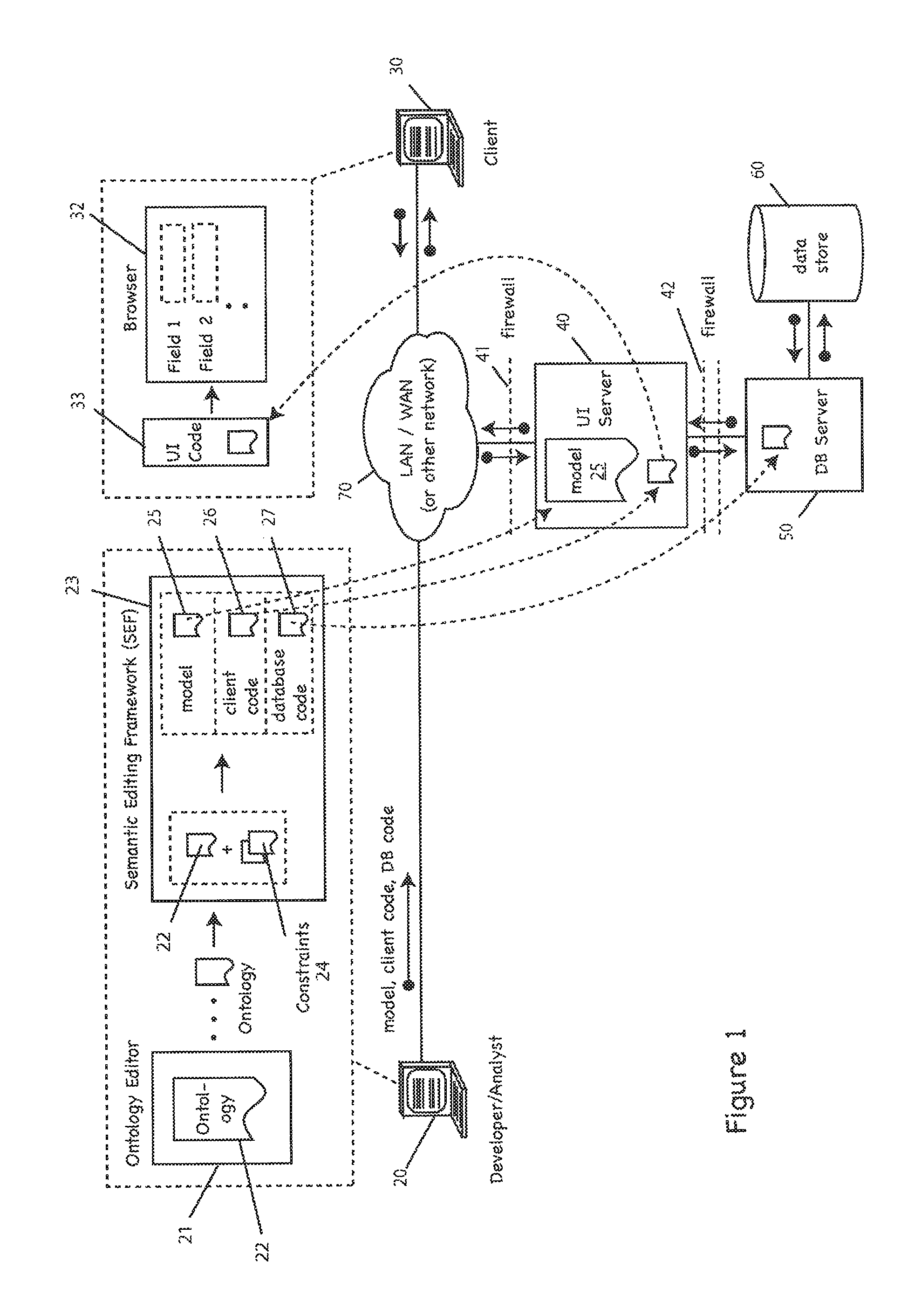
FIG. 1 depicts a digital data processing system and environment of the type used in practice of the invention;
FIGS. 2A-2E depict developer-side user interface (UI) displays, e.g., for defining a digital data storage and retrieval system that provides CRUD capabilities;
FIGS. 3A-3E depict client-side user interface (UI) displays, e.g., for performing CRUD or other digital data storage and retrieval operations; and
FIG. 4 depicts an operation of a system for storing and retrieving digital data (e.g., RDF data or otherwise) according to one practice of the invention.
DETAILED DESCRIPTION OF THE ILLUSTRATED EMBODIMENT
FIG. 1 depicts a digital data processing system and environment for storing and retrieving digital data (e.g., RDF or other semantic data) according to one practice of the invention. This can include, for example, creating, reading, updating and deleting (CRUD) data from a data store via a Graphical User Interface (GUI), or other User Interface (UI), e.g., command-line, etc. In the illustrated embodiment, the system includes digital data processors 20-50, which may be personal computers, workstations, mainframes, or other digital data processing apparatus of the type known in the art capable of executing applications, programs and/or processes. Although digital data processors 20-50 are shown here, those skilled in the art will appreciate that in other embodiments the system may include a greater or lesser number of such digital data processors.
Illustrated digital data processors 20-50 execute in a network environment. In other embodiments, digital data processors 20-50 may operate alone or in other environments, networked or otherwise. In any event, illustrated digital data processors 20-50 are coupled to each other, as shown, via a network 70, such as the Internet, a local-area network (LAN), wide-area network (WAN), or otherwise, that may be public, private, IP-based, etc.
In a typical embodiment, illustrated here, digital data processor 20 comprises a personal computer, workstation, mainframe, or other digital data processing apparatus, as discussed above, and is used by a developer or analyst (collectively, "analyst), to build, test, and deploy a software platform providing CRUD editing capabilities to a client 30, as discussed further below. The digital data processor 20 executes a variety of applications for creating such a platform, including, for example, an ontology editor 21 and a semantic editing framework (SEF) 23. The illustrated ontology editor 21 creates an ontology 22 (e.g., either automatically or via analyst input) that defines a structure of data (e.g., RDF data stored in data store 60, discussed below). This may include a text editor, an interpreter/compiler, libraries, or otherwise--all of the type known in the art, albeit as adapted in accord with the teachings hereof. In the illustrated embodiment, the editor 21 creates the ontology 22 with the Web Ontology Language (OWL), although in other embodiments the editor 21 may use other ontology-definition languages, as well.
The illustrated SEF 23 defines (e.g., via analyst input) user roles (e.g., Supervisor, Analyst, Administrator, etc.), security rules, validators, default values, field masking, and/or other constraints 24 (collectively, "constraints") that are applied to data characterized by the ontology 22. In the illustrated embodiment, the constraints 24 are defined in XML, although in other embodiments it may be otherwise. The SEF 23 generates a semantic model 25 (or simply, "model") by combining the ontology 22 and constraints 23 into a cohesive file (or set of files). Accordingly, in the illustrated embodiment, the model 25 is the "foundation" for providing CRUD capabilities to the client 30, as discussed further below. The SEF 23 also generates client code 26 (e.g., Adobe Flex) for creating the client interface 31, and the database code 27 which facilitates interaction between the digital data processor 50 (discussed below) and the data store 60 (discussed below).
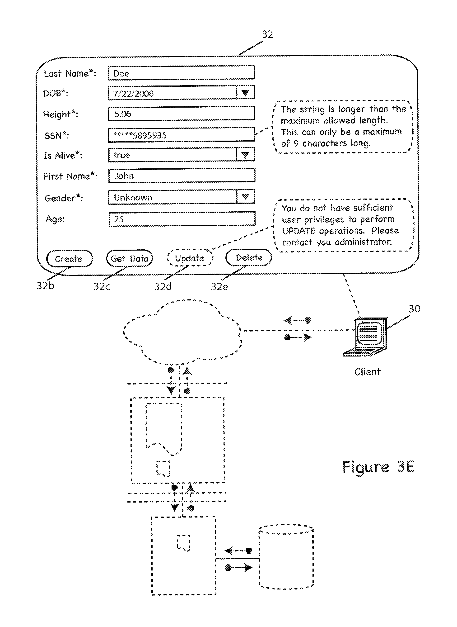
Illustrated digital data processor 30 comprises a personal computer, workstation, mainframe, or other digital data processing apparatus, as discussed above, and is used by a client to interface with stored data (e.g., RDF or otherwise). In the illustrated embodiment, the client 30 provides an interface 32 (e.g., graphical or otherwise) for interacting with data in the data store 60. By way of non-limiting example, the client 30 provides operations for creating, reading, updating and/or deleting data (CRUD) in the data store 60, although the client 30 may provide other operations, as well. In the illustrated embodiment, the interface 32 is generated from UI code 33 comprising the client code 26, HTML, and other web technologies known in the art, such as JavaScript, etc, although in other embodiments it may be otherwise.
The digital data processor 40 (or "UI server) comprises a personal computer, workstations, mainframe, server, or other digital data processing apparatus. In the illustrated embodiment, the digital data processor 40 generates the UI code 33 that displays the UI 32 on the client device 30. In the illustrated embodiment, the data processor 40 generates the code 33 from the model 25 and the client code 26, and comprises a combination of Adobe Flex code, and HTML, JavaScript, XML, etc., although it may also include other components instead of, or in addition to the aforementioned technologies (e.g., programming libraries, modules, etc.) Although in the illustrated embodiment, the data processor 40 generates the UI code 33, in other embodiments the data processor 20 may generate such code 33 itself, e.g., via the SEF 23, and the data processor 40 may only store and execute that code 33 without the model 25.
As discussed above, the digital data processor 40 executes in a network environment, e.g., in communications coupling with digital data processors 20-30 and 50 via the LAN/WAN 70. In the illustrated embodiment, the digital data processor 40 executes behind one or more firewalls 41 and 42 of the type conventionally known in the art of digital network security. The firewalls 41 and 42 themselves may comprise software executing on the digital data processor 40, or they may execute on dedicated appliances (e.g., one or more digital data processors). In any event, the firewalls 41 and 42 regulate traffic between and among the digital data processors 20-50, e.g., in order to prevent unauthorized access to the digital data processor 40. Thus, for example, the firewalls 41 and 42 may be configured by the analyst to permit, deny, encrypt, decrypt, or proxy network traffic between different security domains based upon a set of rules and/or other constraints (e.g., as defined in the model 25, or otherwise). Although firewalls are shown here, those skilled in the art will appreciate that systems according to the invention may employ a wide range of security measures of the type commonly known in the art of information security (e.g., physical security, authentication systems, anti-virus software, etc.), albeit as adapted in accord with the teachings hereof.
The illustrated digital data processor 50 (or "Database Server") comprises a personal computer, workstation, mainframe, server, or other digital data processing apparatus, that executes a digital data information storage and retrieval application (e.g., a database management system). The data processor 40 stores, retrieves, updates, deletes, and otherwise interfaces with data maintained on networked attached storage device 60. In the illustrated embodiment, the data store 60 comprises a hard disk drive and/or other persistent storage device of the type known in the art. By way of non-limiting example, the storage device (or "data store") 60 stores data (e.g., RDF or otherwise) for retrieval and display by the digital data processors 30 and 40.
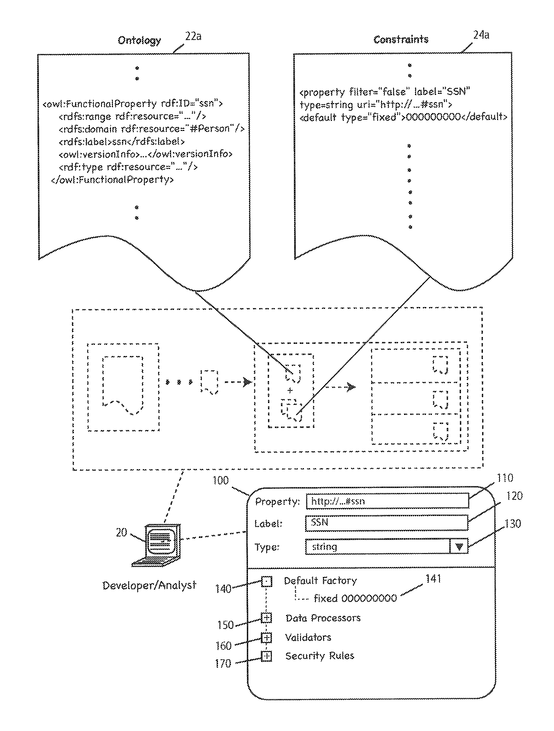
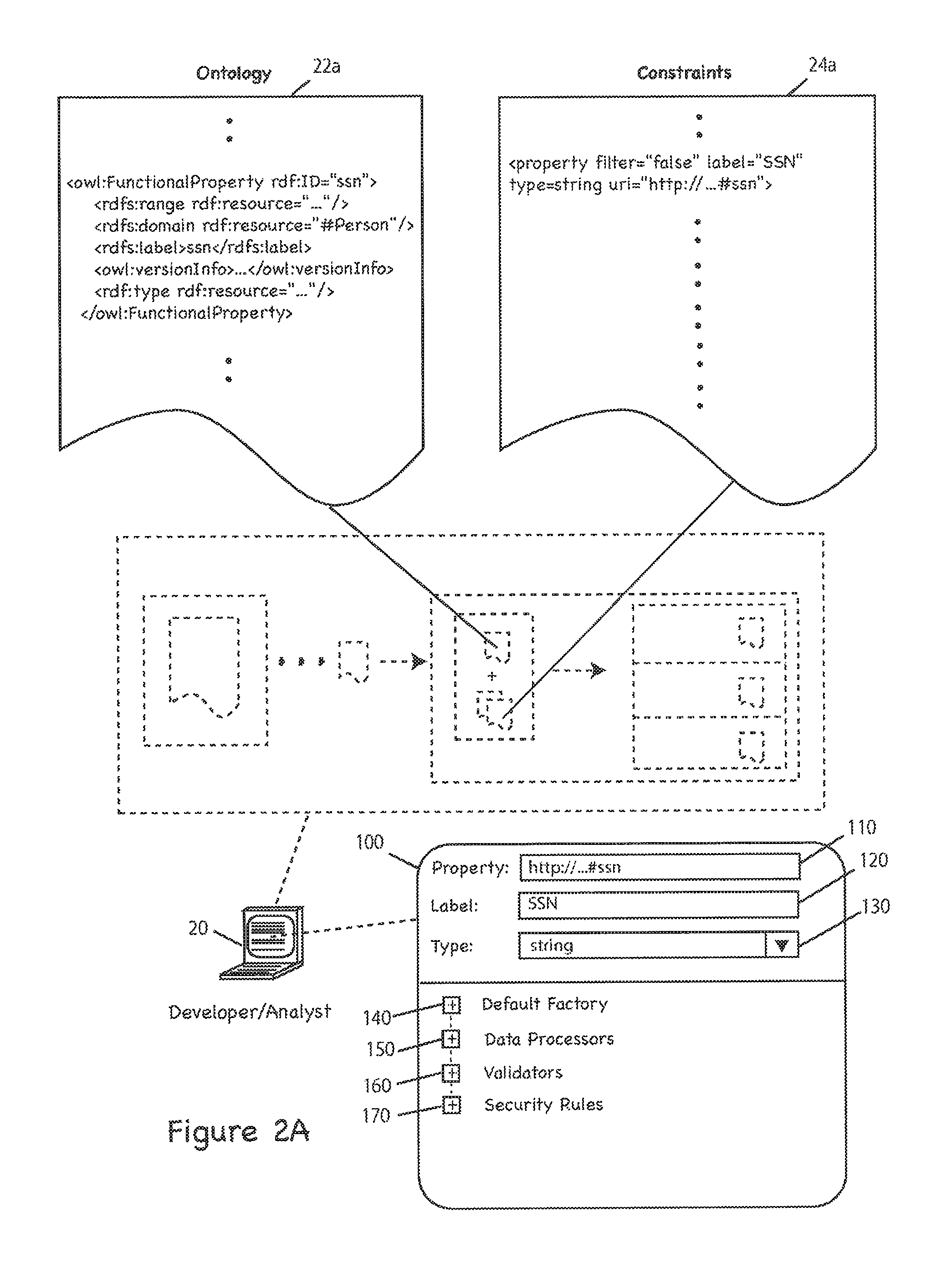
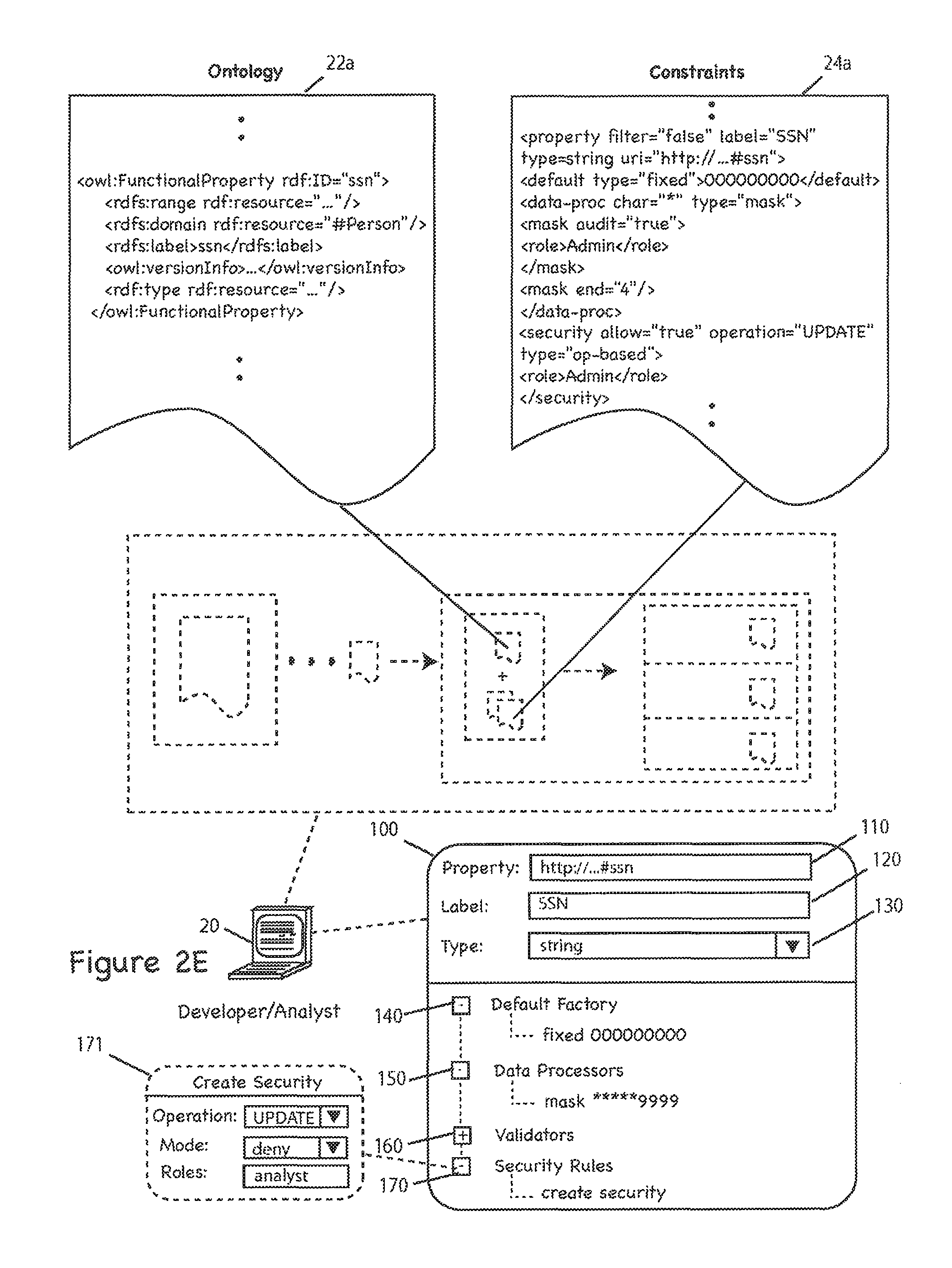
FIG. 2A-2E depict an exemplary user interface display 100 for the SEF 23 that allows a user (e.g., analyst, developer, administrator, etc.) to create, customize and associate the constraints 24 with the data characterized in the ontology 22. In the illustrated embodiment, the SEF 23 will generate the model 25, and the code associated therewith (e.g., client code 26, database code 27, etc.), from the ontology 22 and constraints 24. In other embodiments, a user may bypass the SEF display 100 altogether and manually code the constraints 24 to add or customize constraints as necessary. FIG. 2A-2E further depict exemplary code "snippets" 22a and 24a from the ontology 22 and constraints 24 which reflect a current display state of the UI 100. More particularly, as constraints are added, as illustrated in FIGS. 2A-2E, the constraints file 24a is updated to contain the SEF-generated code for those constraints. Associated FIGS. 3A-3E depict exemplary client user interface displays 32 corresponding to the SEF interface displays 100 of FIGS. 2A-2E. More specifically, FIG. 3A corresponds to FIG. 2A, FIG. 3B corresponds to FIG. 2B, and so on and so forth.
By way of overview, the ontology 22 is defined with OWL, as mentioned above, a portion of which is shown here (22a). OWL uses an RDF/XML syntax to define a set of "classes" (e.g., "Person") that each have assigned "properties" (e.g., "SSN"). However, those skilled in the art will appreciate that classes and properties are specific to an OWL implementation of the ontology 22, and in other embodiments, the ontology 22 may be implemented otherwise.
Also as discussed above, and again by way of overview, the constraints 24 are defined in XML, a portion of which is shown here (24a), although in other embodiments, the constraints may be defined otherwise. Those skilled in the art will appreciate that the ontology 22a, constraints 24a, and display 100 illustrated here are shown only by way of example, and other embodiments may be implemented otherwise (e.g., without properties or classes), or without ontologies at all (e.g., the system may use another semantic definition structure).
FIG. 2A, more particularly, depicts an exemplary SEF 23 user interface 100 displayed on the digital data processor 20 used for customizing and generating the model 25. In the illustrated embodiment, shown here, an analyst may add, remove, update, or otherwise define constraints via a set of graphical menus 110-170, and the SEF 23 generates code 24a corresponding to those constraints. As discussed above, and below, those constraints can include, for example, default values 140, field masking 150, validators 160, and security rules 170, just to name a few. Those skilled in the art will appreciate that menus 110-170, as well as the code 22a and 24a, are shown merely by way of example, and in practice of the invention, the system may include many different configuration options (e.g., pre-defined in the system package, defined by a developer during the initial system deployment, and/or by a client after the system has been deployed).
Although not illustrated here, the SEF 23 may also define user roles (e.g., Supervisor, Analyst, etc.), and assign each role a selected "privilege" level. By way of non-limiting example, a Supervisor may have a higher privilege level than an Analyst. In the illustrated embodiment, user roles are often associated with constraints (e.g., security rules, field masking, etc.), as discussed further below. Thus, by way of non-limiting example, the SEF 23 may define a constraint that allows a Supervisor, but not an Analyst, to perform update operations.
As shown here, by way of example, the display 100 is divided into two regions (i.e., a top region and a bottom region). The top region includes a property field 110, label field 120, and type field 130. Those skilled in the art will appreciate that the illustrated display 100 is shown merely by way of example, and other embodiments may use a different display (e.g., an undivided display, a display with three or more regions, etc.), or no display at all (e.g., an analyst may edit the model directly by hand-coding the constraints 22).
In the illustrated embodiment, the property field 110 displays the namespace and name of the selected property (e.g., "http:// . . . /#ssn," as shown by way of non-limiting example) defined in the constraints 22a (e.g., via an analyst using the SEF UI 100). The label field 120 comprises a configurable field used to set the field name (e.g., "SSN," as shown by way of non-limiting example) that will display on the client interface 32. The type field 130 is a configurable field (e.g., via a "drop down" selection box, as shown) that sets the data type of the field, e.g., "string" (as shown by way of non-limiting example), boolean, data, or float, just to name a few. In the illustrated embodiment the type field 130 is typically populated from the ontology 22, but it may also be manually set, e.g., by the analyst. Those skilled in the art will appreciate that fields 100-130 are shown by way of example, and in practice may include other fields, selection boxes, checkboxes and otherwise, e.g., as specified by the ontology 22, constraints 24, or otherwise.
The bottom region of display 100 provides configuration menus for defining the constraints 24. The display 100 includes a default factory menu 140, data processor menu 150, validator menu 160, and security rules menu 170, although in practice of the invention, a greater or lesser number of menus may be displayed. As shown in FIG. 2B, by way of non-limiting example, the user has chosen to constrain the property "http:// . . . #ssn" having the label "SSN" as having a "string" value. Also as shown, the SEF 23 has generated the corresponding code 24 for that constraint. Again, the display 100 and constraint code 24a are shown by way of non-limiting example and may vary in practice (e.g., the generated code may be in a markup language other than XML, etc.).
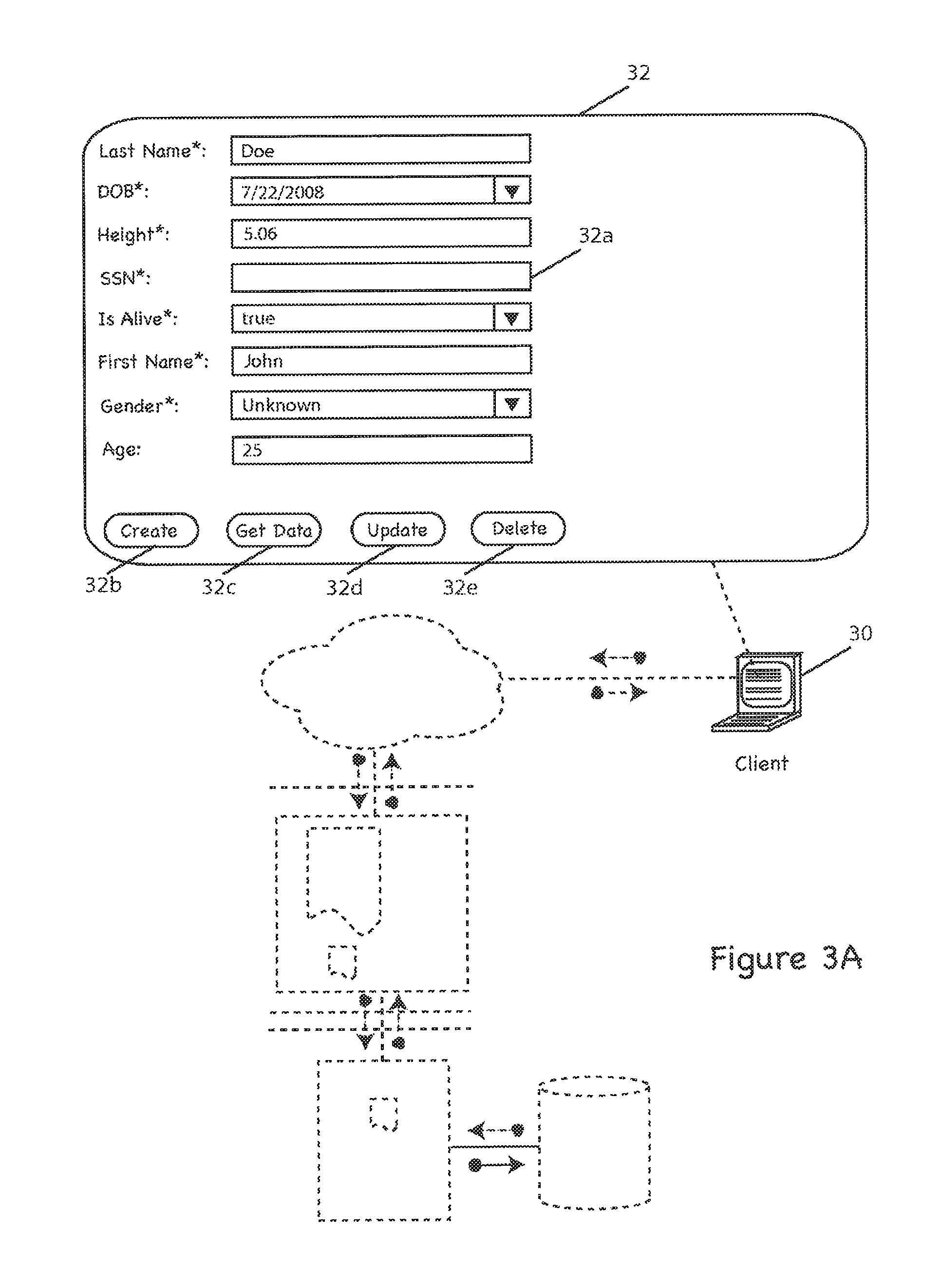
FIG. 2B depicts the display 100, generally as described above, further including a default factory constraint 141 defined in the default factory menu 140. The default factory constraint 141 effectively sets a static default value for a selected property (e.g., "http:// . . . #ssn"). More specifically, the constraint 141 specifies that the selected property has a fixed default value, e.g., "000000000." The SEF 23 will subsequently generate the code 24a that will instruct the client 30 to display a default value of "000000000" for this property in the corresponding field 32a of the UI 32. See FIG. 3B. Those skilled in the art will appreciate that in practice of the invention, other default values may be defined instead of, or in addition to, the illustrated default value, shown by way of non-limiting example.
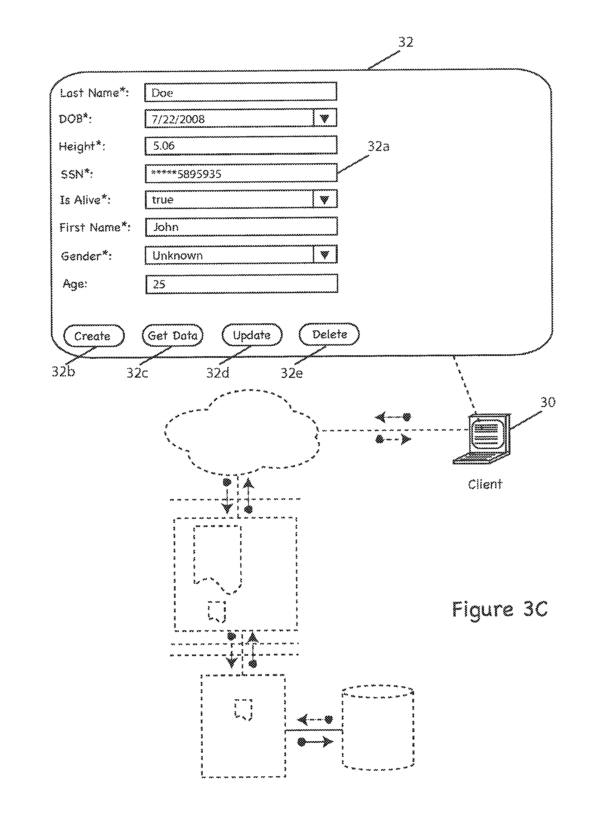
FIG. 2C depicts the display 100, generally as described above, further including a data processor 151 defined in the data processor menu 150. The specified data processor 151 applies a character masking constraint to the selected property (e.g., "http:// . . . #ssn"). In the illustrated embodiment, selecting "mask" instructs the SEF 23 to generate code that, when executed by the digital data processor 40 (or other apparatus that generates the UI 32), will hide the property's value in the UI 32 and enter a mask character that will display in the UI (e.g., an asterisk). See FIG. 3C. Properties can be assigned a number of different masking settings that will be applied based upon the role assigned to the user viewing the field. By way of non-limiting example, a data processor could be defined to allow a "supervisor" to see more of data (e.g., a social security number) than an "analyst," or to mask additional characters when performing an specific operations.
Generally, masking is performed by entering into the UI 100 the number of characters that should be masked at the start and end of the selected field, and by selecting the role(s) that the mask should apply to. In the illustrated embodiment, a blank start and/or end values are assumed as zeroes, and a blank role entry will apply the mask to all roles, although in other embodiments it may be otherwise. Moreover, if a user's role matches multiple entries in the list of masks for a selected property, then the first mask in the list will be applied. In the illustrated embodiment, masking is based on the role of the user, and that the system will always mask according to the most restrictive role added, although in other embodiments this may vary.
Those skilled in the art will appreciate that in practice of the invention, other data processors may be defined instead of, or in addition to, the illustrated masking data processor, shown by way of non-limiting example.
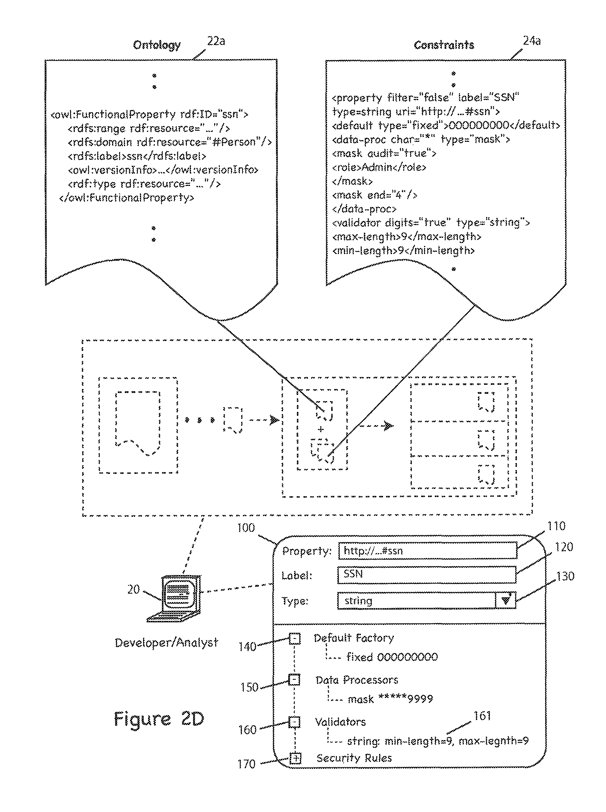
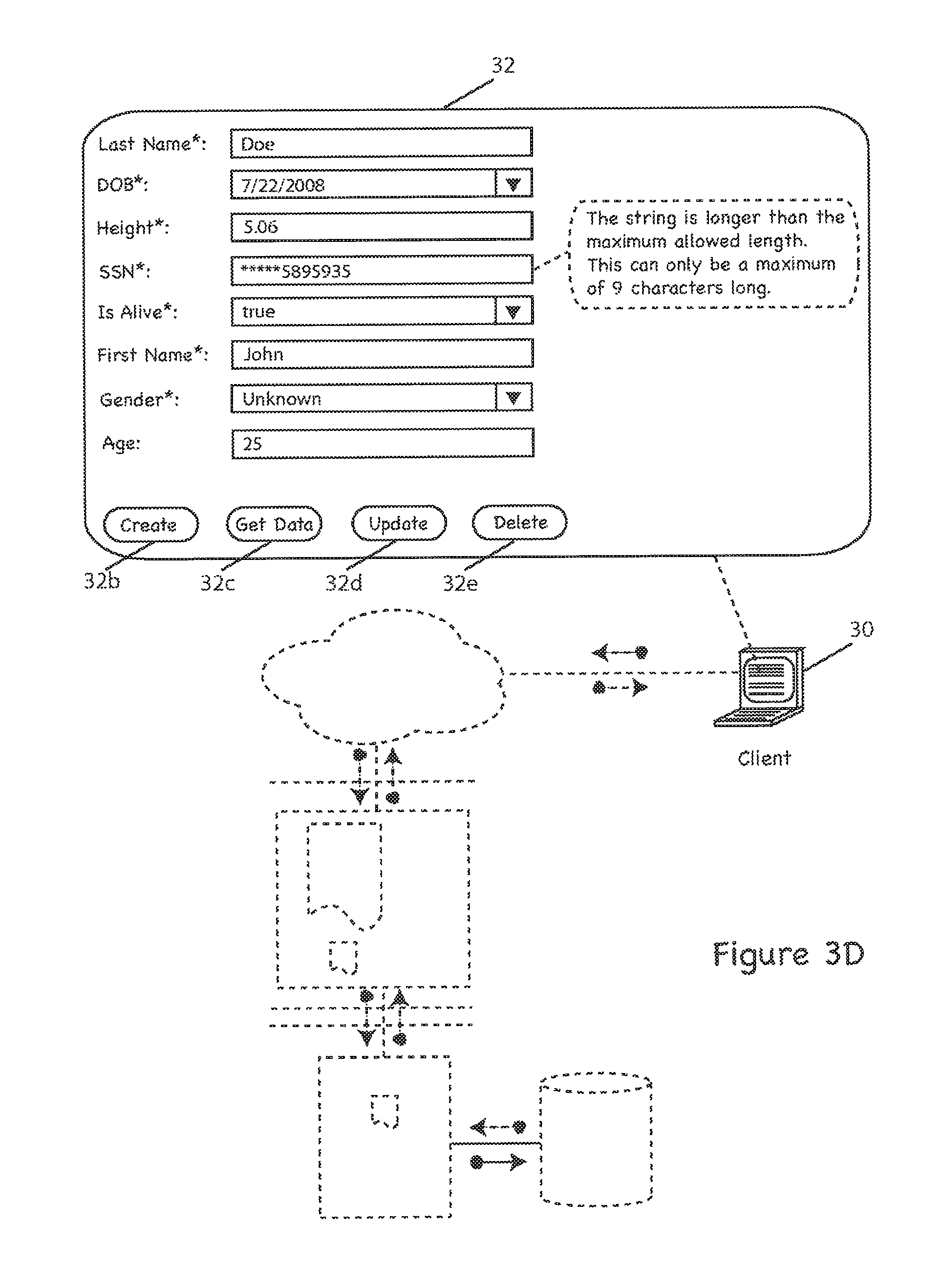
FIG. 2D depicts the display 100, generally as described above, further including a validator constraint 161 defined in the validator menu 160. In the illustrated embodiment, the constraint 161 allows a user to create an integer definition for validation that can be set with minimum or maximum values for a selected property. Thus, as shown by way of non-limiting example, the selected property (e.g., social security number) must have a minimum length of nine characters and maximum length of nine characters, i.e., effectively requiring a nine-digit entry. By way of further example, the SEF 23 will generate code 24a that, when executed by the digital data processor 40, will instruct the client 30 to display a UI 32 that requires a nine-digit entry in the selected property field 32a. See FIG. 3D. Those skilled in the art will appreciate that in practice of the invention, other validators may be defined instead of, or in addition to, the illustrated validator, shown by way of non-limiting example.
FIG. 2E depicts the display 100, generally as described above, further including a security rule constraint defined in the security rules menu 170. In the illustrated embodiment, a security rule can be set by user role and/or by operation (e.g., create, read, update, delete, etc.). As shown, by way of non-limiting example, a user can define a constraint (e.g., via pop-window 171 or otherwise) that specifies that Analysts are not allowed to perform update operations. By way of further example, the SEF 23 will generate code 24a that, when executed by the digital data processor 40, will instruct the client 30 to display a UI 32 that will not allow Analysts to perform update operations. See FIG. 3E. Those skilled in the art will appreciate that in practice of the invention, other security rules may be defined instead of, or in addition to, the illustrated security rule, shown by way of non-limiting example.
FIGS. 3A-3E, referenced above, depict a user interface (UI) 32 executing on client digital data processing device 30 (e.g., personal computer, workstation, etc.). In the illustrated embodiment, the client device 30 provides a user interface 32 for interacting with stored digital data (e.g., data create, read, update and delete operations, and so forth). As shown, the user interface 32 includes a variety of fields, e.g., "SSN" field 32a, discussed above, and several "buttons" 32b-32e for performing "CRUD" operations (e.g., via HTTP methods, RPC, or otherwise). Although user interface buttons are only included for data create 32b, read 32c, update 23d and delete 32e operations, those skilled in the art will appreciate that in practice of the invention the UI 32 may include other interface options instead of, or in addition to, the interface buttons shown here by way of non-limiting example.
FIG. 4 depicts an exemplary operation of a system for storing and retrieving digital data (e.g., RDF or other semantic data) according to one practice of the invention. The illustrated sequence of steps is just one of many with which the invention may be practiced. Thus, it may be practiced with a greater or lesser number of steps than those shown here, ordered as shown in the drawing or otherwise.
By way of overview, as discussed above, a system executing in accord herewith stores and retrieves digital data (e.g., RDF or other semantic data) in accord with a model 25, or, more particularly, in accord with an ontology 21 (e.g., defined via the ontology editor 21) and a set of constraints 24 (e.g., defined via the SEF 23). This storing and retrieving of digital data can include, for example, creating, reading, updating and deleting (CRUD) data from a data store 60 via a Graphical User Interface (GUI) 32, or other User Interface (UI), e.g., command-line, etc.
Unlike other data storage and retrieval systems currently available in the prior art (e.g., in which developers APIs supplied with the systems to write "one-off" applications), the system of the illustrated embodiment allows a user 20 (e.g., developer, analyst, etc.) to create a model 25 that defines how user's (e.g., client 30) interact with data (e.g., RDF data in data store 60). Thus, for example, as client requirements change (e.g., increased security on UPDATE operations), the user may easily edit the model 25, rather than having the original developers either extensively modify the existing application, or write an entirely new application from scratch.
FIG. 4 depicts a sequence of steps for performing storage and retrieval operations (e.g., CRUD operations, etc.) in a system according to the invention. In steps 400-430, a developer, administrator, analyst, etc. (collectively, "analyst") builds and deploys a software platform providing CRUD editing capabilities to a client, as discussed above. More particularly, in the illustrated embodiment, an analyst executes the ontology editor 21 (e.g., on the digital data processor 20 or otherwise). See step 400. The illustrated ontology editor 21 creates an ontology 22 that defines a structure of data (e.g., RDF data stored in data store 60, discussed below). This may include a text editor, an interpreter/compiler, libraries, or otherwise--all of the type known in the art, albeit as adapted in accord with the teachings hereof. In the illustrated embodiment, the editor 21 creates the ontology 22 with the Web Ontology Language (OWL), although in other embodiments the editor 21 may use other ontology-definition languages, as well.
In step 410, the analyst executes the SEF 23 (e.g., on the digital data processor 20, or otherwise) to define user roles (e.g., Supervisor, Analyst, Administrator, etc.), security rules, validators, default values, field masking, and/or other constraints 24 (collectively, "constraints") that are applied to data characterized by the ontology 22. In the illustrated embodiment, the constraints 24 are defined in XML, although in other embodiments it may be otherwise. The SEF 23 generates a semantic model 25 (or simply, "model") by combining the ontology 22 and constraints 23 into a cohesive file (or set of files). Accordingly, in the illustrated embodiment, the model 25 is the "foundation" for providing CRUD capabilities to the client 30.
In step 420, the SEF 23 generates and transmits database code 27 to the database server 50. In the illustrated embodiment, the code 27 facilitates interaction between the database server 50 and the data store 60. In step 430, the SEF 23 generates and transmits the client code 26 (e.g., Adobe Flex) to the UI Server 40 for creating the client interface 31 displayed on the client device 30 (e.g., via a web browser), although in other embodiments, the code 26 may be transmitted directly to client device 30.
In the illustrated embodiment, as discussed above, the SEF 23 displays a user interface 100 for the analyst to customize and generate the model 25. More particularly, the analyst may add, remove, update, or otherwise define the constraints 24 via a set of graphical menus 110-170, and the SEF 23 generates code 24a corresponding to those constraints. As discussed above, those constraints 24 can include, for example, default values 140, field masking 150, validators 160, and security rules 170, just to name a few.
In step 440, the client device 30 sends a request to the UI server 40 for an interface 32 (e.g., a web page) for interacting with data in the data store 60. By way of non-limiting example, the client 30 may request a web page that provides form-Tillable fields and graphical buttons for performing CRUD operations, although the client 30 may request other interfaces, as well (e.g., a log-in screen, etc.). In the illustrated embodiment, the interface 32 is generated from UI code 33 comprising the client code 26, HTML, and other web technologies known in the art, such as JavaScript, etc, although in other embodiments it may be otherwise.
In step 450, the UI server 40 generates the UI code 33 that will display the UI 32 requested in step 440. In the illustrated embodiment, the UI server 40 generates the code 33 from the model 25 and the client code 26, and comprises a combination of Adobe Flex code, HTML, JavaScript, XML, etc., although it may also include other components instead of, or in addition to, the aforementioned technologies (e.g., programming libraries, modules, etc.). Although in the illustrated embodiment, the UI server 40 generates the UI code 33, in other embodiments the data processor 20 may generate such code 33 itself, e.g., via the SEF 23, and the UI server 40 may only store and execute that code 33.
In step 460, the UI server 40 sends the UI code 33 to the client 30 (e.g., via LAN/WAN 70), and the client 30 renders the user interface 32 (e.g., a web-fillable form with blank data fields) from that code 33. Those skilled in the art will appreciate that one or more firewalls 41 are employed to insure that the UI code 33, or other data, is not intercepted (e.g., by hackers, sniffers, etc.). Moreover, to further insure system security and integrity, in the illustrated embodiment only necessary code and data is sent to the client, e.g., as defined by the model 25, discussed above. Although not shown here, in other embodiments, the system may employ additional firewalls or other security measures commonly known in the art of information security, albeit as adapted in accord with the teaching hereof.
In step 470, the client sends a data identifier (e.g., a record identifier) to the UI server 40 for processing by the UI server 40 and/or database server 50, as discussed below. By way of non-limiting example, the data identifier may be a "Customer ID" that has data attributes (e.g., last name, date of birth, height, social security number, etc.) associated with fields of the interface 32. In step 480, the UI server 40 sends a transaction request to the database server 50 to retrieve data associated with the identifier from the data store 60. In step 490, the database server 50 processes the request of step 480 and retrieves the data from the store 60 (e.g., via SQL, SPARQL, etc.). In steps 500-510, the retrieved data is sent to the UI server 40 and then to the client 30 for display in the UI 32. See, for example, FIG. 2A.
In step 520, the client 30 inputs data and initiates a selected CRUD operation (e.g., via the user interface 32). For the purposes of this discussion, we will assume that the interface 32 looks similar to that illustrated in FIGS. 2A-2E, and the user wishes to input a social security number data value into a social security number data fields (i.e., perform a data create operation). However, those skilled in the art will again appreciate that these steps are shown merely by way of non-limiting example, and may include other steps in addition to, or instead of, the steps discussed above (e.g., other CRUD operations may be performed, other data values may be input/edited, etc.).
In step 530, the client 30 performs a "client-side" validation on the data inputted in step 520. In the illustrated embodiment, client-side validations are executed by the UI code 33, and are defined in the client code 26, although in other embodiments they may be executed and/or defined otherwise (e.g., in the model 25). By way of non-limiting example, client-side validations can include, among others, the constraints discussed above (e.g., minimum string length, maximum string length, etc.), and if any validation fails, the user is warned, e.g., via a pop-up window displayed in the UI 32 or otherwise. Thus, for example, if the client code 26 required a validation that a social security number data value must have a minimum and maximum character length of nine characters, and the user failed to input a nine-character social security number data value, the user would be warned (see, e.g., FIG. 3D), and prompted to reenter the number. This process will be repeated until all validations are passed. Those skilled in the art will appreciate the above example is just that--an example, and in practice of the invention other validations may be performed in addition to, or instead of, the validation described above.
In step 540, the inputted data (e.g., the social security number in this example), is sent to the UI server 40 (e.g., via LAN/WAN 70) for "server-side" validations (step 550). As discussed above, these validations are defined in the model 25 and executed by code generated therefrom by the UI server 40. They can include, for example, a check to insure that the social security number is a string containing exactly nine digits (e.g., in the event that such an error was not caught by the client-side validations in step 530). By way of further example, if the inputted data does fail this validation, or any other validations (e.g., as defined by the model 25 or otherwise), the UI server 40 may generate a server-side exception which can, for example, terminate the current transaction, or it can be sent to the client 30 in the form of a graphical warning (see step 560).
In step 560, a warning is sent from the UI server 40 to the client 30 if an exception (or other type of error) is thrown or detected in the validation step 550. By way of non-limiting example, such an error can be generated as a result of an inputted social security number that is not exactly nine digits in length (e.g., as described above in step 530), or as otherwise required by the model 25. In the illustrated embodiment, the warning can be a pop-up window (e.g., of the type shown in FIG. 3D), etc. In step 570, the client can re-input data (e.g., a new social security number data value) that will be re-validated in step 580 (e.g., as described above in step 550). This process will be repeated until the validation step 580 is successfully completed (i.e., without any detected exceptions or errors).
In step 590, the validated data (e.g., the new social security number data value) is sent to the database server 50 for processing (e.g., via a LAN/WAN connection, cabled connection, etc.). In step 600, the database server 50 processes the transaction, e.g., associates the inputted data value with the social security number attribute of the data identifier (e.g., Customer ID "555555") in the data store 60. This can be accomplished by a variety of techniques pursuant to the data format of the store 60. Thus, for example, SPARQL may be used for an RDF data store, SQL for a relational database, and so forth. In this example, the code (whether SPARQL, SQL, etc.) for associating the inputted data value with the social security number attribute of the specified data identifier (e.g., Customer ID "555555") comprises the code 27 generated by the SEF 23 (as discussed above and shown in FIG. 1) and stored/executed on the database 50, (as discussed above and shown in FIG. 1), although in other embodiments it may be otherwise.
In step 610, the database server 50 returns the result of the processed transaction (e.g., completed, failed, etc.) and the processed data (e.g., a confirmed created data value, a confirmed updated data value, etc.) to the UI server 50. In the illustrated embodiment, failed transactions generate a warning by the database server 50 or UI server 40 (e.g., as described in step 560) that can be sent to the client 30, administrator, other user, etc.
In step 620, the data (e.g., social security number) is sent to the client 30 for display in the UI 32, subject to any constraints defined by the model 25. Thus, as shown here by way of non-limiting example, a masking constraint may be applied to the social security number data value before it is sent to the client 30 for display in the UI 32. In the illustrated embodiment, masking will hide a selected portion of the data value (or the entire data value) on the UI server 40 (i.e., "server-side" masking), and the full data value (e.g., social security number) will never be sent to the client 30 or be displayed in the UI 32. Rather, the UI server 40 will replace selected portions (e.g., one or more characters) of the data value with mask values for display in the UI 32 (e.g., an asterisk for each of the masked characters in the data value). See, e.g., FIG. 3C. Of course, those skilled in the art will appreciate that other types of masking may be applied in this step, as well as other constraints in addition to, or instead of, masking constraints.
Described above are methods and apparatus meeting the desired objectives. Those skilled in the art will appreciate that the embodiments herein are merely examples of the invention and that other embodiments incorporating changes therein fall within the scope of the invention, of which we claim:
* * * * *
References
-
cdc.gov/nedss/About/overview.html
-
-
swordfish.rdfweb.org/rdfquery
-
orionhealth.com/maestro_overview.htm
-
-
guha.com/rdfdb/query.html
-
hpl.hp.com/semweb/rdql.htm
-
herzberg.ca.sandia.gov/jess/docs/52/rete.html
-
-
astho.org/?template=public_health_info_network.html
-
planetrdf.com/guide
-
w3.org/1999/06/07-WebData
-
-
infomesh.net/2001/enriquire/manual
-
cs.tut.fi/.about.jkorpela/rfc/2396/full.html
-
-
-
ilrt.bris.ac.uk/discovery/2000/111/QL/QL.txt
-
mozill.org/rdf/doc/api.html
-
-
-
dublincore.org
-
-
-
-
-
-
-
-
www-db.stanford.edu/.about.melnik/rdf/db.html
-
-
-
w3.org.TR/1999/REC-rdf-syntax-19990222
-
-
infolab.stanfordedu/.about.stefan/daml/order.html
-
-
-
comp.glam.ac.uk/people/staff/dstudhope
-
-
ilrt.org/discovery/2000/10/swsql
D00000
D00001
D00002
D00003
D00004
D00005
D00006
D00007
D00008
D00009
D00010
D00011
D00012
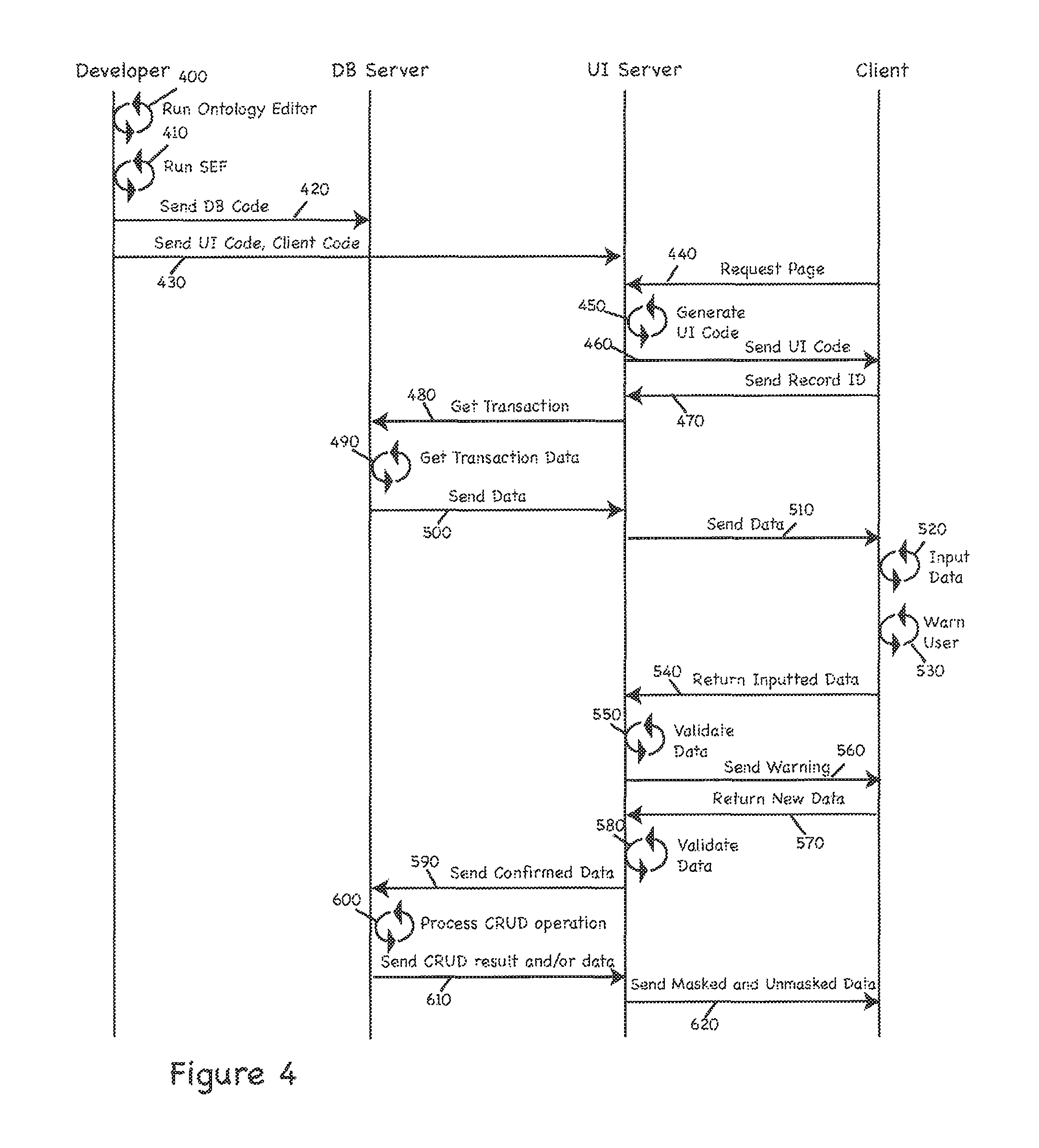
XML
uspto.report is an independent third-party trademark research tool that is not affiliated, endorsed, or sponsored by the United States Patent and Trademark Office (USPTO) or any other governmental organization. The information provided by uspto.report is based on publicly available data at the time of writing and is intended for informational purposes only.
While we strive to provide accurate and up-to-date information, we do not guarantee the accuracy, completeness, reliability, or suitability of the information displayed on this site. The use of this site is at your own risk. Any reliance you place on such information is therefore strictly at your own risk.
All official trademark data, including owner information, should be verified by visiting the official USPTO website at www.uspto.gov. This site is not intended to replace professional legal advice and should not be used as a substitute for consulting with a legal professional who is knowledgeable about trademark law.