Holder and mobile terminal
Yang , et al. Nov
U.S. patent number 10,481,654 [Application Number 15/878,017] was granted by the patent office on 2019-11-19 for holder and mobile terminal. This patent grant is currently assigned to Huawei Device Co., Ltd.. The grantee listed for this patent is Huawei Device Co., Ltd.. Invention is credited to Linfang Jin, Hualin Li, Wenbing Tang, Xiangyang Yang, Jie Zou.


| United States Patent | 10,481,654 |
| Yang , et al. | November 19, 2019 |
Holder and mobile terminal
Abstract
A holder and a mobile terminal including the holder are disclosed. The holder is located in the mobile terminal, the holder includes a heat conduction area and a heat insulation area, the heat insulation area is close to an edge of the holder, the heat insulation area is adjacent to the heat conduction area, and a heat emitting element in the mobile terminal is proximate to the heat conduction area. The heat insulation area is provided on the holder, and the heat insulation area is close to the edge of the holder and is adjacent to the heat conduction area, so that, in a process of transferring heat in the heat conduction area to the edge of the holder, the heat is impeded by the heat insulation area, thereby reducing heat at the edge of the holder.
| Inventors: | Yang; Xiangyang (Shanghai, CN), Jin; Linfang (Shenzhen, CN), Li; Hualin (Shanghai, CN), Tang; Wenbing (Shenzhen, CN), Zou; Jie (Shenzhen, CN) | ||||||||||
|---|---|---|---|---|---|---|---|---|---|---|---|
| Applicant: |
|
||||||||||
| Assignee: | Huawei Device Co., Ltd.
(Dongguan, CN) |
||||||||||
| Family ID: | 54143701 | ||||||||||
| Appl. No.: | 15/878,017 | ||||||||||
| Filed: | January 23, 2018 |
Prior Publication Data
| Document Identifier | Publication Date | |
|---|---|---|
| US 20180150115 A1 | May 31, 2018 | |
Related U.S. Patent Documents
| Application Number | Filing Date | Patent Number | Issue Date | ||
|---|---|---|---|---|---|
| 15127705 | 9910468 | ||||
| PCT/CN2014/073815 | Mar 21, 2014 | ||||
| Current U.S. Class: | 1/1 |
| Current CPC Class: | G06F 1/1626 (20130101); H05K 9/0024 (20130101); H05K 7/2039 (20130101); G06F 1/203 (20130101); H05K 1/0203 (20130101) |
| Current International Class: | G06F 1/20 (20060101); H05K 1/02 (20060101); G06F 1/16 (20060101); H05K 7/20 (20060101); H05K 9/00 (20060101) |
References Cited [Referenced By]
U.S. Patent Documents
| 5581443 | December 1996 | Nakamura et al. |
| 6266941 | July 2001 | Nishimoto |
| 6333847 | December 2001 | Katsui et al. |
| 6414844 | July 2002 | Shimada et al. |
| 6545866 | April 2003 | Katsui et al. |
| 6570086 | May 2003 | Shimoji et al. |
| 6859364 | February 2005 | Yuasa et al. |
| 6938968 | September 2005 | Tanimoto et al. |
| 7188484 | March 2007 | Kim |
| 7412846 | August 2008 | Sekiya et al. |
| 7486517 | February 2009 | Aapro et al. |
| 7603205 | October 2009 | Barry et al. |
| 7833605 | November 2010 | Tenra et al. |
| 8673471 | March 2014 | Yokoyama |
| 8753471 | June 2014 | Yamada et al. |
| 8790477 | July 2014 | Tenra et al. |
| 9049801 | June 2015 | Rothkopf et al. |
| 9578791 | February 2017 | Shen |
| 9690341 | June 2017 | Shen |
| 9729207 | August 2017 | Hwang et al. |
| 10019046 | July 2018 | Shen |
| 10194521 | January 2019 | Kim |
| 2003/0161132 | August 2003 | Shimoji et al. |
| 2004/0244397 | December 2004 | Kim |
| 2006/0126304 | June 2006 | Smalc et al. |
| 2010/0072952 | March 2010 | Nakajima et al. |
| 2011/0064983 | March 2011 | Yokoyama et al. |
| 2012/0206882 | August 2012 | Mohammed et al. |
| 2013/0141870 | June 2013 | Rothkopf et al. |
| 2013/0301221 | November 2013 | Wu |
| 2014/0102678 | April 2014 | Zou |
| 2014/0355194 | December 2014 | Shiraishi et al. |
| 2014/0369000 | December 2014 | Kim et al. |
| 2017/0055367 | February 2017 | Shen |
| 1373982 | Oct 2002 | CN | |||
| 100407097 | Jul 2008 | CN | |||
| 201114231 | Sep 2008 | CN | |||
| 201115242 | Sep 2008 | CN | |||
| 201550395 | Aug 2010 | CN | |||
| 102017228 | Apr 2011 | CN | |||
| 202003615 | Oct 2011 | CN | |||
| 102438423 | May 2012 | CN | |||
| 202335181 | Jul 2012 | CN | |||
| 102711416 | Oct 2012 | CN | |||
| 103151318 | Jun 2013 | CN | |||
| 103209574 | Jul 2013 | CN | |||
| 203086894 | Jul 2013 | CN | |||
| 103348782 | Oct 2013 | CN | |||
| 203327471 | Dec 2013 | CN | |||
| 102011117490 | May 2013 | DE | |||
| 1233666 | Aug 2002 | EP | |||
| 2075993 | Jul 2009 | EP | |||
| H03003741 | Jan 1991 | JP | |||
| H11143584 | May 1999 | JP | |||
| 201142575 | May 2001 | JP | |||
| 2001308137 | Nov 2001 | JP | |||
| 2003188323 | Jul 2003 | JP | |||
| 3601282 | Dec 2004 | JP | |||
| 2005277163 | Oct 2005 | JP | |||
| 2006165154 | Jun 2006 | JP | |||
| 3810734 | Aug 2006 | JP | |||
| 2007019512 | Jan 2007 | JP | |||
| 2008131512 | Jun 2008 | JP | |||
| 2010165728 | Jul 2010 | JP | |||
| 2010251386 | Nov 2010 | JP | |||
| 2011119474 | Jun 2011 | JP | |||
| 2012048250 | Mar 2012 | JP | |||
| 2013150067 | Aug 2013 | JP | |||
| 2013214868 | Oct 2013 | JP | |||
| 2014517538 | Jul 2014 | JP | |||
| 2010032484 | Mar 2010 | WO | |||
| 2013018553 | Feb 2013 | WO | |||
| 2013108311 | Jul 2013 | WO | |||
| 2013108312 | Jul 2013 | WO | |||
| 2013191493 | Dec 2013 | WO | |||
Other References
|
"Service Manual for L1 and L2, Nokia Lumia 820 RM-824, RM-825 Version 1.0," Nokia Care Academy, pp. 1-31 (2012). cited by applicant . Yao, "High-Frequency Proximity Heating for Injection Molding Applications," Polymer Engineering and Science-2006, Wiley InterScience, pp. 938-945 (2006). cited by applicant. |
Primary Examiner: Hoffberg; Robert J
Attorney, Agent or Firm: Leydig, Voit & Mayer, Ltd.
Parent Case Text
CROSS REFERENCE TO RELATED APPLICATIONS
This application is a continuation of U.S. patent application Ser. No. 15/127,705, filed on Sep. 20, 2016, which is a National Stage of International Application No. PCT/CN2014/073815 filed on Mar. 21, 2014. The afore-mentioned patent applications are hereby incorporated by reference in their entireties.
Claims
What is claimed is:
1. A mobile terminal, comprising: a holder; a side frame; a display screen; and a heat emitting element disposed on a circuit board; wherein the holder is a display screen holder which is located between the display screen and the circuit board, the side frame surrounds the holder, the holder comprises a heat conduction area and a heat insulation area, the heat insulation area is provided between the heat conduction area and an edge of the holder, and the heat conduction area is made of metal; and wherein the heat conduction area is provided to transfer heat generated by the heat emitting element, and, in a process of transferring the heat in the heat conduction area to the side frame, the heat insulation area is provided to impede the heat.
2. The mobile terminal according to claim 1, wherein the heat insulation area is provided close to a long edge of the side frame.
3. The mobile terminal according to claim 1, wherein the heat insulation area is provided with a heat insulation cavity with air.
4. The mobile terminal according to claim 3, wherein the heat insulation cavity is at least one strip-shaped hole.
5. The mobile terminal according to claim 4, wherein the mobile terminal further comprises a shielding cover, the shielding cover surrounds the heat emitting element on the circuit board.
6. The mobile terminal according to claim 5, wherein the heat emitting element is a chip.
7. The mobile terminal according to claim 1, wherein the heat insulation area is made of a low heat conduction material, the low heat conduction material has a heat conductivity coefficient range of 0-0.026 W/m-K.
8. The mobile terminal according to claim 1, wherein the mobile terminal further comprises a shielding cover, the shielding cover surrounds the heat emitting element on the circuit board.
9. The mobile terminal according to claim 8, wherein a heat conduction medium is provided between the shielding cover and the heat emitting element.
10. The mobile terminal according to claim 1, wherein a material of the holder is a heat conduction material.
11. The mobile terminal according to claim 1, wherein the heat emitting element is a chip.
12. The mobile terminal according to claim 1, wherein the mobile terminal is a mobile phone.
13. The mobile terminal according to claim 1, wherein the heat insulation area isolates the heat emitting element from the side frame.
Description
TECHNICAL FIELD
The present disclosure relates to electronic devices in the communications field, and in particular, to a holder and a mobile terminal having the holder.
BACKGROUND
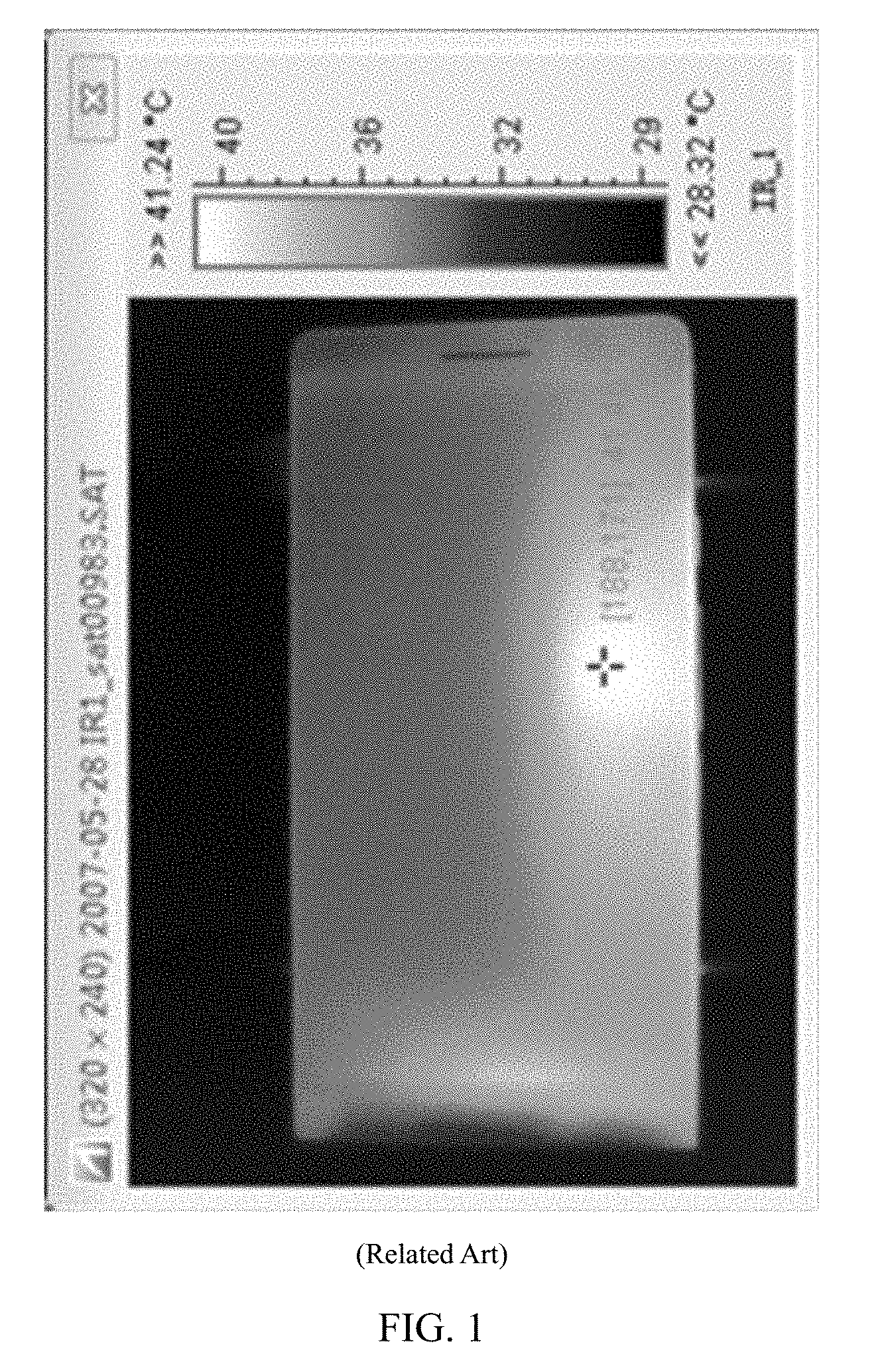
With the rapid development of configurations of mobile terminals, for example, a dominant frequency of an internal chip of the mobile terminal is increasingly high, an access speed of a memory is increasingly high, and correspondingly, radio frequency power amplification and a power management effect are increasingly high, overall heating of the mobile terminal correspondingly increases. Therefore, heat dissipation processing (which is also referred to as a heat dissipation design) on the mobile terminal becomes particularly important. Because of size, waterproof and dustproof, and noise requirements for the mobile terminal, a hermetic seal feature of the mobile terminal restricts using a fan to forcibly dissipate heat. In a case in which the heat can be dissipated only by using a surface of the mobile terminal, performing effective heat dissipation path management by combining a use habit and a heat reception feature becomes a core of the heat dissipation design of the mobile terminal. Research shows that, because the mobile terminal is designed to be thinner, to increase a battery capacity, an overlapping design of a battery and a circuit board becomes a concurrent design on a same plane. Consequently, heat source components (such as the biggest heating component CPU in the mobile terminal) in the mobile terminal are densely centralized in areas corresponding to a side frame and a circuit board that are of the mobile terminal. It can be known according to FIG. 1 that colors of the two areas in which the heat is relatively concentrated are relatively bright and temperatures are relatively high. However, an area in which heat sources are concentrated is a location that a user often touches when using the mobile terminal. Therefore, more effective heat dissipation processing needs to be performed on the mobile terminal.
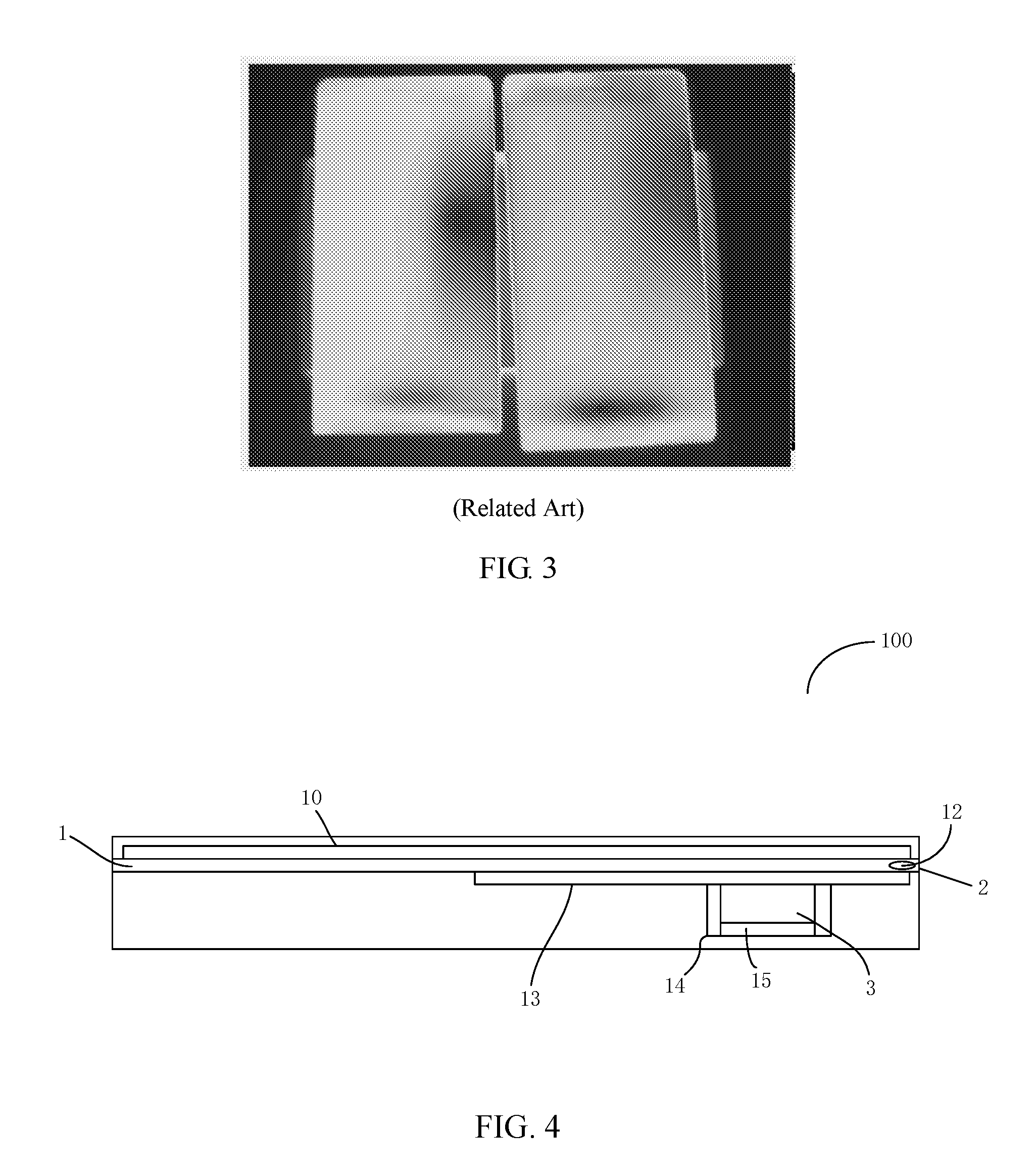
In the related art, heat is generally transferred to a battery area by using a graphite sheet or by using a holder material of a higher heat conductivity coefficient, so as to reduce a temperature of an orthogonal projection area of the circuit board of the mobile terminal with respect to the holder. It can be obtained according to FIG. 2 and FIG. 3 that the heat dissipation design reduces a temperature of an area, corresponding to the circuit board, of the mobile terminal, but because of high heat conductivity of the holder, the heat can be more rapidly transferred to the side frame of the mobile terminal; as a result, a large quantity of heat sources are concentrated on the side frame of the mobile terminal (as can be seen in FIG. 2, a color of this area is relatively bright, which shows that the temperature of this area is relatively high).
SUMMARY
Embodiments of the present disclosure provide a holder, so as to reduce heat at a side frame of a mobile terminal.
According to an aspect, a holder is provided, located in a mobile terminal, where the holder includes a heat conduction area and a heat insulation area, the heat insulation area is close to an edge of the holder, the heat insulation area is adjacent to the heat conduction area, and a heat emitting element in the mobile terminal is proximate to the heat conduction area.
With reference to the first aspect, in a first possible implementation manner, the mobile terminal includes a side frame, the side frame surrounds the holder, and the heat insulation area isolates the heat emitting element from the side frame.
With reference to the first aspect, in a second possible implementation manner, the heat insulation area is provided with a heat insulation cavity, and the heat insulation cavity is vacuum or is filled with air.
With reference to the first aspect, in a third possible implementation manner, the heat insulation area is provided with a heat insulation cavity, the heat insulation cavity has a low heat conduction material, and the low heat conduction material has a heat conductivity coefficient range of 0-0.026 W/m-K.
With reference to the second possible implementation manner of the first aspect or the third possible implementation manner of the first aspect, in a fourth possible implementation manner, the heat insulation cavity is at least one strip-shaped hole or at least one elliptical hole.
With reference to the second possible implementation manner of the first aspect or the third possible implementation manner of the first aspect, in a fifth possible implementation manner, the heat insulation cavity includes at least one groove, and the groove is provided at an edge of the heat insulation area.
With reference to the first aspect, in a sixth possible implementation manner, an area of the heat insulation cavity occupies at least 50% of an area of the heat insulation area.
With reference to the first aspect, in a seventh possible implementation manner, the heat insulation area is made from a low heat conduction material, and the low heat conduction material has a heat conductivity coefficient range of 0-0.026 W/m-K.
With reference to the first aspect, in an eighth possible implementation manner, a material of the holder is a heat conduction material.
With reference to any one of the first aspect to the eighth possible implementation manner, in a ninth possible implementation manner, the holder is a display screen holder.
According to a second aspect, a mobile terminal is provided, including: a side frame, a heat emitting element, and the holder, where the side frame surrounds the holder.
According to the holder or the mobile terminal having the holder in the embodiments of the present disclosure, the heat insulation area is provided on the holder, and the heat insulation area is located at the edge of the holder and is adjacent to the heat conduction area, so that, in a process of transferring heat in the heat conduction area to the side frame, the heat is impeded by the heat insulation area, thereby reducing heat at the side frame.
BRIEF DESCRIPTION OF DRAWINGS
To describe the technical solutions in the embodiments of the present disclosure more clearly, the following briefly describes the accompanying drawings required for describing the embodiments. Apparently, the accompanying drawings in the following description show merely some embodiments of the present disclosure, and persons of ordinary skill in the art may still derive other drawings from these accompanying drawings without creative efforts.
FIG. 1 and FIG. 2 are schematic diagrams of infrared temperature distribution of a front plane and a rear plane that are of a mobile terminal in the related art;
FIG. 3 is a schematic diagram of infrared temperature distribution of a front plane and a rear plane that are of another mobile terminal in the related art;
FIG. 4 is a schematic diagram of a mobile terminal according to Embodiment 1 of the present disclosure;
FIG. 5 is a schematic diagram of a holder in FIG. 4;
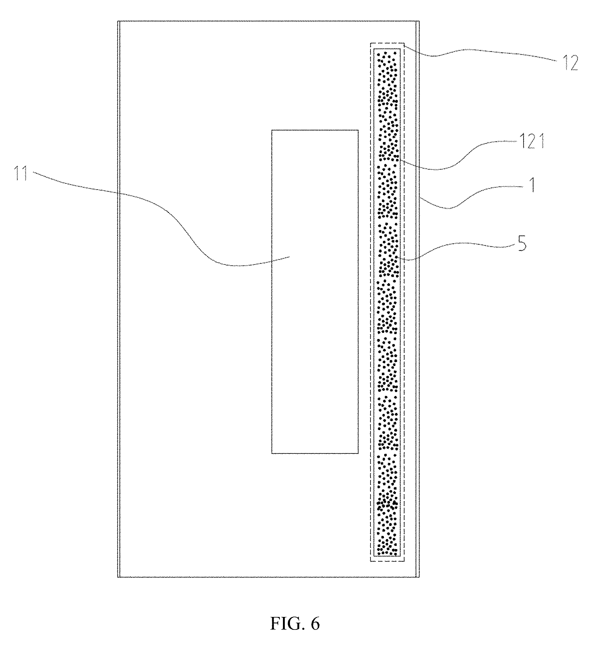
FIG. 6 is a schematic diagram of another holder in FIG. 4;
FIG. 7 is a schematic diagram of a holder according to Embodiment 2 of the present disclosure;
FIG. 8 is a schematic diagram of another holder provided in FIG. 7; and
FIG. 9 is a schematic diagram of temperature distribution of the mobile terminal in FIG. 4.
DESCRIPTION OF EMBODIMENTS
The following clearly and completely describes the technical solutions in the embodiments of the present disclosure with reference to the accompanying drawings in the embodiments of the present disclosure. Apparently, the described embodiments are merely some but not all of the embodiments of the present disclosure. All other embodiments obtained by persons of ordinary skill in the art based on the embodiments of the present disclosure without creative efforts shall fall within the protection scope of the present disclosure.
Referring to FIG. 4 and FIG. 5, a first embodiment of the present disclosure provides a mobile terminal 100. The mobile terminal 100 includes a side frame 2, a heat emitting element 3, and a holder 1. The holder 1 is located in the mobile terminal 100, the holder 1 includes a heat conduction area 11 and a heat insulation area 12, the heat insulation area 12 is close to an edge of the holder 1, the heat insulation area 12 is adjacent to the heat conduction area 11, the heat emitting element 3 in the mobile terminal is proximate to the heat conduction area 11, and the side frame 2 surrounds the holder 1.
According to the mobile terminal 100 provided in this embodiment of the present disclosure, the heat insulation area 12 is provided on the holder 1, and the heat insulation area 12 is close to the edge of the holder 1 and is adjacent to the heat conduction area 11, so that, in a process of transferring heat in the heat conduction area 11 to the side frame 2, the heat is impeded by the heat insulation area 12, thereby reducing heat at the side frame 2.
The heat insulation area 12 may be located between the side frame 2 and the heat conduction area 11.
In this embodiment, the mobile terminal 100 is a smartphone. Certainly, in another embodiment, the mobile terminal 100 may also be a tablet computer.
In this embodiment, the side frame 2 includes a pair of long edges L and a pair of short edges D. When a user uses the mobile terminal 100, the user generally holds the pair of long edges L. The heat emitting element 3 is integrated on a circuit board. The mobile terminal may include a shielding can 14, and the shielding can 14 surrounds the heat emitting element 3 on the circuit board, to prevent an electromagnetic field generated by the heat emitting element 3 from diffusing out, and prevent the electromagnetic field from being affected by an outside electromagnetic field. Optionally, stainless steel having a thickness of 0.2 mm and copper-nickel-zinc alloy having a thickness of 0.2 mm may be used as materials of the shielding can 14. There may be a heat conduction medium 15 between the shielding can 14 and the heat emitting element 3.
There may also be a heat conduction medium on the shielding can, the heat conduction medium is proximate to the heat conduction area 11, and the heat emitting element 3 is proximate to the heat conduction area 11, so that heat generated by the heat emitting element 3 can be more rapidly transferred to the holder 1. The heat may be transferred to the outside of the mobile terminal 100 by using the holder 1. The heat conduction medium may be heat conduction silica gel.
It can be understood that the mobile terminal may not have a shielding can. The holder 1 may play a role of a shielding can, that is, prevent the electromagnetic field generated by the heat emitting element 3 from diffusing out, and prevent the electromagnetic field from being affected by an outside electromagnetic field.
In this embodiment, the heat emitting element 3 is close to a right long edge L1 at a right side of the side frame 2, the heat conduction area 11 is generally provided close to the right long edge L1. The heat conduction area 11 is relatively near the right long edge L1; therefore, heat is much concentrated at the right long edge L1. To improve this situation, the heat insulation area 12 is provided close to the right long edge L1. Certainly, in another embodiment, the heat insulation area 12 may also be provided between the heat conduction area 11 and the short edge D according to an actual need, or provided between the heat conduction area 11 and the other long edge L; or the heat insulation area 12 may be separately disposed between the heat conduction area 11 and the long edge L and between the heat conduction area 11 and the short edge D.
For further improvement, the mobile terminal includes the side frame 2, the side frame 2 surrounds the holder 1, and the heat insulation area 12 may completely isolate the heat emitting element 3 from the side frame 2. The heat insulation area 12 completely isolates the heat emitting element 3 from the side frame 2, so that when the heat generated by the heat emitting element 3 is transferred to the side frame 2, the heat can pass through the heat insulation area 12, so as to impede all the heat, to improve a heat insulation effect of the heat insulation area 12.
In this embodiment, two ends, oppositely provided along a direction of the long edge L, of the heat insulation area 12 respectively exceed two ends, oppositely provided along the direction of the long edge L, of the heat conduction area 11. A size of the heat insulation area along the direction of the long edge L is greater than a size of the heat conduction area 11 along the direction of the long edge L; therefore, when the heat emitting element 3 emits heat and the heat is transferred to the heat conduction area 11, and when the heat in the heat conduction area 11 is transferred to the side frame, the heat passes through the heat insulation area 12, so that the heat insulation area 12 can prevent the heat in the heat conduction area 11. Certainly, in another embodiment, the mobile terminal 100 may further perform analysis according to main heat distribution in the heat conduction area 11, and then correspondingly set a size of the heat insulation area 12. That is, a length of the heat insulation area 12 along a length extending direction of the holder 1 is not necessarily greater than a length of the heat conduction area 11 along the holder 1, and may be less than or equal to the length of the heat conduction area 11 along the holder 1, as long as heat reception at a side of the mobile terminal 100 can satisfy an actually needed situation.
For further improvement, referring to FIG. 5, the heat insulation area 12 is provided with a heat insulation cavity 121, and the heat insulation cavity 121 is vacuum or is filled with air 5. A heat conductivity coefficient of the air 5 is approximately 0.026 W/m-K in a closed small gap and is far less than that of another material. For example, a heat conductivity coefficient of plastic is greater than 0.2 W/m-K, a heat conductivity coefficient of metal is within 10-400 W/m-K, and a heat conductivity coefficient of glass is approximately 2 W/m-K. The materials listed above are generally used to manufacture the holder 1. A medium with a relatively small heat conductivity coefficient is introduced to a material with a relatively large heat conductivity coefficient, so that heat resistance is formed at a location at which the medium with the relatively small heat conductivity coefficient is introduced in the holder 1, so as to form the heat insulation area 12. As vacuum is not heat-conductive, or the air 5 in the cavity has a small heat conductivity coefficient, heat resistance is formed at the location at which the medium of the relatively small heat conductivity coefficient is introduced in the holder 1, so that the heat insulation effect is better. In this embodiment, the heat insulation cavity 121 is filled with the air 5. Generally, in the related art, the air 5 exists in the mobile terminal 100. To enable the heat insulation cavity 121 to have the heat insulation effect, making the heat insulation cavity 121 have the air 5 is a relatively easy way, or the interior of the mobile terminal 100 may be made to be in a vacuum environment to make the heat insulation cavity 121 be vacuum. Certainly, in another embodiment, the heat insulation cavity 121 may also form heat resistance in another manner. For example, the heat insulation cavity 121 is configured to accommodate a low heat conduction material, and the low heat conduction material has a heat conductivity coefficient range of 0-0.026 W/m-K. In another embodiment, the heat insulation area 12 may be made from a low heat conduction material, and the low heat conduction material has a heat conductivity coefficient range of 0-0.026 W/m-K. The heat insulation area 12 is made from a material having a heat conductivity coefficient range of 0-0.26 W/m-K, and a heat conductivity coefficient of a material whose heat conductivity coefficient is within the heat conductivity coefficient range is far less than that of another material. For example, metal has a heat conductivity coefficient of 10-400 W/m-K, and glass has a heat conductivity coefficient of approximately 2 W/m-K. The materials listed above are generally used to manufacture the holder 1. A medium with a relatively small heat conductivity coefficient is introduced to a material with a relatively large heat conductivity coefficient, so that heat resistance is formed at a location at which the medium with the relatively small heat conductivity coefficient is introduced in the holder 1, so as to form the heat insulation area 12.
For further improvement, the heat insulation cavity 121 is at least one strip-shaped hole or at least one elliptical hole. The heat insulation area 12 is provided with the hole-shaped heat insulation cavity 121, so that processing on the holder 1 is relatively simple. In this embodiment, the heat insulation cavity 121 is at least one strip-shaped hole. Certainly, in another embodiment, the heat insulation cavity 121 may also be at least one elliptical hole or a hole of another shape.
The heat emitting element 3 may be a heating chip and there are three heat insulation cavities 121, which are strip-shaped holes. The holes have a length of 5 mm and have a width of 1 mm, and a gap between the holes is greater than 1 mm and less than 2 mm.
For further improvement, an area of the heat insulation cavity 121 occupies at least 50% of an area of the heat insulation area 12. The heat insulation cavity 121 is vacuum or is filled with the air 5, so that a heat-conducting property of the heat insulation cavity 121 becomes poorer, and heat resistance is formed. Therefore, a larger area of the heat insulation cavity 121 indicates a better heat insulation effect of the heat insulation area 12.
In this embodiment, in consideration of general strength of the material of the holder 1, there are seven heat insulation cavities 121, which are strip-shaped holes. Each of the strip-shaped holes has a dimension of 5 mm along the direction of the long edge L (that is, each of the strip-shaped holes has a length of 5 mm along the direction of the long edge L). The strip-shaped hole has a dimension of 1 mm along a direction perpendicular to the long edge L (that is, each of the strip-shaped holes has a length of 1 mm along a direction of the short edge). A spacing between two neighboring strip-shaped holes is 2 mm. The area of the heat insulation cavity 121 occupies approximately 50% of the area of the heat insulation area 12.
Referring to FIG. 6, when the strength of the holder 1 is higher, the heat insulation cavity 121 may also be one strip-shaped hole. That is, the area of the heat insulation cavity 121 occupies 100% of the area of the heat insulation area 12, thereby achieving a better heat insulation effect.
Certainly, in a second embodiment, as shown in FIG. 7, a heat insulation cavity 221 includes at least one groove 221a, where the groove 221a is provided at an edge of a heat insulation area 22. An inward dentiform structure is formed at an edge of the heat insulation area 22 because of existence of the groove 221a. In consideration of strength of a material of the holder 1, the heat insulation cavity 221 may include seven grooves 221a. Each of the groove 221a has a dimension of 5 mm along the direction of the long edge L (that is, each of the grooves 221a has a length of 5 mm along the direction of the long edge L). The groove 221a has a dimension of 1.5 mm along a direction perpendicular to the long edge L (that is, the groove has a length of 1.5 mm along the direction of the short edge). A spacing between two neighboring grooves 221a is 2 mm. An area of the heat insulation cavity 221 occupies approximately 50% of an area of the heat insulation area 22.
As shown in FIG. 8, when the strength of the holder 1 is higher, the heat insulation cavity 221 may also include one groove 221a. That is, the area of the heat insulation cavity 221 occupies 100% of the area of the heat insulation area 22, thereby achieving a better heat insulation effect. In another embodiment, the heat insulation cavity 221 may also be provided on a same holder 1 in a hole shape and in a form of the groove 221a according to an actual need.
Referring to FIG. 9, for a heat distribution status after the holder 1 is provided with the heat insulation cavity 121. Heat in the mobile terminal 100 is evenly distributed, and the heat is not concentrated on the side frame 2 of the mobile terminal 100.
For further improvement, the material of the holder 1 is a heat conduction material. Heat in the heat emitting element 3 is rapidly transferred to the holder 1 by means of heat conductivity of the holder 1, and then the heat is transferred to the outside of the mobile terminal 100, so that heat dissipation processing on the mobile terminal 100 is more effective. In this embodiment, to ensure a heat-conducting property of the holder 1, the material of the holder 1 may be graphite. When the holder 1 is located between a display screen 10 and the circuit board 13, heat in the circuit board 13 can be more rapidly transferred to the holder 1. In addition, the heat in the holder 1 can be more rapidly transferred to the outside of the mobile terminal 100 because of high heat conductivity of the holder 1, so that the heat dissipation processing on the mobile terminal 100 is more effective. Certainly, in another embodiment, the material of the holder 1 may also be another material according to an actual need of the mobile terminal 100. For example, if the mobile terminal 100 does not have a relatively high requirement on heat dissipation performance, the material of the holder 1 may also be a material with a relatively low heat-conducting property.
When the mobile terminal 100 starts to be equipped, the heat emitting element 3 first needs to be proximate to the heat conduction area 11, and the shielding can and the heat conduction medium are disposed between the heat emitting element 3 and the heat conduction area 11, so as to implement a shielding effect and a heat conduction effect. When the heat emitting element 3 starts to generate heat, the heat is transferred from the heat emitting element 3 to the holder 1 because of the heat conductivity of the holder 1, and subsequently the holder 1 transfers the heat to the side frame 2 of the mobile terminal 100. In a process of transferring the heat in the heat conduction area 11 to the side, because of the existence of the heat insulation area 12, the heat is impeded by heat resistance formed in the heat insulation area 12, so that heat at the side is relatively low, thereby ensuring that the heat at the side frame 2 of a housing of the mobile terminal 100 is relatively low.
The holder 1 is a display screen holder.
According to the mobile terminal 100 provided in this embodiment of the present disclosure, the heat insulation area 12 is provided on the holder 1, and the heat insulation area 12 is close to the edge of the holder 1 and is adjacent to the heat conduction area 11, so that, in a process of transferring heat in the heat conduction area 11 to the side frame 2, the heat is impeded by the heat insulation area 12, thereby reducing heat at the side frame 2.
In addition, the heat insulation area 12 completely isolates the heat emitting element 3 from the side frame 2, so that the heat insulation effect of the heat insulation area 12 is improved. The heat insulation area 12 is provided with the heat insulation cavity 121, where the heat insulation cavity 121 is vacuum or is filled with the air 5, so that heat insulation is relatively easy to be implemented in the heat insulation area 12. The heat insulation area 12 is made from a low heat conduction material, and the low heat conduction material has a thermal insulation coefficient range of 0-0.026 W/m-K, so that the heat insulation effect of the heat insulation area 12 is better. The heat insulation cavity 121 is at least one strip-shaped hole or at least one elliptical hole, so that processing on the holder 1 is relatively simple. The heat insulation cavity 121 includes at least one groove 221, and the groove 221 is provided at an edge of the heat insulation area 12, so that there are various providing manners for the heat insulation cavity 121. The area of the heat insulation cavity 121 occupies at least 50% of the area of the heat insulation area 12, so that the heat insulation effect of the heat insulation area 12 is better. The material of the holder 1 is a heat conduction material, so that the heat dissipation processing on the mobile terminal 100 is more effective.
Finally, it should be noted that the foregoing embodiments are merely intended for describing the technical solutions of the present disclosure but not for limiting the present disclosure. Although the present disclosure is described in detail with reference to the foregoing embodiments, persons of ordinary skill in the art should understand that they may still make modifications to the technical solutions described in the foregoing embodiments or make equivalent replacements to some technical features thereof, without departing from the spirit and scope of the technical solutions of the embodiments of the present disclosure.
* * * * *
D00000
D00001
D00002
D00003
D00004
D00005
D00006
D00007
D00008
XML
uspto.report is an independent third-party trademark research tool that is not affiliated, endorsed, or sponsored by the United States Patent and Trademark Office (USPTO) or any other governmental organization. The information provided by uspto.report is based on publicly available data at the time of writing and is intended for informational purposes only.
While we strive to provide accurate and up-to-date information, we do not guarantee the accuracy, completeness, reliability, or suitability of the information displayed on this site. The use of this site is at your own risk. Any reliance you place on such information is therefore strictly at your own risk.
All official trademark data, including owner information, should be verified by visiting the official USPTO website at www.uspto.gov. This site is not intended to replace professional legal advice and should not be used as a substitute for consulting with a legal professional who is knowledgeable about trademark law.