Electric current based engine auto stop inhibit algorithm and system implementing same
Sangameswaran , et al. Nov
U.S. patent number 10,480,477 [Application Number 13/179,747] was granted by the patent office on 2019-11-19 for electric current based engine auto stop inhibit algorithm and system implementing same. This patent grant is currently assigned to Ford Global Technologies, LLC. The grantee listed for this patent is David Celinske, Kevin Roy Harpenau, Kirk Pebley, Eric Michael Rademacher, Sangeetha Sangameswaran. Invention is credited to David Celinske, Kevin Roy Harpenau, Kirk Pebley, Eric Michael Rademacher, Sangeetha Sangameswaran.


| United States Patent | 10,480,477 |
| Sangameswaran , et al. | November 19, 2019 |
Electric current based engine auto stop inhibit algorithm and system implementing same
Abstract
A vehicle includes an engine and at least one controller. The at least one controller periodically determines an estimated current to be demanded by vehicle electrical loads during an auto stop of the engine, compares the estimated current with a threshold current, and inhibits an auto stop of the engine if the estimated current is greater than the threshold current for a predetermined period of time.
| Inventors: | Sangameswaran; Sangeetha (Canton, MI), Harpenau; Kevin Roy (Peachtree City, GA), Pebley; Kirk (Novi, MI), Celinske; David (Wolverine Lake, MI), Rademacher; Eric Michael (Royal Oak, MI) | ||||||||||
|---|---|---|---|---|---|---|---|---|---|---|---|
| Applicant: |
|
||||||||||
| Assignee: | Ford Global Technologies, LLC
(Dearborn, MI) |
||||||||||
| Family ID: | 47425805 | ||||||||||
| Appl. No.: | 13/179,747 | ||||||||||
| Filed: | July 11, 2011 |
Prior Publication Data
| Document Identifier | Publication Date | |
|---|---|---|
| US 20130018569 A1 | Jan 17, 2013 | |
| Current U.S. Class: | 1/1 |
| Current CPC Class: | F02N 11/0825 (20130101); Y02T 10/48 (20130101); F02N 2200/062 (20130101); Y02T 10/72 (20130101); F02N 2200/0809 (20130101); Y02T 10/7258 (20130101); F02N 11/04 (20130101); Y02T 10/40 (20130101) |
| Current International Class: | F02N 11/08 (20060101); F02N 11/04 (20060101) |
| Field of Search: | ;123/179.4,198D,198DB,198DC ;701/41,112,113 |
References Cited [Referenced By]
U.S. Patent Documents
| 4021677 | May 1977 | Rosen et al. |
| 4284053 | August 1981 | Merrick |
| 4408582 | October 1983 | Merrick |
| 4467671 | August 1984 | Hasegawa |
| 4479472 | October 1984 | Shimamura |
| 4520271 | May 1985 | Goertler |
| 4625281 | November 1986 | Deutsch |
| 4788487 | November 1988 | Picklesimer |
| 4836164 | June 1989 | Morozumi et al. |
| 4898005 | February 1990 | Sakurai |
| 5072597 | December 1991 | Bromley et al. |
| 5163399 | November 1992 | Bolander et al. |
| 5216895 | June 1993 | Kawai et al. |
| 5336932 | August 1994 | Barske |
| 5365445 | November 1994 | Takizawa |
| 5463993 | November 1995 | Livshits et al. |
| 5559704 | September 1996 | Vanek et al. |
| 5806485 | September 1998 | DeGeorge |
| 6019183 | February 2000 | Shimasaki |
| 6037749 | March 2000 | Parsonage |
| 6226585 | May 2001 | Cullen |
| 6316842 | November 2001 | Kuroda |
| 6379283 | April 2002 | Cullen |
| 6429539 | August 2002 | Suzuki et al. |
| 6553958 | April 2003 | Kolmanovsky et al. |
| 6564765 | May 2003 | Kuroda |
| 6564774 | May 2003 | Ellims et al. |
| 6570266 | May 2003 | Wakashiro |
| 6608394 | August 2003 | Osada et al. |
| 6624529 | September 2003 | Obayashi |
| 6668224 | December 2003 | Kawai et al. |
| 6755032 | June 2004 | Kotwicki et al. |
| 6763296 | July 2004 | Aldrich, III et al. |
| 6805090 | October 2004 | Bertness et al. |
| 6845305 | January 2005 | Raftari et al. |
| 6913558 | July 2005 | Mori |
| 6925369 | August 2005 | Obayashi |
| 7017360 | March 2006 | Kotwicki et al. |
| 7032393 | April 2006 | Tamai et al. |
| 7173347 | February 2007 | Tani |
| 7347175 | March 2008 | Lupo |
| 7503413 | March 2009 | Jiang |
| 7516811 | April 2009 | Kolpasky |
| 7552705 | June 2009 | Serkh et al. |
| 7635922 | December 2009 | Becker |
| 7665557 | February 2010 | Hughes |
| 7745953 | June 2010 | Puccetti et al. |
| 8205594 | June 2012 | Fore et al. |
| 8406954 | March 2013 | Whitney et al. |
| 8552688 | October 2013 | Ueda |
| 8560202 | October 2013 | Pebley et al. |
| 2002/0113441 | August 2002 | Obayashi |
| 2003/0018415 | January 2003 | Sonobe et al. |
| 2003/0233835 | December 2003 | Tomita et al. |
| 2004/0084232 | May 2004 | Obayashi |
| 2004/0112074 | June 2004 | Komura et al. |
| 2004/0231315 | November 2004 | Gonzalez |
| 2005/0044873 | March 2005 | Tamai et al. |
| 2005/0193747 | September 2005 | Kajimoto et al. |
| 2005/0285445 | December 2005 | Wruck |
| 2006/0028778 | February 2006 | O'Gorman et al. |
| 2006/0116797 | June 2006 | Moran |
| 2006/0137643 | June 2006 | Thompson et al. |
| 2007/0007056 | January 2007 | Bowers et al. |
| 2007/0080006 | April 2007 | Yamaguchi |
| 2007/0170778 | July 2007 | Yamaguchi |
| 2007/0225882 | September 2007 | Yamaguchi |
| 2007/0255488 | November 2007 | Okubo et al. |
| 2008/0306670 | December 2008 | Masterson |
| 2009/0015203 | January 2009 | Oakes |
| 2009/0018707 | January 2009 | Oakes |
| 2009/0024264 | January 2009 | Aldrich, III et al. |
| 2009/0241883 | October 2009 | Nagoshi |
| 2010/0042277 | February 2010 | Naik et al. |
| 2010/0050671 | March 2010 | Kahn et al. |
| 2010/0125383 | May 2010 | Caouette |
| 2010/0145562 | June 2010 | Moran |
| 2010/0163220 | July 2010 | Nakajima |
| 2010/0217484 | August 2010 | Mizuno |
| 2010/0222973 | September 2010 | Senda |
| 2010/0269776 | October 2010 | Mizuno |
| 2012/0083988 | April 2012 | Miyata et al. |
| 2012/0109469 | May 2012 | Pebley et al. |
| 2012/0253595 | October 2012 | Oakes |
| 2012/0271525 | October 2012 | Bucci et al. |
| 2012/0304670 | December 2012 | Kumar et al. |
| 2013/0060444 | March 2013 | Matsunaga et al. |
| 2013/0173142 | July 2013 | Kato |
| 2013/0226440 | August 2013 | Rademacher et al. |
| 102877961 | Jan 2013 | CN | |||
| 3307220 | Sep 1984 | DE | |||
| 2138712 | Dec 2009 | EP | |||
| 58209613 | Dec 1983 | JP | |||
| 10304503 | Nov 1998 | JP | |||
| 10325346 | Dec 1998 | JP | |||
| H10325346 | Dec 1998 | JP | |||
| H10325436 | Dec 1998 | JP | |||
| 2001173480 | Jun 2001 | JP | |||
| 2001173480 | Jun 2001 | JP | |||
| 2006097648 | Apr 2006 | JP | |||
| 2006220113 | Aug 2006 | JP | |||
| 2009007988 | Jan 2009 | JP | |||
| 2009007998 | Jan 2009 | JP | |||
| 2009243292 | Oct 2009 | JP | |||
| 2010116877 | May 2010 | JP | |||
| 2010265785 | Nov 2010 | JP | |||
| 2008089935 | Jul 2008 | WO | |||
Other References
|
"NPL_A_Guide_To_Battery_Specifications_Dec2008"; retreived from the internet Dec. 19, 2018; http://web.mit.edu/evt/summary_battery_specifications.pdf; published Dec. 2008 (Year: 2008). cited by examiner. |
Primary Examiner: Vilakazi; Sizo B
Assistant Examiner: Kirby; Brian R
Attorney, Agent or Firm: Kelley; David B. Brooks Kushman P.C.
Claims
What is claimed is:
1. A vehicle comprising: an engine; and at least one controller configured to inhibit an auto stop of the engine in response to expected increases and decreases to currents consumed by climate system accessory loads or power steering system accessory loads once the engine has been auto stopped resulting in an estimated current to be demanded by the vehicle accessory loads during an auto stop of the engine being greater than a threshold current.
2. The vehicle of claim 1 wherein inhibiting an auto stop of the engine includes preventing the engine from stopping.
3. The vehicle of claim 1 wherein the at least one controller is further configured to allow an auto stop of the engine in response to the estimated current being less than the threshold current.
4. A vehicle comprising: an engine; and a controller configured to detect an engine auto stop inhibit condition responsive to expected increases and decreases to currents consumed by vehicle accessory fan loads or vehicle accessory pump loads once the engine has been auto stopped resulting in an estimate of current to be demanded by the vehicle accessory loads during an auto stop of the engine being greater than a threshold current, and to prevent the engine from auto stopping.
5. The vehicle of claim 4 wherein the at least one controller is further configured to detect an engine auto stop permit condition responsive to the estimate of current being less than the threshold current, and to allow the engine to auto stop.
6. A method for controlling a vehicle engine comprising: inhibiting an auto stop of the engine responsive to expected changes to currents consumed by climate system accessory loads or power steering system accessory loads once the engine has been auto stopped resulting in an estimated current to be demanded by the vehicle accessory loads being greater than a threshold current; and allowing an auto stop of the engine responsive to the estimated current being less than the threshold current.
7. The method of claim 6 further comprising controlling the vehicle accessory loads during an auto stop of the engine such that the vehicle accessory loads consume an amount of current not greater than the estimated current.
8. The method of claim 6 wherein inhibiting an auto stop of the engine includes preventing the engine from stopping.
Description
TECHNICAL FIELD
This disclosure relates to techniques for determining whether to inhibit an engine auto stop based on estimates of electric current demand of electrical loads.
BACKGROUND
A micro-hybrid vehicle may stop its internal combustion engine for a period of time during intervals of a drive cycle when vehicle speed approaches or is equal to 0. These engine auto stops may improve fuel economy by reducing engine idle time (and thus fuel consumption) for the drive cycle.
SUMMARY
A vehicle may include an engine and at least one controller. The at least one controller may be configured to periodically determine an estimated current to be demanded by vehicle electrical loads during an auto stop of the engine, to compare the estimated current with a threshold current, and to inhibit an auto stop of the engine if the estimated current is greater than the threshold current for a predetermined period of time.
A vehicle may include an engine and at least one controller configured to detect an engine auto stop inhibit condition when an estimate of current to be demanded by vehicle electrical loads during an auto stop of the engine is greater than a threshold current. In response to detecting the engine auto stop inhibit condition, the at least one controller may prevent the engine from auto stopping.
A method for controlling an engine of a vehicle may include determining an estimated current to be demanded by vehicle electrical loads during an auto stop of the engine, comparing the estimated current with a threshold current, inhibiting an auto stop of the engine if the estimated current is greater than the threshold current, and allowing an auto stop of the engine if the estimated current is less than the threshold current.
BRIEF DESCRIPTION OF THE DRAWINGS
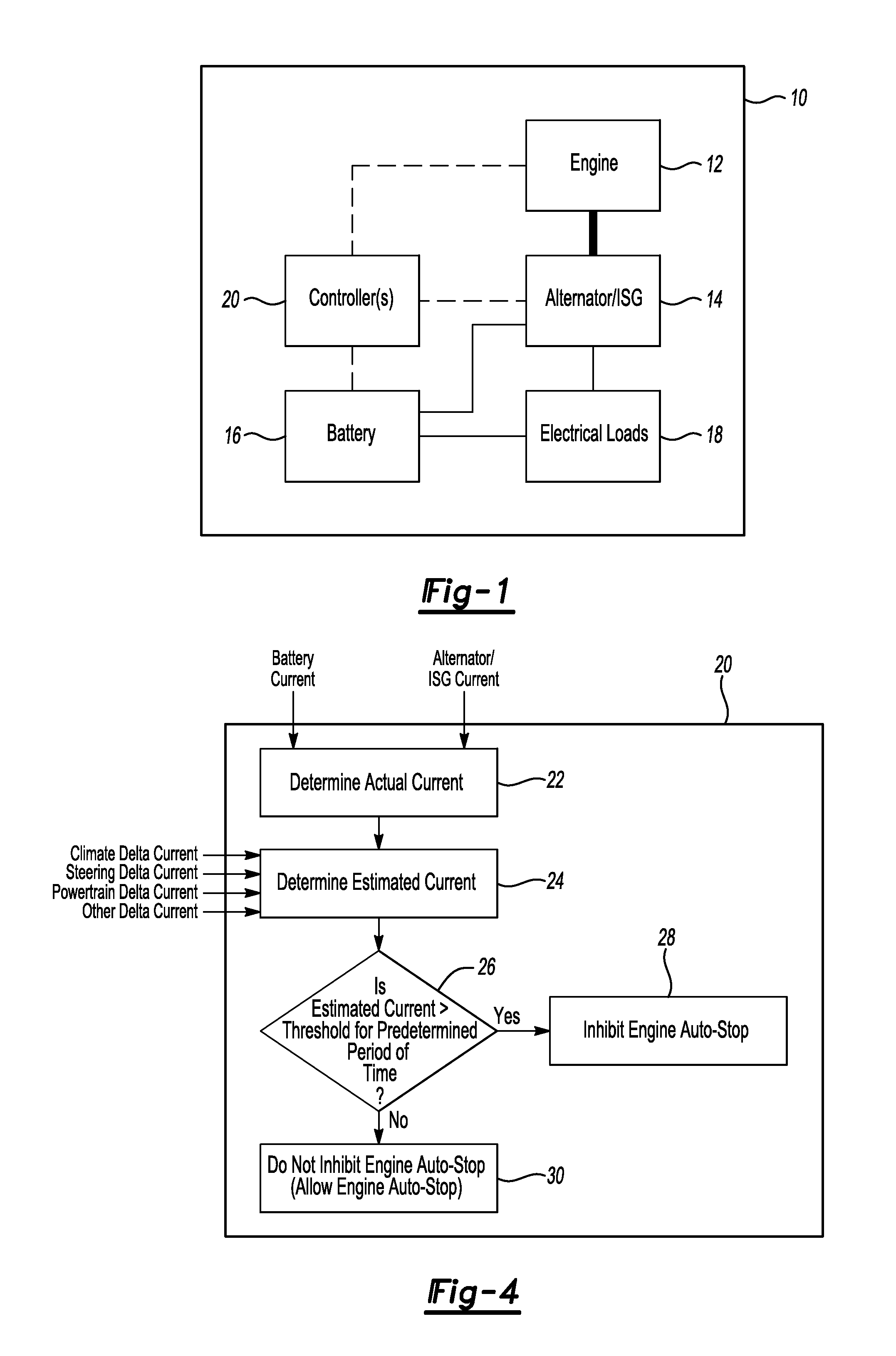
FIG. 1 is a block diagram of a micro-hybrid vehicle.
FIG. 2 is a plot of engine status versus time before, during and after an engine stop/start event.
FIG. 3 is a plot of actual and estimated system currents associated with the plot of FIG. 2.
FIG. 4 is a flow chart of an algorithm for determining whether to inhibit an auto stop of an engine.
DETAILED DESCRIPTION
As required, detailed embodiments of the present invention are disclosed herein; however, it is to be understood that the disclosed embodiments are merely exemplary of the invention that may be embodied in various and alternative forms. The figures are not necessarily to scale; some features may be exaggerated or minimized to show details of particular components. Therefore, specific structural and functional details disclosed herein are not to be interpreted as limiting, but merely as a representative basis for teaching one skilled in the art to variously employ the present invention.
Referring to FIG. 1, a micro-hybrid vehicle 10 may include an engine 12, an alternator or integrated starter generator 14, a battery 16 (e.g., a 12 V battery), electrical loads 18 (e.g., pumps of a climate control system, a power steering assist system, etc.) in communication with/under the control of one or more controllers 20 (as indicated by dashed line). The engine 12 is mechanically connected with the alternator or integrated starter generator 14 (as indicated by heavy line) such that the engine 12 may drive the alternator or integrated starter generator 14 to generate electric current. The alternator or integrated starter generator 14 and battery 16 are electrically connected with each other and the electrical loads 18 (as indicated by thin line). Hence, the alternator or integrated starter generator 14 may charge the battery 16; the electrical loads 18 may consume electric current provided by the alternator or integrated starter generator 14 and/or battery 16.
The controllers 20 may initiate an auto stop or auto start of the engine 12. As the vehicle 10 comes to a stop, for example, the controllers 20 may issue a command to begin the process to stop the engine 12, thus preventing the alternator or integrated starter generator 14 from providing electric current to the electrical loads 18. The battery 16 may provide electric current to the electrical loads 18 while the engine 12 is stopped. As a brake pedal (not shown) is disengaged (and/or an accelerator pedal (not shown) is engaged) after an engine auto stop, the controllers 20 may issue a command to begin the process to start the engine 12, thus enabling the alternator or integrated starter generator 14 to provide electric current to the electrical loads 18.
Referring to FIG. 2, an engine auto stop event may include several stages: "auto-stop begin," which marks the beginning of the engine auto stop event; "preparing for engine auto-stop," which is the time period during which vehicle systems as well as the engine are prepared for the impending engine stop (if an auto stop inhibit condition is detected during this stage, the preparation for the impending engine stop is discontinued and the vehicle systems and engine are returned to their normal operating modes); "fuel shutoff," which marks the point at which fuel flow to the engine is stopped; "engine stopping," which is the time period during which the engine speed reduces to 0; "below fuel restart," which marks the point after which if a restart is requested during the "engine stopping" stage, the starter may need to be engaged to crank the engine (if a restart is requested before "below fuel restart" and during the "engine stopping" stage, the engine may be restarted by turning the flow of fuel back on); "engine speed=0," which marks the point at which the engine speed is near or equal to 0; "engine auto-stopped," which is the time period during which the engine is off; "starter engage," which marks the point at which the starter starts to crank the engine in an effort to start the engine (in response to detecting an engine auto start condition); "starter cranking engine," which is the time period during which the engine is unable to crank under its own power; "starter disengage," which marks the point at which the engine is able to crank under its own power; "engine speed increasing," which is the time period during which the speed of the engine increases to its running speed (a speed at or above target idle speed); and, "auto-start end," which marks the point at which the speed of the engine achieves its running speed.
Referring again to FIG. 1, the electrical loads 18 may be operative while the engine 12 is off during an engine stop/start event. For example, pumps associated with a climate control system may be on during this time period. Hence, the battery 16 may need to provide current to support these loads. The current demands of the electrical loads 18 during an engine stop/start event, however, may exceed the recommended capabilities of the battery 16. That is, voltage of the battery 16 may fall below a recommended limit while supporting the electrical loads 18 during an engine stop/start event. To prevent this situation from occurring, the controllers 20 may determine the current demands of the electrical loads 18 and compare them with a predetermined threshold. For example, values of current provided by the alternator or integrated starter generator 14 and battery 16 may be summed to determine the total current demand of the electrical loads 18. If the total current demand exceeds the predetermined threshold, the controllers 20 may inhibit any attempt to auto stop the engine 12. The predetermined threshold may be determined by testing, simulation, etc. and selected so as to preclude the voltage of the battery 16 from falling below a desired level.
The current demands of certain of the electrical loads 18 may depend on whether the engine 12 is on or off. For example, the current demands of an engine cooling fan or fuel pump may decrease to 0 while the engine 12 is off during an engine stop/start event. Likewise, the current demands of pumps associated with a climate control system may decrease while the engine 12 is off during an engine stop/start event. Current demands of other subsystems, however, may increase while the engine 12 is off during an engine stop/start event. Hence, the net value of the current demands of the electrical loads 18 may either decrease or increase once the engine 12 has been auto stopped.
Inhibiting engine auto stops based on actual values of current provided by the alternator or integrated starter generator 14 and battery 16 prior to an engine stop/start event may result in fewer engine auto stops and less than optimal fuel economy because current demands of the electrical loads 18 may decrease once the engine 12 has been auto stopped. Hence, estimates of change in current usage of the electrical loads 18 during an engine stop/start event may be used in making the decision as to whether to inhibit an engine auto stop. That is, change in current demands of the electrical loads 18 that result from stopping the engine 12 may be quantified by testing, simulation, etc. and made available to the controllers 20 so that the decision as to whether to inhibit an auto stop of the engine 12 may be based on an estimate of the current demands of the electrical loads 18 while the engine 12 is off.
Referring to FIG. 3, the actual system current and estimated system current may be determined continually/periodically prior to an engine auto stop. For example, the actual or net system current (as indicated by thick line) may be determined by summing values of current provided by the alternator or integrated starter generator 14 and battery 16. The estimated system current (as indicated by thin line) may be calculated by subtracting (or adding) the expected reduction (or increase) in current demands that accompany an engine auto stop from the actual system current. The expected reduction (or increase) in current demands that accompany an engine auto stop information may be stored in memory and accessed as needed, or detected by current sensors for example. The estimated system current may then be compared with a threshold current (as indicated by dashed line). If the estimated system current is greater than the threshold current, any attempt to initiate an engine auto stop may be inhibited (the engine will be prevented from auto stopping). If the estimated system current is less than the threshold current, any attempt to initiate an engine auto stop may not be inhibited (the engine may be allowed to auto stop). For example, an inhibit engine auto stop flag may be set according to the aforementioned comparison. Such a flag may be set to zero when the estimated system current is less than the current threshold, and may be set to one when the estimated system current is greater than the current threshold. This flag may then be checked as part of the standard routine for determining whether to initiate an engine auto stop.
In other examples, the estimated system current may need to be less than the threshold current for some predetermined time period (e.g., 3 seconds) before any attempt to initiate an engine auto stop is allowed. Likewise, the estimated system current may need to be greater than the threshold current for some predetermined time period before any attempt to initiate an engine auto stop is inhibited. Such strategies may be used to minimize the impact transient changes in current have on the decision as to whether to inhibit engine auto stops. Other scenarios are also contemplated.
Assuming the estimated system current is less than the threshold current, determination of the estimated system current may be suspended once an engine auto stop has been initiated. The system current may experience transient events as various vehicle subsystems prepare for engine shutdown. These transient events may interfere with the accuracy of any estimated system current determination. The value of the estimated system current determined just prior to the initiation of an engine shut down may thus be held until engine speed equals zero.
Once engine speed equals zero, the actual system current may be again continually/periodically determined. Electrical loads operative during the engine auto stop, in the example of FIG. 3, are controlled such that their current demands match those estimated prior to the initiation of the engine auto stop. That is, an engine cooling fan estimated to experience a 0.3 A reduction in operating current during an engine auto stop will be controlled so that it does experience a 0.3 A reduction in operating current during the engine auto stop, etc. This control scheme may continue until an engine auto start condition is detected (e.g., a driver steps on an accelerator pedal, the actual system current increases above the threshold current for some predetermined period of time, etc.) Actual system current may then increase as a starter is used to crank the engine. In certain examples such as the example of FIG. 3, determination of the actual system current is suspended while the starter is cranking the engine because of the amount of current required by the starter. Once the engine is operating under its own power, determinations of the actual and estimated currents may resume as described above.
Referring to FIG. 4, an actual current may be determined at operation 22. For example, the controllers 20 may read information about battery current and alternator or integrated starter generator current available from a controller area network. Values associated with this information may be summed to calculate an actual current. At operation 24, an estimated current may be determined. The controllers 20, for example, may read information about reductions (or increases) in current expected to be experienced by any climate, steering and/or powertrain system, etc. during an engine shutdown and subtract this from (or add this to) the actual current to calculate an estimated current. At operation 26, it is determined whether the estimated current is greater than the threshold current. The controllers 20, for example, may compare the estimated current with the threshold current. If yes (an auto stop inhibit condition), an engine auto stop may be inhibited at operation 28. For example, the controllers 20 may prevent attempts to auto stop the engine 12. If no (an auto stop allow condition), an engine auto stop may be allowed at operation 30. For example, the controllers 20 may permit attempts to auto stop the engine 12.
The algorithms disclosed herein may be deliverable to/implemented by a processing device, such as the controllers 20, which may include any existing electronic control unit or dedicated electronic control unit, in many forms including, but not limited to, information permanently stored on non-writable storage media such as ROM devices and information alterably stored on writeable storage media such as floppy disks, magnetic tapes, CDs, RAM devices, and other magnetic and optical media. The algorithms may also be implemented in a software executable object. Alternatively, the algorithms may be embodied in whole or in part using suitable hardware components, such as Application Specific Integrated Circuits (ASICs), Field-Programmable Gate Arrays (FPGAs), state machines, or other hardware components or devices, or a combination of hardware, software and firmware components.
While exemplary embodiments are described above, it is not intended that these embodiments describe all possible forms of the invention. Rather, the words used in the specification are words of description rather than limitation, and it is understood that various changes may be made without departing from the spirit and scope of the invention. Additionally, the features of various implementing embodiments may be combined to form further embodiments of the invention.
* * * * *
References
D00000
D00001
D00002
XML
uspto.report is an independent third-party trademark research tool that is not affiliated, endorsed, or sponsored by the United States Patent and Trademark Office (USPTO) or any other governmental organization. The information provided by uspto.report is based on publicly available data at the time of writing and is intended for informational purposes only.
While we strive to provide accurate and up-to-date information, we do not guarantee the accuracy, completeness, reliability, or suitability of the information displayed on this site. The use of this site is at your own risk. Any reliance you place on such information is therefore strictly at your own risk.
All official trademark data, including owner information, should be verified by visiting the official USPTO website at www.uspto.gov. This site is not intended to replace professional legal advice and should not be used as a substitute for consulting with a legal professional who is knowledgeable about trademark law.