Electrodes for metal-ion batteries
Friend , et al. Nov
U.S. patent number 10,476,072 [Application Number 15/533,633] was granted by the patent office on 2019-11-12 for electrodes for metal-ion batteries. This patent grant is currently assigned to Nexeon Limited. The grantee listed for this patent is NEXEON LIMITED. Invention is credited to Christopher Friend, Tsuyonobu Hatazawa.


| United States Patent | 10,476,072 |
| Friend , et al. | November 12, 2019 |
Electrodes for metal-ion batteries
Abstract
An electrode for a metal-ion battery is provided wherein the active layer of the electrode comprises a plurality of porous particles comprising an electroactive material selected from silicon, germanium, tin, aluminium and mixtures thereof and a plurality of carbon particles selected from one or more of graphite, soft carbon and hard carbon. The ratio of the D.sub.50 particles size of the carbon particles to the D.sub.50 particle diameter of the porous particles is in the range of from 1.5 to 30. Also provided are rechargeable metal-ion batteries comprising said electrode and compositions of porous particles and carbon particles which may be used to prepare the active layer of said electrode.
| Inventors: | Friend; Christopher (Oxfordshire, GB), Hatazawa; Tsuyonobu (Yokohama, JP) | ||||||||||
|---|---|---|---|---|---|---|---|---|---|---|---|
| Applicant: |
|
||||||||||
| Assignee: | Nexeon Limited (Abingdon,
Oxfordshire, GB) |
||||||||||
| Family ID: | 54937280 | ||||||||||
| Appl. No.: | 15/533,633 | ||||||||||
| Filed: | December 14, 2015 | ||||||||||
| PCT Filed: | December 14, 2015 | ||||||||||
| PCT No.: | PCT/GB2015/053984 | ||||||||||
| 371(c)(1),(2),(4) Date: | June 06, 2017 | ||||||||||
| PCT Pub. No.: | WO2016/092335 | ||||||||||
| PCT Pub. Date: | June 16, 2016 |
Prior Publication Data
| Document Identifier | Publication Date | |
|---|---|---|
| US 20170346079 A1 | Nov 30, 2017 | |
Foreign Application Priority Data
| Dec 12, 2014 [GB] | 1422160.0 | |||
| Current U.S. Class: | 1/1 |
| Current CPC Class: | H01M 4/387 (20130101); H01M 4/364 (20130101); H01M 4/587 (20130101); H01M 4/386 (20130101); H01M 4/625 (20130101); H01M 2004/027 (20130101) |
| Current International Class: | H01M 4/134 (20100101); H01M 4/36 (20060101); H01M 4/62 (20060101); H01M 4/38 (20060101); H01M 4/02 (20060101) |
References Cited [Referenced By]
U.S. Patent Documents
| 4002541 | January 1977 | Streander |
| 4192720 | March 1980 | Bucker et al. |
| 4363708 | December 1982 | Rauchle et al. |
| 4686013 | August 1987 | Pensabene et al. |
| 5395711 | March 1995 | Tahara et al. |
| 5514495 | May 1996 | Klaus |
| 5658691 | August 1997 | Suzuki et al. |
| 5914183 | June 1999 | Canham |
| 6132724 | October 2000 | Blum |
| 6190951 | February 2001 | Nakahori et al. |
| 6300013 | October 2001 | Yamada |
| 6334939 | January 2002 | Zhou et al. |
| 6514395 | February 2003 | Zhou et al. |
| 7138208 | November 2006 | Tanjo et al. |
| 7244513 | July 2007 | Li et al. |
| 7311999 | December 2007 | Kawase et al. |
| 7332339 | February 2008 | Canham |
| 7402829 | July 2008 | Green |
| 7479351 | January 2009 | Matsubara et al. |
| 7615206 | November 2009 | Sandhage et al. |
| 7638239 | December 2009 | Sato et al. |
| 7713849 | May 2010 | Habib et al. |
| 7824801 | November 2010 | Kogetsu et al. |
| 7851086 | December 2010 | Matsubara et al. |
| 7879734 | February 2011 | Fukutani et al. |
| 8080337 | December 2011 | Higuchi et al. |
| 8526166 | September 2013 | Choi et al. |
| 8585918 | November 2013 | Green et al. |
| 8597831 | December 2013 | Green et al. |
| 8772174 | July 2014 | Green et al. |
| 8940192 | January 2015 | Toyokawa |
| 8940437 | January 2015 | Green et al. |
| 8945431 | February 2015 | Schulz et al. |
| 8999583 | April 2015 | Hirose et al. |
| 9252426 | February 2016 | Green |
| 9548489 | January 2017 | Abdelsalam et al. |
| 9774031 | September 2017 | Yoo et al. |
| 10077506 | September 2018 | Friend et al. |
| 10090513 | October 2018 | Canham et al. |
| 10103379 | October 2018 | Macklin et al. |
| 2001/0044045 | November 2001 | Sato et al. |
| 2002/0037433 | March 2002 | Rasmussen et al. |
| 2002/0074972 | June 2002 | Narang et al. |
| 2002/0121460 | September 2002 | Moy et al. |
| 2002/0148727 | October 2002 | Zhou et al. |
| 2002/0164479 | November 2002 | Matsubara et al. |
| 2003/0054250 | March 2003 | Kweon et al. |
| 2003/0099883 | May 2003 | Ochoa et al. |
| 2003/0150378 | August 2003 | Winterton et al. |
| 2003/0215711 | November 2003 | Aramata et al. |
| 2004/0052867 | March 2004 | Canham |
| 2004/0062990 | April 2004 | Shimamura et al. |
| 2004/0140222 | July 2004 | Smedley et al. |
| 2004/0166319 | August 2004 | Li et al. |
| 2004/0185341 | September 2004 | Yamamoto |
| 2004/0214085 | October 2004 | Sheem et al. |
| 2005/0031958 | February 2005 | Fukuoka et al. |
| 2005/0186378 | August 2005 | Bhatt |
| 2005/0186474 | August 2005 | Jiang et al. |
| 2005/0233213 | October 2005 | Lee et al. |
| 2006/0019151 | January 2006 | Imachi et al. |
| 2006/0099495 | May 2006 | Suzuki et al. |
| 2006/0102473 | May 2006 | Bito |
| 2006/0147802 | July 2006 | Yasuda et al. |
| 2006/0166098 | July 2006 | Tabuchi et al. |
| 2006/0216603 | September 2006 | Choi |
| 2006/0251561 | November 2006 | Farrell et al. |
| 2007/0011102 | January 2007 | Matsuhira et al. |
| 2007/0020521 | January 2007 | Obrovac et al. |
| 2007/0031733 | February 2007 | Kogetsu et al. |
| 2007/0054190 | March 2007 | Fukui et al. |
| 2007/0077490 | April 2007 | Kim et al. |
| 2007/0099081 | May 2007 | Matsuda et al. |
| 2007/0105017 | May 2007 | Kawase et al. |
| 2007/0111101 | May 2007 | Ohkubo et al. |
| 2007/0111102 | May 2007 | Inoue et al. |
| 2007/0122708 | May 2007 | Shimamura et al. |
| 2007/0224508 | September 2007 | Aramata et al. |
| 2007/0255198 | November 2007 | Leong et al. |
| 2007/0281216 | December 2007 | Petrat et al. |
| 2008/0038170 | February 2008 | Sandhage et al. |
| 2008/0062616 | March 2008 | Matsuda et al. |
| 2008/0090152 | April 2008 | Kosuzu et al. |
| 2008/0096110 | April 2008 | Bito et al. |
| 2008/0113269 | May 2008 | Yamamoto et al. |
| 2008/0124631 | May 2008 | Fukui et al. |
| 2008/0145752 | June 2008 | Hirose et al. |
| 2008/0145757 | June 2008 | Mah et al. |
| 2008/0166474 | July 2008 | Deguchi et al. |
| 2008/0261112 | October 2008 | Nagata et al. |
| 2008/0280207 | November 2008 | Patoux et al. |
| 2008/0286654 | November 2008 | Sawa |
| 2008/0305395 | December 2008 | Hirose et al. |
| 2009/0004566 | January 2009 | Shirane et al. |
| 2009/0004568 | January 2009 | Hirose et al. |
| 2009/0010833 | January 2009 | Rosenband et al. |
| 2009/0029256 | January 2009 | Mah et al. |
| 2009/0137688 | May 2009 | Yang |
| 2009/0143227 | June 2009 | Dubrow et al. |
| 2009/0162750 | June 2009 | Kawakami |
| 2009/0169985 | July 2009 | Yamaguchi et al. |
| 2009/0186267 | July 2009 | Tiegs |
| 2009/0239151 | September 2009 | Nakanishi et al. |
| 2009/0246628 | October 2009 | Adachi et al. |
| 2009/0253033 | October 2009 | Hirose et al. |
| 2009/0301866 | December 2009 | Zaghib et al. |
| 2010/0008841 | January 2010 | Rosenkilde |
| 2010/0009261 | January 2010 | Watanabe |
| 2010/0112442 | May 2010 | Fujikawa et al. |
| 2010/0112451 | May 2010 | Shibutani et al. |
| 2010/0112475 | May 2010 | Natsume et al. |
| 2010/0143773 | June 2010 | Honbou |
| 2010/0143798 | June 2010 | Zhamu et al. |
| 2010/0178565 | July 2010 | Green |
| 2010/0190061 | July 2010 | Green |
| 2010/0190062 | July 2010 | Yamamoto et al. |
| 2010/0196760 | August 2010 | Green |
| 2010/0243951 | September 2010 | Watanabe et al. |
| 2010/0266902 | October 2010 | Takano et al. |
| 2010/0278931 | November 2010 | Ashton et al. |
| 2010/0285358 | November 2010 | Cui et al. |
| 2010/0285367 | November 2010 | Matsui et al. |
| 2010/0291441 | November 2010 | Ugaji et al. |
| 2010/0297502 | November 2010 | Zhu et al. |
| 2010/0330418 | December 2010 | Liang et al. |
| 2010/0330425 | December 2010 | Lopatin et al. |
| 2011/0001097 | January 2011 | Aramata et al. |
| 2011/0008531 | January 2011 | Mikhaylik et al. |
| 2011/0027537 | February 2011 | Inoue et al. |
| 2011/0039690 | February 2011 | Niu |
| 2011/0056563 | March 2011 | Bari |
| 2011/0067228 | March 2011 | Green |
| 2011/0076560 | March 2011 | Scordilis-Kelley et al. |
| 2011/0085960 | April 2011 | Mukasyan et al. |
| 2011/0104480 | May 2011 | Malekos et al. |
| 2011/0111135 | May 2011 | Kamiyama et al. |
| 2011/0111279 | May 2011 | Smithyman et al. |
| 2011/0111294 | May 2011 | Lopez et al. |
| 2011/0123866 | May 2011 | Pan et al. |
| 2011/0163274 | July 2011 | Plee et al. |
| 2011/0236493 | September 2011 | Canham et al. |
| 2011/0244328 | October 2011 | Iriyama et al. |
| 2011/0250498 | October 2011 | Green et al. |
| 2011/0256452 | October 2011 | Cho et al. |
| 2011/0269019 | November 2011 | Green et al. |
| 2011/0281180 | November 2011 | Kim et al. |
| 2011/0287317 | November 2011 | Nakanishi |
| 2011/0287318 | November 2011 | Loveness et al. |
| 2011/0299223 | December 2011 | Oh et al. |
| 2011/0311873 | December 2011 | Schulz et al. |
| 2012/0040242 | February 2012 | Kurasawa et al. |
| 2012/0094178 | April 2012 | Loveridge et al. |
| 2012/0100438 | April 2012 | Fasching et al. |
| 2012/0107688 | May 2012 | Loveridge |
| 2012/0121999 | May 2012 | Laurencin et al. |
| 2012/0141872 | June 2012 | Kim et al. |
| 2012/0171566 | July 2012 | Yoshitake et al. |
| 2012/0202112 | August 2012 | Yushin et al. |
| 2012/0255858 | October 2012 | Maeshima et al. |
| 2012/0315543 | December 2012 | Wata et al. |
| 2013/0004846 | January 2013 | Kim et al. |
| 2013/0040199 | February 2013 | Yamamura |
| 2013/0071750 | March 2013 | Park et al. |
| 2013/0115517 | May 2013 | Kim et al. |
| 2013/0136986 | May 2013 | Scoyer et al. |
| 2013/0157127 | June 2013 | Hirose et al. |
| 2013/0189575 | July 2013 | Anguchamy |
| 2013/0196158 | August 2013 | Yoshida et al. |
| 2013/0216907 | August 2013 | Rayner et al. |
| 2013/0224583 | August 2013 | Green |
| 2013/0224606 | August 2013 | Koh et al. |
| 2013/0266865 | October 2013 | Kwon et al. |
| 2013/0337314 | December 2013 | Essaki et al. |
| 2014/0021415 | January 2014 | Kang et al. |
| 2014/0023928 | January 2014 | Jeon et al. |
| 2014/0030599 | January 2014 | Lee et al. |
| 2014/0050987 | February 2014 | Park et al. |
| 2014/0087268 | March 2014 | Kim et al. |
| 2014/0106230 | April 2014 | Kim et al. |
| 2014/0147751 | May 2014 | Yang et al. |
| 2014/0154578 | June 2014 | Yoo et al. |
| 2014/0162131 | June 2014 | Friend et al. |
| 2014/0170303 | June 2014 | Rayner et al. |
| 2014/0193711 | July 2014 | Biswal et al. |
| 2014/0235884 | August 2014 | Veinot et al. |
| 2014/0246398 | September 2014 | Zaghib et al. |
| 2014/0302396 | October 2014 | Lu et al. |
| 2014/0349183 | November 2014 | Macklin et al. |
| 2014/0349187 | November 2014 | Hirose et al. |
| 2015/0037673 | February 2015 | Zaghib et al. |
| 2015/0044571 | February 2015 | Abdelsalam et al. |
| 2015/0072240 | March 2015 | Yoo et al. |
| 2015/0079472 | March 2015 | Lin et al. |
| 2015/0086870 | March 2015 | Fukasawa et al. |
| 2015/0104705 | April 2015 | Canham et al. |
| 2015/0221936 | August 2015 | Huang |
| 2015/0280221 | October 2015 | Abdelsalam et al. |
| 2015/0303456 | October 2015 | Yoo et al. |
| 2015/0380735 | December 2015 | Tuduki et al. |
| 2016/0126538 | May 2016 | Hanelt et al. |
| 2016/0172670 | June 2016 | Friend |
| 2016/0197342 | July 2016 | Lee et al. |
| 2016/0308205 | October 2016 | Canham et al. |
| 2017/0033357 | February 2017 | Cho et al. |
| 2017/0040610 | February 2017 | Otsuka et al. |
| 2017/0047580 | February 2017 | Cho et al. |
| 2017/0047581 | February 2017 | Lu et al. |
| 2017/0133674 | May 2017 | Murphy et al. |
| 2017/0200939 | July 2017 | Murphy et al. |
| 2017/0214042 | July 2017 | Cho et al. |
| 2017/0352883 | December 2017 | Cho et al. |
| 2018/0034056 | February 2018 | Cho et al. |
| 2018/0069234 | March 2018 | Friend et al. |
| 2018/0083263 | March 2018 | Cho et al. |
| 2019/0119826 | April 2019 | Friend et al. |
| 2019/0148718 | May 2019 | Hatazawa et al. |
| 2019/0190020 | June 2019 | Park et al. |
| 2019/0198869 | June 2019 | Park et al. |
| 1569623A | Jan 2005 | CN | |||
| 1967910 | May 2007 | CN | |||
| 101188281 | May 2008 | CN | |||
| 101335342 | Dec 2008 | CN | |||
| 101442124 | May 2009 | CN | |||
| 101471457 | Jul 2009 | CN | |||
| 101591478 | Dec 2009 | CN | |||
| 102157731 | Aug 2011 | CN | |||
| 103 165 870 | Jun 2013 | CN | |||
| 103 633 295 | Mar 2014 | CN | |||
| 103840140 | Jun 2014 | CN | |||
| 104103807 | Oct 2014 | CN | |||
| 105742611 | Jul 2016 | CN | |||
| 0281115 | Sep 1988 | EP | |||
| 1054462 | Nov 2000 | EP | |||
| 1335438 | Aug 2003 | EP | |||
| 1396894 | Mar 2004 | EP | |||
| 1427039 | Jun 2004 | EP | |||
| 1750314 | Feb 2007 | EP | |||
| 1791199 | May 2007 | EP | |||
| 2037516 | Mar 2009 | EP | |||
| 2051317 | Apr 2009 | EP | |||
| 2383224 | Nov 2011 | EP | |||
| 2509142 | Oct 2012 | EP | |||
| 2873646 | May 2015 | EP | |||
| 2879216 | Jun 2015 | EP | |||
| 2533331 | Aug 2015 | EP | |||
| 2966037 | Jan 2016 | EP | |||
| 3093910 | Nov 2016 | EP | |||
| 980513 | Jan 1965 | GB | |||
| 2000191 | Jan 1979 | GB | |||
| 2395059 | May 2004 | GB | |||
| 2464158 | Apr 2010 | GB | |||
| 2470056 | Nov 2010 | GB | |||
| 2483372 | Mar 2012 | GB | |||
| 2495951 | May 2013 | GB | |||
| 06-325765 | Nov 1994 | JP | |||
| 11-250896 | Sep 1999 | JP | |||
| 2001-266866 | Sep 2001 | JP | |||
| 2002-151055 | May 2002 | JP | |||
| 2002-170561 | Jun 2002 | JP | |||
| 2003-077463 | Mar 2003 | JP | |||
| 2003-100296 | Apr 2003 | JP | |||
| 2003-303586 | Oct 2003 | JP | |||
| 2004-185984 | Jul 2004 | JP | |||
| 2004/214054 | Jul 2004 | JP | |||
| 2004281317 | Oct 2004 | JP | |||
| 2004-311429 | Nov 2004 | JP | |||
| 2005-63955 | Mar 2005 | JP | |||
| 2005-259697 | Sep 2005 | JP | |||
| 03714665 | Nov 2005 | JP | |||
| 2006-100244 | Apr 2006 | JP | |||
| 2006172860 | Jun 2006 | JP | |||
| 2006-269216 | Oct 2006 | JP | |||
| 2007-042285 | Feb 2007 | JP | |||
| 2007-080652 | Mar 2007 | JP | |||
| 2007-128766 | May 2007 | JP | |||
| 2007-220585 | Aug 2007 | JP | |||
| 2007-294423 | Nov 2007 | JP | |||
| 2007-335283 | Dec 2007 | JP | |||
| 2007318057 | Dec 2007 | JP | |||
| 2007335198 | Dec 2007 | JP | |||
| 2008-004460 | Jan 2008 | JP | |||
| 2008-166013 | Jul 2008 | JP | |||
| 2008186732 | Aug 2008 | JP | |||
| 4171904 | Oct 2008 | JP | |||
| 2008-293872 | Dec 2008 | JP | |||
| 2008305746 | Dec 2008 | JP | |||
| 2010-021100 | Jan 2010 | JP | |||
| 4401984 | Jan 2010 | JP | |||
| 2010-080196 | Apr 2010 | JP | |||
| 2010-218848 | Sep 2010 | JP | |||
| 2010205609 | Sep 2010 | JP | |||
| 2011-009228 | Jan 2011 | JP | |||
| 2011-142021 | Jul 2011 | JP | |||
| 2011-192629 | Sep 2011 | JP | |||
| 2011/198614 | Oct 2011 | JP | |||
| 2011-233497 | Nov 2011 | JP | |||
| 2012-009457 | Jan 2012 | JP | |||
| 2012-033317 | Feb 2012 | JP | |||
| 2012084521 | Apr 2012 | JP | |||
| 2012084522 | Apr 2012 | JP | |||
| 2012-178269 | Sep 2012 | JP | |||
| 2013/008585 | Jan 2013 | JP | |||
| 2013-131324 | Jul 2013 | JP | |||
| 2013-131325 | Jul 2013 | JP | |||
| 2014/082118 | May 2014 | JP | |||
| 2003-0028241 | Apr 2003 | KR | |||
| 100 578 871 | May 2006 | KR | |||
| 2008-0091883 | Oct 2008 | KR | |||
| 2011-0116585 | Oct 2011 | KR | |||
| 2012-0089512 | Aug 2012 | KR | |||
| 2012-0093756 | Aug 2012 | KR | |||
| 10-1204192 | Nov 2012 | KR | |||
| 2012-0120034 | Nov 2012 | KR | |||
| 2013-0031778 | Mar 2013 | KR | |||
| 2013-0050704 | May 2013 | KR | |||
| 2013 0107892 | Oct 2013 | KR | |||
| 2013-0114007 | Oct 2013 | KR | |||
| 10-1341951 | Dec 2013 | KR | |||
| 2013-0139554 | Dec 2013 | KR | |||
| 2014-0012351 | Feb 2014 | KR | |||
| 2014-0022679 | Feb 2014 | KR | |||
| 20140070227 | Jun 2014 | KR | |||
| 2014-0100514 | Aug 2014 | KR | |||
| 10-1441447 | Sep 2014 | KR | |||
| 2016-0009658 | Jan 2016 | KR | |||
| 471402 | Mar 1973 | SU | |||
| 544019 | Jul 1975 | SU | |||
| WO-97/01193 | Jan 1997 | WO | |||
| WO-2004/049473 | Jun 2004 | WO | |||
| WO-2004/086539 | Oct 2004 | WO | |||
| WO-2005/075048 | Aug 2005 | WO | |||
| WO-2005/096414 | Oct 2005 | WO | |||
| WO-2006/068066 | Jun 2006 | WO | |||
| WO-2006/097380 | Sep 2006 | WO | |||
| WO-2006/135375 | Dec 2006 | WO | |||
| WO-2007/037787 | Apr 2007 | WO | |||
| WO-2007/083152 | Jul 2007 | WO | |||
| WO-2007/083155 | Jul 2007 | WO | |||
| WO-2007/094641 | Aug 2007 | WO | |||
| WO-2008/044683 | Apr 2008 | WO | |||
| WO-2009/010758 | Jan 2009 | WO | |||
| WO-2009/010759 | Jan 2009 | WO | |||
| WO-2009/033082 | Mar 2009 | WO | |||
| WO-2009/050585 | Apr 2009 | WO | |||
| WO-2009/063801 | May 2009 | WO | |||
| WO-2009/089018 | Jul 2009 | WO | |||
| WO-2009/128800 | Oct 2009 | WO | |||
| WO-2010/026332 | Mar 2010 | WO | |||
| WO-2010/040985 | Apr 2010 | WO | |||
| WO-2010/128310 | Nov 2010 | WO | |||
| WO-2010/130975 | Nov 2010 | WO | |||
| WO-2010/130976 | Nov 2010 | WO | |||
| WO-2010/139987 | Dec 2010 | WO | |||
| WO-2011/042742 | Apr 2011 | WO | |||
| WO-2011/117436 | Sep 2011 | WO | |||
| WO-2012/028857 | Mar 2012 | WO | |||
| WO-2012/028858 | Mar 2012 | WO | |||
| WO-2012/084570 | Jun 2012 | WO | |||
| WO-2012/093224 | Jul 2012 | WO | |||
| WO-2012/175998 | Dec 2012 | WO | |||
| WO-2013/021630 | Feb 2013 | WO | |||
| WO-2013/024305 | Feb 2013 | WO | |||
| WO-2013/049939 | Apr 2013 | WO | |||
| WO-2013/114094 | Aug 2013 | WO | |||
| WO-2013/128201 | Sep 2013 | WO | |||
| WO-2013/140177 | Sep 2013 | WO | |||
| WO-2013/146658 | Oct 2013 | WO | |||
| WO-2013/179068 | Dec 2013 | WO | |||
| WO-2013/179068 | Jan 2014 | WO | |||
| WO-2014/068318 | May 2014 | WO | |||
| WO-2014/156117 | Oct 2014 | WO | |||
| WO-2015/03996 | Jan 2015 | WO | |||
| WO-2015/041450 | Mar 2015 | WO | |||
| WO-2015/082920 | Jun 2015 | WO | |||
| WO-2015/157358 | Oct 2015 | WO | |||
| WO-2016/102098 | Jun 2016 | WO | |||
| WO-2016/102208 | Jun 2016 | WO | |||
| WO-2016/174023 | Nov 2016 | WO | |||
Other References
|
Bang, B.M. et al., Scalable Approach to Multi-Dimensional Bulk Si Anodes via Metal-Assisted Chemical Etching, Energy & Environmental Science, 4:5013-5019 (2011). cited by applicant . Chartier, C. et al., Metal-assisted chemical etching of silicon in HF-H2O2, Electrochimica Acta, 53(17):5509-5516 (2008). cited by applicant . Chen et al., Mesoporous Silicon Anodes Prepared by Magnesiothermic Reduction for Lithium Ion Batteries, Journal of the Electrochemical Society, 158(9):A1055-A1059 (2011). cited by applicant . Chen, X. et al., A Patterned 3D Silicon Anode Fabricated by Electrodeposition on a Virus-Structured Current Collector, Advanced Function Materials, 21:380-387 (2011). cited by applicant . Choi et al., Silica nanofibres from electrospinning/sol-gel process, J. Mater. Sci. Letters, 22:891-893 (2003). cited by applicant . Cui, et al. Doping and Electrical Transport in Silicon Nanowires, Journal of Physical Chemistry, 104(22):5213-5216 (2000). cited by applicant . Cullis et al., Structural and Luminescence properties of porous silicon, Applied Physics Reviews, 82(3):909-965 (1997). cited by applicant . Gao et al., Alloy formation in Nanostructured Silicon, Journal of Advanced Materials, 13(11):816-819 (2001). cited by applicant . Gao, B, Synthesis and Electrochemical Properties of Carbon Nanotubes and Silicon Nanowires, Ph.D. Thesis in Applied and Material Sciences, University of North Carolina Chapel Hill (2001). cited by applicant . GB Patent Application No. 0601319.7, filed Jan. 23, 2006, 14 pages. cited by applicant . Graetz, J. et al., Highly reversible lithium storage in nanostructured silicon, Journal of the Electrochemical Society, 6(9):194-197 (2003). cited by applicant . Hatchard, T. D. and Dahn, J. R., In Situ XRD and Electrochemical Study of the Reaction of Lithium with Amorphous Silicon, Journal of The Electrochemical Society, 151(6):A838-A842 (2004). cited by applicant . Huang, Z. et al., Metal-Assisted Chemical Etching of Silicon: A Review, Adv. Mater. 23:285-308 (2011). cited by applicant . International Search and Examination Report, GB1219729.9, 9 pages, dated Mar. 20, 2013. cited by applicant . International Search Report, Application No. GB1414634.4, dated Mar. 9, 2015, 2 pages. cited by applicant . International Search Report, PCT/GB2012/051475, 5 pages (dated Sep. 19, 2012). cited by applicant . International Search Report, PCT/GB2012/052020, 7 pages, dated Apr. 23, 2014. cited by applicant . International Search Report, PCT/GB2013/050189, 4 pages (dated May 22, 2013). cited by applicant . International Search Report, PCT/GB2013/050190, 4 pages (dated May 10, 2013). cited by applicant . International Search Report, PCT/GB2013/051472, 8 pages, dated Oct. 12, 2013. cited by applicant . International Search Report, PCT/GB2013/052846, 3 pages, dated Mar. 11, 2014. cited by applicant . International Search Report, PCT/GB2014/052398, 3 pages, dated Nov. 5, 2014. cited by applicant . International Search Report, PCT/GB2014/053594, 6 pages, dated May 22, 2015. cited by applicant . International Search Report, PCT/GB2015/053984, 4 pages, dated Mar. 31, 2016. cited by applicant . Jia et al., Novel Three-Dimensional Mesoporous Silicon for High Power Litium-Ion Battery Anode Material, Advs. Energy Mater., 1:1036-1039 (2011). cited by applicant . Jung, K. H. et al., Developments in Luminescent Porous Si, J. Electrochem. Soc., 140(10):3046-3064 (1993). cited by applicant . Krissanasaeranee et al., Preparation of Ultra-Fine Silica Fibers Using Electrospun Ply(Vinyl Alcohol)/Silatrane Composite Fibers as Precursor, J. Am. Ceram. Soc., 91(9):2830-2835 (2008). cited by applicant . Kuriyama, K. et al., Anomalous electrical resistivity and photovoltaic phenomenon in the fast mixed conductor lithium silicide Li12Si17, Physical Review, 38(18):1436-38 (1988). cited by applicant . Lestriez, B. et al., Hierarchical and Resilient Conduction Network of Bridged Carbon Nanotubes and Nanofibers for High-Energy Si Negative Electrodes, Electrochemical and Solid-State Letters, 12(4):76-80 (2009). cited by applicant . Li, H. et al., The crystal structural evolution of nano-Si anode caused by lithium insertion and extraction at room temperature, Solid State Ionics 135:181-191 (2000). cited by applicant . Ma et al., Silver nanoparticles decorated, flexible SiO.sub.2 nanofibers with long-term antibacterial effect as reusable wound cover, Colloids and Surfaces A: Physicochem. Eng. Aspects 387:57-64 (2011). cited by applicant . Mallet, J. et al., Growth of silicon nanowires of controlled diameters by electrodeposition in ionic liquid at room temperature, Nanoletters, 8(10):3468-3474 (2008). cited by applicant . Meijer, J.A. et al., Electrical resistivity and 7Li Knight shift of liquid Li-Si alloys, J. Phys. Condens. Matter I, 5283-5289 (1989). cited by applicant . Merriam Webster, Definition of Particle, 1 page. cited by applicant . Morales, Alfredo M. and Lieber, Charles M., A Laser Ablation Method for the Synthesis of Crystalline Semiconductor Nanowires, Science, 279(9):208-211 (1998). cited by applicant . Notice of Opposition, EP 2533331 B1, 6 pages, dated May 27, 2016. cited by applicant . Ohara, S. et al., A thin film silicon anode for Li-ion batteries having a very large specific capacity and long cycle life, Journal of Power Sources, (136):303-306 (2004). cited by applicant . Oudenhoven, Jos F. M. et al., All-solid-State Lithium-Ion Microbatteries: A Review of Various Three-Dimensional Concepts, Adv. Energy Mater. 1:10-33 (2011). cited by applicant . Purkid et al., Synthesis and Characterization of SiO.sub.2 Nanowires Prepared from Rice Husk Ash, J. Metals, Materials and Minerals, 19(2):33-37 (2009). cited by applicant . Richman et al., Ordered Mesoporous Silicon through Magensium Reduction of Polymer Templated Silica Thin Films, Nano Lett., 8(9):3075-3079 (2008). cited by applicant . Robinson, D. and Walsh, F.C., The Performance of a 500 Amp Rotating Cylinder Electrode Reactor. Part 1: Current-Potential Data and Single Pass Studies, Hydrometallurgy, 26:93 (1991). cited by applicant . Rongguan, L. et al., Electrodeposited porous-microspheres Li-Si films as negative electrodes in lithium-ion batteries, Journal of Power Sources, 196(8):3868-3873 (2011). cited by applicant . Schmuck, M. et al, Alloying of electrodeposited silicon with lithium--a principal study of applicability as a node material for lithium ion batteries, J. Solid State Electrochem, 14:2203-2207 (2010). cited by applicant . Search Report, GB0818645.4, 2 pages (dated Jan. 25, 2010). cited by applicant . Search Report, GB1110785.1, 2 pages (dated Jan. 11, 2012). cited by applicant . Search Report, GP1201540.0, 1 page (dated Apr. 19, 2012). cited by applicant . Search Report, GP1201541.8, 1 page (dated Apr. 17, 2012). cited by applicant . Shih, S. et al., Transmission electron microscopy study of chemically etched porous Si, Applied Physical Letters, 62(5):467-69 (1993). cited by applicant . Shin, H. C. et al., Nanoporous Structures Prepared by an Electrochemical Deposition Process, Advanced Materials, 15:19, 1610-1614 (2003). cited by applicant . Sinha, S. et al., Synthesis of Silicon Nanowires and Novel Nano-Dendrite Structures, CP544 Electronic Properties of Novel Materials Molecular Nanostructures, 431-436 (2000). cited by applicant . Sinha, S. et al., Synthesis of silicon nanowires and novel nano-dendrite structures, Journal of Nanoparticle Research 6: 421-425 (2004). cited by applicant . Tarascon, J M. et al., An update of the Li metal-free rechargeable battery based on Li.sub.1+xMn.sub.2 O.sub.4 cathodes and carbon anodes, Journal of Power Sources, 43-44:689-700 (1993). cited by applicant . Teschke, O. et al., Test cell simulating the operating conditions of water electrolysers for the evaluation of gas evolving electrocatalysts, Journal of Applied Electrochemistry, 13(3):371-376 (1983). cited by applicant . United Kingdom Search Report, GB1114266.8, dated Dec. 22, 2011, 2 pages. cited by applicant . United Kingdom Search Report, GB1203447.6, dated Jun. 25, 2012, 2 pages. cited by applicant . United Kingdom Search Report, GB1209843.0, dated Jul. 23, 2012, 1 page. cited by applicant . Van Schalkwijk, Walter A. and Scrosati, Bruno, Advances in Lithium-Ion Batteries (edited 2002 Excerpts). cited by applicant . Wachtler, M. et al., Anodic materials for rechargeable Li-batteries, Journal of Power Sources 105:151-160 (2002). cited by applicant . Wakihara, M., Recent development in lithium ion batteries, Materials Science and Engineering, R33:109-134 (2001). cited by applicant . Webb, P.A. and Orr, C., Modern Methods of Particle Characterization, Micromeritics, 17 pages (1998). cited by applicant . Winter, M. et al., Insertion Electrode Materials for Rechargeable Lithium Batteries, Adv. Mater. 10(10):725-763 (1988). cited by applicant . Winter, Martin and Brodd, Ralph J., Batteries versus Fuel Cells versus Electrochemical Capacitors, Chem. Rev. 104:4245-4269 (2004). cited by applicant . Written Opinion, PCT/GB2014/052398, dated Nov. 5, 2014. cited by applicant . Written Opinion, PCT/GB2015/053984, 6 pages, dated Mar. 31, 2016. cited by applicant . Xiao, et al., Stabilization of Silicon Anode for Li-ion Batteries, Journal of the Electrochemical Society, 157(10):1047-1051 (2010). cited by applicant . Yang, J. et al., Si/c composites for high capacity lithium storage materials, Journal of the Electrochemical Society, 6(8):154-156 (2003). cited by applicant . Yu et al., Reversible Storage of Lithium in Silver-Coated Three-Dimensional Macroporous Silicon, Adv. Mater., 22:2247-2250 (2010). cited by applicant . Zhang et al., Vapor-induced solid-liquid-solid process for silicon-based nanowire growth, Journal of Power Sources 195:1691-1697 (2010). cited by applicant . Zhang, Sheng Shui, A review on electrolyte additives for lithium-ion batteries, Journal of Power Sources, 162:1379-1394 (2006). cited by applicant . Zhou, G. W. et al., Controlled Li doping of Si nanowires by electrochemical insertion methods, Applied Physics Letters, 75(16):2447-2449 (1999). cited by applicant . Ren, W. et al., Preparation of porous silicon/carbon microspheres as high performance anode materials for lithium ion batteries, Journal of Materials Chemistry A: Materials for Energy and Sustainability, 3(11):5859-5865 (2015). cited by applicant . Abel, P. R. et al., Improving the Stability of Nanostructured Silicon Thin Film Lithium-Ion Battery Anodes through Their Controlled Oxidation, ACS Nano, 6(3):2506-2516, (2012). cited by applicant . Jung, S. C. et al., Anisotropic Volume Expansion of Crystalline Silicon during Electrochemical Lithium Insertion: An Atomic Level Rationale, Nano Letters, 12:5342-5347, (2012). cited by applicant . Park, M. H. et al., Silicon Nanotube Battery Anodes, Nano Letters, 9(11):3844-3847 (2009). cited by applicant . Stoemenos, J. et al., Silicon on Insulator Obtained by High Dose Oxygen Implantation, Microstructure, and Formation Mechanism, J. Electrochem. Soc., 142(4):1248-1260, (1995). cited by applicant . Su, L. et al., Core Double-shell Si@SiO.sub.2@C nanocomposites as anode materials for Li-ion batteries, Chemical Communication, 46:2590-2592 (2010). cited by applicant . Xu, R. et al., Comparison of sizing small particles using different technologies, Powder Technology, 132:145-153, (2003). cited by applicant. |
Primary Examiner: Walls; Cynthia K
Attorney, Agent or Firm: Haulbrook; William R. Schmitt; Michael D. Choate, Hall & Stewart LLP
Claims
The invention claimed is:
1. An electrode for a metal-ion battery, the electrode comprising an active layer in electrical contact with a current collector, wherein the active layer comprises: (i) a plurality of porous particles comprising at least 60 wt % of an electroactive material selected from the group consisting of silicon, germanium, tin, aluminium and mixtures thereof, wherein the plurality of porous particles has a D.sub.50 particle diameter in a range of from 0.5 to 18 .mu.m, and an intra-particle porosity in a range of from 30 to 90%; and (ii) a plurality of carbon particles selected from the group consisting of graphite, soft carbon, hard carbon and mixtures thereof, wherein the plurality of carbon particles has a D.sub.50 particle diameter in a range of from 1 to 50 .mu.m, wherein the plurality of carbon particles (ii) makes up at least 50% by weight of the active layer, and wherein a ratio of the D.sub.50 particle diameter of the plurality of carbon particles (ii) to the D.sub.50 particle diameter of the plurality of porous particles (i) is in a range of from 1.5 to 30.
2. An electrode according to claim 1, wherein the plurality of porous particles (i) comprises at least 60 wt % silicon or tin.
3. An electrode according to claim 1, wherein the plurality of porous particles (i) comprises at least 0.01 wt % of at least one of aluminium and germanium.
4. An electrode according to claim 1, wherein the plurality of porous particles (i) comprises a minor amount of one or more additional elements selected from the group consisting of antimony, copper, magnesium, zinc, manganese, chromium, cobalt, molybdenum, nickel, beryllium, zirconium, iron, sodium, strontium, phosphorus, tin, ruthenium, gold, silver, and oxides thereof.
5. An electrode according to claim 1, wherein the plurality of porous particles (i) has a particle size distribution span of 5 or less.
6. An electrode according to claim 1, wherein an average aspect ratio of the plurality of porous particles (i) is less than 3:1.
7. An electrode according to claim 1, wherein the plurality of porous particles (i) are spheroidal particles having an average sphericity (S.sub.av) of at least 0.70.
8. An electrode according to claim 1, wherein the intra-particle porosity of the plurality of porous particles (i) is in a range of from 35 to 90%.
9. An electrode according to claim 8, wherein the intra-particle porosity of the plurality of porous particles (i) is in a range of from 40 to 90%.
10. An electrode according to claim 1, wherein the plurality of porous particles (i) has a pore diameter distribution having at least one peak at a pore size of less than 350 nm, as determined by mercury porosimetry.
11. An electrode according to claim 1, wherein the plurality of porous particles (i) has a pore diameter distribution having at least one peak at a pore size of more than 50 nm, as determined by mercury porosimetry.
12. An electrode according to claim 1, wherein the plurality of porous particles (i) has a BET surface area of less than 300 m.sup.2/g.
13. An electrode according to claim 1, wherein the plurality of carbon particles (ii) is a plurality of graphite particles.
14. An electrode according to claim 1, wherein the D.sub.50 particle diameter of the plurality of carbon particles (ii) is at least 2 .mu.m and no more than 45 .mu.m.
15. An electrode according to claim 1, wherein the plurality of porous particles (i) makes up from 1 to 30 wt % of the active layer.
16. An electrode according to claim 1, wherein the active layer has an inter-particle porosity of at least 2% and no more than 30%.
17. An electrode according to claim 1, wherein the active layer has a density in a range of from 1 to 2 g/cm.sup.3.
18. An electrode according to claim 1, wherein a percent average cross-sectional area of the active layer occupied by the plurality of porous particles (i) is in a range of from 1% to 25%.
19. An electrode according to claim 1, wherein a percent average cross-sectional area of the active layer occupied by inter-particle pores of the active layer is in a range of from 2% to 30%.
20. An electrode according to claim 1, wherein the active layer comprises at least one of a binder and one or more conductive additives.
21. An electrode according to claim 1, wherein the active layer has a thickness in a range of from 15 .mu.m to 2 mm.
22. An electrode composition comprising: (i) a plurality of porous particles comprising at least 60 wt % of an electroactive material selected from the group consisting of silicon, germanium, tin, aluminium and mixtures thereof, wherein the plurality of porous particles has a D.sub.50 particle diameter in a range of 0.5 to 18 .mu.m, and an intra-particle porosity in a range of from 30 to 90%; and (ii) a plurality of carbon particles selected from the group consisting of graphite, soft carbon, hard carbon and mixtures thereof, wherein the plurality of carbon particles has a D.sub.50 particle diameter in a range of from 1 to 50 .mu.m, wherein the plurality of carbon particles makes up at least 50% by weight of the electrode composition, based on solids content of the electrode composition, and wherein a ratio of the D.sub.50 particle diameter of the plurality of carbon particles (ii) to the D.sub.50 particle diameter of the plurality of porous particles (i) is in a range of from 1.5 to 30.
23. An electrode composition according to claim 22, wherein the plurality of porous particles (i) makes up at least 1 wt % and no more than 30 wt % of the electrode composition, based on the solids content of the electrode composition.
24. An electrode composition according to claim 22, comprising at least one of a binder and one or more conductive additives.
25. An electrode composition according to claim 22, in the form of a slurry, wherein the electrode composition further comprises a solvent.
26. A rechargeable metal-ion battery comprising: (i) an anode, wherein the anode comprises an electrode, wherein the electrode comprises an active layer in electrical contact with a current collector, wherein the active layer comprises: (a) a plurality of porous particles comprising at least 60 wt % of an electroactive material selected from the group consisting of silicon, germanium, tin, aluminium and mixtures thereof, wherein the plurality of porous particles has a D.sub.50 particle diameter in a range of from 0.5 to 18 .mu.m, and an intra-particle porosity in a range of from 30 to 90%; and (b) a plurality of carbon particles selected from the group consisting of graphite, soft carbon, hard carbon and mixtures thereof, wherein the plurality of carbon particles has a D.sub.50 particle diameter in a range of from 1 to 50 .mu.m, wherein the plurality of carbon particles (ii) makes up at least 50% by weigh of the active layer, and wherein a ratio of the D.sub.50 particle diameter of the plurality of carbon particles (ii) to the D.sub.50 particle diameter of the plurality of porous particles (i) is in a range of from 1.5 to 30; (ii) a cathode comprising a cathode active material capable of releasing and reabsorbing metal ions; and (iii) an electrolyte between the anode and the cathode.
27. An electrode according to claim 1, wherein the electroactive material is silicon.
28. An electrode composition according to claim 22, wherein the electroactive material is silicon.
Description
This invention relates in general to electrode compositions for metal-ion batteries and more specifically to hybrid electrode compositions comprising carbon particles and at least one other particulate electroactive material. Also provided are electrodes comprising the electrode compositions, metal-ion batteries comprising the electrodes and methods of making the electrodes.
Rechargeable metal-ion batteries are widely used in portable electronic devices such as mobile telephones and laptops and are finding increasing application in electric or hybrid vehicles. Rechargeable metal-ion batteries generally comprise an anode layer, a cathode layer, an electrolyte to transport metal ions between the anode and cathode layers, and an electrically insulating porous separator disposed between the anode and the cathode. The cathode typically comprises a metal current collector provided with a layer of metal ion containing metal oxide based composite, and the anode typically comprises a metal current collector provided with a layer of an electroactive material, defined herein as a material which is capable of inserting and releasing metal ions during the charging and discharging of a battery.
For the avoidance of doubt, the terms "cathode" and "anode" are used herein in the sense that the battery is placed across a load, such that the cathode is the positive electrode and the anode is the negative electrode. When a metal-ion battery is charged, metal ions are transported from the metal-ion-containing cathode layer via the electrolyte to the anode and are inserted into the anode material. The term "battery" is used herein to refer both to a device containing a single anode and a single cathode and to devices containing a plurality of anodes and/or a plurality of cathodes.
There is interest in improving the gravimetric and/or volumetric capacities of rechargeable metal-ion batteries. The use of lithium-ion batteries has already provided a substantial improvement when compared to other battery technologies, but there remains scope for further development. To date, commercial metal-ion batteries have largely been limited to the use of graphite as an anode active material. When a graphite anode is charged, lithium intercalates between the graphite layers to form a material with the empirical formula Li.sub.xC.sub.6 (wherein x is greater than 0 and less than or equal to 1). Consequently, graphite has a maximum theoretical capacity of 372 mAh/g in a lithium-ion battery, with a practical capacity that is somewhat lower (ca. 320 to 360 mAh/g). Other materials, such as silicon, tin and germanium, are capable of intercalating lithium with a significantly higher capacity than graphite but have yet to find widespread commercial use due to difficulties in maintaining sufficient capacity over numerous charge/discharge cycles.
Silicon in particular is attracting increasing attention as a potential alternative to graphite for the manufacture of rechargeable metal-ion batteries having high gravimetric and volumetric capacities because of its very high capacity for lithium (see, for example, Insertion Electrode Materials for Rechargeable Lithium Batteries, Winter, M. et al. in Adv. Mater. 1998, 10, No. 10). At room temperature, silicon has a theoretical capacity in a lithium-ion battery of about 3,600 mAh/g (based on Li.sub.15Si.sub.4). However its use as an electroactive material is complicated by large volumetric changes on charging and discharging. Insertion of lithium into bulk silicon (or alloying of silicon) leads to a large increase in the volume of the silicon material, up to 400% of its original volume when silicon is lithiated to its maximum capacity, and repeated charge-discharge cycles cause significant mechanical strain in the silicon material, resulting in fracturing and delamination of the silicon anode material. Loss of electrical contact between the anode material and the current collector results in a significant loss of capacity in subsequent charge-discharge cycles.
The use of germanium as an electroactive material is associated with similar problems. Germanium has a maximum theoretical capacity of 1625 mAh/g in a lithium-ion battery. However, insertion of lithium into bulk germanium results in a volume change of up to 370% when germanium is lithiated to its maximum capacity. As with silicon, the mechanical strain on the germanium material results in fracturing and delamination of the anode material and a loss of capacity.
Tin and aluminium are further examples of electroactive materials which are capable of intercalating metal ions with significantly higher volumetric and gravimetric capacities than graphite, but which are also associated with capacity loss due to expansion and contraction of the electroactive material over multiple charging and discharging cycles.
A number of approaches have been proposed to overcome the problems associated with the volume changes observed when charging silicon-containing anodes. These relate in general to silicon structures which are better able to tolerate volumetric changes than bulk silicon. For example, Ohara et al. (Journal of Power Sources 136 (2004) 303-306) have described the evaporation of silicon onto a nickel foil current collector as a thin film and the use of this structure as the anode of a lithium-ion battery. Although this approach gives good capacity retention, the thin film structures do not give useful amounts of capacity per unit area, and any improvement is eliminated when the film thickness is increased. WO 2007/083155 discloses that improved capacity retention may be obtained through the use of silicon particles having high aspect ratio, i.e. the ratio of the largest dimension to the smallest dimension of the particle. The high aspect ratio, which may be as high as 100:1 or more, is thought to help to accommodate the large volume changes during charging and discharging without compromising the physical integrity of the particles.
Other approaches relate to the use of sub-micron scale silicon structures that as not as likely to fracture during the expansion that occurs when lithium is intercalated into silicon. For example, U.S. Pat. No. 6,334,939 and U.S. Pat. No. 6,514,395 disclose silicon based nano-structures for use as anode materials in lithium ion secondary batteries. Such nano-structures include cage-like spherical particles and rods or wires having diameters in the range 1 to 50 nm and lengths in the range 500 nm to 10 .mu.m. The silicon structures may also be arranged to include void space to provide a buffer zone for the expansion. For example U.S. Pat. No. 8,597,831 discloses an electrode comprising elongated silicon structures that cross over each other to provide intersections and a porous structure and WO 2012/175998 discloses particles comprising a plurality of silicon-containing pillars extending from a particle core which may be formed, for example, by chemical etching or by a sputtering process.
Porous silicon particles have also been investigated for use in lithium-ion batteries. Porous silicon particles are attractive candidates for use in metal-ion batteries as the cost of preparing these particles is generally less than the cost of manufacturing alternative silicon structures such as silicon fibres, ribbons or pillared particles. For example, US 2009/0186267 discloses an anode material for a lithium-ion battery, the anode material comprising porous silicon particles dispersed in a conductive matrix. The porous silicon particles have a diameter in the range 1 to 10 .mu.m, pore diameters in the range 1 to 100 nm, a BET surface area in the range 140 to 250 m.sup.2/g and crystallite sizes in the range 1 to 20 nm. The porous silicon particles are mixed with a conductive material such as carbon black and a binder such as PVDF to form an electrode material which can be applied to a current collector to provide an electrode.
Despite the efforts to date, the lifetime performance of silicon electroactive materials needs to be significantly improved before electrodes containing high loadings of silicon could be considered commercially viable. Thus, while it remains a long term objective to commercialise batteries in which the anode electroactive material is predominantly or entirely silicon, a more immediate goal of battery manufacturers is to identify ways of using small amounts of silicon to supplement the capacity of graphite anodes. A current focus is therefore on obtaining incremental improvements to existing metal-ion battery technology through the use of "hybrid" electrodes rather than a wholesale transition from graphite anodes to silicon anodes.
The development of hybrid electrodes presents challenges of its own. Any additional electroactive material must be provided in a form which is compatible with the carbon particulate forms conventionally used in metal-ion batteries. For example, it must be possible to disperse the additional electroactive material throughout a matrix of carbon particles and the particles of the additional electroactive material must have sufficient structural integrity to withstand compounding with carbon particles and subsequent formation of an electrode layer, for example via steps such as slurry mixing, deposition, compressing, drying and calendering. Differences in the metallation properties of graphite and other electroactive materials must also be taken into account when developing hybrid anodes. In the lithiation of a graphite-containing hybrid anode in which graphite constitutes at least 50 wt % of the electroactive material, a silicon-containing electroactive material needs to be lithiated to, or close to, its maximum capacity to gain the capacity benefit from all the electroactive material. Whereas in a non-hybrid silicon electrode, the silicon material may generally be limited to ca. 25 to 60% of its maximum gravimetric capacity during charge and discharge so as to avoid placing excessive mechanical stresses (from the expansion and contraction of the active material) on the silicon material itself as well as other electrode and cell components and also to maintain an optimum overall volumetric capacity at full charge of the cell, this option is not available in hybrid electrodes. Consequently, the electroactive material must be able to withstand very high levels of mechanical stress through repeated charge and discharge cycles. As well as withstanding high stresses, the overall expansion of the electrode has to be accommodated within the cell/battery without placing stress on other components. Hence, there is a need for the additional electroactive material to be structured so that the expansion can be managed without an excessive increase in the thickness of the electrode coating.
U.S. Pat. No. 7,479,351 discloses porous silicon-containing particles containing microcrystalline silicon and having a particle diameter in the range of 0.2 to 50 .mu.m. The particles are obtained by alloying silicon with an element X selected from the group consisting of Al, B, P, Ge, Sn, Pb, Ni, Co, Mn, Mo, Cr, V, Cu, Fe, W, Ti, Zn, alkali metals, alkaline earth metals and combinations thereof, followed by removal of the element X by a chemical treatment. U.S. Pat. No. 7,479,351 discloses that the porous silicon-containing particles may be used in combination with graphite to form a composite electrode. However, while the examples of U.S. Pat. No. 7,479,351 show that improved performance is obtained in comparison to non-porous silicon forms, the use of graphite is disclosed only in minor amounts as a conductive additive and the examples disclose only the lithiation of the silicon component of the anode.
U.S. Pat. No. 8,526,166 discloses a lithium ion capacitor that includes a hybrid anode active material comprising two types of active material particles. The first active material particles are selected from active carbon particles, such as graphite particles, and the second active material particles include a silicon oxide and have a particle size of 10 to 100 nm. According to U.S. Pat. No. 8,526,166, the nanoscale silicon oxide particles provide a greater increase in theoretical capacity and are more tolerant of volume changes on charging and discharging when compared to microscale particles. However, nanoscale particles are not particularly suitable for commercial scale applications because they are difficult to prepare and handle. For example, nanoscale particles tend to form agglomerates, making it difficult to obtain a useful dispersion of the particles within an anode material matrix. In addition, the formation of agglomerates of nanoscale particles results in an unacceptable capacity loss on repeated charge-discharge cycling.
US 2004/0214085 discloses a rechargeable lithium battery in which the negative anode active material includes an aggregate of porous silicon particles wherein the porous particles are formed with a plurality of voids having an average diameter of between 1 nm and 10 .mu.m and wherein the aggregate has an average particle size of between 1 .mu.m and 100 .mu.m. The examples of US 2004/0214085 refer to graphite, but only in minor amounts as a conductive material. The use of graphite as an anode active material is not disclosed.
US 2006/0251561 discloses silicon "nanosponge" particles that are prepared by stain etching of a metallurgical grade silicon powder having an initial particle size ranging from about 1 .mu.m to about 4 .mu.m using a solution of HF and HNO.sub.3. The resulting nanosponge particles are said to comprise nanocrystalline regions with pores having an average diameter of from 2.0 nm to 8.0 nm disposed between the nanocrystalline regions.
There remains a need in the art to identify hybrid electrodes containing graphite and at least one additional electroactive material, in which the properties of the graphite and the additional electroactive material are controlled to provide optimal compatibility between these components and thus optimum cell performance. In particular, there is a need to identify electrodes comprising graphite and at least one additional electroactive material in which the structure of the additional electroactive material is controlled such that the electroactive material may be repeatedly lithiated to its maximum capacity with minimal outward expansion and without fracturing, while also allowing good access of the electrolyte to the interior of the particles.
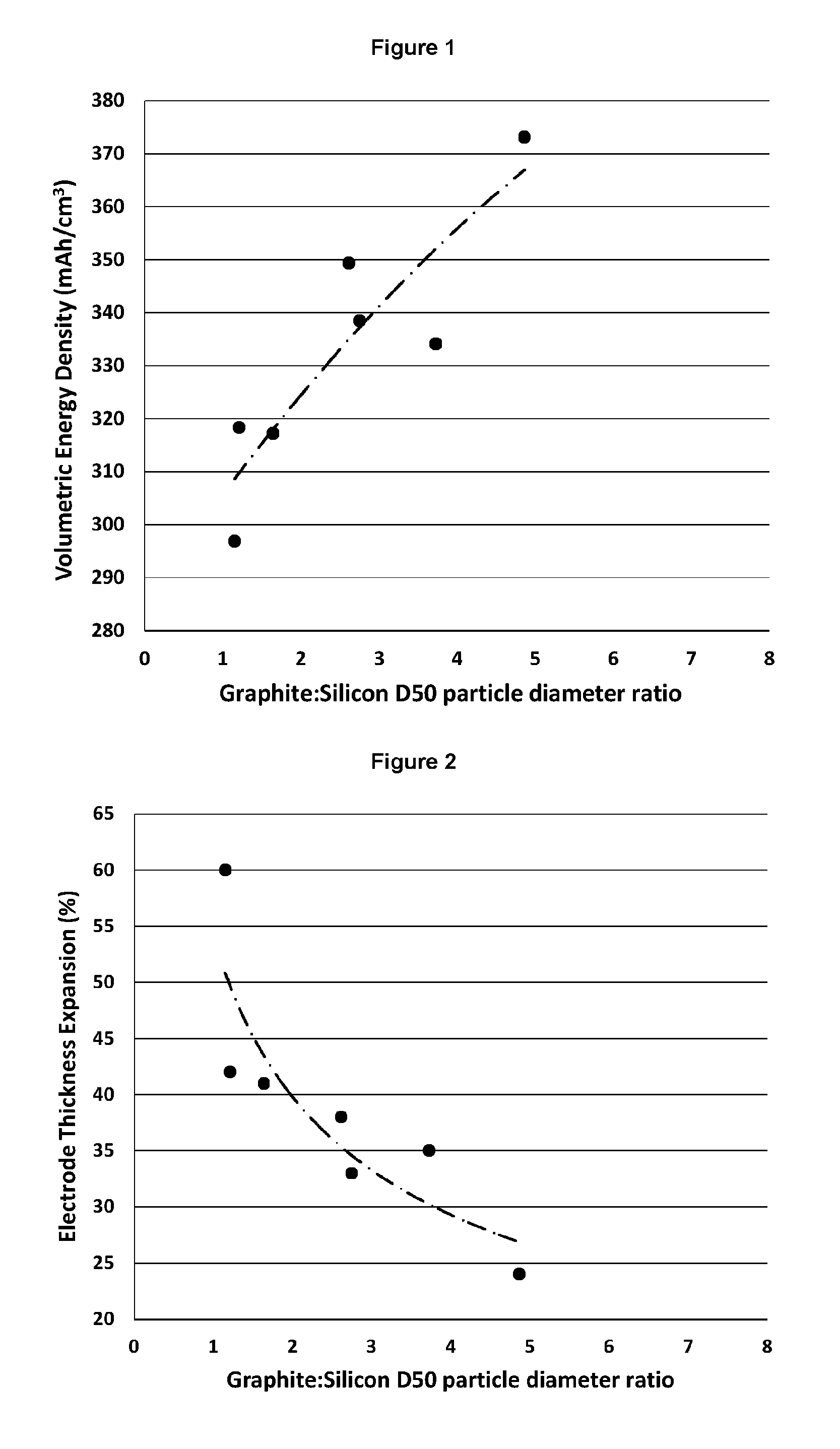
In a first aspect, the present invention provides an electrode for metal-ion battery, the electrode comprising an active layer in electrical contact with a current collector, wherein the active layer comprises: (i) a plurality of porous particles comprising an electroactive material selected from silicon, germanium, tin, aluminium and mixtures thereof, wherein the porous particles have a D.sub.50 particle diameter in the range of 0.5 to 18 .mu.m, and an intra-particle porosity in the range of from 30 to 90%; and (ii) a plurality of carbon particles selected from one or more of graphite, soft carbon and hard carbon and having a D.sub.50 particle diameter in the range of from 1 to 50 .mu.m; wherein the active layer comprises at least 50% by weight of the carbon particles (ii), and wherein the ratio of the D.sub.50 particle diameter of the carbon particles (ii) to the D.sub.50 particle diameter of the porous particles (i) is in the range of from 1.5 to 30.
It has been found that the hybrid electrodes of the invention have particularly advantageous properties for use in metal-ion batteries. By controlling the size ratio of the porous particles (i) and the carbon particles (ii), the porous particles (i) are advantageously located in the void spaces between the carbon particles (ii). Thus, the invention provides an increase in the capacity of the active layer compared to an active layer comprising only conventional carbon particles, while minimising any increase in the volume of the active layer. In addition, the porosity of the porous particles (i) is controlled within a range which permits at least some of the expansion of the electroactive material during insertion of metal ions to be accommodated by voids or spaces within the particle structure, thereby avoiding excessive outwards expansion of the porous particles (i), which could otherwise lead to deformation and delamination of the active layer of the electrode and/or to fracture of the porous particles. For instance, the outward volumetric expansion of the porous particles (i) defined herein on full lithiation is typically less than 80%, for example less than 50% or less than 25% of the expansion observed when a solid particle of the same volume is lithiated to its full capacity. At the same time, the porosity of the porous particles (i) is not so high that the volumetric capacity of the porous particles falls below useful limits. Furthermore, by maintaining the porosity of the porous particles (i) within the ranges set out herein, it is found that the porous particles are sufficiently robust to survive manufacture and incorporation into an electrode active layer without loss of structural integrity, particularly when electrode layers are calendered to produce a dense uniform layer, as is conventional in the art. Still further, the inventors have identified that the size of the porous particles enables the particles to be dispersed readily and without agglomeration in slurries, facilitating their incorporation into electrode materials that further comprise carbon particles. Effective dispersion of the porous particles is essential as an uneven distribution of the porous particles will lead to uneven charging and expansion of the active layer, leading to degradation of the active layer.
Silicon, germanium, tin and aluminium may be present in the porous particles (i) in combination with their oxides, for example due to the presence of a native oxide layer on the surfaces of the porous particles. As used herein, references to silicon, germanium, tin and aluminium shall be understood to include the oxides of silicon, germanium, tin and aluminium. Preferably, the oxides are present in an amount of no more than 30 wt %, more preferably no more than 25 wt %, more preferably no more than 20 wt %, more preferably no more than 15 wt %, more preferably no more than 10 wt %, more preferably no more than 5 wt %, for example no more than 4 wt %, no more than 3 wt %, no more than 2 wt % or no more than 1 wt %, based on the total amount of silicon, germanium, tin and aluminium and the oxides thereof.
The porous particles (i) preferably comprise at least 60 wt %, more preferably at least 70 wt %, more preferably at least 75 wt %, more preferably at least 80 wt %, and most preferably at least 85 wt % of the electroactive material. For example, the porous particles (i) may comprise at least 90 wt %, at least 95 wt %, at least 98 wt %, or at least 99 wt % of the electroactive material.
Preferred electroactive materials are silicon and tin. Thus, the porous particles (i) preferably comprise at least 60 wt %, more preferably at least 70 wt %, more preferably at least 75 wt %, more preferably at least 80 wt %, and most preferably at least 85 wt % of silicon or tin. For example, the porous particles (i) may comprise at least 90 wt %, at least 95 wt %, at least 98 wt %, or at least 99 wt % of silicon or tin.
A particularly preferred electroactive material is silicon. Thus, the porous particles (i) preferably comprise at least 60 wt %, more preferably at least 70 wt %, more preferably at least 75 wt %, more preferably at least 80 wt %, and most preferably at least 85 wt % of silicon. For example, the porous particles (i) may comprise at least 90 wt %, at least 95 wt %, at least 98 wt %, or at least 99 wt % of silicon.
The porous particles (i) may optionally comprise silicon or tin in combination with a minor amount of aluminium and/or germanium. For instance, the porous particles (i) may comprise at least 60 wt % silicon or tin and up to 40 wt % aluminium and/or germanium, more preferably at least 70 wt % silicon or tin and up to 30 wt % aluminium and/or germanium, more preferably at least 75 wt % silicon or tin and up to 25 wt % aluminium and/or germanium, more preferably at least 80 wt % silicon or tin and up to 20 wt % aluminium and/or germanium, more preferably at least 85 wt % silicon or tin and up to 15 wt % aluminium and/or germanium, more preferably at least 90 wt % silicon or tin and up to 10 wt % aluminium and/or germanium, and most preferably at least 95 wt % silicon or tin and up to 5 wt % aluminium and/or germanium.
Optionally, the porous particles (i) may comprise at least 0.01 wt % aluminium and/or germanium, at least 0.1 wt % aluminium and/or germanium, at least 0.5 wt % aluminium and/or germanium, at least 1 wt % aluminium, at least 2 wt % aluminium and/or germanium, or at least 3 wt % aluminium and/or germanium.
The porous particles (i) may optionally comprise a minor amount of one or more additional elements other than silicon, germanium, tin or aluminium. For instance, the porous particles (i) may comprise a minor amount of one or more additional elements selected from Sb, Cu, Mg, Zn, Mn, Cr, Co, Mo, Ni, Be, Zr, Fe, Na, Sr, P, Ru, Ag, Au and oxides thereof. Preferably the one or more additional elements, if present, are selected from one or more of Ni, Ag and Cu. The one or more additional elements may optionally be present in a total amount of no more than 40 wt %, more preferably no more than 30 wt %, more preferably no more than 25 wt %, more preferably no more than 20 wt %, more preferably no more than 15 wt %, more preferably no more than 10 wt %, and most preferably no more than 5 wt %, based on the total weight of the particulate material. Optionally, the one or more additional elements may be present in a total amount of at least 0.01 wt %, at least 0.05 wt %, at least 0.1 wt %, at least 0.2 wt %, at least 0.5 wt %, at least 1 wt %, at least 2 wt %, or at least 3 wt %, based on the total weight of the particulate material.
The porous particles (i) have a D.sub.50 particle diameter in the range of from 0.5 .mu.m to 18 .mu.m. Preferably, the D.sub.50 particle diameter of the porous particles (i) is at least 0.8 .mu.m, at least 1 .mu.m at least 1.5 .mu.m, at least 2 .mu.m, at least 2.5 .mu.m, or at least 3 .mu.m. Preferably, the D.sub.50 particle diameter of the porous particles (i) is no more than 15 .mu.m, no more than 12 .mu.m, no more than 10 .mu.m, no more than 8 .mu.m, no more than 7 .mu.m, no more than 6.5 .mu.m, no more than 6 .mu.m, no more than 5.5 .mu.m, no more than 5 .mu.m, no more than 4.5 .mu.m, no more than 4 .mu.m, or no more than 3.5 .mu.m. For example, the porous particles (i) may have a D.sub.50 particle diameter in the range of from 1 .mu.m to 15 .mu.m, 1 .mu.m to 12 .mu.m, 1 .mu.m to 10 .mu.m, or 1 .mu.m to 7 .mu.m.
The D.sub.10 particle diameter of the porous particles (i) is preferably at least 0.1 .mu.m, at least 0.2 .mu.m, at least 0.3 .mu.m at least 0.4 .mu.m, at least 0.5 .mu.m, at least 0.6 .mu.m at least 0.8 .mu.m, at least 1 .mu.m, at least 2 .mu.m, or at least 3 .mu.m. Porous particles (i) having a D.sub.10 particle diameter of at least 0.5 .mu.m are particularly preferred as the potential for undesirable agglomeration of sub-micron sized particles is reduced, resulting in improved dispersibility of the particulate material in slurries.
When the D.sub.50 particle diameter of the porous particles (i) is at least 1 .mu.m, the D.sub.10 particle diameter is preferably at least 0.5 .mu.m, more preferably at least 1 .mu.m. When the D.sub.50 particle diameter of the porous particles (i) is at least 1.5 .mu.m, the D.sub.10 particle diameter is preferably at least 0.8 .mu.m, more preferably at least 1 .mu.m. When the D.sub.50 particle diameter of the porous particles (i) is at least 2 .mu.m, the D.sub.10 particle diameter is preferably at least 1 .mu.m and still more preferably at least 1.5 .mu.m.
The D.sub.90 particle diameter of the porous particles (i) is preferably no more than 30 .mu.m, no more than 20 .mu.m, no more than 15 .mu.m, no more than 12 .mu.m, no more than 10 .mu.m, or no more than 8 .mu.m.
When the D.sub.50 particle diameter of the porous particles (i) is no more than 12 .mu.m, the D.sub.90 particle diameter is preferably no more than 20 .mu.m, more preferably no more than 15 .mu.m. When the D.sub.50 particle diameter of the porous particles (i) is no more than 10 .mu.m, the D.sub.90 particle diameter is preferably no more than 15 .mu.m, more preferably no more than 12 .mu.m. When the D.sub.50 particle diameter of the porous particles (i) is no more than 6 .mu.m, the D.sub.90 particle diameter is preferably no more than 10 .mu.m, more preferably no more than 8 .mu.m. When the D.sub.50 particle diameter of the porous particles (i) is no more than 5 .mu.m, the D.sub.90 particle diameter is preferably no more than 7.5 .mu.m, more preferably no more than 7 .mu.m. When the D.sub.50 particle diameter of the porous particles (i) is no more than 4 .mu.m, the D.sub.90 particle diameter is preferably no more than 6 .mu.m, more preferably no more than 5.5 .mu.m.
The D.sub.99 particle diameter of the porous particles (i) is preferably no more than 40 .mu.m, no more than 30 .mu.m, no more than 25 .mu.m, no more than 20 .mu.m, no more than 15 .mu.m, or no more than 12 .mu.m.
When the D.sub.50 particle diameter of the porous particles (i) is no more than 12 .mu.m, the D.sub.99 particle diameter is preferably no more than 30 .mu.m, more preferably no more than 20 .mu.m. When the D.sub.50 particle diameter of the porous particles (i) is no more than 10 .mu.m, the D.sub.99 particle diameter is preferably no more than 25 .mu.m, more preferably no more than 15 .mu.m. When the D.sub.50 particle diameter of the porous particles (i) is no more than 6 .mu.m, the D.sub.99 particle diameter is preferably no more than 15 .mu.m, more preferably no more than 12 .mu.m. When the D.sub.50 particle diameter of the porous particles (i) is no more than 5 .mu.m, the D.sub.99 particle diameter is preferably no more than 12 .mu.m, more preferably no more than 9 .mu.m.
Preferably, the porous particles (i) have a narrow size distribution span. For instance, the particle size distribution span (defined as (D.sub.90-D.sub.10)/D.sub.50) is preferably 5 or less, 4 or less, 3 or less, 2 or less or 1.5 or less. By maintaining a narrow size distribution span, the concentration of particles in the size range found by the inventors to be most favourable for use in electrodes is maximised.
For the avoidance of doubt, the term "particle diameter" as used herein refers to the equivalent spherical diameter (esd), i.e. the diameter of a sphere having the same volume as a given particle, wherein the particle volume is understood to include the volume of the intra-particle pores. The terms "D.sub.50" and "D.sub.50 particle diameter" as used herein refer to the volume-based median particle diameter, i.e. the diameter below which 50% by volume of the particle population is found. The terms "D.sub.10" and "D.sub.10 particle diameter" as used herein refer to the 10th percentile volume-based median particle diameter, i.e. the diameter below which 10% by volume of the particle population is found. The terms "D.sub.90" and "D.sub.90 particle diameter" as used herein refer to the 90th percentile volume-based median particle diameter, i.e. the diameter below which 90% by volume of the particle population is found. The terms "D.sub.99" and "D.sub.99 particle diameter" as used herein refer to the 99th percentile volume-based median particle diameter, i.e. the diameter below which 99% by volume of the particle population is found.
Particle diameters and particle size distributions can be determined by routine laser diffraction techniques. Laser diffraction relies on the principle that a particle will scatter light at an angle that varies depending on the size the particle and a collection of particles will produce a pattern of scattered light defined by intensity and angle that can be correlated to a particle size distribution. A number of laser diffraction instruments are commercially available for the rapid and reliable determination of particle size distributions. Unless stated otherwise, particle size distribution measurements as specified or reported herein are as measured by the conventional Malvern Mastersizer 2000 particle size analyzer from Malvern Instruments. The Malvern Mastersizer 2000 particle size analyzer operates by projecting a helium-neon gas laser beam through a transparent cell containing the particles of interest suspended in an aqueous solution. Light rays which strike the particles are scattered through angles which are inversely proportional to the particle size and a photodetector array measures the intensity of light at several predetermined angles and the measured intensities at different angles are processed by a computer using standard theoretical principles to determine the particle size distribution. Laser diffraction values as reported herein are obtained using a wet dispersion of the particles in distilled water. The particle refractive index is taken to be 3.50 and the dispersant index is taken to be 1.330. Particle size distributions are calculated using the Mie scattering model.
The average aspect ratio of the porous particles (i) is preferably less than 3:1, more preferably no more than 2.5:1, more preferably no more than 2:1, more preferably no more than 1.8:1, more preferably no more than 1.6:1, more preferably no more than 1.4:1 and most preferably no more than 1.2:1. As used herein, the term "aspect ratio" refers to the ratio of the longest dimension to the shortest dimension of a two-dimensional particle projection. The term "average aspect ratio" refers to a number-weighted mean average of the aspect ratios of the individual particles in the particle population.
The porous particles (i) are preferably spheroidal in shape. Spheroidal particles as defined herein may include both spherical and ellipsoidal particles and the shape of the porous particles (i) may suitably be defined by reference to both the average aspect ratio and the average sphericity of the porous particles. Spheroidal particles are found to be particularly well-suited to dispersion in slurries without the formation of agglomerates and are readily located in the void spaces (interstices) between the carbon particles in electrode layers. The sphericity of an object is conventionally defined as the ratio of the surface area of a sphere to the surface area of the object, wherein the object and the sphere have identical volume. However, in practice it is difficult to measure the surface area and volume of individual particles at the micron scale. However, it is possible to obtain highly accurate two-dimensional projections of micron scale particles by scanning electron microscopy (SEM) and by dynamic image analysis, in which a digital camera is used to record the shadow projected by a particle. The term "sphericity" as used herein shall be understood as the ratio of the area of the particle projection to the area of a circle, wherein the particle projection and circle have identical circumference. Thus, for an individual particle, the sphericity S may be defined as:
.pi. ##EQU00001## wherein A.sub.m is the measured area of the particle projection and C.sub.m is the measured circumference of the particle projection. The average sphericity S.sub.av of a population of particles as used herein is defined as:
.times..times..pi. ##EQU00002## wherein n represents the number of particles in the population.
As used herein, the term "spheroidal" as applied to the porous particles (i) shall be understood to refer to a material having an average sphericity of at least 0.70. Preferably, the porous particles (i) have an average sphericity of at least 0.85, more preferably at least 0.90, more preferably at least 0.92, more preferably at least 0.93, more preferably at least 0.94, more preferably at least 0.95, more preferably at least 0.96, more preferably at least 0.97, more preferably at least 0.98 and most preferably at least 0.99.
It will be understood that the circumference and area of a two-dimensional particle projection will depend on the orientation of the particle in the case of any particle which is not perfectly spheroidal. However, the effect of particle orientation may be offset by reporting sphericity and aspect ratios as average values obtained from a plurality of particles having random orientation.
A number of SEM and dynamic image analysis instruments are commercially available, allowing the sphericity and aspect ratio of a particulate material to be determined rapidly and reliably. Unless stated otherwise, sphericity values as specified or reported herein are as measured by a CamSizer XT particle analyzer from Retsch Technology GmbH. The CamSizer XT is a dynamic image analysis instrument which is capable of obtaining highly accurate distributions of the size and shape for particulate materials in sample volumes of from 100 mg to 100 g, allowing properties such as average sphericity and aspect ratios to be calculated directly by the instrument.
As used herein, the term "porous particle" shall be understood as referring to a particle comprising a plurality of pores, voids or channels within a particle structure. The term "porous particle" shall be understood in particular to include particles comprising a random or ordered network of linear, branched or layered elongate structural elements, wherein interconnected void spaces or channels are defined between the elongate structural elements of the network, the elongate structural elements suitably including linear, branched or layered fibres, tubes, wires, pillars, rods, ribbons, plates, walls or flakes. Preferably the porous particles (i) have a substantially open porous structure such that substantially all of the pore volume of the porous particles is accessible to a fluid from the exterior of the particle, for instance to a gas or to an electrolyte. By a substantially open porous structure, it is meant that at least 90%, preferably at least 95%, preferably at least 98%, preferably at least 99% of the pore volume of the porous particles is accessible from the exterior of the particles.
The porous particles (i) may be distinguished in some embodiments by a specific microstructure or architecture of the structural elements that constitute the porous particles. Preferably, the porous particles (i) comprise a network of interconnected irregular elongate structural elements comprising the electroactive material which may be described as acicular, flake-like, dendritic, or coral-like. This particle architecture is associated with an interconnected network of pores, preferably with a substantially even distribution of the pores throughout the particle.
Intra-particle porosity is defined herein as the ratio of the volume of pores within a particle to the total volume of the particle. Inter-particle porosity is the volume of pores between discrete particles and is a function both of the size and shape of the individual particles and of the packing density of the particles in the active layer.
The intra-particle porosity of the porous particles is preferably in the range of 35 to 90%, and more preferably in the range of 40 to 90%.
The intra-particle porosity of the porous particles (i) is preferably at least 45%, and may be at least 50%, at least 60%, or at least 70%. The intra-particle porosity of the porous particles (i) is preferably no more than 89%, more preferably no more than 88%, more preferably no more than 87%, more preferably no more than 86%, and most preferably no more than 85%. For example, the intra-particle porosity of the porous particles (i) may be no more than 80%, no more than 75%, no more than 70%, no more than 65%, no more than 60%, no more than 55% or no more than 50%.
Where the porous particles (i) are prepared by removal of an unwanted component from a starting material, e.g. by leaching of an alloy as discussed in further detail below, the intra-particle porosity can suitably be determined by determining the elemental composition of the particles before and after leaching and calculating the volume of material that is removed.
More preferably, the intra-particle porosity of the porous particles (i) may be measured by mercury porosimetry. Mercury porosimetry is a technique that characterises the porosity of a material by applying varying levels of pressure to a sample of the material immersed in mercury. The pressure required to intrude mercury into the pores of the sample is inversely proportional to the size of the pores. More specifically, mercury porosimetry is based on the capillary law governing liquid penetration into small pores. This law, in the case of a non-wetting liquid such as mercury, is expressed by the Washburn equation: D=(1/P)4.gamma.cos .phi. wherein D is pore diameter, P is the applied pressure, .gamma. is the surface tension, and .omega. is the contact angle between the liquid and the sample. The volume of mercury penetrating the pores of the sample is measured directly as a function of the applied pressure. As pressure increases during an analysis, pore size is calculated for each pressure point and the corresponding volume of mercury required to fill these pores is measured. These measurements, taken over a range of pressures, give the pore volume versus pore diameter distribution for the sample material. The Washburn equation assumes that all pores are cylindrical. While true cylindrical pores are rarely encountered in real materials, this assumption provides sufficiently useful representation of the pore structure for most materials. For the avoidance of doubt, references herein to pore diameter shall be understood as referring to the equivalent cylindrical dimensions as determined by mercury porosimetry. Values obtained by mercury porosimetry as reported herein are obtained in accordance with ASTM UOP574-11, with the surface tension .gamma. taken to be 480 mN/m and the contact angle .omega. taken to be 140.degree. for mercury at room temperature. The density of mercury is taken to be 13.5462 g/cm.sup.3 at room temperature.
For a sample in the form of a powder of porous particles, the total pore volume of the sample is the sum of intra-particle and inter-particle pores. This gives rise to an at least bimodal pore diameter distribution curve in a mercury porosimetry analysis, comprising a set of one or more peaks at lower pore sizes relating to the intra-particle pore diameter distribution and a set of one or more peaks at larger pore sizes relating to the inter-particle pore diameter distribution. From the pore diameter distribution curve, the lowest point between the two sets of peaks indicates the diameter at which the intra-particle and inter-particle pore volumes can be separated. The pore volume at diameters greater than this is assumed to be the pore volume associated with inter-particle pores. The total pore volume minus the inter-particle pore volume gives the intra-particle pore volume from which the intra-particle porosity can be calculated.
Porosimetry such as mercury porosimetry may also be used to measure the inter-particle porosity of the active layer of the electrode comprising the porous particles and carbon particles.
A number of high precision mercury porosimetry instruments are commercially available, such as the AutoPore IV series of automated mercury porosimeters available from Micromeritics Instrument Corporation, USA. For a complete review of mercury porosimetry reference may be made to P. A. Webb and C. Orr in "Analytical Methods in Fine Particle Technology, 1997, Micromeritics Instrument Corporation, ISBN 0-9656783-0.
It will be appreciated that mercury porosimetry and other intrusion techniques are effective only to determine the pore volume of pores that are accessible to mercury (or another fluid) from the exterior of the porous particles to be measured. As noted above, substantially all of the pore volume of the porous particles (i) is accessible from the exterior of the particles, and thus porosity measurements by mercury porosimetry will generally be equivalent to the entire pore volume of the particles. Nonetheless, for the avoidance of doubt, intra-particle porosity and electrode inter-particle porosity values as specified or reported herein shall be understood as referring to the volume of open pores, i.e. pores that are accessible to a fluid from the exterior of the particles or electrode active layer. Fully enclosed pores which cannot be identified by mercury porosimetry shall not be taken into account herein when specifying or reporting intra-particle porosity.
The porous particles (i) preferably have an intra-particle pore diameter distribution having at least one peak at a pore size less than 350 nm, more preferably less than 300 nm, more preferably less than 250 nm, and most preferably less than 200 nm, as determined by mercury porosimetry. Preferably, the pore diameter distribution has at least one peak at a pore size of more than 50 nm, more preferably more than 60 nm, and most preferably more than 80 nm, as determined by mercury porosimetry.
The porous particles (i) are therefore preferably characterised not only by the overall porosity of the porous particles, but also by the way that the porosity is distributed in the particles. Preferably, the porosity is associated with a pore diameter distribution which ensures that the architecture of the electroactive material in the porous particles (i) is neither so fine as to be degraded during processing into electrode layers nor so large as to undergo unacceptable stress during charging and discharging of the electroactive material. Thus, the porous particles (i) are sufficiently robust to survive manufacture and incorporation into an anode layer without loss of structural integrity, particularly when anode layers are calendered to produce a dense uniform layer as is conventional in the art, while also providing reversible capacity over multiple charge-discharge cycles at a level which is commercially acceptable.
The porous particles preferably comprise networks of fine structural elements having an aspect ratio of at least 2:1 and more preferably at least 5:1. A high aspect ratio of the structural elements provides a high number of interconnections between the structural elements constituting the porous particles for electrical continuity.
The thickness of the structural elements constituting the porous particles (i) is an important parameter in relation to the ability of the electroactive material to reversibly intercalate and release metal ions. Structural elements which are too thin may result in excessive first cycle loss due to excessively high BET surface area the resulting formation of an SEI layer. However, structural elements which are too thick are placed under excessive stress during insertion of metal ions and also impede the insertion of metal ions into the bulk of the silicon material. The invention aims to provide an optimum balance of these competing factors due to the presence of structural elements of optimised size and proportions. Thus, the porous particles preferably comprise structural elements having a smallest dimension less than 300 nm, preferably less than 200 nm, more preferably less than 150 nm, and a largest dimension at least twice, and preferably at least five times the smallest dimension. The smallest dimension is preferably at least 10 nm, more preferably at least 20 nm, and most preferably at least 30 nm.
The porous particles (i) may be primary or secondary particles, and are preferably discrete primary particles. However, it is not excluded that the porous silicon-containing particles may comprise porous primary particles which are incorporated into secondary particles.
For the avoidance of doubt, the term "primary particle" is used herein in its conventional meaning, i.e. to refer to the individual fragments of matter in a particulate material (IUPAC defines a "primary particle" as the "smallest discrete identifiable entity" in a particulate material). Primary particles may be distinguished from secondary particles, which are particles assembled from a plurality of primary particles and held together either by weak forces of adhesion or cohesion in the case of agglomerates, or by strong atomic or molecular forces in the case of aggregates. The primary particles forming secondary particles retain an individual identity, and it will therefore be understood that secondary particles comprising only pores between the constituent non-porous primary particles can readily be distinguished from primary particles having intrinsic porosity.
The porous particles (i) preferably have a BET surface area of less than 300 m.sup.2/g, less than 250 m.sup.2/g, less than 200 m.sup.2/g, less than 150 m.sup.2/g, less than 120 m.sup.2/g, of less than 100 m.sup.2/g, or less than 80 m.sup.2/g. Suitably, the BET surface area may be at least 10 m.sup.2/g, at least 15 m.sup.2/g, at least 20 m.sup.2/g, or at least 50 m.sup.2/g. The term "BET surface area" as used herein should be taken to refer to the surface area per unit mass calculated from a measurement of the physical adsorption of gas molecules on a solid surface, using the Brunauer-Emmett-Teller theory, in accordance with ASTM B922/10.
Control of the BET surface area of electroactive material is an important consideration in the design of electrodes for metal ion batteries. A BET surface area which is too low results in unacceptably low charging rate and capacity due to the inaccessibility of the bulk of the electroactive material to metal ions in the surrounding electrolyte. However, a very high BET surface area is also known to be disadvantageous due to the formation of a solid electrolyte interphase (SEI) layer at the anode surface during the first charge-discharge cycle of the battery. SEI layers are formed due to reaction of the electrolyte at the surface of electroactive materials and can consume significant amounts of metal ions from the electrolyte, thus depleting the capacity of the battery in subsequent charge-discharge cycles. While previous teaching in the art focuses on an optimum BET surface area below about 10 m.sup.2/g, the present inventors have found that a much wider BET range can be tolerated when using the particulate material of the invention as an electroactive material.
The electroactive material containing structural elements constituting the porous particles (i) preferably comprise amorphous or nanocrystalline electroactive material having a crystallite size of less than 100 nm, preferably less than 60 nm. The structural elements may comprise a mixture of amorphous and nanocrystalline electroactive material. The crystallite size may be determined by X-ray diffraction spectrometry analysis using an X-ray wavelength of 1.5456 nm. The crystallite size is calculated using the Scherrer equation from a 2e XRD scan, where the crystallite size d=K.lamda./(BCos .theta..sub.B), the shape constant K is taken to be 0.94, the wavelength .lamda. is 1.5456 nm, .theta..sub.B is the Bragg angle associated with the 220 silicon peak, and B is the full width half maximum (FWHM) of that peak. Suitably the crystallite size is at least 10 nm.
The porous particles (i) may suitably be obtained by processes in which unwanted material is removed from a particulate starting material comprising the electroactive material. Removal of unwanted material may create or expose the electroactive material structures defining the porous particles. For example, this may involve the removal/reduction of oxide components from a silicon, germanium, tin and/or aluminium structure, the etching of bulk silicon, germanium, tin and/or aluminium particles, or the leaching of a metal matrix from alloy particles containing electroactive material structures in a metal matrix.
The porous particles (i) may be formed by etching electroactive material to form pores, voids or channels within the electroactive material. Example etching processes include stain etching, metal-assisted chemical etching and electrochemical etching. The porous particle (ii) may be formed by reduction of the oxides of electroactive material to form porous electroactive material. For example, porous silicon particles may be formed by the magnesiothermic reduction of silica or silicon monoxide.
The porous particles (i) may be formed from a particulate or bulk starting material and the process may comprise fragmentation, fracturing or milling of the porosified starting material to form the porous particles (i).
The porous particles (i) are preferably obtained by a process comprising leaching particles of an alloy comprising silicon and/or germanium structures in a metal matrix. This process relies on the observation that a network of crystalline silicon and/or germanium structures is precipitated within an alloy matrix when certain alloys containing these elements are cooled from the molten state.
Suitably, the alloys comprise matrix metals in which the solubility of silicon and/or germanium is low and/or in which the formation of intermetallics on cooling is negligible or non-existent. Leaching of the metals constituting the metal matrix exposes the network of silicon and/or germanium structures. Thus, leaching particles of an alloy comprising silicon and/or germanium provides a suitable route to the porous particles defined above.
The porous particles (i) may comprise a plurality of electroactive material-containing fragments which are agglomerated or otherwise assembled or connected together to form the porous particles (i).
The carbon particles (ii) are preferably graphite particles. The graphite particles may comprise synthetic or natural graphite. Preferably, the graphite has a maximum specific capacity of at least 300 mAh/g, for example from 300 to 360 mAh/g or from 300 to 340 mAh/g.
The carbon particles (ii) have a D.sub.50 particle diameter in the range of from 1 to 50 .mu.m. Preferably the D.sub.50 particle diameter of the carbon particles (ii) is at least 2 .mu.m, at least 5 .mu.m, at least 7 .mu.m, at least 8 .mu.m, at least 10 .mu.m, at least 12 .mu.m, or at least 15 .mu.m. Preferably, the D.sub.50 particle diameter of the carbon particles (ii) is no more than 45 .mu.m, no more than 40 .mu.m, no more than 35 .mu.m, no more than 30 .mu.m, or no more than 25 .mu.m. Where the D.sub.50 particle sizes of the porous particles (i) and the carbon particles (ii) are within the preferred ranges disclosed herein, the porous particles (i) are advantageously able to occupy void space between the carbon particles (ii), particularly when one or preferably both of the porous particles (i) and carbon particles (ii) are spheroidal in shape.
The carbon particles (ii) may thus be in the form of spheroidal particles having an average sphericity S.sub.av of at least 0.70, preferably at least 0.85, more preferably at least 0.90, more preferably at least 0.92, more preferably at least 0.93, more preferably at least 0.94, and most preferably at least 0.95.
The carbon particles (ii) may have an average aspect ratio of less than 3:1, preferably no more than 2.5:1, more preferably no more than 2:1, more preferably no more than 1.8:1, more preferably no more than 1.6:1, more preferably no more than 1.4:1 and most preferably no more than 1.2:1.
In preferred embodiments, the carbon particles (ii) are selected from spheroidal graphite particles having a D.sub.50 particle diameter in the range of from 5 to 50 .mu.m. More preferably, the carbon particles (ii) are selected from spheroidal graphite particles having a D.sub.50 particle diameter in the range of from 8 to 25 .mu.m. Most preferably, the carbon particles (ii) are selected from spheroidal graphite particles having a D.sub.50 particle diameter in the range of from 8 to 25 .mu.m and the porous particles (i) are selected from porous spheroidal particles comprising silicon, as described above.
The active layer of the electrode preferably comprises from 60 to 95 wt %, preferably from 70 to 95 wt %, and most preferably from 80 to 95 wt % of the carbon particles (ii).
The active layer of the electrode suitably comprises from 1 to 30 wt % of the porous particles (i). Preferably, the active layer comprises at least 2 wt %, more preferably at least 5 wt % and most preferably at least 8 wt % of the porous particles (i). Preferably the active layer comprises no more than 25 wt %, more preferably no more than 20 wt %, and most preferably no more than 15 wt % of the porous particles (i).
The ratio of the D.sub.50 particle diameter of the carbon particles (ii) to the D.sub.50 particle diameter of the porous particles (i) is preferably at least 2, at least 2.5, at least 3, at least 3.5, or at least 4. The ratio of the D.sub.50 particle diameter of the carbon particles (ii) to the D.sub.50 particle diameter of the porous particles (i) is preferably no more than 25, no more than 20, no more than 15, or no more than 10.
The active layer suitably has an inter-particle porosity of no more than 30%, preferably no more than 25%, and most preferably no more than 20%. Preferably, the inter-particle porosity of the active layer is at least 2%, more preferably at least 5%, and most preferably at least 10%. The inter-particle porosity of the active layer is suitably determined by mercury porosimetry as described above. It is found that the combination of the porous particles (i) and the carbon particles (ii) together with inter-particle porosity in the ranges set out herein facilitates homogeneous wetting of the active materials by an electrolyte without an excessive reduction in the volumetric energy density of the active layer. Accordingly, the charge and discharge rates of the active layer are maintained at acceptable levels and irreversible loss of metal ions is reduced.
The active layer of the electrode in a dry, uncharged state, preferably has a density in the range of from 1 to 2 g/cm.sup.3. Preferably, the active layer of the electrode has a density in the range of from 1.05 g/cm.sup.3 to 1.95 g/cm.sup.3, from 1.1 g/cm.sup.3 to 1.9 g/cm.sup.3, or from 1.15 g/cm.sup.3 to 1.9 g/cm.sup.3. Optionally, the active layer of the electrode has a density of at least 1.2 g/cm.sup.3, at least 1.25 g/cm.sup.3, at least 1.3 g/cm.sup.3, at least 1.35 g/cm.sup.3, or at least 1.4 g/cm.sup.3. Optionally, the active layer of the electrode has a density of no more than 1.85 g/cm.sup.3, no more than 1.8 g/cm.sup.3, or no more than 1.75 g/cm.sup.3. For instance, the active layer of the electrode may have a density from 1.05 g/cm.sup.3 to 1.1 g/cm.sup.3, from 1.1 g/cm.sup.3 to 1.15 g/cm.sup.3, from 1.15 g/cm.sup.3 to 1.2 g/cm.sup.3, from 1.2 g/cm.sup.3 to 1.25 g/cm.sup.3, from 1.25 g/cm.sup.3 to 1.3 g/cm.sup.3, from 1.3 g/cm.sup.3 to 1.35 g/cm.sup.3, from 1.35 g/cm.sup.3 to 1.4 g/cm.sup.3, from 1.4 g/cm.sup.3 to 1.45 g/cm.sup.3, from 1.45 g/cm.sup.3 to 1.5 g/cm.sup.3, from 1.5 g/cm.sup.3 to 1.55 g/cm.sup.3, from 1.55 g/cm.sup.3 to 1.6 g/cm.sup.3, from 1.6 g/cm.sup.3 to 1.65 g/cm.sup.3, from 1.65 g/cm.sup.3 to 1.7 g/cm.sup.3, from 1.7 g/cm.sup.3 to 1.75 g/cm.sup.3, from 1.75 g/cm.sup.3 to 1.8 g/cm.sup.3, from 1.8 g/cm.sup.3 to 1.85 g/cm.sup.3, from 1.85 g/cm.sup.3 to 1.9 g/cm.sup.3, or from 1.9 g/cm.sup.3 to 1.95 g/cm.sup.3.
The density of the active layer may suitably be measured by measuring the mass and thickness of an electrode of known dimensions before and after removal of the active layer from the electrode current collector.
It will be understood that a high density active layer would be expected in theory to provide a high energy density. However, if the density of the active layer is too high, then the active layer does not have sufficient porosity to allow the electrolyte to permeate through the active layer, which results in uneven lithiation of the active layer leading to cracking of the active layer and high ionic resistance. With solid silicon particles, high density electrode layers can be obtained, but repeated metallation and demetallation of the silicon leads to increased expansion of the electrode layer and electrical disconnection of particles. Significant electrode expansion may also place a strain on other electrode components.
Conventional graphite only electrodes have a typical coating density in the range of from 1.8 to 2.3 g/cm.sup.3. However, the present inventors have identified that for the electrodes of the invention, optimum performance is obtained at an active layer density which is somewhat lower, whilst still achieving higher volumetric energy densities at full charge than conventional electrodes. The reduced density of the active layer compared to graphite electrodes is compensated by the significantly higher volumetric capacity of materials such as silicon. Accordingly, electrodes having active layers having density within the preferred ranges identified above are found to provide an optimum balance between volumetric energy density, electrical connectivity and low electrode expansion, whilst still maintaining good penetration of the electrolyte into the active layer.
Suitably, the electrode of the invention has an active layer with a volumetric energy density at first full charge of at least 450 mAh/cm.sup.3, suitably at least 575 mAh/cm.sup.3, suitably at least 600 mAh/cm.sup.3, suitably at least 650 mAh/cm.sup.3.
The electrode of the invention may also be characterised by cutting a cross-section through the active layer and carrying out image analysis of the active layer cross-section using SEM imaging. An electrode sample is sectioned by cutting in a direction transverse to the planar surface of the active layer and then imaged in an SEM to provide cross-sectional images of the components and void spaces within the active layer. Digital image analysis software such as the open source ImageJ software may be used to identify and distinguish between the porous particle areal sections and carbon particle areal sections and to compute the Feret diameters and sphericity of each particle. The total area of voids and pore spaces within the cross-section may also be calculated. Suitably at least two or more cross sections of the electrode should be made, parallel to each other and equally spaced apart. Suitably at least 3, preferably at least 5, and more preferably at least 10 cross sections are measured. The spacing between each cross section is suitably at least 20 .mu.m. The average Feret diameters and average sphericity values are calculated as an average of the value for all particles being measured across the plurality of cross-sections.
For example, the electrode of the invention may be characterised by reference to the average maximum Feret diameter of the porous particles (i) observable in the active layer cross section (referred to herein as F.sub.maxPP). Suitably, F.sub.maxPP is in the range of from 0.5 to 18 .mu.m. Optionally, F.sub.maxPP may be at least 0.8 .mu.m, at least 1 .mu.m, at least 1.5 .mu.m, at least 2 .mu.m, at least 2.5 .mu.m, or at least 3 .mu.m. Optionally, F.sub.maxPP may be no more than 15 .mu.m, no more than 12 .mu.m, no more than 10 .mu.m, no more than 8 .mu.m, no more than 7 .mu.m, no more than 6.5 .mu.m, no more than 6 .mu.m, no more than 5.5 .mu.m, no more than 5 .mu.m, no more than 4.5 .mu.m, no more than 4 .mu.m, or no more than 3.5 .mu.m.
The electrode of the invention may be characterised by reference to the average minimum Feret diameter of the porous particles (i) observable in the active layer cross (referred to herein as F.sub.minPP). Suitably, F.sub.minPP may be at least 0.1 .mu.m, at least 0.2 .mu.m, at least 0.3 .mu.m, at least 0.4 .mu.m, at least 0.5 .mu.m, at least 0.6 .mu.m, at least 0.8 .mu.m or at least 1 .mu.m. Optionally, F.sub.minPP is no more than 15 .mu.m, no more than 12 .mu.m, no more than 10 .mu.m, no more than 8 .mu.m, no more than 6 .mu.m, no more than 5 .mu.m, no more than 4.5 .mu.m, no more than 4 .mu.m, no more than 3.5 .mu.m, no more than 3 .mu.m, or no more than 2.5 .mu.m. Optionally, the value of F.sub.minPP may be at least 50% of the value of F.sub.maxPP, for example at least 60%, at least 70%, at least 80%, at least 90% or at least 95% of the value of F.sub.maxPP.
For the avoidance of doubt, the term "maximum Feret diameter" as used herein refers to the maximum distance between a pair of parallel lines tangent to the two-dimensional projection of a particle. The term "average maximum Feret diameter" or "F.sub.max" as used herein refers to the mean number average maximum Feret diameter. Likewise, the term "minimum Feret" diameter as used herein refers to the minimum distance between a pair of parallel lines tangent to the two-dimensional projection of a particle. The term "average minimum Feret diameter" or "F.sub.min" as used herein refers to the mean number average minimum Feret diameter as calculated from a minimum of 3, preferably 5 and most preferably 10 electrode active layer cross-sections.
The average maximum Feret diameter of the carbon particles (ii) observable in the active layer cross section (referred to herein as F.sub.maxC) is suitably in the range of from 1 to 50 .mu.m. Preferably F.sub.maxC is at least 2 .mu.m, at least 5 .mu.m, at least 7 .mu.m, at least 8 .mu.m, at least 10 .mu.m, at least 12 .mu.m, or at least 15 .mu.m. Preferably, F.sub.maxC is no more than 45 .mu.m, no more than 40 .mu.m, no more than 35 .mu.m, no more than 30 .mu.m, or no more than 25 .mu.m.
The average minimum Feret diameter of the carbon particles (ii) observable in the active layer cross section (referred to herein as F.sub.minC) is suitably at least 0.5 .mu.m, at least 1 .mu.m, at least 2 .mu.m, at least 5 .mu.m, at least 8 .mu.m, at least 10 .mu.m, at least 12 .mu.m, or at least 15 .mu.m. Optionally, F.sub.minC is no more than 40 .mu.m, no more than 35 .mu.m, no more than 30 .mu.m, or no more than 20 .mu.m. Optionally, the value of F.sub.minC may be at least 50% of the value of F.sub.maxC, for example at least 60%, at least 70%, at least 80%, at least 90% or at least 95% of the value of F.sub.maxC.
The active layer of the electrode of the invention may also be defined by reference to the average percentage of the cross sectional area of the active layer that is occupied by the porous particles (i) including their intra-particle pores, the carbon particles (ii) and the inter-particle pores as a percentage of the total area occupied by the active layer in the cross section. Suitably, the average percent cross-sectional area of the active layer occupied by the porous particles (i) including intra-particle pores, the carbon particles (ii) and the inter-particle pores may be measured by SEM imaging and is reported herein as a mean average of at least three cross-sections of the active layer having a cross-sectional area defined by the thickness of the active layer and a transverse width of at least 100 .mu.m.
The percent average cross-sectional area of the active layer occupied by the porous particles (i) including their intra-particle pores is preferably in the range of from 1% to 25%, more preferably from 2% to 20%, more preferably from 5% to 20% and most preferably from 5% to 15%.
The percent average cross-sectional area of the active layer occupied by the carbon particles (ii) is preferably in the range of from 40% to 85%, more preferably from 45% to 85%, more preferably from 45% to 80% and most preferably from 45% to 75%.
The percent average cross-sectional area of the active layer occupied by the inter-particle pores of the active layer is preferably in the range of from 2% to 30%, more preferably from 2% to 25%, more preferably from 5% to 25%, more preferably from 10 to 25% and most preferably from 10 to 20%.
The active layer may optionally comprise a binder. A binder functions to adhere the components of the active layer to a current collector and to maintain the integrity of the active layer. Examples of binders which may be used in accordance with the present invention include polyvinylidene fluoride (PVDF), polyacrylic acid (PAA) and alkali metal salts thereof, modified polyacrylic acid (mPAA) and alkali metal salts thereof, carboxymethylcellulose (CMC), modified carboxymethylcellulose (mCMC), sodium carboxymethylcellulose (Na-CMC), polyvinylalcohol (PVA), alginates and alkali metal salts thereof, styrene-butadiene rubber (SBR) and polyimide. The active layer may comprise a mixture of binders. Preferably, the binder comprises polymers selected from polyacrylic acid (PAA) and alkali metal salts thereof, and modified polyacrylic acid (mPAA) and alkali metal salts thereof, SBR and CMC.
The binder may suitably be present in an amount of from 0.5 to 20 wt %, preferably 1 to 15 wt % and most preferably 2 to 10 wt %, based on the total weight of the active layer.
The binder may optionally be present in combination with one or more additives that modify the properties of the binder, such as cross-linking accelerators, coupling agents and/or adhesive accelerators.
The active layer may optionally comprise one or more conductive additives. Preferred conductive additives are non-electroactive materials which are included so as to improve electrical conductivity between the electroactive components of the active layer and between the electroactive components of the active layer and the current collector. The conductive additives may suitably be selected from carbon black, carbon fibres, carbon nanotubes, acetylene black, ketjen black, graphene, nanographene platelets, metal fibres, metal powders and conductive metal oxides. Preferred conductive additives include carbon black, carbon fibres and carbon nanotubes.
The one or more conductive additives may suitably be present in a total amount of from 0.5 to 20 wt %, preferably 1 to 15 wt % and most preferably 2 to 10 wt %, based on the total weight of the active layer.
The active layer suitably has a thickness in the range of from 15 .mu.m to 2 mm, preferably 15 .mu.m to 1 mm, preferably 15 .mu.m to 500 .mu.m, preferably 15 .mu.m to 200 .mu.m, preferably 20 .mu.m to 100 .mu.m, preferably 20 .mu.m to 60 .mu.m.
As used herein, the term current collector refers to any conductive substrate which is capable of carrying a current to and from the electroactive particles in the electrode composition. Examples of materials that can be used as the current collector include copper, aluminium, stainless steel, nickel, titanium and sintered carbon or alloys or mixtures thereof. Copper is a preferred material. Preferably the surface of the current collector is treated to increase adhesion of the active layer, for example by a treatment to roughen the surface of the current collector. The current collector is typically in the form of a foil or mesh having a thickness of between 3 to 100 .mu.m. The current collector may be coated on one or both sides with an active layer of the invention.
In a second aspect, the present invention provides an electrode composition comprising: (i) a plurality of porous particles comprising an electroactive material selected from silicon, germanium, tin and mixtures thereof, wherein the porous particles have a D.sub.50 particle diameter in the range of 0.5 to 18 .mu.m, and an intra-particle porosity in the range of from 30 to 90%, (ii) a plurality of carbon particles selected from graphite, soft carbon and hard carbon and having a D.sub.50 particle diameter in the range of from 1 to 50 .mu.m; and wherein the electrode composition comprises at least 50% by weight of the carbon particles (ii), based on the solids content of the electrode composition, and wherein the ratio of the D.sub.50 particle diameter of the carbon particles (ii) to the D.sub.50 particle diameter of the porous particles (i) is in the range of from 1.5 to 30.
The porous particles (i) and the carbon particles (ii) of the electrode composition of the second aspect of the invention may have any of the features described as preferred or optional with reference to the first aspect of the invention.
The electrode composition preferably comprises from 60 to 95 wt %, preferably from 70 to 95 wt %, and most preferably from 80 to 95 wt % of the carbon particles (ii), based on the solids content of the electrode composition.
The electrode composition preferably comprises from 1 to 30 wt % of the porous particles (i), based on the solids content of the electrode composition. Preferably, the electrode composition comprises at least 2 wt %, more preferably at least 5 wt % and most preferably at least 8 wt % of the porous particles (i), based on the solids content of the electrode composition. Preferably the active layer comprises no more than 25 wt % and most preferably no more than 20 wt %, for example no more than 15 wt % of the porous particles (i), based on the solids content of the electrode composition.
The ratio of the D.sub.50 particle diameter of the carbon particles (ii) to the D.sub.50 particle diameter of the porous particles (i) is preferably at least 2, at least 2.5, at least 3, at least 3.5, or at least 4. The ratio of the D.sub.50 particle diameter of the carbon particles (ii) to the D.sub.50 particle diameter of the porous particles (i) is preferably no more than 25, no more than 20, no more than 15, or no more than 10.
The electrode composition may optionally comprise a binder or binder precursor. Examples of binders which may be used in accordance with the present invention include polyvinylidene fluoride (PVDF), polyacrylic acid (PAA) and alkali metal salts thereof, modified polyacrylic acid (mPAA) and alkali metal salts thereof, carboxymethylcellulose (CMC), modified carboxymethylcellulose (mCMC), sodium carboxymethylcellulose (Na-CMC), polyvinylalcohol (PVA), alginates and alkali metal salts thereof, styrene-butadiene rubber (SBR) and polyimide. The electrode composition may comprise a mixture of binders. Preferably, the binder comprises polymers selected from polyacrylic acid (PAA) and alkali metal salts thereof, and modified polyacrylic acid (mPAA) and alkali metal salts thereof, SBR and CMC.
The binder may suitably be present in an amount of from 0.5 to 20 wt %, preferably 1 to 15 wt % and most preferably 2 to 10 wt %, based on the solids content of the electrode composition.
The binder may optionally be present in combination with one or more additives that modify the properties of the binder, such as cross-linking accelerators, coupling agents and/or adhesive accelerators.
The electrode composition may optionally comprise one or more conductive additives. Preferred conductive additives are non-electroactive materials which are included so as to improve electrical conductivity between the electroactive components of the active layer and between the electroactive components of the active layer and a current collector. The conductive additives may suitably be selected from carbon black, carbon fibres, carbon nanotubes, acetylene black, ketjen black, graphene, nanographene platelets, metal fibres, metal powders and conductive metal oxides. Preferred conductive additives include carbon black and carbon nanotubes.
The one or more conductive additives may suitably be present in a total amount of from 0.5 to 20 wt %, preferably 1 to 15 wt % and most preferably 2 to 10 wt %, based on the solids content of the electrode composition.
The electrode composition may optionally comprise a solvent. Thus, the electrode composition may optionally be in the form of a slurry or a suspension. The solvent may be water or an organic solvent. Examples of suitable organic solvents include N-methylpyrrolidone, N,N-dimethylformamide, N,N-diethylformamide, dimethylsulfoxide, tetrahydrofuran, and C.sub.1-C.sub.4 alcohols. As noted above, the solvent is not taken into account when specifying the weight percentages of the solid components of the electrode composition.
In a third aspect, the present invention provides a method of preparing an electrode, the method comprising: (i) preparing a slurry comprising an electrode composition as defined with reference to the second aspect of the invention and including a solvent; (ii) casting the slurry onto the surface of a current collector; and (iii) removing the solvent to form an active layer in electrical contact with the current collector.
The electrode composition and current collector used in the method of the third aspect of the invention may have any of the features described as preferred or optional with regard to the first and/or second aspect of the invention.
Preferably, the electrode composition comprises a binder as defined above.
Preferably, the electrode composition comprises at least one conductive additive, as defined above. The method of the third aspect of the invention may optionally comprise further processing steps, such as heat treatment, for example to cure or heat-set any binder that may be present in the active layer, and/or applying pressure to the active layer (e.g. using a press or roller) to densify it.
In a fourth aspect, the present invention provides a method of preparing an electrode, the method comprising: (i) preparing a slurry comprising an electrode composition as defined with reference to the second aspect of the invention and including a solvent; (ii) casting the slurry onto a template; (iii) removing the solvent to form a freestanding film or mat comprising the electrode composition; and (iv) attaching the freestanding film or mat from step (iii) to a current collector to form an active layer in electrical contact with the current collector.
The electrode composition and current collector used in the method of the fourth aspect of the invention may have any of the features described as preferred or optional with regard to the first and/or second aspect of the invention.
Preferably, the electrode composition comprises a binder as defined above.
Preferably, the electrode composition comprises at least one conductive additive, as defined above.
The method of the fourth aspect of the invention may optionally comprise further processing steps, such as heat treatment, for example to cure or heat-set any binder that may be present in the active layer, and/or applying pressure to the active layer (e.g. using a press or roller) to densify it. Such steps may be carried out during formation of the freestanding film or mat comprising the electrode composition in step (iii), and/or following attachment of the freestanding film or mat comprising the electrode composition to the current collector in step (iv).
Preferably, the methods of the third and fourth aspects of the invention comprise the step of densifying the active layer from step (iii) to obtain an active layer density in the range of from 1 to 2 g/cm.sup.3. In accordance with the fourth aspect of the invention, the densifying step may be performed before or after step (iv).
Preferably, the active layer density obtained in the densifying step is in the range of from 1.05 g/cm.sup.3 to 1.95 g/cm.sup.3 or from 1.1 g/cm.sup.3 to 1.9 g/cm.sup.3, or from 1.15 g/cm.sup.3 to 1.85 g/cm.sup.3. For instance, the active layer density obtained in the densifying step may be from 1.05 g/cm.sup.3 to 1.1 g/cm.sup.3, from 1.1 g/cm.sup.3 to 1.15 g/cm.sup.3, from 1.15 g/cm.sup.3 to 1.2 g/cm.sup.3, from 1.2 g/cm.sup.3 to 1.25 g/cm.sup.3, from 1.25 g/cm.sup.3 to 1.3 g/cm.sup.3, from 1.3 g/cm.sup.3 to 1.35 g/cm.sup.3, from 1.35 g/cm.sup.3 to 1.4 g/cm.sup.3, from 1.4 g/cm.sup.3 to 1.45 g/cm.sup.3, from 1.45 g/cm.sup.3 to 1.5 g/cm.sup.3, from 1.5 g/cm.sup.3 to 1.55 g/cm.sup.3, from 1.55 g/cm.sup.3 to 1.6 g/cm.sup.3, from 1.6 g/cm.sup.3 to 1.65 g/cm.sup.3, from 1.65 g/cm.sup.3 to 1.7 g/cm.sup.3, from 1.7 g/cm.sup.3 to 1.75 g/cm.sup.3, from 1.75 g/cm.sup.3 to 1.8 g/cm.sup.3, from 1.8 g/cm.sup.3 to 1.85 g/cm.sup.3, from 1.85 g/cm.sup.3 to 1.9 g/cm.sup.3, or from 1.9 g/cm.sup.3 to 1.95 g/cm.sup.3.
The electrode of the first aspect of the invention may be used as the anode of a metal-ion battery. Thus, in a fifth aspect, the present invention provides a rechargeable metal-ion battery comprising: (i) an anode, wherein the anode comprises an electrode as described with reference to the first aspect of the invention; (ii) a cathode comprising a cathode active material capable of releasing and reabsorbing metal ions; and (iii) an electrolyte between the anode and the cathode.
The metal ions are preferably selected from lithium, sodium, potassium, calcium or magnesium. More preferably the rechargeable metal-ion battery of the invention is a lithium-ion battery, and the cathode active material is capable of releasing and lithium ions.
The cathode active material is preferably a metal oxide-based composite. Examples of suitable cathode active materials include LiCoO.sub.2, LiCo.sub.0.99Al.sub.0.01O.sub.2, LiNiO.sub.2, LiMnO.sub.2, LiCo.sub.0.5Ni.sub.0.502, LiCo.sub.0.7Ni.sub.0.3O.sub.2, LiCo.sub.0.8Ni.sub.0.2O.sub.2, LiCo.sub.0.82Ni.sub.0.18O.sub.2, LiC.sub.0.8Ni.sub.0.15Al.sub.0.05O.sub.2, LiNi.sub.0.4Co.sub.0.3Mn.sub.0.3O.sub.2 and LiNi.sub.0.33Co.sub.0.33Mn.sub.0.34O.sub.2. The cathode current collector is generally of a thickness of between 3 to 500 .mu.m. Examples of materials that can be used as the cathode current collector include aluminium, stainless steel, nickel, titanium and sintered carbon.
The electrolyte is suitably a non-aqueous electrolyte containing a metal salt, e.g. a lithium salt, and may include, without limitation, non-aqueous electrolytic solutions, solid electrolytes and inorganic solid electrolytes. Examples of non-aqueous electrolyte solutions that can be used include non-protic organic solvents such as propylene carbonate, ethylene carbonate, butylene carbonates, dimethyl carbonate, diethyl carbonate, gamma butyrolactone, 1,2-dimethoxyethane, 2-methyltetrahydrofuran, dimethylsulfoxide, 1,3-dioxolane, formamide, dimethylformamide, acetonitrile, nitromethane, methylformate, methyl acetate, phosphoric acid triesters, trimethoxymethane, sulfolane, methyl sulfolane and 1,3-dimethyl-2-imidazolidinone.
Examples of organic solid electrolytes include polyethylene derivatives polyethyleneoxide derivatives, polypropylene oxide derivatives, phosphoric acid ester polymers, polyester sulfide, polyvinylalcohols, polyvinylidine fluoride and polymers containing ionic dissociation groups.
Examples of inorganic solid electrolytes include nitrides, halides and sulfides of lithium salts such as Li.sub.5NI.sub.2, Li.sub.3N, LiI, LiSiO.sub.4, Li.sub.2SiS.sub.3, Li.sub.4SiO.sub.4, LiOH and Li.sub.3PO.sub.4.
The lithium salt is suitably soluble in the chosen solvent or mixture of solvents. Examples of suitable lithium salts include LiCl, LiBr, LiI, LiClO.sub.4, LiBF.sub.4, LiBC.sub.4O.sub.8, LiPF.sub.6, LiCF.sub.3SO.sub.3, LiAsF.sub.6, LiSbF.sub.6, LiAlCl.sub.4, CH.sub.3SO.sub.3Li and CF.sub.3SO.sub.3Li.
Where the electrolyte is a non-aqueous organic solution, the battery is preferably provided with a separator interposed between the anode and the cathode. The separator is typically formed of an insulating material having high ion permeability and high mechanical strength. The separator typically has a pore diameter of between 0.01 and 100 .mu.m and a thickness of between 5 and 300 .mu.m. Examples of suitable electrode separators include a micro-porous polyethylene film.
The separator may be replaced by a polymer electrolyte material and in such cases the polymer electrolyte material is present within both the composite anode layer and the composite cathode layer. The polymer electrolyte material can be a solid polymer electrolyte or a gel-type polymer electrolyte.
In a sixth aspect, the invention provides the use of an electrode composition as defined with reference to the second aspect of the invention as an anode active material.
Example Method for Preparation of Porous Particles
Where the porous particles (i) comprise silicon or germanium, they may suitably be prepared by leaching of a metal matrix from alloy particles containing electroactive material structures in a metal matrix. Preferably, the porous particles may be prepared by a method comprising the steps of: (a) providing a plurality of alloy particles, wherein the alloy particles are obtained by cooling a molten alloy comprising: (i) from 11 to 30 wt % of an electroactive material component selected from silicon, germanium and mixtures thereof; and (ii) a matrix metal component, wherein said alloy particles have a D.sub.50 particle diameter in the range of 1 to 7 .mu.m, and wherein said alloy particles comprise discrete electroactive material containing structures dispersed in the matrix metal component; (b) leaching the alloy particles from step (a) to remove at least a portion of the matrix metal component and to at least partially expose the electroactive material containing structures; wherein the porous particles comprise no more than 40% by weight of the matrix metal component.
This process relies on the observation that crystalline electroactive material containing structures are precipitated within a matrix metal component when certain alloys are cooled. These alloys are those in which the solubility of the electroactive materials in the material metal is low and in which there is little or no formation of intermetallics on cooling. By controlling the concentration of the electroactive material in the alloy in the range specified above, it is found that a particulate material is obtained having porosity and other structural properties that are particularly suitable for use in hybrid anodes for lithium ion batteries.
The alloy particles preferably have particle dimensions corresponding to the dimensions of the porous particles (i) as disclosed herein. Thus, the alloy particles suitably have a D.sub.50 particle diameter in the range of from 0.5 .mu.m to 18 .mu.m and preferred D.sub.10, D.sub.50, D.sub.90 and D.sub.99 particle diameters as disclosed above for the porous particles (i).
The alloy particles are preferably spheroidal particles. Thus, the alloy particles preferably have an average sphericity of at least 0.70, more preferably at least 0.85, more preferably at least 0.90, more preferably at least 0.92, more preferably at least 0.93, more preferably at least 0.94, more preferably at least 0.95, more preferably at least 0.96, more preferably at least 0.97, more preferably at least 0.98, and most preferably at least 0.99.
The average aspect ratio of the alloy particles is preferably less than 3:1, more preferably no more than 2.5:1, more preferably no more than 2:1, more preferably no more than 1.8:1, more preferably no more than 1.6:1, more preferably no more than 1.4:1 and most preferably no more than 1.2:1.
A preferred component of the electroactive material is silicon. Thus, the electroactive material component of the alloy particles preferably comprises at least 90 wt %, more preferably at least 95 wt %, more preferably at least 98 wt %, more preferably at least 99 wt % silicon.
The alloy particles preferably comprise at least 11.2 wt %, more preferably at least 11.5 wt %, more preferably at least 11.8 wt %, more preferably at least 12 wt %, and most preferably at least 12.2 wt % of the electroactive material component. For example, the alloy particles may comprise at least 12.2 wt %, at least 12.4 wt %, at least 12.6 wt %, at least 12.8 wt %, or at least 13 wt % of the electroactive material component. Preferably, the alloy particles comprise less than 27 wt %, preferably less than 24 wt %, and most preferably less than 18 wt % of the electroactive material component. The amount of electroactive material in the alloy particles is of course dictated by the desired structure of the porous particles, including the desired porosity and pore size of the porous particles, and the dimensions of the structural elements.
The matrix metal component is suitably selected from Al, Sb, Cu, Mg, Zn, Mn, Cr, Co, Mo, Ni, Be, Zr, Fe, Sn, Ru, Ag, Au and combinations thereof. Preferably, the matrix metal component comprises one or more of Al, Ni, Ag or Cu. More preferably, the matrix metal component comprises at least 50 wt %, more preferably at least 60 wt %, more preferably at least 70 wt %, more preferably at least 80 wt %, more preferably at least 90 wt % and most preferably at least 95 wt % of one or more of Al, Ni, Ag or Cu.
A preferred matrix metal component is aluminium. Thus, the matrix metal component may be aluminium, or a combination of aluminium with one or more additional metals or rare earths, for example one or more of Sb, Cu, Mg, Zn, Mn, Cr, Co, Mo, Ni, Be, Zr, Fe, Na, Sr, P, Sn, Ru, Ag and Au, wherein the combination comprises at least 50 wt %, more preferably at least 60 wt %, more preferably at least 70 wt %, more preferably at least 80 wt %, more preferably at least 90 wt %, more preferably at least 95 wt % aluminium. More preferably, the matrix metal component is selected from aluminium or a combination of aluminium with copper and/or silver and/or nickel, wherein the combination comprises at least 50 wt %, more preferably at least 60 wt %, more preferably at least 70 wt %, more preferably at least 80 wt %, more preferably at least 90 wt % and most preferably at least 95 wt % of aluminium.
Preferably, the electroactive material is silicon or a combination of silicon and germanium, wherein the combination comprises at least 90 wt %, more preferably at least 95 wt %, more preferably at least 98 wt %, more preferably at least 99 wt % silicon, and the matrix metal component is aluminium, or a combination of aluminium with one or more of Sb, Cu, Mg, Zn, Mn, Cr, Co, Mo, Ni, Be, Zr, Fe, Na, Sr, P, Sn, Ru, Ag and Au, wherein the combination comprises at least 90 wt %, more preferably at least 95 wt % aluminium.
Most preferably, the electroactive material is silicon and the matrix metal component is aluminium. Silicon-aluminium alloys are well-known in the field of metallurgy and have a range of useful properties, including excellent wear-resistance, cast-ability, weld-ability and low shrinkage. They are widely used in industry wherever these properties are desired, for instance as car engine blocks and cylinder heads.
It will be appreciated that metallurgical-grade aluminium and silicon may comprise minor amounts of other elements as impurities, including those identified herein as optional components of the alloy particles. For the avoidance of doubt, where it is stated herein that the electroactive material is silicon and the matrix metal component is aluminium, it is not excluded that the alloy particles may comprise minor amounts of other elements, provided that the total amount of such additional elements is less than 5 wt %, more preferably 2 wt %, and most preferably less than 1 wt %. Amounts of electroactive materials as specified herein shall not be interpreted as including impurities.
Silicon has negligible solubility in solid aluminium and does not form intermetallics with aluminium. Thus, aluminium-silicon alloy particles comprise discrete silicon structures dispersed in an aluminium matrix. By maintaining the concentration of silicon in the alloy particles in the ranges set out herein, it is found that the porous particles obtained after leaching have a specific microstructure which is particularly advantageous for use in hybrid electrodes for metal ion batteries.
The eutectic point of a silicon-aluminium alloy is at a concentration of ca. 12.6 wt % silicon. In the case of a silicon-aluminium alloy it has been found that the presence of silicon in an amount significantly above the eutectic composition may lead to the formation of larger silicon elements within the alloy particles. For instance, where the amount of silicon in the alloy particles is in the range of 20 to 30 wt %, and particularly in the range of 24 to 30 wt %, coarse primary phase silicon domains may be observed following leaching of the matrix metal component. The size of such primary phase structures is dependent on the cooling rate during solidification of the alloy and can also be modified by adding further known additives to the alloy. However, provided that the total amount of silicon in the alloy particles does not exceed 30 wt %, more preferably 24 wt %, it is considered that the overall microstructure of the porous particles will be sufficiently fine to provide acceptable capacity retention during charging and discharging of hybrid electrodes comprising the porous particles
The shape and distribution of the discrete electroactive material structures within the alloy particles is a function of both the composition of the alloy particles and the process by which the alloy particles are made. If the amount of electroactive material is too low, then it is found that the porous particles obtained after removal of the matrix metal component have poor structural integrity, and tend to disintegrate during manufacture and/or subsequent incorporation into anodes. In addition, the capacity retention of such particles may be inadequate for commercial applications due to insufficient resilience to the volumetric changes on charging and discharging.
The size and shape of the electroactive material structures may be influenced by controlling the rate of cooling of the alloy from the melt and the presence of modifiers (chemical additives to the melt). In general, faster cooling will lead to the formation of smaller, more evenly distributed silicon structures. The rate of cooling, and thus the size and shape of the electroactive material structures formed, is a function of the process used to form the alloy particles. Thus, by the selection of an appropriate process for the formation of the alloy particles, alloy particles may be obtained in which the dispersed electroactive material structures have a morphology which, when exposed by leaching of the matrix metal, is particularly desirable for use in metal-ion batteries, in particular metal-ion batteries having hybrid electrodes.
The alloy particles are preferably obtained by cooling a molten alloy from the liquid state to the solid state at a cooling rate of at least 1.times.10.sup.3 K/s, preferably at least 5.times.10.sup.3 K/s, preferably at least 1.times.10.sup.4 K/s, more preferably at least 5.times.10.sup.4 K/s, for example at least 1.times.10.sup.5 K/s, or at least 5.times.10.sup.5 K/s, or at least 1.times.10.sup.6 K/s, or at least 5.times.10.sup.6 K/s, or at least 1.times.10.sup.7 K/s. It is found that the pore diameter distribution of the porous particles increases towards larger pore sizes with increased cooling rates.
Processes for cooling a molten alloy to form alloy particles with a cooling rate of at least 10.sup.3 K/s include gas atomisation, water atomisation, melt-spinning, splat cooling and plasma phase atomisation. Preferred processes for cooling the molten alloy to form alloy particles include gas atomisation and water atomisation. It is found that the rate of cooling of the particles obtained by gas and water atomisation processes may be correlated to the size of the alloy particles, and alloy particles having a particle size as specified herein cool at very high rates (i.e. in excess of 1.times.10.sup.3 K/s, and typically at least 1.times.10.sup.5 K/s) and thus the electroactive material structures formed in the alloy particles have a morphology which is particularly preferred. If necessary, the alloy particles obtained by any particular cooling method may be classified to obtain an appropriate size distribution.
The metal matrix may be leached using any leachant which is suitable to remove at least a portion of the matrix metal component while leaving the electroactive material structures intact. Leachants may be liquid or gas phase and may include additives or sub-processes to remove any by-product build up which might impede leaching. Leaching may suitably be carried out by a chemical or electrochemical process. Caustic leaching using sodium hydroxide may be used for leaching aluminium, although the concentration of sodium hydroxide in the leachant solution should be controlled below 10 to 20 wt % to avoid attack of silicon and/or germanium by the leachant. Acidic leaching, for instance using hydrochloric acid or ferric chloride, is also a suitable technique. Alternatively, the matrix metal may be leached electrochemically using salt electrolytes, e.g. copper sulfate or sodium chloride. Leaching is carried out until the desired porosity of the porous particles is achieved. For example, acid leaching using 6M aqueous HCl at room temperature for a period of from 10 to 60 minutes is sufficient to leach substantially all of the leachable aluminium from the silicon-aluminium alloys described herein (noting that a minor amount of the matrix metal may not be leached).
Following leaching of the matrix metal component, the porous particles will be formed intact in the leachant. In general, it is appropriate to carry out cleaning and rinsing steps so as to remove by-products and residual leachant. The fine distribution of the silicon structural elements in the alloy particles is such that the porous particles obtained after leaching have particle dimensions and shape which are substantially equal to the particle dimensions and shape of the starting alloy particles.
It is not essential that the matrix metal component be removed in its entirety and a minor amount of matrix metal may remain even with extended leaching reaction times. Indeed, it may be desirable that the matrix metal component is not completely removed, since it may function as an additional electroactive material and/or as a dopant. Thus, the porous particles may comprise residual matrix metal component as defined above in an amount of no more than 40 wt %, more preferably no more than 30 wt %, more preferably no more than 25 wt %, more preferably no more than 20 wt %, more preferably no more than 15 wt %, more preferably no more than 10 wt %, and most preferably no more than 5 wt %, relative to the total weight of the particulate material. Optionally, the porous particles may comprise residual matrix metal component in an amount of at least 0.01 wt %, at least 0.1 wt %, at least 0.5 wt %, at least 1 wt %, at least 2 wt %, or at least 3 wt %, relative to the total weight of the particulate material.
As discussed above, a preferred matrix metal component is aluminium, and thus the porous particles may optionally comprise residual aluminium in an amount of no more than 40 wt %, more preferably no more than 30 wt %, more preferably no more than 25 wt %, more preferably no more than 20 wt %, more preferably no more than 15 wt %, more preferably no more than 10 wt %, and most preferably no more than 5 wt %, relative to the total weight of the particulate material. Optionally, the porous particles may comprise residual aluminium in an amount of at least 0.01 wt %, at least 0.1 wt %, at least 0.5 wt, at least 1 wt %, at least 2 wt %, or at least 3 wt %, relative to the total weight of the particulate material. Residual aluminium is well-tolerated since it is itself capable of absorbing and releasing metal ions during charging and discharging of a metal-ion battery, and it may further aid in making electrical contact between the silicon structures and between the silicon structures and the anode current collector.
The porous particles may comprise silicon and a minor amount of aluminium. For instance, the porous particles may comprise at least 60 wt % silicon and no more than 40 wt % aluminium, more preferably at least 70 wt % silicon and no more than 30 wt % aluminium, more preferably at least 75 wt % silicon and no more than 25 wt % aluminium, more preferably at least 80 wt % silicon and no more than 20 wt % aluminium, more preferably at least 85 wt % silicon and no more than 15 wt % aluminium, more preferably at least 90 wt % silicon and no more than 10 wt % aluminium, and most preferably at least 95 wt % silicon and no more than 5 wt % aluminium.
Optionally, the particulate material may comprise at least 1 wt % aluminium and no more than 99 wt % silicon, or at least 2 wt % aluminium and no more than 98 wt % silicon, or at least 3 wt % aluminium and no more than 97 wt % silicon.
The invention is demonstrated by the following examples and the accompanying figures, in which:
FIG. 1 is a plot of the Volumetric Energy Density in mAh/cm.sup.3 vs the Graphite:Silicon D.sub.50 particle diameter ratio for each of the half cells of Examples 7a to 7e and Comparative Examples 8a and 8b.
FIG. 2 is a plot of the Expansion in anode thickness (as a % increase of the initial thickness before lithiation) vs the Graphite:Silicon D.sub.50 particle diameter ratio for each of the half cells of Examples 7a to 7e and Comparative Examples 8a and 8b.
EXAMPLES
General Procedure for Leaching of Alloy Particles
Gas atomised alloy particles (5 g) are slurried in deionised water (50 mL) and the slurry is added to a 1 L stirred reactor containing aqueous HCl (450 mL, 6 M). The reaction mixture is stirred at ambient up to 50.degree. C. temperature for 20 minutes. The reaction mixture is then poured into deionised water (1 L) and the solid product is isolated by Buchner filtration. The product is dried in an oven at 75.degree. C. before analysis.
Example 1
Particles of a silicon-aluminium alloy (12.9 wt % silicon) were leached according to the general procedure set out above. The alloy particles were obtained by gas atomisation of the molten alloy with a cooling rate of ca. 10.sup.5 K/s followed by classification of the gas atomised product to obtain alloy particles having a D.sub.50 particle diameter of 10.2 .mu.m, a D.sub.10 particle diameter of 5.2 .mu.m, and a D.sub.90 particle diameter of 18.4 .mu.m. The alloy particles contained iron and other metallic impurities in a total amount of less than 0.5 wt %.
The porous particles obtained after the leaching process had a D.sub.50 particle diameter of 10.4 .mu.m, a D.sub.10 particle diameter of 4.7 .mu.m, and a D.sub.90 particle diameter of 20 .mu.m. The residual aluminium content of the porous particles was 4.7 wt % based on the total weight of the porous particles and the BET value was 114 m.sup.2/g.
From mercury porosimetry measurements on a powder sample of the porous particles, a peak in the intra-particle pore distribution is observed at a pore diameter of 236 nm and the porosity is estimated at 85%.
Example 2--Process to Form Electrode with Active Layer Comprising PAA Binder
A 15 wt % Na-PAA polymer solution was prepared by dissolving 450,000 molecular weight PAA in water and adding NaOH to the PAA in a molar ratio of PAA:NaOH=1.43:1 so that 70% of the COOH groups of the PAA are neutralised. A dispersion of conductive carbons (a mixture of carbon black, carbon fibres and carbon nanotubes) in water was mixed in a Thinky.RTM. mixer with the porous particles of Example 1 and spheroidal MCMB graphite (D50=16.5 .mu.m, BET=2 m.sup.2/g). The Na-PAA solution was then mixed in to prepare a slurry with a solids content of 40 wt % and a weight ratio of the porous silicon particles:MCMB graphite:Na-PAA:conductive carbon of 10:75.5:6.5:8. The slurry was then coated onto a 10 .mu.m thick copper substrate (current collector) and dried at 50.degree. C. for 10 minutes, followed by further drying at 120-180.degree. C. for 12 hours to thereby form an electrode comprising an active layer on the copper substrate.
Comparative Example 3
An electrode was made as in Example 2 except that non-porous Silgrain.TM. silicon powder (from Elkem) was used instead of the porous particles. The silicon powder had a D.sub.90 particle diameter of 4.1 .mu.m, a D.sub.10 particle diameter of 2.1 .mu.m, and a D.sub.90 particle diameter of 7.4 .mu.m. The BET value was 2 m.sup.2/g and the particles had a silicon purity of 99.8 wt %.
Example 4--Production and Test of Half Cells
Coin half cells were made using circular electrodes of 0.8 cm radius from Example 2 or Comparative Example 3, with a Tonen.RTM. porous polyethylene separator, a lithium foil as the counter electrode and an electrolyte comprising 1M LiPF.sub.6 in a 3:7 solution of EC/FEC containing 3 wt % vinylene carbonate. These half cells were used to measure the initial charge and discharge capacity and first cycle loss of the active layer and the expansion in thickness of the active layer at the end of the second charge (in the lithiated state). For expansion measurements, at the end of the first or second charge, the electrode was removed from the cell in a glove box and washed with DMC to remove any SEI layer formed on the active materials. The electrode thickness was measured before cell assembly and then after disassembly and washing. The thickness of the active layer was derived by subtracting the known thickness of the copper substrate. The volumetric energy density of the electrode, in mAh/cm.sup.3, was calculated from the initial charge capacity and the volume of the active layer in the lithiated state after the second charge.
The half cells were tested by applying a constant current of C/25, (wherein "C" represents the specific capacity of the electrode in mAh, and "25" refers to 25 hours), to lithiate the electrode comprising the porous particles, with a cut off voltage of 10 mV. When the cut off is reached, a constant voltage of 10 mV is applied with a cut off current of C/100. The cell is then rested for 1 hour in the lithiated state. The electrode is then delithiated at a constant current of C/25 with a cut off voltage of 1V and the cell is then rested for 1 hour. A constant current of C/20 is then applied to lithiate the cell a second time with a 10 mV cut off voltage, followed by a 10 mV constant voltage with a cut off current of C/80. The results are shown in Table 1.
TABLE-US-00001 TABLE 1 Volumetric First Initial active Increase in energy Electrode Cycle layer thickness active layer density of tested in half Loss (before 1.sup.st thickness at end electrode cell (%) charge) of 2.sup.nd charge (mAh/cm.sup.3) Example 2 15% 41.1 .mu.m 32% 457 Comparative 9% 46.4 .mu.m 67% 446 Example 3
The values in the table are averages from three test cells of each type. The expansion of the active layer in the half cell comprising the non-porous silicon powder is significantly more than for the electrode of example 3, leading to a reduced volumetric energy density even though the active layer of the comparative electrode has a higher initial density and a lower first cycle loss.
Example 5--Production and Test of Full Cells
Coin cells were made as in Example 4 except that the lithium counter electrode was replaced by an LCO cathode with a coat weight of 3.7 g/cm.sup.3. Cell cycling tests were performed using CC-CV cycling between 4.2 and 3.0 V at a rate of C/5 with a 10 minute rest between cycles. The results are shown in Table 2.
TABLE-US-00002 TABLE 2 Electrode Specific Capacity on tested in full first discharge Capacity retention cell (mAh/g) after ten cycles Example 2 495 98% Comparative 518 89% Example 3
The capacity retention of the full cell of Example 5 comprising the electrode of Example 2 is significantly better than that for the full cell comprising the electrode of Comparative Example 1 comprising a non-porous silicon even though the comparative cell has a higher initial specific capacity.
Examples 6a, 6b and 6c--Process to Form Electrode with Active Layer Comprising CMC/SBR Binder
Electrodes were prepared as in Example 2 except that Na-PAA was replaced by a 50:50 mixture of CMC:SBR in solution to prepare an active layer with the weight ratio of porous silicon particles:MCMB graphite:CMC:SBR:conductive carbon of 10:80:2.5:2.5:5. The active layers of the electrodes had the following densities: Example 6a--uncalendered, 1.15 g/cc Example 6b--calendered to a coat weight of 1.22 g/cc Example 6c--calendered to a coat weight of 1.4 g/cc
Half cells were made as in Example 4 but using the electrodes 6a, 6b and 6c. The volumetric energy density of the active layers in the lithiated state was measured as shown in Table 3.
TABLE-US-00003 TABLE 3 Electrode tested Volumetric energy density of in half-cell Coating weight (g/cc) active layer (mAh/cm.sup.3) Example 6a 1.15 354 Example 6b 1.22 576 Example 6c 1.4 599
Optimum volumetric energy density was obtained for the electrode of Example 5c.
Examples 7a to 7e and Comparative Examples 8a and 8b
Example electrodes 7a to 7e and Comparative Example electrodes 8a to 8b were prepared as in previous examples but with different electrode formulations as detailed in the table below. The binder was a 1:1 mix of CMC and SBR. The electrodes comprised porous silicon particles obtained according to Example 1 except that different size classifications were used such that:
(i) Example 7a and Comparative Examples 8a to 8b comprised porous silicon particles with a D.sub.50 particle diameter of 10 .mu.m, a D.sub.10 particle diameter of 4.3 .mu.m, a D.sub.98 particle diameter of 19.4 .mu.m and a BET value of 117 m.sup.2/g;
(ii) Examples 7b to 7e comprised porous silicon particles with a D.sub.50 particle diameter of 4.4 .mu.m, a D.sub.10 particle diameter of 0.7 .mu.m, a D.sub.98 particle diameter of 32.2 .mu.m and a BET value of 125 m.sup.2/g.
The graphite particles used in the electrodes formulations were MCMB graphite powders with different particle size distributions purchased from Shanshan Technology, China (see table for D.sub.50 particle diameters used in each electrode). The active layers of the electrodes had a coating weight 1.04 g/cm.sup.3. The dimensions of the silicon and carbon particles and the formulation of the electrode active layer are as shown in Table 4.
TABLE-US-00004 TABLE 4 Porous Graphite Electrode formulation Electrode coat Si size Size D.sub.50 Graphite:Si wt % ratio of: density Electrode D.sub.50 (.mu.m) (.mu.m) D.sub.50 size ratio Si:Graphite:Binder:Carbon (g/cm.sup.3) C. Ex 8a 10 11.5 1.15 5:87.5:2.5:5 1.076 C. Ex 8b 10 12.1 1.21 5:87.5:2.5:5 1.01 Ex 7a 10 16.4 1.64 5:87.5:2.5:5 0.956 Ex 7b 4.4 11.5 2.6 5:87.5:2.5:5 1.086 Ex 7c 4.4 12.1 2.8 5:87.5:2.5:5 1.043 Ex 7d 4.4 16.4 3.7 5:87.5:2.5:5 1.01 Ex 7e 4.4 21.4 4.9 5:87.5:2.5:5 0.98
Half cells were made and tested as described in Example 3 except that the electrodes of Examples 7a to 7e and Comparative Examples 8a to 8b were respectively used as an anode in each cell. The test results of the half cells containing electrodes of Examples 7a to 7e and Comparative Examples 8a to 8b are summarised in Table 5.
TABLE-US-00005 TABLE 5 First Volumetric Energy Energy Density of Increase in active Anode Cycle energy density Density of Density of 1st. anode at end layer thickness at of half Loss of active layer 1st. Lithiation Delithiation of 2.sup.nd charge end of 2.sup.nd charge cell (%) (mAh/cm.sup.3) (mAh/g) (mAh/g) (g/cm.sup.3) (%) C. Ex 8a 12.5 297 472 413 0.68 60 C. Ex 8b 11.7 318 478 422 0.72 42 Ex 7a 10.4 317 483 433 0.71 41 Ex 7b 13.8 349 478.1 412.4 0.79 38 Ex 7c 13.4 338 463.2 401.3 0.79 33 Ex 7d 12.9 334 469.1 408.9 0.77 35 Ex 7e 12.7 373 498 434.5 0.81 24
It has been found that the cells with a higher graphite:silicon D.sub.50 particle diameter ratio have a higher volumetric energy density and a smaller expansion in electrode thickness.
* * * * *
uspto.report is an independent third-party trademark research tool that is not affiliated, endorsed, or sponsored by the United States Patent and Trademark Office (USPTO) or any other governmental organization. The information provided by uspto.report is based on publicly available data at the time of writing and is intended for informational purposes only.
While we strive to provide accurate and up-to-date information, we do not guarantee the accuracy, completeness, reliability, or suitability of the information displayed on this site. The use of this site is at your own risk. Any reliance you place on such information is therefore strictly at your own risk.
All official trademark data, including owner information, should be verified by visiting the official USPTO website at www.uspto.gov. This site is not intended to replace professional legal advice and should not be used as a substitute for consulting with a legal professional who is knowledgeable about trademark law.