Sewing machine threading device
Sakuma , et al. Nov
U.S. patent number 10,472,754 [Application Number 15/564,312] was granted by the patent office on 2019-11-12 for sewing machine threading device. This patent grant is currently assigned to SUZUKI MANUFACTURING, LTD.. The grantee listed for this patent is SUZUKI MANUFACTURING, LTD.. Invention is credited to Shigenori Kudo, Tohru Sakuma, Mitsuru Satou, Mitsuharu Suzuki.


View All Diagrams
| United States Patent | 10,472,754 |
| Sakuma , et al. | November 12, 2019 |
Sewing machine threading device
Abstract
A sewing machine threading device includes: hermetic lips capable of making hermetic contact with a peripheral band-ring-shaped region of needles surrounding thread exits of needle eye, and which further includes a peripheral band-ring-shaped pad which surrounds suction port holes which draw in air from the thread exits of the needle eyes; a needle thread suction conduit pipe connected to the suction port holes; a position switching mechanism which moves the hermetic lips to a threading position such that the hermetic lips are in contact with the needle with the suction port holes being aligned with the thread exits, and, when forming a stitch, retracts the hermetic lips from the needle and moves said hermetic lips to a standby position; and a pump which takes in one end of the thread to be inserted into thread entrances of the needle eyes.
| Inventors: | Sakuma; Tohru (Yamagata, JP), Suzuki; Mitsuharu (Yamagata, JP), Kudo; Shigenori (Yamagata, JP), Satou; Mitsuru (Yamagata, JP) | ||||||||||
|---|---|---|---|---|---|---|---|---|---|---|---|
| Applicant: |
|
||||||||||
| Assignee: | SUZUKI MANUFACTURING, LTD.
(Yamagata, JP) |
||||||||||
| Family ID: | 59563859 | ||||||||||
| Appl. No.: | 15/564,312 | ||||||||||
| Filed: | June 30, 2016 | ||||||||||
| PCT Filed: | June 30, 2016 | ||||||||||
| PCT No.: | PCT/JP2016/069416 | ||||||||||
| 371(c)(1),(2),(4) Date: | October 04, 2017 | ||||||||||
| PCT Pub. No.: | WO2017/138163 | ||||||||||
| PCT Pub. Date: | August 17, 2017 |
Prior Publication Data
| Document Identifier | Publication Date | |
|---|---|---|
| US 20190048503 A1 | Feb 14, 2019 | |
Foreign Application Priority Data
| Feb 10, 2016 [JP] | 2016-023688 | |||
| Current U.S. Class: | 1/1 |
| Current CPC Class: | D05B 87/00 (20130101); D05D 2207/04 (20130101) |
| Current International Class: | D05B 87/00 (20060101) |
References Cited [Referenced By]
U.S. Patent Documents
| 2413014 | December 1946 | Wall |
| 3289902 | December 1966 | Fritts |
| 3486472 | December 1969 | Kaplan |
| 3540392 | November 1970 | Kaplan |
| 3599587 | August 1971 | Greulich |
| 4075959 | February 1978 | Zocher |
| 4198915 | April 1980 | Peterson |
| 5327841 | July 1994 | Sakuma |
| 6067920 | May 2000 | Uemoto |
| 2012/0210922 | August 2012 | Sakuma |
| 04336095 | Nov 1992 | JP | |||
| H06154461 | Jun 1994 | JP | |||
| H1076094 | Mar 1998 | JP | |||
| 11267390 | Oct 1999 | JP | |||
| 2007105283 | Apr 2007 | JP | |||
| 2008036341 | Feb 2008 | JP | |||
| 2011062501 | Mar 2011 | JP | |||
Other References
|
International Search Report listed in Application PCT/JP2016/069416 dated Jun. 30, 2016. cited by applicant. |
Primary Examiner: Izaguirre; Ismael
Attorney, Agent or Firm: Bacon & Thomas, PLLC
Claims
The invention claimed is:
1. A pneumatic threading device of a sewing machine having a stitch forming apparatus including a needle of the sewing machine and a loop capturing apparatus forming stitches by entangling a needle thread being threaded to a needle eye of said needle by cooperating with said needle and threading to the needle eye of said needle pneumatically, comprising: a hermetic lip being hermetically touchable to a peripheral band-ring-shaped region of said needle surrounding a thread exit of the needle eye of said needle and having a corresponding peripheral band-ring-shaped pad surrounding a suction port hole sucking from the thread exit of the needle eye of said needle, a needle thread suction conduit pipe being connected to said suction port hole of said hermetic lip, a position switching mechanism moving said hermetic lip to a threading position so that said suction port hole is aligned to the thread exit of the needle eye of said needle and is touched to said needle at the time of the needle threading and moving to a standby position by retreating said hermetic lip from said needle at the time of the stitch forming, and a pump that said needle thread suction conduit pipe is connected to a suction port and performing the needle threading to the needle eye of said needle by sucking one end of the needle thread being inserted to a thread entrance of the needle eye of said needle to said suction port via said suction port hole from the thread exit of the needle eye of said needle through said needle thread suction conduit pipe at the time of the needle threading, wherein: said needle has a concave part for passing a loop-taker point of said loop capturing apparatus in an upper part of said needle eye and a peripheral band-ring-shaped region of said needle has an upper flat shape band region part intersecting an intermediate part of said concave part and extending horizontally, a lower semicircular band region part intersecting a lower part of said needle eye and extending horizontally and two lateral band region parts connecting said upper flat shape band region part and said lower semicircular band region part and extending vertically and in a circumferential direction, and corresponding to this, the peripheral band-ring-shaped pad of said hermetic lip has an upper flat shape band segment extending horizontally, a lower semicircular band segment extending horizontally and two lateral band segments connecting said upper flat shape band segment and said lower semicircular band segment and extending vertically and in a circumferential direction.
2. A pneumatic threading device of a sewing machine according to claim 1, wherein: said hermetic lip is formed by one material selected from flexible rubbers, plastics and corks.
3. A pneumatic threading device of a sewing machine according to claim 1, wherein: said hermetic lip is formed by one material selected from elastic rubbers, plastics and corks which do not impair said flexibility.
4. A pneumatic threading device of a sewing machine having a stitch forming apparatus including a needle of the sewing machine and a loop capturing apparatus forming stitches by entangling a needle thread being threaded to a needle eye of said needle by cooperating with said needle and threading to the needle eye of said needle pneumatically, comprising: a hermetic lip being hermetically touchable to a peripheral band-ring-shaped region of said needle surrounding a thread exit of the needle eye of said needle and having a corresponding peripheral band-ring-shaped pad surrounding a suction port hole sucking from the thread exit of the needle eye of said needle, a needle thread suction conduit pipe being connected to said suction port hole of said hermetic lip, a position switching mechanism moving said hermetic lip to a threading position so that said suction port hole is aligned to the thread exit of the needle eye of said needle and is touched to said needle at the time of the needle threading and moving to a standby position by retreating said hermetic lip from said needle at the time of the stitch forming, and a pump that said needle thread suction conduit pipe is connected to a suction port and performing the needle threading to the needle eye of said needle by sucking one end of the needle thread being inserted to a thread entrance of the needle eye of said needle to said suction port via said suction port hole from the thread exit of the needle eye of said needle through said needle thread suction conduit pipe at the time of the needle threading, wherein: a separator having a thread stopping wall that said needle thread being carried by the suction from said needle thread suction conduit pipe collides and a space preventing that flow velocity of air colliding against said thread stopping wall is lower than flow velocity being carried by the suction toward said pump and said needle thread being stopped by the collision against said thread stopping wall is sucked toward said pump is provided between said needle thread suction conduit pipe and said pump.
5. A pneumatic threading device of a sewing machine having a stitch forming apparatus including a needle of the sewing machine and a loop capturing apparatus forming stitches by entangling a needle thread being threaded to a needle eye of said needle by cooperating with said needle and threading to the needle eye of said needle pneumatically, comprising: a hermetic lip being hermetically touchable to a peripheral band-ring-shaped region of said needle surrounding a thread exit of the needle eye of said needle and having a corresponding peripheral band-ring-shaped pad surrounding a suction port hole sucking from the thread exit of the needle eye of said needle, a needle thread suction conduit pipe being connected to said suction port hole of said hermetic lip, a position switching mechanism moving said hermetic lip to a threading position so that said suction port hole is aligned to the thread exit of the needle eye of said needle and is touched to said needle at the time of the needle threading and moving to a standby position by retreating said hermetic lip from said needle at the time of the stitch forming, and a pump that said needle thread suction conduit pipe is connected to a suction port and performing the needle threading to the needle eye of said needle by sucking one end of the needle thread being inserted to a thread entrance of the needle eye of said needle to said suction port via said suction port hole from the thread exit of the needle eye of said needle through said needle thread suction conduit pipe at the time of the needle threading, wherein: said position switching mechanism has an operation part forming a preparatory position becoming a preparatory state of said needle threading by primary manual operation and holding said preparatory position and a needle threading positioning part being moved with said operation part and forming a needle threading position becoming a needle threading state of said needle threading from said preparatory position with predetermined needle threading timing depending on secondary manual operation.
6. A pneumatic threading device of a sewing machine according to claim 5, wherein: said operation part has a manual lever being operated manually and a transmission part being connected to said manual lever and holding said preparatory position by a hook, and said needle threading positioning part has a control part being movable through said transmission part, and being repelled elastically by a spring, and forming the needle threading position becoming the needle threading state of said needle threading with predetermined needle threading timing depending on said secondary manual operation and moving said hermetic lip so that said suction port hole is aligned to the thread exit of the needle eye of said needle and touching said needle.
7. A pneumatic threading device of a sewing machine according to claim 6, wherein: said needle threading positioning part has a control pin, a control plate regulating a movement of said control pin and a positioning pin piercing said control plate and touching a disc having a notched part being driven by synchronizing to said needle and shifting to an axial direction when fitting into said notched part depending on said secondary manual operation and swinging said control plate and moving said hermetic lip by said control part so that said suction port hole is aligned to the thread exit of the needle eye of said needle and touching said needle.
8. A pneumatic threading device of a sewing machine according to claim 6, wherein: said needle is composed with multiple needles, and said multiple needles are divided into at least two groups, and a flow channel selection apparatus selecting each said needle of two groups and connecting to said suction port of said pump is provided.
9. A pneumatic threading device of a sewing machine according to claim 8, wherein: a flow channel switching apparatus that said needle thread suction conduit pipe is communicated with said suction port, said looper thread connecting conduit pipe is communicated with an atmosphere port and switching is performed at the time of the needle threading and said exhaust port is communicated with said looper thread connecting conduit pipe, said suction port is communicated with an atmosphere port and switching is performed at the time of the looper threading is provided.
10. A pneumatic threading device of a sewing machine having a stitch forming apparatus including a needle of the sewing machine and a loop capturing apparatus forming stitches by entangling a needle thread being threaded to a needle eye of said needle by cooperating with said needle and threading to the needle eye of said needle pneumatically, comprising: a hermetic lip being hermetically touchable to a peripheral band-ring-shaped region of said needle surrounding a thread exit of the needle eye of said needle and having a corresponding peripheral band-ring-shaped pad surrounding a suction port hole sucking from the thread exit of the needle eye of said needle, a needle thread suction conduit pipe being connected to said suction port hole of said hermetic lip, a position switching mechanism moving said hermetic lip to a threading position so that said suction port hole is aligned to the thread exit of the needle eye of said needle and is touched to said needle at the time of the needle threading and moving to a standby position by retreating said hermetic lip from said needle at the time of the stitch forming, and a pump that said needle thread suction conduit pipe is connected to a suction port and performing the needle threading to the needle eye of said needle by sucking one end of the needle thread being inserted to a thread entrance of the needle eye of said needle to said suction port via said suction port hole from the thread exit of the needle eye of said needle through said needle thread suction conduit pipe at the time of the needle threading, wherein: the stitch forming apparatus forming the stitches by entangling the needle thread and the looper thread being threaded respectively to the needle eye of said needle and the looper hole of said looper by cooperating with the looper as said loop capturing apparatus is provided, and a looper thread introduction entrance that an exhaust port of said pump is connected, a looper thread guide conduit pipe being connected to said looper thread introduction entrance and carrying one end of said looper thread being inserted to said looper thread introduction entrance by compressed air from said exhaust port, a looper thread connecting conduit pipe being fitted into said looper thread guide conduit pipe in the nested state and touching the looper hole entrance of said looper at the time of the looper threading, and a conduit pipe connecting mechanism making said looper thread connecting conduit pipe touch the looper hole entrance of said looper and performing the looper threading to the looper hole of said looper through said looper thread connecting conduit pipe via said looper thread guide conduit pipe from said looper thread introduction entrance about one end of the looper thread being inserted to said looper thread introduction entrance at the time of the looper threading and separating said looper thread connecting conduit pipe from the looper hole entrance of said looper at the time of the stitch forming are provided.
11. A pneumatic threading device of a sewing machine according to claim 10, wherein: said looper threading positioning part has a positioning pin being driven by synchronizing to said looper, touching a disc having a notched part, shifting to an axial direction when fitting into said notched part depending on said secondary manual operation, moving said control plate, and moving said looper thread connecting conduit pipe so as to align and touch to the looper hole entrance of said looper.
12. A pneumatic threading device of a sewing machine having a stitch forming apparatus including a needle of the sewing machine and a loop capturing apparatus forming stitches by entangling a needle thread being threaded to a needle eye of said needle by cooperating with said needle and threading to the needle eye of said needle pneumatically, comprising: a hermetic lip being hermetically touchable to a peripheral band-ring-shaped region of said needle surrounding a thread exit of the needle eye of said needle and having a corresponding peripheral band-ring-shaped pad surrounding a suction port hole sucking from the thread exit of the needle eye of said needle, a needle thread suction conduit pipe being connected to said suction port hole of said hermetic lip, a position switching mechanism moving said hermetic lip to a threading position so that said suction port hole is aligned to the thread exit of the needle eye of said needle and is touched to said needle at the time of the needle threading and moving to a standby position by retreating said hermetic lip from said needle at the time of the stitch forming, and a pump that said needle thread suction conduit pipe is connected to a suction port and performing the needle threading to the needle eye of said needle by sucking one end of the needle thread being inserted to a thread entrance of the needle eye of said needle to said suction port via said suction port hole from the thread exit of the needle eye of said needle through said needle thread suction conduit pipe at the time of the needle threading, wherein: said conduit pipe connecting mechanism has an operation part being attached to a sewing machine bed, and forming a preparatory position becoming preparatory state of said looper threading by the primary manual operation and holding said preparatory position and a looper threading positioning part forming a looper threading position becoming looper threading state of said looper threading with predetermined looper threading timing depending on the secondary manual operation from said preparatory position.
13. A pneumatic threading device of a sewing machine according to claim 12, wherein: said flow channel switching apparatus has a flow channel switching valve interlocking with said primary manual operation and that one of said suction port and said exhaust port is communicated with one of said needle thread suction conduit pipe and said looper thread connecting conduit pipe and the other of said suction port and said exhaust port is communicated with an atmosphere port, and the other of said suction port and said exhaust port is communicated with the other of said needle thread suction conduit pipe and said looper thread connecting conduit pipe and one of suction port and said exhaust port is communicated with an atmosphere port, and switching is performed.
14. A pneumatic threading device of a sewing machine having a stitch forming apparatus including a needle of the sewing machine and a loop capturing apparatus forming locked stitches by entangling a needle thread being threaded to a needle eye of said needle by cooperating with said needle and threading to the needle eye of said needle pneumatically, comprising: a hermetic lip being hermetically touchable to a convex semicircular edge part of said needle including a thread exit of the needle eye of said needle and having a corresponding concave semicircular edge part including a suction port hole sucking from the needle eye of said needle, a needle thread suction conduit pipe being connected to said suction port hole of said hermetic lip, a position switching mechanism making said hermetic lip touch said needle so that said suction port hole is aligned to the thread exit of the needle eye of said needle at the time of the needle threading and moving to a standby position by retreating said hermetic lip from said needle at the time of the stitch forming, a pump that said needle thread suction conduit pipe is connected to a suction port and performing the needle threading to the needle eye of said needle by sucking one end of the needle thread being inserted to a thread entrance of the needle eye of said needle to said suction port via said suction port hole from the thread exit of the needle eye of said needle through said needle thread suction conduit pipe at the time of the needle threading, a stitch forming apparatus forming chain stitches by entangling the needle thread and the looper thread being threaded respectively to the needle eye of said needle and the looper hole of said looper by cooperating with the looper as said loop capturing apparatus, a looper thread introduction entrance that an exhaust port of said pump is connected, a looper thread guide conduit pipe being connected to said looper thread introduction entrance and carrying one end of said looper thread being inserted to said looper thread introduction entrance by compressed air from said exhaust port, a looper thread connecting conduit pipe being fitted into said looper thread guide conduit pipe in the nested state and touching the looper hole entrance of said looper at the time of the looper threading, and a conduit pipe connecting mechanism making said looper thread connecting conduit pipe touch the looper hole entrance of said looper and performing the looper threading to the looper hole of said looper through said looper thread connecting conduit pipe via said looper thread guide conduit pipe from said looper thread introduction entrance about one end of the looper thread being inserted to said looper thread introduction entrance at the time of the looper threading and separating said looper thread connecting conduit pipe from the looper hole entrance of said looper at the time of the stitch forming.
Description
FIELD OF THE ART
The present invention relates to a needle threading device of sewing machine, and particularly relates to the pneumatic needle threading device of sewing machine for threading a needle thread by using gas carrying to a sewing machine needle of such as a lock stitch sewing machine, a serger, a double chain stitch sewing machine, or a cover stitch sewing machine.
BACKGROUND OF THE ART
Conventionally, in the lock stitch sewing machine, the serger, the double chain stitch sewing machine, or the cover stitch sewing machine, etc., generally, mechanical needle threading tools and devices for threading a needle thread to a needle are widely used. Besides, the pneumatic needle threading devices which use the gas carrying with exhaust form for threading the needle thread to the needle are proposed.
On the other hand, the pneumatic needle threading devices which use the gas carrying with suction form for threading the needle thread to the needle are proposed (cf: Patent document Nos. 1-6).
PRIOR ART DOCUMENT
Patent Document
[Patent document No. 1] U.S. Pat. No. 2,413,014 B [Patent document No. 2] JP 48-9609 B (=JP 00706285 B) [Patent document No. 3] JP 55-54993 A [Patent document No. 4] U.S. Pat. No. 3,599,587 B [Patent document No. 5] JP 55-5079 U (=U.S. Pat. No. 4,198,915 B) [Patent document No. 6] U.S. Pat. No. 5,345,888 B
SUMMARY OF THE INVENTION
Problem to be Solved by the Invention
The pneumatic needle threading devices which use the gas carrying with the suction form which are disclosed in the patent documents 1-6 have possibility Which can perform the needle threading to a needle eye of the sewing machine needle with relatively stable state compared with the pneumatic needle threading which uses the gas carrying with the exhaust form.
However, in the pneumatic needle threading devices which use the gas carrying with the suction form which are disclosed in the patent documents 1-6, practically, a peripheral part surrounding the needle eye of the sewing machine needle which should suck in the needle threading apparatus is not connected closely with circumference of the needle eye of the sewing machine needle which Should suck. From this, the needle threading apparatus sucks not only from the needle eye of the sewing machine needle which should suck intrinsically but also from an interface in which close connection between the peripheral part surrounding the needle eye of the sewing machine needle which should suck in the needle threading apparatus and the circumference of the needle eye of the sewing machine needle which should suck is incomplete. Thereby, the suction amount of the pump which is driven by a sewing machine motor which is used widely cannot give the suction power which is sufficient for threading the needle thread from the needle eye of the sewing machine needle which should suck essentially.
For this reason, the pneumatic needle threading device by using the gas carrying with the suction form is not implemented concretely in present and there are problems that it is impossible to access or purchase in the market.
Therefore, the present invention was conducted to solve these disadvantages. The object of the present invention is to provide the pneumatic needle threading device of sewing machine for threading the needle thread with the suction form which sucks from only needle eye of the sewing machine needle by using gas carrying to the sewing machine needle of such as the lock stitch sewing machine, the serger, the double chain stitch sewing machine, or the cover stitch sewing machine.
Besides, the object of the present invention is to provide the pneumatic needle threading device of sewing machine for threading the needle thread with the suction form which can suck from only needle eye of the sewing machine needle by using gap carrying to the sewing machine needle, reduce fluid resistance and give sufficient suction power with the suction amount of the pump which is driven by a sewing machine motor which is used widely.
Further, the object of the present invention s to provide also the pneumatic looper threading device of sewing machine for threading the looper thread with the exhaust form which exhausts to the looper hole of the sewing machine looper by using gas carrying with the pneumatic needle threading device of sewing machine for threading the needle thread with the suction form which sucks from only needle eye of the sewing machine needle by using gas carrying to the above-described sewing machine needle.
Further, the object of the present invention is to provide the pneumatic needle threading device of sewing machine which performs the pneumatic needle threading with the suction form from the needle eye of the sewing machine needle and the pneumatic looper threading with the exhaust form to the looper hole of the sewing machine looper by using the suction and the exhaust to the gas carrying by only one pump Which is driven by the sewing machine motor.
Means for Solving the Problems
In order to achieve the above-mentioned objects, in a pneumatic threading device of sewing machine which has a stitch forming apparatus which includes a needle of the sewing machine and a loop capturing apparatus which forms stitches by entangling a needle thread which is threaded to a needle eye of the needle by cooperating with the needle and threads to the needle eye of the needle pneumatically, a threading device of sewing machine of the present invention has a hermetic lip which is hermetically touchable to a peripheral band-ring-shaped region of the needle which surrounds a thread exit of the needle eye of the needle and has a corresponding peripheral band-ring-shaped pad which surrounds an suction pore hole which sucks from the thread exit of the needle eye of the needle, a needle thread suction conduit pipe which is connected to the suction port hole of the hermetic lip, a position switching mechanism which moves the hermetic lip to a threading position so that the suction port hole is aligned to the thread exit of the needle eye of the needle and is touched to the needle at the time of the needle threading and moves to a standby position by retreating the hermetic lip from the needle at the time of the stitch forming, and a pump that the needle thread suction conduit pipe is connected to an suction port and performs the needle threading to the needle eye of the needle by sucking one end of the needle thread which is inserted to a thread entrance of the needle eye of the needle to the suction port via the suction port hole from the thread exit of the needle eye of the needle through the needle thread suction conduit pipe at the time of the needle threading.
the needle has a concave part for passing a loop-taker point of the loop capturing apparatus in an upper part of the needle eye and a peripheral band-ring-shaped region of the needle has an upper flat shape band region part which intersects an intermediate part of the concave part and extends horizontally, a lower semicircular band region part which intersects a lower part of the needle eye and extends horizontally and two lateral band region parts which connect the upper flat shape band region part and the lower semicircular band region part and extend vertically and in a circumferential direction, and corresponding to this, the peripheral band-ring-shaped pad of the hermetic lip has an upper flat shape band segment which extends horizontally, a lower semicircular band segment which extends horizontally and two lateral band segments which connect the upper flat shape band segment and the lower semicircular band segment and extend vertically and in a circumferential direction.
In the threading device of sewing machine of the present invention, the hermetic lip is formed by one material which is selected from flexible rubbers, plastics and corks.
In the threading device of sewing machine of the present invention, the hermetic lip is formed by one material which is selected from elastic rubbers, plastics and corks which do not impair the flexibility.
In the threading device of sewing machine of the present invention, a separator which has a thread stopping wall that the needle thread which is carried by the suction from the needle thread suction conduit pipe collides and a space which prevents that flow velocity of air which collides against the thread stopping wall is lower than flow velocity which is carried by the suction toward the pump and the needle thread which is stopped by the collision against the thread stopping wall is sucked toward the pump is provided between the needle thread suction conduit pipe and the pump.
In the threading device of sewing machine of the present invention, the position switching mechanism has an operation part which forms a preparatory position which becomes a preparatory state of the needle threading by primary manual operation and holds the preparatory position and a needle threading positioning part which is moved with the operation part and forms a needle threading position which becomes a needle threading state of the needle threading from the preparatory position with predetermined needle threading timing depending on secondary manual operation.
In the threading device of sewing machine of the present invention, the operation part has a manual lever which is operated manually and a transmission part which is connected to the manual lever and holds the preparatory position by a hook, and the needle threading positioning part has a control part which is movable through the transmission part, and is repelled elastically by a spring, and forms the needle threading position which becomes the needle threading state of the needle threading with predetermined needle threading timing depending on the secondary manual operation, and attaches the hermetic lip, end moves the hermetic lip so that the suction port hole is aligned to the thread exit of the needle eye of the needle and touches the needle.
In the threading device of sewing machine of the present invention, the needle threading positioning part has a control pin, a control plate which regulates a movement of the control pin and a positioning pin which pierces the control plate and touches a disc which has a notched part which is driven by synchronizing to the needle and shifts to an axial direction when fitting into the notched pert depending on the secondary manual operation and swings the control plate and moves the hermetic lip by the control part so that the suction port hole is aligned to the thread exit of the needle eye of the needle and touches the needle.
In the threading device of sewing machine of the present invention, the needle is composed with multiple needles, and the multiple needles are divided into at least two groups, and a flow channel selection apparatus which selects each needle of the two groups and connects to the suction port of the pump is provided.
In the threading device of sewing machine of the present invention, the stitch forming apparatus which forms the stitches by entangling the needle thread and the looper thread which are threaded respectively to the needle eye of the needle and the looper hole of the looper by cooperating with the looper as the loop capturing apparatus is provided, and a looper thread introduction entrance that an exhaust port of the pump connected, a looper thread guide conduit pipe which is connected to the looper thread introduction entrance and carries one end of the looper thread which is inserted to this looper thread introduction entrance by compressed air from the exhaust port, a looper thread connecting conduit pipe which is fitted into the looper thread guide conduit pipe in the nested state and touches the looper hole entrance of the looper at the time of the looper threading, and a conduit pipe connecting mechanism which makes the looper thread connecting conduit pipe touch the looper hole entrance of the looper and performs the looper threading to the looper hole of the looper through the looper thread connecting conduit pipe via the looper thread guide conduit pipe from the looper thread introduction entrance about one end of the looper thread which is inserted to the looper thread introduction entrance at the time of the looper threading and separates the looper thread connecting conduit pipe from the looper hole entrance of the looper at the time of the stitch forming are provided.
In the threading device of sewing machine of the present invention, the conduit pipe connecting mechanism has an operation part which is attached to a sewing machine and forms a preparatory position which becomes preparatory state of the over threading by the primary manual operation and holds the preparatory position and a looper threading positioning part which forms a looper threading position which becomes looper threading state of the looper threading with predetermined looper threading timing depending on the secondary manual operation from the preparatory position.
In the threading device of sewing machine of the present invention, the looper threading positioning part has a positioning pin which is driven by synchronizing to the looper, touches a disc which has a notched part, shifts to an axial direction when fitting into the notched part depending on the secondary manual operation, moves the control plate, and moves the looper thread connecting conduit pipe so as to align and touch to the looper hole entrance of the looper.
In the threading device of sewing machine of the present invention, between the needle thread suction conduit pipe and the looper thread connecting conduit pipes and between the suction port and the exhaust port of the pump, respectively, a flow channel switching apparatus that the needle thread suction conduit pipe is communicated with the suction port, the looper thread connecting conduit pipe is communicated with an atmosphere port and switching is performed at the time of the needle threading and the exhaust port is communicated with the looper thread connecting conduit pipe, the suction port is communicated with an atmosphere port and switching is performed at the time of the looper threading is provided.
In the threading device of sewing machine of the present invention, the flow channel switching apparatus has a flow channel switching valve which interlocks with the primary manual operation and the one of the suction port and the exhaust port is communicated with one of the needle thread suction conduit pipe and the looper thread connecting conduit pipe and the other of the suction port and the exhaust port is communicated with an atmosphere port, and the other of the suction port and the exhaust port is communicated with the other of the needle thread suction conduit pipe and the looper thread connecting conduit pipe and one of suction port and the exhaust port is communicated with an atmosphere port, and switching is performed.
In the threading device of sewing machine of the present invention, in a pneumatic threading device of sewing machine which has a stitch forming apparatus which includes a needle of the sewing machine and a loop capturing apparatus which forms locked stitches by entangling a needle thread which is threaded to a needle eye of the needle by cooperating with the needle end threads to the needle eye of the needle pneumatically, a hermetic lip which is hermetically touchable to a semicircular cage part of the needle which includes a thread exit of the needle eye of the needle and has a corresponding semicircular edge part which includes a suction port hole which sucks from the needle eye of the needle, a needle thread suction conduit pipe which connected to the suction port hole of the hermetic lip, a position switching mechanism which makes the hermetic lip touch the needle so that the suction port hole is aligned to the thread exit of the needle eye of the needle at the time of the needle threading and moves to a standby position by retreating the hermetic lip from the needle at the time of the stitch forming, a pump that the needle thread suction conduit pipe is connected to a suction port and performs the needle threading to the needle eye of the needle by sucking one end of the needle thread which is inserted to a thread entrance of the needle eye of the needle to the suction port via the suction port hole from the thread exit of the needle eye of the needle through the needle thread suction conduit pipe at the time of the needle threading, a stitch forming apparatus which forms chain stitches by entangling the needle thread and the looper thread which are threaded respectively to the needle eye of the needle and the looper hole of the looper by cooperating with the looper as the loop capturing apparatus, a loaner thread introduction entrance that an exhaust port of the pump is connected, a looper thread guide conduit pipe which is connected to the looper thread introduction entrance and carries one end of the looper thread which is inserted to the looper thread introduction entrance by compressed air from the exhaust port, a looper thread connecting conduit pipe which is fitted into the looper thread guide conduit pipe in the nested state and touches the looper hole entrance of the looper at the time of the looper threading, and a conduit pipe connecting mechanism which makes the looper thread connecting conduit pipe touch the looper bole entrance of the looper and performs the looper threading to the looper hole of the looper through the looper thread connecting conduit pipe via the looper thread guide conduit pipe from the looper thread introduction entrance about one end of the looper thread which is Inserted to the looper thread introduction entrance at the time of the looper threading and separates the looper thread connecting conduit pipe from the looper hole entrance of the looper at the time of the stitch forming are provided.
Effect of the Invention
According to the threading device of sewing machine of the present invention, the needle thread can be threaded pneumatically with the suction form which sucks from only the needle eye of the sewing machine needle by using gas carrying to the sewing machine needle of such as the lock stitch sewing machine, the serger, the double chain stitch sewing machine, or the cover stitch sewing machine.
Besides, according to the threading device of sewing machine of the present invention, the needle thread can be threaded pneumatically with the suction form which can suck from only the needle eye of the sewing machine needle by using the gas carrying to the sewing machine needle, reduce the fluid resistance and give the sufficient suction power with the suction amount of the pump which is driven by the sewing machine motor which a used widely.
Besides, according to the threading device of sewing machine of the present invention, the pneumatic needle threading of the sewing machine for threading the needle thread with the suction form which sucks from only the needle eye of the sewing machine needle by using the gas carrying to the sewing machine needle can be performed and also the looper threading can be performed pneumatically with exhaust form to the looper hole of the sewing machine looper by exhausting by using the gas carrying.
Besides, according to the threading device of sewing machine of the present invention, the pneumatic needle threading can be performed with the suction form from the needle eye of the sewing machine needle and the pneumatic looper threading can be performed with the exhaust form to the looper hole of the sewing machine looper by using the suction and the exhaust to the gas carrying only one pump which is driven by the sewing machine motor.
BRIEF DESCRIPTION OF THE DRAWINGS
FIG. 1A whole perspective view seeing from a front side of a 5 (five) noodles 8 (eight) threads double chain stitch (cover stitch)-serger (overlook) sewing machine including the needle threading device of sewing machine by the present invention.
FIG. 2 A block diagram of the 5 (five) needles 8 (eight) threads double chain stitch (cover stitch)-serger (overlook) sewing machine including the needle threading device of sewing machine by the present invention.
FIG. 3 A partial exploded perspective view of the needle threading device of sewing machine by the present invention.
FIG. 4 (a) An enlarged perspective view seeing the needle in a reverse direction against a sewing direction in the needle threading device of sewing machine by the present invention.
FIG. 4 (b) A perspective view seeing the needle in the sewing direction in the needle threading device of sewing machine by the present invention.
FIG. 4 (c) An enlarged perspective view of a hermetic lip in the needle threading device of sewing machine by the present invention.
FIG. 4 (d) A partial cutting perspective view of the needle and the hermetic lip in the needle threading device of sewing machine by the present invention.
FIG. 5 (aA front view seeing the needle and the hermetic lip from a front side at the time of the needle threading state that the hermetic lip touches the needle.
FIG. 5 (b) An A-A arrow sectional view in FIG. 5 (a).
FIG. 5 (c) A B-B arrow sectional view in FIG. 5 (a).
FIG. 5 (d) A C-C arrow sectional view in FIG. 5 (a).
FIG. 6 A partial exploded perspective view showing a position switching mechanism in the needle threading device of sewing may by the present invention.
FIG. 7 A partial exploded perspective view showing the position switching mechanism in the needle threading device of sewing machine by the present invention.
FIG. 8 A partial exploded perspective view showing the position switching mechanism including looper threading positioning part in the needle threading device of sewing machine by the present invention.
FIG. 9 (a) An external view of a separator in the needle threading device of sewing machine by the present invention.
FIG. 9 (b) An A-A arrow sectional view in FIG. 9 (a).
FIG. 10 (a) (A) is an exploded perspective view of a flow channel selection apparatus in the needle threading device of sewing machine by the present invention and (B) is a perspective view of a selection valve of the flow channel selection apparatus.
FIG. 10 (b) A longitudinal sectional view of the flow channel selection apparatus in the needle threading device of sewing machine by the present invention.
FIG. 11 An explanatory view of a pump and a looper threading apparatus using the needle threading device of sewing machine by the present invention.
FIG. 12 (a) A perspective view for explaining the flow channel switching apparatus at the time of the looper threading in the needle threading device of sewing machine by the present invention.
FIG. 12 (b) A perspective view for explaining the flow channel switching apparatus at the time of the needle threading in the needle threading device of sewing machine by the present invention.
FIG. 13 A schematic explanatory view for explaining the needle threading device of sewing machine by the present invention.
MODE FOR CARRYING OUT THE INVENTION
Hereinafter, the preferable embodiments that the needle-looper pneumatic threading device of the present invention is applied to a 5 (five) needles 8 (eight) threads double chain stitch (cover stitch)-serger (overlook) sewing machine is explained in detail by referring to the drawings.
As shown in FIG. 1, the double chain stitch (cover stitch)-serger (overlook) sewing machine is composed with a bed, a post and an arm, and a lower shaft LS as a drive shaft and an upper shaft US are extended in parallel and in a horizontal direction respectively. The lower shaft LS is driven rotationally by a sewing machine motor M1. The upper shaft US is driven rotationally by synchronizing to the lower shaft LS by a lower shaft pulley LP, a timing belt TV and an upper shaft pulley UP. Rotation ratio of the lower shaft LS and the upper shaft US is 1:1. A manually rotatable hand pulley HP is connected to the Lower shaft LS at the time of stopping of the sewing machine motor M1.
As shown in FIG. 1, FIG. 2 and FIG. 4 (a)-FIG. 4 (d), a stitch forming apparatus 4 which forms stitches by entangling mutually needle threads 3a, 3b, 3c, 3d, 3e and looper threads 3f, 3g, 3h which are threaded respectively to needle eyes 1c, 1d of hemstitch needles 1 (1a, 1b) noodle eyes 1h, 1i, 1.sub.j of double chain stitch needles 1 (1e, 1f, 1g) and looper holes 2d, 2e, 2f of loopers 2 (2a, 2b, 2c) as a loop capturing apparatus which cooperates with such needles is provided at a head and the bed of the arm.
The stitch forming apparatus 4 has a needle bar-presser bar unit base 12a which has a needle bar 10 and a presser bar 11, and the needle bar 10 is driven vertically movably from the upper shaft US by a needle bar drive mechanism 12c. The hemstitch needles 1 (1a, 1b) and the double chain stitch needles 1 (1e, 1f, 1g) are fixed to the needle bar 10 by a needle clamp 12b. Besides, the stitch forming apparatus 4 includes a feed mechanism 15 which sandwiches a cloth WP which should be sewn at the time of sewing between a throat plate 13 and a presser foot 14 which is pressed by the presser bar 11 and feeds every one stitch. The feed mechanism 15 is driven by the lower shaft LS with a looper drive mechanism of the loopers 2 (2a, 2b, 2c).
According to such the 5 (five) needles 8 (eight) threads double chain stitch (cover stitch)-serger (overlook) sewing machine having the stitch forming apparatus 4, the stitch forming of the hemstitch (overlook) on the cloth WP which should be sewn is performed by crossing the needle threads 3a, 3b which are inserted to the needle eyes 1c, 1d of the hemstitch needles 1 (1a, 1b) which vertically move by piercing the throat plate 13, the lower looper thread 3f which is inserted to the looper hole 2d of the lower looper 2a which reciprocates while drawing an arc-like trajectory so to cross the trajectory of the hemstitch needles 1 (1a, 1b) at the underside of the throat plate 13, and the upper looper thread 3g which is inserted to the looper hole of the upper looper 2b which reciprocates while drawing the elliptical trajectory so as to cross the trajectory of the lower looper 2a at the lateral side of the throat plate 13 and so as to cross the trajectory of the hemstitch needles 1 (1a, 1b) at the upper side of the throat plate 13, and the stitch forming of the double chain stitch (cover stitch) on the cloth WP which should be sewn is performed by crossing the needle threads 3c, 3d, 3e which are inserted to the needle eyes 1h, 1i, 1j of the double chain stitch needles 1 (ie, 1f, 1g) and the double chain stitch thread 3h which is inserted to the looper hole 2f of the double chain stitch looper 2c which reciprocates while drawing the elliptical trajectory so as to cross the trajectory of the double chain stitch needles 1 (1e, 1f, 1g).
In addition, because the specific structure and the operation of the above-mentioned stitch forming apparatus 4 are public known or well known, the detailed explanations as omitted.
As shown in FIG. 1, FIG. 2 and FIG. 4 (a)-FIG. 4 (d), the double chain stitch (cover stitch)-serger (overlook) sewing machine has the stich forming apparatus 4 including the hemstitch needles 1 (1a, 1b) and the double chain stitch needles 1 (1e, 1f, 1g) and the loopers 2 (2a, 2b, 2c) which are the loop capturing apparatus which form stitches by entangling the needle threads 3a, 3b, 3c, 3d, 3e and the looper threads 3f, 3g, 3h which are threaded to the needle eyes 1c, 1d, 1h, 1i, 1j of the needles by cooperating with theses needles.
As shown in FIG. 1, FIG. 4 (a)-FIG. 4 (d) and FIG. 5 (a)-FIG. 5 (d), according to a feature of the present invention, the double chain stitch (cover stitch)-serger (overlook) sewing machine has a pneumatic threading apparatus 20 which threads pneumatically to the needle eyes 1c, 1d, 1h, 1i, 1j of the needles.
The pneumatic threading apparatus 20 has a hermetic lip (7a, 7b, 7c, 7d, 7e) which is hermetically touchable to a peripheral band-ring-shaped region 22 of the needle surrounding thread exit 5 (5a, 5b, 5c, 5d, 5e) of each needle eye 1c, 1d, 1h, 1i, 1j of the hemstitch needle 1 (1a, 1b) and the double chain stitch needle 1 (1e, 1f, 1g) and which has a corresponding peripheral band-ring-shaped pad 24 surrounding suction port hole 6 (6a, 6b, 6c, 6d, 6e) which sucks from the thread exit 5 (5a, 5b, 5c, 5d, 5e) of the needle eye 1c, 1d, 1h, 1i, 1j of the hemstitch needle 1 (1a, 1b) and the double chain stitch needle 1 (1e, 1f, 1g).
A needle blade ST of the hemstitch needle 1 (1a, 1b) and the double chain stitch needle 1 (1e, 1f, 1g) has a concave part 1k (FIG. 4 (a), FIG. 4 (d)) for passing a loop-taker point of the looper 2 (2a, 2b, 2c) which is the loop capturing apparatus in an upper part of each needle eye 1c, 1d, 1h, 1i, 1j respectively. Besides, as shown in FIG. 4 (a), FIG. 4 (d), FIG. 5 (a)-FIG. 5 (c), the peripheral band-ring-shaped region 22 of the needle of the hemstitch needle 1 (1a, 1b) and the double chain stitch needle 1 (1e, 1f, 1g) has an upper flat shape band region part 9a which intersects, nearly intermediate part of the concave part 1k and extends horizontally, lower semicircular band region part 9b which intersects lower part of each needle eye 1c, 1d, 1h, 1i, 1j and extends horizontally in the needle blade ST and two lateral band region parts 9c and 9d which connect the upper flat shape band region part 9a and the lower semicircular band region part 9b and extend vertically and in a circumferential direction.
Corresponding to this, as shown in FIG. 4 (c), FIG. 4 (d), FIG. 5 (a)-FIG. 5 (d), the peripheral band-ring-shaped pad 24 of the hermetic lip 7 (7a, 7b, 7c, 7d, 7e) has an upper flat shape band segment 9e which extends horizontally, a lower semicircular band segment of which extends horizontally and two lateral band segments 9g and 9h which connect the upper flat shape bend segment 9e and the lower semicircular band segment 9f and extend vertically and in a circumferential direction.
When the hermetic lip 7 (7a, 7b, 7c, 7d, 7e) touches the hemstitch needle 1 (1a, 1b) and the double chain stitch needle 1 (1e, 1f, 1g), in an upper part of the peripheral band-ring-shaped region 22 and the peripheral band-ring-shaped pad 24, an upper convex semicircular edge part segment 9a of the peripheral band-ring-shaped region 22 closely touches the upper flat shape band segment 9e which extends horizontally, and in a lower part of the peripheral band-ring-shaped region 22 and the peripheral band-ring-shaped pad 24, a lower convex semicircular edge part segment 9b of the peripheral band-ring-shaped region 22 closely touches the lower semicircular band segment 9f of the peripheral band-ring-shaped pad 24, and in both lateral parts of the peripheral band-ring-shaped region 22 and the peripheral band-ring-shaped pad 24, two lateral band region parts 9c and 9d of the peripheral band-ring-shaped region 22 closely touch two lateral band segments 9g and 9h of the peripheral band-ring-shaped pad 24 respectively. Thereby, when the hermetic lip 7 (7a, 7b, 7c, 7d, 7e) touches the hemstitch needle 1 (1a, 1b) and the double chain stitch needle 1 (1e, 1f, 1g), the peripheral band-ring-shaped region 22 of the hemstitch needle 1 (1a, 1b) and the double chain stitch needle 1 (1e, 1f, 1g) closely touches the peripheral band-ring-shaped pad 24 of the hermetic lip 7 (7a, 7b, 7c, 7d, 7e). Therefore, when the needle threading is performed pneumatically, because the suction from only the needle eye of the sewing machine needle is possible, the threading of the needle thread can be performed certainly and stably.
In each of hermetic lip 7 (7a, 7b, 7c, 7d, 7e), spreading wings 9j, 9k protrude outward in outspread form to aid easy insertion of the hemstitch needle 1 (1a, 1b) and the double chain stitch needle 1 (1e, 1f, 1g) to the hermetic lip 7 (7a, 7b, 7c, 7d, 7e).
As shown in FIG. 1, FIG. 3, FIG. 11, FIG. 13, in the pneumatic threading apparatus 20, the suction port hole 6 (6a, 6b, 6c, 6d, 6e) of the hermetic lip 7 (7a, 7b, 7c, 7d, 7e) is connected to after-mentioned pump PU through an individual needle thread suction conduit pipe 40a-40e and grouped needle thread suction conduit pipe 41a-41b.
As shown in FIG. 6-FIG. 8, the pneumatic threading apparatus 20 has a position switching mechanism 26 which moves the hermetic lip 7 (7a, 7b, 7c, 7d, 7e) to a position of the threading by touching the hemstitch needle 1 (1a, 1b) and the double chain stitch needle 1 (1e, 1f, 1g) so that the suction port hole 6 (6a, 6b, 6c, 6d, 6e) is aligned to each thread exit 5 (5a, 5b, 5c, 5d, 5e) of each needle eye 1c, 1d, 1h, 1i, 1j of the hemstitch needle 1 (1a, 1b) and the double chain stitch needle 1 (1e, 1f, 1g) at the time of the needle threading and moves to a standby position by retreating the hermetic lip 7 (7a, 7b, 7c, 7d, 7e) from the hemstitch needle 1 (1a, 1b) and the double chain stitch needle 1 (1e, 1f, 1g) at the time of the stitch forming.
The pneumatic threading apparatus 20 has the pump PU which is connected to a suction port 28a through the individual needle thread suction conduit pipe 40a-40e and the grouped needle thread suction conduit pipe 41a-41b, and which performs the needle threading to the needle eye 1c, 1d, 1h, 1i, 1j of the hemstitch needle 1 (1a, 1b) and the double chain stitch needle 1 (1e, 1f, 1g) by sucking one end of the needle thread 3a, 3b, 3c, 3d, 3e which is inserted to each thread entrance 5f of each needle eye 1c, 1d, 1h, 1i, 1j of the hemstitch needle 1 (1a, 1b) and the double chain stitch needle 1 (1e, 1f, 1g) to the suction port 28a via the suction port hole 6 (6a, 6b, 6c, 6d, 6e) from each thread exit 5 of the needle eye of the hemstitch needle 1 (1a, 1b) and the double chain stitch needle 1 (1e, 1f, 1g) through the individual needle thread suction conduit pipe 40a-40e and the grouped needle thread suction conduit pipe 41a-41b at the time of the needle threading.
As shown in FIG. 6-FIG. 8, in the threading apparatus 20 of the sewing machine of the present invention, the position switching mechanism 26 has an operation part 30 which is attached to a sewing machine head and forma a preparatory position which becomes a preparatory state of the needle threading by primary manual operation and holds the preparatory position, and has a needle threading positioning part 32 which is moved with the operation part 30 and forms a needle threading position which becomes a needle threading state of the needle threading from the preparatory position with predetermined needle threading timing depending on manual rotating operation, that is, depending on secondary manual operation of the hand pulley HP (FIG. 1, FIG. 2) which is fixed to the lower shaft LS which is the drive shaft.
In the threading apparatus 20 of the sewing machine of the present invention, the operation part 30 has a manual lever 69 which is operated manually and a transmission part 38 which is connected to the manual lever 69 and holds the preparatory position by a stopper 80 and a hook part 74d of the needle threading Positioning part 32. The needle threading positioning part 32 has a control part 90 which is movable through the transmission part 38, and is repelled elastically by a lip drive spring 86, and forms the needle threading position which becomes the needle threading state of the needle threading with predetermined needle threading timing depending on the secondary manual operation of the hand pulley HP and moves the hermetic lip 7 (7a, 7b, 7c, 7d, 7e) which is attached so that the suction port hole 6 (6a, 6b, 6c, 6d, 6e) is aligned to the thread exit 5 (5a, 5b, 5c, 5d, 5e) of the needle eye 1c, 1d, 1h, 1i, 1j of the needle and touches the needle.
In the threading apparatus of the sewing machine of the present invention, the needle threading positioning part 32 has a control pin 45 and a positioning pin 99 which pierces a control plate 50 which regulates a movement of the control pin 45, and touches a disc 42 which has a notched part 42b which is driven by synchronizing to the needles, and shifts to an axial direction when fitting into the notched part 42b depending on the manual rotating operation of the hand pulley HP, that is, depending on the secondary manual operation, and swings the control plate 50, and moves the hermetic lip 7 (7a, 7b, 7c, 7d, 7e) by the control part 90 so that the suction port hole 6 (6a, 6b, 6c, 6d, 6e) is aligned to the thread exit 5 (5a, 5b, 5c, 5d, 5e) of the needle eye 1c, 1d, 1h, 1i, 1j of the hemstitch needle 1 (1a, 1b) and the double chain stitch needle 1 (1e, 1f, 1g) and touches the needle.
A structure of the threading apparatus 20 of the sewing machine which is composed in this way is explained in more detail. As shown in FIG. 6-FIG. 8, in the position switching mechanism 26 of the threading apparatus 20 of the sewing machine, a threading set lever shaft 72 is attached in a threading set lever shaft attaching hole 71b of a threading set lever plate 71 which is fixed to the needle bar-presser bar unit base 12a of a sewing machine arm head by screws 79a, 79b and a pipe 79c, and in the transmission part 38, the threading set lever shaft 72 is attached to a threading set lever shaft sliding hole 74b and slides. The manual operation lever 69 for the primary manual operation is attached to an attaching part 74c of the transmission part 38 by setscrews 76 via a slit 71j of the threading set lever plate 71 through a threading set lever arm lid 75 from a long groove 69c. The manual operation lever 69 slides on a manual lever sliding surface 71c. In ordinary state of the transmission part 38 and the control part 90, one of the lip drive spring 86 is attached to a spring attaching arm 74a by a spacer 87 and a screw 88 and the other is connected in a pad 74e and a pad 90b by a spacer 89a and a screw 89b.
The stopper 80 is provided at the threading set lever plate 71 by a stopper shaft 82, a washer 85 and a setscrew 84 by being repelled elastically clockwise with a stopper spring 83. A stopper release shaft 81 is provided at the stopper 80 by exposing from a stopper release shaft clearance hole 71d of the threading set lever plate 71. A lower inclination cam 69a, an upper inclination cam 69b and a straight cam 69e which connects both cams that the stopper release shaft 81 slides is provided at the manual operation lever 69. In the ordinary state, the stopper 80 is repelled elastically clockwise by the stopper spring 83, and the stopper release shaft 81 is located below the lower inclination cam 69a in the manual operation lever 69. When the manual operation lever 69 as the primary manual operation slides on the threading set lever shaft 72 with the transmission part 38 and is operated downward, the stopper release shaft 81 slides on the straight cam 69e from the lower inclination cam 69a and rotates the stopper 80 counterclockwise, and further slides on the upper inclination cam 69b and rotates the stopper 80 clockwise, and the hook part 74d of the transmission part 38 is locked at a hook part 80a of the stopper 80. This state is the above-mentioned preparatory position in the hermetic lip 7 (7a, 7b, 7c, 7d, 7e).
The lip drive spring 86 is suspended between the attaching part 74c, the spacer 87 of the screw 88 of the transmission part 38 and an attaching hole 90f, a screw 86a and a spacer 86b of the control part 90. A lip drive arm 100 is attached pivotally to the control part 90 by a pin 98 which pierces a swing hole 100a and is fixed to an attaching hole 90d, and a lip drive guide shaft 93 which is attached to lip drive guide shaft attaching holes 91f, 91g of a lip guide plate 91 which is attached to a lip guide plate attaching surface 71a is supported pivotally at a lip drive guide shaft attaching hole 90a of the control part 90. The lip drive arm 100 is fitted into a cam 91a of the lip guide plate 91 slidably by a positioning pin 99 which is attached pivotally to a pin hole 100b. Because the lip drive arm 100 must be located adjacent to a left side of a lateral direction of the presser bar 11 of the stitch forming apparatus 4, when the manual operation lever 69 descends as the primary manual operation, a deformation cam 91b following the cam 91a that the lip drive arm 100 slides by the positioning pin 99 moves the lip drive arm 100 to a right side of a lateral direction, and the suction port hole 6 (6a, 6b, 6c, 6d, 6e) of the hermetic lip 7 (7a, 7b, 7c, 7d, 7e) is aligned to each thread exit 5 (5a, 5b, 5c, 5d, 5e) of each needle eye 1c, 1d, 1h, 1i, 1j of the hemstitch needle 1 (1a, 1b) and the double chain stitch needle 1 (1e, 1f, 1g) at the time of the needle threading. On the other hand, the lip drive arm 100 is connected to the hermetic lip 7 (7a, 7b, 7c, 7d, 7e) through a lip guide arm 103, a lip holder shaft 117 and a lip holder 110.
On the other hand, a receiving part 77 which is supported rotatably to the threading set lever arm lid 75 by a receiving setscrew 78 is fitted into a threading lever connecting groove 52b of an inclination cam actuation arm plate 52 in the needle threading positioning part 32. In addition, a tip of the receiving setscrew 78 is fitted into a long groove 69d of the manual operation lever 69 and becomes its escape. The inclination cam actuation arm plate 52 is repelled elastically upward by a lip return spring 89 which is suspended between a spring stud 71e of the threading set lever plate 71 and an attaching hole 52c of the inclination cam actuation arm plate 52, the screw 89b and the spacer 89a, and rotates clockwise by descending operation of the manual operation lever 69. A flow channel switching valve 53 (FIG. 8, FIG. 12 (a), FIG. 12 (b), FIG. 13) of a flow channel switching apparatus 150 which has a suction and exhaust release shaft pin 54 and extends horizontally is fixed to the inclination cam actuation arm plate 52 by a screw 56 through a suction and exhaust release shaft connecting hole 55b of an inclination cam body 55 and a cam body attaching hole 52a.
A lip drive pin 96 which is provided at the control part 90 is fitted into a lip drive pin connecting groove 50b of the control plate 50 in the needle threading positioning part 32. The flow channel switching valve 53 is connected to a suction and exhaust release shaft through-hole 60a of a flow channel control main body 60 through a valve through-hole 44b of a flow channel control main body 44, a valve through-hole 50a of the control plate 50 and a needle threading attaching plate 41.
In the above-mentioned control pin 45 which has a preparatory position large diameter part 45b and a threading position small diameter part 45c, a tip of a cam follower connecting shaft 46 touches an inclination cam 55a of the inclination cam body 55 through an actuation spring 47 on the one hand, and a pin end 45a touches an end face 42a of the disc 42 which rotates synchronously at the lower shaft LS which has the notched part 42b and is the drive shaft through a control pin through-hole 44a of the flow channel control main body 44, a pin fitting large diameter hole 50c of the control plate 50, a spring 49, the needle threading attaching plate 41 and a control pin through-hole 60b of the flow channel control main body 60 on the other hand. In addition, the actuation spring 47 is set between a housing hole 45e of the control pin 45 and one end of the cam follower connecting shaft 46 which prevents slipping off by a pin 48 which is fitted into a long hole 45d.
As shown in FIG. 1, FIG. 11, FIG. 13, the pump PU is a reciprocating type in an illustrated embodiment, and is driven by a pump motor M2, and has an exhaust port 28b and an exhaust valve 135b together with a suction port 28a and a suction valve 135a. The pump motor M2 rotates an eccentric cam 135c through a belt V and a pulley PP, and this rotary motion reciprocates a piston 135f of the pump PU by reciprocating linear motion which is transformed through a drive rod 135d and a swing link 135e. The pump PU may be rotary type.
In the threading apparatus 20 of the sewing machine, the hermetic lip 7 (7a, 7b, 7c, 7d, 7e) is formed by one material selected from flexible rubbers, plastics and corks. Besides, in the threading apparatus of the sewing machine, the hermetic lip 7 (7a, 7b, 7c, 7d, 7e) is formed by one material selected from flexible or elastic rubbers, plastics and corks which do not impair the flexibility. Generally, a situation to change for needle of different thickness may be caused depending on thread properties, thickness and/or cloth properties, thickness. On the other hand, it is prescribed that distance t (FIG. 5 (b)) of lateral surface of the concave part 1k of the needle that the looper 2 as the loop capturing apparatus passes and that center of the needle is constant. Therefore, because the hermetic lip 7 (7a, 7b, 7c, 7d, 7e) is formed by one material selected from flexible rubbers, plastics and corks or is formed by one material selected from flexible or elastic rubbers, plastics and corks which do not impair that flexibility, when changing the noodle to the different thickness, adhesion of the peripheral band-ring-shaped region 22 of the hemstitch needle 1 (1a, 1b) and the double chain stitch needle 1 (1e, 1f, 1g) and the peripheral band-ring-shaped pad 24 of the hermetic lip 7 (7a, 7b, 7c, 7d, 7e) can be secured.
As shown in FIG. 9 (a)-FIG. 9 (b) and FIG. 13, A separator main body 115 is inserted to the above-mentioned lip holder 110 and fixed by a screw 115a. In the threading apparatus 20 of the sewing machine of the present invention, between the noddle thread suction conduit pipe 40a-40e and the pump PU, a separator 120 which has a thread stopping wall 116 that the needle thread 3a (3b, 3c, 3d, 3e) which is carried by the suction from the needle thread suction conduit pipe 40a-40e collides and a space 115g which prevents that flow velocity of air which collides against the thread stopping wall 116 is lower than flow velocity which is carried by the suction toward the pump PU and the needle thread 3a (3b, 3c, 3d, 3e) which is stopped by the collision against the thread stopping wall 116 is sucked toward the pump PU is provided.
That is, in the separator main body 115, a space 115h is communicated with flow channels 115i, 115j, and is connected to the suction port 28a of the pump PU. The needle thread 3a (3b, 3c, 3d, 3e) which is carried by the suction and has large inertial force become lower than the flow velocity which is carried by the suction toward the pump PU in the flow velocity of air which collides against the thread stopping wall 116, in other words, the needle thread 3a (3b, 3c, 3d, 3e) collides against the thread stopping wall 116 of the separated space 115g, and is stopped and is left behind, where the needle thread and the air are separated. On the other hand, in the space 115h, air of small inertial force turns suddenly toward the flow channel which connects to the pump PU, and the space 115h becomes the flow channel of the sucked air, and is sucked from the flow channels 115i, 115j by needle thread suction conduit pipe 41a (41b) by the pump PU.
The hermetic lip 7 (7a, 7b, 7c, 7d, 7e) is provided one by one for each hemstitch needle 1 (1a, 1b) and double chain stitch needle 1 (1e, 1f, 1g), and similarly, the separator 120 is also provided one by one for each hemstitch needle 1 (1a, 1b) and double chain stitch needle 1 (1e, 1f, 1g).
As shown in FIG. 8, FIG. 10 (a)-FIG. 10 (b) and FIG. 13, in the threading apparatus 20 of the sewing machine of the present invention, the needle is composed with multiple hemstitch needles 1 (1a, 1b) and double chain stitch needles 1 (1e, 1f, 1g), and in order to reduce the size and the capacity of the pump PU, these multiple needles are divided into at least two groups, in other words, these multiple needles are divided into the hemstitch needles 1 (1a, 1b) and the double chain stitch needles 1 (1e, 1f, 1g), and a flow channel selection apparatus 33 which selects each hemstitch needle 1 (1a, 1b) and double chain stitch needle 1 (1e, 1f, 1g) of the two groups and connects to the suction port 28a of the pump PU is provided.
That is, a flow channel selection pipe 64 which has an suction exit hole 64a which extends vertically is built in the flow channel control main body 44 of the flow channel selection apparatus 33, and that intermediate part has a suction entrance hole for hemstitch needle 64b and a suction entrance hole for double chain stitch needle 64c, and those angles are 90 degrees out of phase. Corresponding to this, the flow channel control main body 44 has a suction exit hole 43a, a suction entrance hole for hemstitch needle 43b and a suction entrance hole for double chain stitch needle 43c. The suction exit hole 43a is connected to the pump PU. The suction entrance hole for hemstitch needle 64b and the suction entrance hole for double chain stitch needle 64c are connected to the suction entrance hole for hemstitch needle 43b and the suction entrance hole for double chain stitch needle 43c respectively. In the flow channel selection apparatus 33, a flow channel selection lever 132 for selecting the flow channel either suction entrance hole for hemstitch needle 64b and suction entrance hole for hemstitch needle 43b or suction entrance hole for double chain stitch needle 64c and suction entrance hole for double chain stitch needle 43c is supported pivotally to a pivot 131a of a flow channel selection lever base 131 between two stoppers 131b, and is connected to a flow channel selection arm 65 of the flow channel selection pipe 64 by a flow channel selection link 61 from a flow channel selection arm 132a of the flow channel selection lever 132, and the flow channel selection is performed by changing swinging motion by the flow channel selection arm 132a of the flow channel selection lever 132 to swinging motion by the flow channel selection arm 65 through the link 61 and by changing to rotary motion of the flow channel selection pipe 64.
Besides, as mentioned above, in the threading apparatus 20 of the sewing machine of the present invention, this sewing machine has the stitch forming apparatus 4 which forms the stitches by entangling the needle thread 3a, 3b, 3c, 3d, 3e and the looper thread 3f, 3g, 3h which are threaded respectively to the needle eye 1c, 1d, 1h, 1i, 1j of the needle and the looper hole 2d, 2e, 2f of the looper by cooperating with the looper 2 (2a, 2b, 2c) as the loop capturing apparatus.
As shown in FIG. 1-FIG. 2 and FIG. 11, FIG. 13, the threading apparatus 20 of the sewing machine has looper thread introduction entrance 35 that the exhaust port 28b of the pump is connected, looper thread guide conduit pipe 37 which is connected to the looper thread introduction entrance and carries one end of the looper thread 3f, 3g, 3h which is inserted to the looper thread introduction entrance 35 by the compressed air from the exhaust port 28b, a looper thread connecting conduit pipe 39 which is fitted into the looper thread guide conduit pipe 37 in the nested state and touches a looper hole entrance 2g, 2h, 2i of the looper 2 (2a, 2b, 2c) at the time of the looper threading and a conduit pipe connecting mechanism 140 which makes the looper thread connecting conduit pipe 39 touch the looper hole entrance 2g, 2h, 2i of the looper and performs the looper threading to the looper hole 2d, 2e, 2f of the looper through the looper thread connecting conduit pipe 39 via the looper thread guide conduit pipe 37 from the looper thread introduction entrance 35 about one end of the looper thread 3f, 3g, 3h which is inserted to the looper thread introduction entrance 35 at the time of the looper threading and separates the looper thread connecting conduit pipe 39 from the looper hole entrance 2g, 2h, 2i of the looper at the time of the stitch forming. This mechanism itself is disclosed in JP4741701B=U.S. Pat. No. 8,925,472B.
In the threading apparatus of the sewing machine of the present invention, the conduit pipe connecting mechanism 140 has an operation part 141 which is attached to the sewing machine bed, and forms the preparatory position which becomes the preparatory state of the looper threading by the manual operation of a looper threading lever 136, that is, by the primary manual operation, and holds the preparatory position and a looper threading positioning part 142 which forms a looper threading position which becomes looper threading state of the looper threading with predetermined looper threading timing depending on the manual rotating operation of the hand pulley HP, that is, depending on the secondary manual operation from the preparatory position.
In the threading apparatus of the sewing machine of the present invention, the looper threading positioning part 142 has a positioning pin 147. The positioning pin 147 is driven by synchronizing to the looper, and touches a disc 143 which has a notched part 144, and shifts to an axial direction when fitting into the notched part depending on the manual rotating operation of the hand pulley HP, that is, depending on the secondary manual operation, and moves a support plate 145 of the looper thread connecting conduit pipe 39 in the conduit pipe connecting mechanism 140 by a spring 146 so that the looper thread connecting conduit pipe 39 is aligned and touched to the looper hole entrance 2g, 2h, 2i of the looper.
As shown in FIG. 2, FIG. 8, FIG. 12 (a), FIG. 12 (b) and FIG. 13, in the threading apparatus 20 of the sewing machine of the present invention, between the needle thread suction flow channel 44d and the looper thread connecting conduit pipe 39 and between the suction port 28a and the exhaust port 28b of the pump, respectively, the flow channel switching apparatus 150 that a needle thread suction flow channel 44d is communicated with the suction port 28a, the looper thread connecting conduit pipe 39 is communicated with an atmosphere port 60d and the switching is performed at the time of the needle threading and the exhaust port 28b is communicated with the looper thread connecting conduit pipe 39, the suction port 28a is communicated with an atmosphere port 44c and the switching is performed at the time of the looper threading is provided.
In the threading apparatus 20 of the sewing machine of the present invention, the flow channel switching apparatus 150 interlocks with the operation of the manual lever 69, that is, primary manual operation, and in the flow channel switching valve 53, the flow channel control main bodies 44, 60 which are united have the atmosphere port (suction release hole) 44c and the suction release hole 60c. The flow channel switching valve 53 is fitted into a shaft guide pipe 60g from the suction and exhaust release shaft through-hole 60a, and the atmosphere port (suction release hole) 44c and the suction release hole 60c are arranged in a same position. The flow channel switching valve 53 has suction and exhaust release holes 53a, 53b, and is connected to the atmosphere ports 44c, 60d depending on that rotation. The suction and exhaust release holes 53a, 53b are arranged apart in axial direction and arranged with the shift of 90 degrees in the rotation direction, and respectively communicate with the atmosphere ports 44c, 60d of the flow channel control main body 44 depending on the rotation of the inclination cam body 55 by the descending operation of the manual operation lever 69 of the position switching mechanism 26, therefore, depending on the rotation of the 90 degrees of the flow channel switching valve 53.
As shown in FIG. 2, the threading apparatus 20 of the sewing machine of the present invention is controlled by a control apparatus (CPU). That is, a needle threading button 133, a looper threading button 152, a foot controller 153 and a power switch 154 are connected to the control apparatus (CPU). The sewing machine motor M1 and the pump motor M2 are driven and controlled by the control apparatus (CPU).
In above embodiment, although the sewing machine which uses the hemstitch needle 1 (1a, 1b) and the double chain stitch needle 1 (1e, 1f, 1g) and the looper 2 (2a, 2b, 2c) as the loop capturing apparatus is explained, the present invention is similarly applicable to the sewing machine using the needle and the hook as the loop capturing apparatus.
In the threading apparatus 20 of the sewing machine of the present invention which is composed in this way, the operation and the actuation are performed as mentioned below.
Currently, when the sewing machine in the present invention is not actuated by the sewing machine motor M1, and further when the hermetic lip 7 (7a, 7b, 7c, 7d, 7e) is above evacuation position, in the position switching mechanism 26 of the threading apparatus 20 of the sewing machine, when the manual operation lever 69 as the primary manual operation of the operation part 30 slides on the threading set lever shaft 72 with the transmission part 38 and is operated downward, the stopper release shaft 81 slides on the straight cam 69e from the lower inclination cam 69a and rotates the stopper 80 counterclockwise, and further slides on the upper inclination cam 69b and rotates the stopper 80 clockwise, and the hook part 74d of the transmission part 38 is locked at a hook part 80a of the stopper 80 (FIG. 6). This state is the preparatory position of the hermetic lip 7 (7a, 7b, 7c, 7d, 7e).
Simultaneously, by the descending operation of the manual operation lever 69, the receiving part 77 which is supported rotatably to the threading set lever arm lid 75 by the receiving setscrew 78 rotates clockwise the threading lever connecting groove 52b of the inclination cam actuation arm plate 52 in the needle threading positioning part 32 (FIG. 8). For this reason, because the inclination cam body 55 rotates, the flow channel switching valve 53 also rotates 90 degrees. From this result, by the flow channel switching valve 53 of the flow channel switching apparatus 150, the needle thread suction flow channel 44d is communicated with the suction port 28a, the looper thread connecting conduit pipe 39 is communicated with the atmosphere port 60d and the switching is performed, thereby, the needle threading state of the hemstitch noodle 1 (1a, 1b) and the double chain stitch needle 1 (1e, 1f, 1g) becomes possible (FIG. 8, FIG. 12 (b)). In other words, the needle threading is given priority compared with the looper threading by the descending operation of the manual operation lever 69. the operation and the actuation of the looper threading is explained below.
Besides, when the manual operation lever 69 is operated downward, the lip drive pin 96 of the control part 90 rotates the control plate 50 clockwise in the lip drive pin connecting groove 50b of the control plate 50, and the above-mentioned inclination cam body 55 rotates, and one end of the control pin 45 touches the inclination cam body 55 through the actuation spring 47 and the cam follower connecting shaft 46 and another end touches the disc 42 through a control pin through-hole 44a of the flow channel control main body 44, the large diameter hole 50c of the control plate 50, the spring 49, the needle threading attaching plate 41 and the control pin through-hole 60b of the flow channel control main body 60 (FIG. 7, FIG. 8).
Here, when performing manual rotation operation of the hand pulley HP which is fixed to the lower shaft LS which is the drive shaft, that is, when performing the secondary manual operation, the control pin 45 is fitted into the notched part 42b and is shifted to the axial direction, and the threading position small diameter part 45c is fitted into a pin small diameter fitting hole 50d, thereby, the control plate 50 swings clockwise. Therefore, because the control part 90 descends, the hermetic lip 7 (7a, 7b, 7c, 7d, 7e) which is connected to this through the lip drive arm 100, the lip guide arm 103, lip holder shaft 117 and the lip holder 110 descends along the cam 91a of the lip guide plate 91 and the deformation cam 91b. In this way, in the needle threading positioning part 32, the hermetic lip 7 (7a, 7b, 7c, 7d, 7e) moves to the threading position and touches the hemstitch needle 1 (1a, 1b) and the double chain stitch needle 1 (1e, 1f, 1g).
Before actual threading, either group is selected by operating the flow channel selection lever 132 of the flow channel selection apparatus 33 which is used for reducing the size and the capacity of the pump PU. When swinging the flow channel selection lever 132 shown in FIG. 10 (a) to right direction, it is connected to the flow channel selection pipe 64 by the link 61, and the swinging motion of the flow channel selection lever 132 is changed to the linear motion of the link 61 and to the rotary motion of the flow channel selection pipe 64, and the suction entrance hole for hemstitch needle 64b is connected to the suction entrance hole for hemstitch needle 43b, and the flow channel of the hemstitch needle 1 (1a, 1b) is selected (FIG. 10 (b)). When swinging the flow channel selection lever 132 to left direction, the suction entrance hole for double chain stitch needle 64c is connected to the suction entrance hole for double chain stitch needle 43c, and the flow channel of the double chain stitch needle 1 (1e, 1f, 1g) is selected.
After completion of the touch to the hemstitch needle 1 (1a, 1b) and the double chain stitch needle 1 (1e, 1f, 1g) of such hermetic lip 7 (7a, 7b, 7c, 7d, 7e), the switch of the flow channel and the selection of the flow channel, when the power switch 154 is turned on and the needle threading button 133 is pressed, because the control apparatus (CPU) drives the threading pump PU by the pump motor M2, an operator brings one end of the needle thread 3a (3b, 3c, 3d, 3e) close to the thread entrance 5f in the needle eye 1c, 1d, 1h, 1i, 1j of the hemstitch needle 1 (1a, 1b) or the double chain stitch needle 1 (1e, 1f, 1g). When the hermetic lip 7 (7a, 7b, 7c, 7d, 7e) touches the hemstitch needle 1 (1a, 1b) and the double chain stitch needle 1 (1e, 1f, 1g), in upper part of the peripheral band-ring-shaped region 22 and the peripheral band-ring-shaped pad 24, the upper convex semicircular edge part segment 9a of the peripheral band-ring-shaped region 22 closely touches the upper flat shape band segment 9e which extends horizontally, and in lower part of the peripheral band-ring-shaped region 22 and the peripheral band-ring-shaped pad 24, the lower convex semicircular edge part segment 9b of the peripheral band-ring-shaped region 22 closely touches the lower semicircular band segment 9f of the peripheral band-ring-shaped pad 24, and in both lateral parts of the peripheral band-ring-shaped region 22 and the peripheral band-ring-shaped pad 24, two lateral band region parts 9c and 9d of the peripheral band-ring-shaped region 22 closely touch two lateral band segments 9g and 9h of the peripheral band-ring-shaped pad 24 respectively. Therefore, when the hermetic lip 7 (7a, 7b, 7c, 7d, 7e) touches the hemstitch needle 1 (1a, 1b) and the double chain stitch needle 1 (1e, 1f, 1g), the peripheral band-ring-shaped region 22 of the hemstitch needle 1 (1a, 1b) and the double chain stitch needle 1 (1e, 1f, 1g) closely touches the peripheral band-ring-shaped pad 24 of the hermetic lip 7 (7a, 7b, 7c, 7d, 7e). Therefore, when performing the needle threading pneumatically, because the suction can be performed from only the needle eye of the sewing machine needle, the threading of the needle thread can be performed certainly and stably.
In this case, the needle thread 3a (3b, 3c, 3d, 3e) which is carried by the suction from the needle thread suction conduit pipe 40a-40e collides against the thread stopping wall 116 of the separator 120 in the threading apparatus 20 which is provided between the needle thread suction conduit pipe 40a-40e and the pump PU, and in the space 115g, the flow velocity of air which collides against the thread stopping wall 116 is lower than the flow velocity which is carried by the suction toward the pump PU, and the suction toward the pump PU of the needle thread 3a (3b, 3c, 3d, 3e) which is stopped by the collision against the thread stopping wall 116 is prevented. The needle thread 3a (3b, 3c, 3d, 3e) which is carried by the suction and has the large inertial force becomes lower than the flow velocity which is carried by the suction toward the pump PU in the flow velocity of air which collides against the thread stopping wall 116, in other words, the needle thread 3a (3b, 3c, 3d, 3e) collides against the thread stopping wall 116 of the separated space 115g, and is stopped and is left behind, and here, the needle thread and the air are separated. On the other hand, in the space 115h, the air of small inertial force turns suddenly toward the flow channel which connects to the pump PU, and the space 115h becomes the flow channel of the sucked air, and is sucked from the suction port 28a through the flow channels 115i, 115j and the needle thread suction flow channel 44d by the pump PU.
Adversely, the hermetic lip 7 (7a, 7b, 7c, 7d, 7e) returns to a standby position by ascending operation of the manual operation lever 69 of the operation part 30. That is, the receiving part 77 which is supported rotatably to the threading set lever arm lid 75 by the receiving setscrew 78 rotates counterclockwise the threading lever connecting groove 52b of the inclination cam actuation arm plate 52 in the needle threading positioning part 32. For this reason, because the inclination cam body 55 rotates, the flow channel switching valve 53 also rotates 90 degrees. From this result, by the flow channel switching valve 53 of the flow channel switching apparatus 150, at the time of the looper threading, the exhaust port 28b is communicated with the looper thread connecting conduit pipe 39, the suction port 28a is communicated with the atmosphere port 44c and the switching is performed, thereby, the looper threading state of the looper 2 (2a, 2b, 2c) becomes possible (FIG. 8, FIG. 12 (a)).
In this case, when performing the primary manual operation by the operation part 141 of the looper threading positioning part 142, in the state that the looper thread guide conduit pipe 37 of the conduit pipe connecting mechanism 140 is connected to the looper thread connecting conduit pipe 39 in the nested state, the positioning pin 147 touches the disc 143, and the preparatory position which becomes the preparatory state of the looper threading is formed and held. Next, in the looper threading positioning part 142, when performing the manual rotation operation of the hand pulley HP, that is, when performing the secondary manual operation, if the positioning pin 147 fits into the notched part 144 by the conduit pipe connecting mechanism 140, the positioning pin 147 shifts to the axial direction, and the plate 145 slides, and the looper threading position which becomes the looper threading state of the looper threading is formed with predetermined looper threading timing from the preparatory position so that the looper thread connecting conduit pipe 39 is aligned to the looper hole entrance 2g, 2h, 2i of the looper 2 (2a, 2b, 2c) and touched, and the looper thread connecting conduit pipe 39 is touched to the looper hole entrance 2g, 2h, 2i, and the looper hole 2d, 2e, 2f is connected to the looper thread introduction entrance 35.
Here, when the looper threading button 152 is pressed, because the control apparatus (CPU) drives the threading pump PU by the pump motor M2, when the operator inserts one end of the looper thread 3f, 3g, 3h to the looper thread introduction entrance 35 of a looper thread introduction mechanism 161, that looper thread is carried to the looper hole 2d, 2e, 2f by air through the looper thread guide conduit pipe 37 from the looper thread connecting conduit pipe 39 of the conduit pipe connecting mechanism 140. In this way, in the looper 2 (2a, 2b, 2c), the looper threading to the looper hole 2d, 2e, 2f from the exhaust port 28b of the pump PU is performed by the compressed air.
Then, if reverse operation of the primary manual operation of the above-mentioned operation part 141 is performed, at the time of the stitch forming, the return to the stitch forming state which separates the looper thread connecting conduit pipe 39 from the looper hole entrance 2g, 2h, 2i of the looper 2 (2a, 2b, 2c) is performed.
After completion of such looper threading, because the control apparatus (CPU) drives the needle bar drive mechanism 12c, the feed mechanism 15 and the looper drive mechanism 160 from the upper and lower shafts US, LS by the sewing machine motor M1 by stepping on the foot controller 153, the stitch forming of the hemstitch (overlock) on the cloth WP which should be sewn is performed by crossing the needle thread 3a, 3b which is inserted to the needle eye 1c, 1d of the hemstitch needle 1 (1a, 1b) which vertically moves by piercing the throat plate 13, the lower looper thread 3f which is inserted to the looper hole 2d of the lower looper 2a which reciprocates while drawing an arc-like trajectory so as to cross the trajectory of the hemstitch needle 1 (1a, 1b) at the underside of the throat plate 13 and the upper looper thread 3g which is inserted to the looper hole 2e of the upper looper 2b which reciprocates while drawing the elliptical trajectory so as to cross the trajectory of the lower looper 2a at the lateral side of the throat plate 13 and so as to cross the trajectory of the hemstitch needle 1 (1a, 1b) at the upper side of the throat plate 13, and the stitch forming of the double chain stitch (cover stitch) on the cloth WP which should be sewn is performed by crossing the needle thread 3c, 3d, 3e which is inserted to the needle eye 1h, 1i, 1j of the double chain stitch needle 1 (1e, 1f, 1g) and the double chain stitch looper thread 3h which is inserted to the looper hole 2f of the double chain stitch looper 2c which reciprocates while drawing the elliptical trajectory so as to cross the trajectory of the double chain stitch needle 1 (1e, 1f, 1g).
INDUSTRIAL APPLICABILITY
By only one pump which is driven by the sewing machine motor, the threading device of sewing machine in the present invention can be applied suitably to the sewing machine such as the lock stitch sewing machine, the serger, the double chain stitch sewing machine, or the cover stitch sewing machine which use the suction and the exhaust to the gas carrying, performs the needle threading pneumatically from the needle eye of the sewing machine needle with the suction form and performs the looper threading pneumatically to the looper hole of the sewing machine looper with the exhaust form.
EXPLANATION OF THE NUMERALS
LS lower shaft US upper shaft LP lower shaft pulley TV timing belt UP upper shaft pulley HP hand pulley M1 sewing machine motor M2 pump motor CPU control apparatus WP cloth ST needle blade PU pump V belt PP pulley t distance 1, (1a, 1b) hemstitch needle 1c, 1d, 1h, 1i, 1j needle eye 1 (1e, 1f, 1g) double chain stitch needle 1k concave part 2 (2a, 2b, 2c) looper 2d, 2e, 2f looper hole 2g, 2h, 2i looper hole entrance 3a, 3b, 3c, 3d, 3e needle thread 3f, 3g, 3h looper thread 4 stitch forming apparatus 5 (5a, 5b, 5c, 5d, 5e) thread exit 5f thread entrance 6 (6a, 6b, 6c, 6d, 6e) suction port hole 7 (7a, 7b, 7c, 7d, 7e) hermetic lip 9a upper flat shape band region part 9b lower semicircular band region part 9c, 9d lateral band region part 9e upper flat shape band segment 9f lower semicircular band segment 9g, 9h lateral band segment 9j, 9k wing 10 needle bar 11 presser bar 12a needle bar-presser bar unit base 12b needle clamp 12C needle bar drive mechanism 13 throat plate 14 presser foot 15 feed mechanism 20 pneumatic threading apparatus 22 peripheral band-ring-shaped region 24 peripheral band-ring-shaped pad 26 position switching mechanism 28a suction port 28b exhaust port 30 operation part 32 needle threading positioning part 33 flow channel selection apparatus 35 looper thread introduction entrance 37 looper thread guide conduit pipe 38 transmission part 39 looper thread connecting conduit pipe 40a-40e needle thread suction conduit pipe 41a, 41b grouped needle thread suction conduit pipe 41 needle threading attaching plate 42 disc 42a end face 42b notched part 43a suction exit hole 43b suction entrance hole for hemstitch needle 43c suction entrance hole for double chain stitch needle 43d exhaust hole 44 flow channel control main body 44a control pin through-hole 44b valve through-hole 44c atmosphere port 44d needle thread suction flow channel 45 control pin 45a pin end 45b preparatory position large diameter part 45c threading position small diameter part 45d long hole 45e housing hole 46 cam follower connecting shaft 47 actuation spring 49 spring 48 pin 50 control plate 50a valve through-hole 50b lip drive pin connecting groove 50c pin fitting large diameter hole 52 inclination cam actuation arm plate 52a cam body attaching hole 52b threading lever connecting groove 52c attaching hole 53 flow channel switching valve 53a, 53b suction and exhaust release hole 54 suction and exhaust release shaft pin 55 inclination cam body 55a inclination cam 55b suction and exhaust release shaft connecting hole 56 screw 60 flow channel control main body 60a suction and exhaust release shaft through-hole 60b control pin through-hole 60c suction release hole 60d atmosphere port 60g shaft guide pipe 61 flow channel selection link 64 flow channel selection pipe 64a suction exit hole 64b suction entrance hole for hemstitch needle 64c suction entrance hole for double chain stitch needle 65 flow channel selection arm 69 manual lever 69a lower inclination cam 69b upper inclination cam 69c long groove 69d long groove 69e straight cam 71 threading set lever plate 71a lip guide plate attaching surface 71b threading set lever shaft attaching hole 71c manual lever sliding surface 71d stopper release shaft clearance hole 71e spring stud 71j slit 72 threading set layer shaft 74a spring attaching arm 74b threading set lever shaft sliding hole 74c attaching part 74d hook part 74e pad 75 threading set lever arm lid 76 setscrew 77 receiving part 78 receiving setscrew 79a, 79b screw 79c pipe 80 stopper 80a hook part 81 stopper release shaft 82 stopper shaft 83 stopper spring 84 setscrew 85 washer 86 lip drive spring 87 spacer 88 screw 89 lip return spring 89a spacer 89b screw 90 control part 90a lip drive guide shaft attaching hole 90b pad 90d attaching hole 90f attaching hole 91 lip guide plate 91a cam 91b deformation cam 91f, 91g lip drive guide shaft attaching hole 93 lip drive guide shaft 96 lip drive pin 98 pin 99 positioning pin 100 lip drive arm 100a swing hole 100b pin hole 103 lip guide arm 110 lip holder 115 separator main body 115a screw 115b grouped suction port 115c grouped suction port 115g space 115h space 115i, 115j flow channel 116 thread stopping wall 117 lip holder shaft 120 separator 131 flow channel selection lever base 131a pivot 131b stopper 132 flow channel selection lever 132a flow channel selection arm 133 needle threading button 135a suction valve 135b exhaust valve 135c eccentric cam 135d drive rod 135e swing link 135f piston 136 looper threading lever 140 conduit pipe connecting mechanism 141 operation part 142 looper threading positioning part 143 disc 144 notched part 145 support plate 146 spring 147 positioning pin 150 flow channel switching apparatus 152 looper threading button 153 foot controller 154 power switch 160 looper drive mechanism
* * * * *
D00000
D00001
D00002
D00003
D00004
D00005
D00006
D00007
D00008
D00009
D00010
D00011
D00012

D00013

D00014

D00015
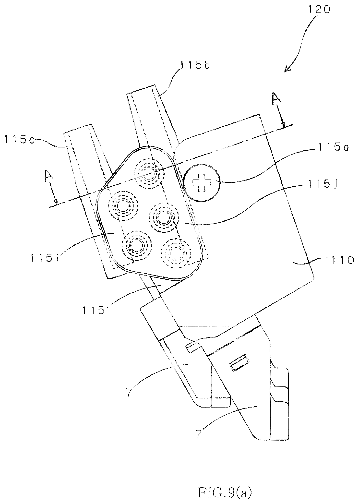
D00016

D00017

D00018

D00019

D00020

D00021

D00022

XML
uspto.report is an independent third-party trademark research tool that is not affiliated, endorsed, or sponsored by the United States Patent and Trademark Office (USPTO) or any other governmental organization. The information provided by uspto.report is based on publicly available data at the time of writing and is intended for informational purposes only.
While we strive to provide accurate and up-to-date information, we do not guarantee the accuracy, completeness, reliability, or suitability of the information displayed on this site. The use of this site is at your own risk. Any reliance you place on such information is therefore strictly at your own risk.
All official trademark data, including owner information, should be verified by visiting the official USPTO website at www.uspto.gov. This site is not intended to replace professional legal advice and should not be used as a substitute for consulting with a legal professional who is knowledgeable about trademark law.