Devices and methods for treatment of vascular aneurysms
Kim , et al. Nov
U.S. patent number 10,470,868 [Application Number 14/990,698] was granted by the patent office on 2019-11-12 for devices and methods for treatment of vascular aneurysms. This patent grant is currently assigned to Thomas J. Fogarty. The grantee listed for this patent is Thomas J. Fogarty. Invention is credited to Steven W. Kim, Brian K. Shiu.


View All Diagrams
| United States Patent | 10,470,868 |
| Kim , et al. | November 12, 2019 |
Devices and methods for treatment of vascular aneurysms
Abstract
The present invention relates to devices and methods for the treatment of diseases in the vasculature, and more specifically, devices and methods for treatment of aneurysms found in blood vessels. In a first embodiment of the present invention, a two part prostheses, where one part is an expandable sponge structure and the other part is an expandable tubular mesh structure, is provided. In the first embodiment, the expandable sponge structure is intended to fill the aneurysm cavity to prevent further dilatation of the vessel wall by creating a buffer or barrier between the pressurized pulsating blood flow and the thinning vessel wall. In the first embodiment, the expandable tubular mesh structure is placed across the aneurysm, contacting the inner wall of healthy vessel proximal and distal to the aneurysm.
| Inventors: | Kim; Steven W. (Los Altos, CA), Shiu; Brian K. (Sunnyvale, CA) | ||||||||||
|---|---|---|---|---|---|---|---|---|---|---|---|
| Applicant: |
|
||||||||||
| Assignee: | Fogarty; Thomas J. (Mountain
View, CA) |
||||||||||
| Family ID: | 32324461 | ||||||||||
| Appl. No.: | 14/990,698 | ||||||||||
| Filed: | January 7, 2016 |
Prior Publication Data
| Document Identifier | Publication Date | |
|---|---|---|
| US 20160113659 A1 | Apr 28, 2016 | |
Related U.S. Patent Documents
| Application Number | Filing Date | Patent Number | Issue Date | ||
|---|---|---|---|---|---|
| 14225730 | Mar 26, 2014 | 9561096 | |||
| 14087980 | Jan 20, 2015 | 8936633 | |||
| 13663272 | Feb 11, 2014 | 8647377 | |||
| 13533658 | Sep 17, 2013 | 8535367 | |||
| 11552913 | Jul 31, 2012 | 8231665 | |||
| 10301061 | Nov 20, 2002 | ||||
| 60333373 | Nov 26, 2001 | ||||
| Current U.S. Class: | 1/1 |
| Current CPC Class: | A61B 17/12118 (20130101); A61B 17/12195 (20130101); A61B 17/1219 (20130101); A61B 17/12036 (20130101); A61F 2/954 (20130101); A61B 17/12136 (20130101); A61F 2/958 (20130101); A61F 2/90 (20130101); A61F 2/07 (20130101); A61B 17/12186 (20130101); A61B 17/12022 (20130101); A61F 2250/0003 (20130101); A61B 2017/00898 (20130101); A61B 2017/00986 (20130101); A61F 2002/065 (20130101); A61F 2002/077 (20130101); A61B 2017/3484 (20130101); A61B 2017/1205 (20130101); A61F 2002/823 (20130101) |
| Current International Class: | A61F 2/06 (20130101); A61F 2/07 (20130101); A61B 17/12 (20060101); A61F 2/958 (20130101); A61F 2/90 (20130101); A61F 2/954 (20130101); A61B 17/00 (20060101); A61B 17/34 (20060101); A61F 2/82 (20130101) |
References Cited [Referenced By]
U.S. Patent Documents
| 2903365 | September 1959 | O'Brian et al. |
| 4085757 | April 1978 | Pevsner |
| 4108173 | August 1978 | Silvenko |
| 4301803 | November 1981 | Handa et al. |
| 4341218 | July 1982 | U |
| 4346712 | August 1982 | Handa et al. |
| 4553545 | November 1985 | Maass et al. |
| 4577631 | March 1986 | Kreamer |
| 4638803 | January 1987 | Rand |
| 4641653 | February 1987 | Rockey |
| 4728328 | March 1988 | Hughes et al. |
| 4944745 | July 1990 | Sogard et al. |
| 4994069 | February 1991 | Ritchart et al. |
| 5078726 | January 1992 | Kreamer |
| 5104404 | April 1992 | Wolff |
| 5133731 | July 1992 | Butler et al. |
| 5151105 | September 1992 | Kwan-Gett |
| 5156620 | October 1992 | Pigott |
| 5163953 | November 1992 | Vince |
| 5192301 | March 1993 | Kamiya et al. |
| 5226911 | July 1993 | Chee et al. |
| 5282824 | February 1994 | Gianturco |
| 5308356 | May 1994 | Blackshear, Jr. et al. |
| 5312415 | May 1994 | Palermo |
| 5330528 | July 1994 | Lazim |
| 5334217 | August 1994 | Das |
| 5360443 | November 1994 | Barone et al. |
| 5395333 | March 1995 | Brill |
| 5411550 | May 1995 | Herweck et al. |
| 5478309 | December 1995 | Sweezer et al. |
| 5530528 | June 1996 | Houki et al. |
| 5534024 | July 1996 | Rogers et al. |
| 5540711 | July 1996 | Kieturakis et al. |
| 5558642 | September 1996 | Schweich, Jr. et al. |
| 5575817 | November 1996 | Martin |
| 5578071 | November 1996 | Parodi |
| 5582619 | December 1996 | Ken |
| 5591195 | January 1997 | Taheri et al. |
| 5593442 | January 1997 | Klein |
| 5613981 | March 1997 | Boyle et al. |
| 5628783 | May 1997 | Quiachon et al. |
| 5665117 | September 1997 | Rhodes |
| 5667767 | September 1997 | Greff et al. |
| 5693088 | December 1997 | Lazarus |
| 5702361 | December 1997 | Evans et al. |
| 5704910 | January 1998 | Humes |
| 5713917 | February 1998 | Leonhardt et al. |
| 5725568 | March 1998 | Hastings |
| 5728131 | March 1998 | Frantzen et al. |
| 5749894 | May 1998 | Engelson |
| 5752974 | May 1998 | Rhee et al. |
| 5766160 | June 1998 | Samson et al. |
| 5769882 | June 1998 | Fogarty et al. |
| 5785679 | July 1998 | Abolfathi et al. |
| 5795331 | August 1998 | Cragg et al. |
| 5800526 | September 1998 | Anderson et al. |
| 5823198 | October 1998 | Jones et al. |
| 5824037 | October 1998 | Fogarty et al. |
| 5824040 | October 1998 | Cox et al. |
| 5830230 | November 1998 | Berryman et al. |
| 5843160 | December 1998 | Rhodes |
| 5861003 | January 1999 | Latson et al. |
| 5876448 | March 1999 | Thompson et al. |
| 5916235 | June 1999 | Guglielmi |
| 5925059 | July 1999 | Palermo et al. |
| 5928260 | July 1999 | Chin et al. |
| 5935145 | August 1999 | Villar et al. |
| 5944733 | August 1999 | Engelson |
| 5951599 | September 1999 | McCrory |
| 5980514 | November 1999 | Kupiecki et al. |
| 5984963 | November 1999 | Ryan et al. |
| 5994750 | November 1999 | Yagi |
| 6015424 | January 2000 | Rosenbluth et al. |
| 6015431 | January 2000 | Thornton et al. |
| 6024754 | February 2000 | Engelson |
| 6059823 | May 2000 | Holman et al. |
| 6063121 | May 2000 | Xavier et al. |
| 6066149 | May 2000 | Samson et al. |
| 6080194 | June 2000 | Pachence et al. |
| 6093199 | July 2000 | Brown et al. |
| 6096021 | August 2000 | Helm et al. |
| 6102940 | August 2000 | Robichon et al. |
| 6110198 | August 2000 | Fogarty et al. |
| 6113629 | September 2000 | Ken |
| 6136015 | October 2000 | Kurz et al. |
| 6139520 | October 2000 | McCrory et al. |
| 6146373 | November 2000 | Cragg et al. |
| 6149664 | November 2000 | Kurz |
| 6152956 | November 2000 | Pierce |
| 6165193 | December 2000 | Greene, Jr. et al. |
| 6165194 | December 2000 | Denardo |
| 6168592 | January 2001 | Kupiecki et al. |
| 6190402 | February 2001 | Horton et al. |
| 6193745 | February 2001 | Fogarty et al. |
| 6196230 | March 2001 | Hall et al. |
| 6203550 | March 2001 | Olson |
| 6203779 | March 2001 | Ricci et al. |
| 6214036 | April 2001 | Letendre et al. |
| 6231562 | May 2001 | Khosravi et al. |
| 6238403 | May 2001 | Greene, Jr. et al. |
| 6248122 | June 2001 | Klumb et al. |
| 6261305 | July 2001 | Marotta et al. |
| 6273909 | August 2001 | Kugler et al. |
| 6273917 | August 2001 | Inoue |
| 6283991 | September 2001 | Cox et al. |
| 6287315 | September 2001 | Wijeratne et al. |
| 6287335 | September 2001 | Drasler et al. |
| 6290731 | September 2001 | Solovay et al. |
| 6293960 | September 2001 | Ken |
| 6296603 | October 2001 | Turnlund et al. |
| 6296604 | October 2001 | Garibaldi et al. |
| 6299597 | October 2001 | Buscemi et al. |
| 6299619 | October 2001 | Greene, Jr. et al. |
| 6312421 | November 2001 | Boock |
| 6312462 | November 2001 | McDermott et al. |
| 6312463 | November 2001 | Rourke et al. |
| 6315709 | November 2001 | Garibaldi et al. |
| 6319276 | November 2001 | Holman et al. |
| 6325819 | December 2001 | Pavcnik et al. |
| 6331184 | December 2001 | Abrams |
| 6334869 | January 2002 | Leonhardt et al. |
| 6344041 | February 2002 | Kupiecki et al. |
| 6344048 | February 2002 | Chin et al. |
| 6344056 | February 2002 | Dehdashtian |
| 6350270 | February 2002 | Roue |
| 6358556 | March 2002 | Ding et al. |
| 6361556 | March 2002 | Chuter |
| 6364823 | April 2002 | Garibaldi et al. |
| 6375668 | April 2002 | Gifford et al. |
| 6375669 | April 2002 | Rosenbluth et al. |
| 6379329 | April 2002 | Naglreiter et al. |
| 6383174 | May 2002 | Eder |
| 6395019 | May 2002 | Chobotov |
| 6409757 | June 2002 | Trout, III et al. |
| 6458119 | October 2002 | Berenstein et al. |
| 6463317 | October 2002 | Kucharczyk et al. |
| 6485510 | November 2002 | Camrud et al. |
| 6494889 | December 2002 | Fleischman et al. |
| 6506204 | January 2003 | Mazzocchi |
| 6511468 | January 2003 | Cragg et al. |
| 6521244 | February 2003 | Kanesaka |
| 6527739 | March 2003 | Bigus et al. |
| 6544219 | April 2003 | Happ et al. |
| 6544276 | April 2003 | Azizi |
| 6551280 | April 2003 | Knighton et al. |
| 6551303 | April 2003 | Van Tassel et al. |
| 6558367 | May 2003 | Cragg et al. |
| 6565602 | May 2003 | Rolando et al. |
| 6585756 | July 2003 | Strecker |
| 6585760 | July 2003 | Fogarty |
| 6589265 | July 2003 | Palmer et al. |
| 6592614 | July 2003 | Lenker et al. |
| 6613037 | September 2003 | Khosravi et al. |
| 6613074 | September 2003 | Mitelberg et al. |
| 6616684 | September 2003 | Vidlund et al. |
| 6626928 | September 2003 | Raymond et al. |
| 6626938 | September 2003 | Butaric et al. |
| 6629947 | October 2003 | Sahatjian et al. |
| 6645167 | November 2003 | Whalen, II et al. |
| 6656214 | December 2003 | Fogarty et al. |
| 6663607 | December 2003 | Slaikeu et al. |
| 6663667 | December 2003 | Dehdashtian et al. |
| 6692510 | February 2004 | West |
| 6695876 | February 2004 | Marotta et al. |
| 6712826 | March 2004 | Lui |
| 6723108 | April 2004 | Jones et al. |
| 6729356 | May 2004 | Baker et al. |
| 6730119 | May 2004 | Smalling |
| 6764510 | July 2004 | Vidlund et al. |
| 6827735 | December 2004 | Greenberg |
| 6843803 | January 2005 | Ryan et al. |
| 6852097 | February 2005 | Fulton, III |
| 6921410 | July 2005 | Porter |
| 7070609 | July 2006 | West |
| 7070616 | July 2006 | Majercak et al. |
| 7081129 | July 2006 | Chobotov |
| 7101396 | September 2006 | Artof et al. |
| 7128736 | October 2006 | Abrams et al. |
| 7147660 | December 2006 | Chobotov et al. |
| 7147661 | December 2006 | Chobotov et al. |
| 7530988 | May 2009 | Evans et al. |
| 7615071 | November 2009 | Chobotov |
| 7708771 | May 2010 | Chuter et al. |
| 8231665 | July 2012 | Kim et al. |
| 8231666 | July 2012 | Kim et al. |
| 8262686 | September 2012 | Fogarty et al. |
| 8361136 | January 2013 | Chobotov |
| 8535367 | September 2013 | Kim et al. |
| 8562662 | October 2013 | Kim et al. |
| 8647377 | February 2014 | Kim et al. |
| 8801769 | August 2014 | Chobotov |
| 8936633 | January 2015 | Kim et al. |
| 9295569 | March 2016 | Kim et al. |
| 9561037 | February 2017 | Fogarty et al. |
| 9561096 | February 2017 | Kim et al. |
| 9561097 | February 2017 | Kim et al. |
| 9615912 | April 2017 | Fogarty et al. |
| 9629636 | April 2017 | Fogarty et al. |
| 9750504 | September 2017 | Fogarty et al. |
| 9913651 | March 2018 | Fogarty et al. |
| 2001/0020184 | September 2001 | Dehdashtian et al. |
| 2001/0044621 | November 2001 | Klumb et al. |
| 2001/0047202 | November 2001 | Slaikeu et al. |
| 2002/0019665 | February 2002 | Dehdashtian et al. |
| 2002/0026217 | February 2002 | Baker et al. |
| 2002/0045848 | April 2002 | Jaafar et al. |
| 2002/0052643 | May 2002 | Wholey et al. |
| 2002/0058986 | May 2002 | Landau et al. |
| 2002/0065542 | May 2002 | Lax et al. |
| 2002/0077693 | June 2002 | Barclay et al. |
| 2002/0082638 | June 2002 | Porter et al. |
| 2002/0082682 | June 2002 | Barclay et al. |
| 2002/0099441 | July 2002 | Dehdashtian |
| 2002/0107565 | August 2002 | Greenhalgh |
| 2002/0151957 | October 2002 | Kerr |
| 2002/0169497 | November 2002 | Wholey et al. |
| 2002/0183841 | December 2002 | Cohn et al. |
| 2002/0193821 | December 2002 | Trout |
| 2003/0004531 | January 2003 | Jones et al. |
| 2003/0014075 | January 2003 | Rosenbluth et al. |
| 2003/0028209 | February 2003 | Teoh et al. |
| 2003/0051735 | March 2003 | Pavcnik et al. |
| 2003/0074017 | April 2003 | Shah |
| 2003/0130724 | July 2003 | DePalma et al. |
| 2003/0171805 | September 2003 | Berg et al. |
| 2003/0195607 | October 2003 | Trout et al. |
| 2003/0204246 | October 2003 | Chu et al. |
| 2003/0216802 | November 2003 | Chobotov |
| 2003/0220666 | November 2003 | Mirigian et al. |
| 2003/0220667 | November 2003 | van der Burg et al. |
| 2003/0229286 | December 2003 | Lenker |
| 2004/0044358 | March 2004 | Khosravi et al. |
| 2004/0044361 | March 2004 | Frazier et al. |
| 2004/0073190 | April 2004 | Deem et al. |
| 2004/0073288 | April 2004 | Kerr |
| 2004/0098027 | May 2004 | Teoh et al. |
| 2004/0116997 | June 2004 | Taylor et al. |
| 2004/0186556 | September 2004 | Hogendijk et al. |
| 2004/0210249 | October 2004 | Fogarty et al. |
| 2004/0254625 | December 2004 | Stephens et al. |
| 2005/0249776 | November 2005 | Chen et al. |
| 2006/0292206 | December 2006 | Kim et al. |
| 2007/0050008 | March 2007 | Kim et al. |
| 2007/0055355 | March 2007 | Kim et al. |
| 2007/0061005 | March 2007 | Kim et al. |
| 2008/0275536 | November 2008 | Zarins et al. |
| 2012/0179192 | July 2012 | Fogarty et al. |
| 2012/0265287 | October 2012 | Sharma et al. |
| 2012/0330343 | December 2012 | Kim et al. |
| 2013/0060320 | March 2013 | Fogarty et al. |
| 2014/0081374 | March 2014 | Kim et al. |
| 2014/0088690 | March 2014 | Fogarty et al. |
| 2014/0142685 | May 2014 | Kim et al. |
| 2017/0020653 | January 2017 | Kim et al. |
| 2017/0020654 | January 2017 | Fogarty et al. |
| 2017/0086853 | March 2017 | Fogarty et al. |
| 2017/0333047 | November 2017 | Fogarty et al. |
| 2017/0360553 | December 2017 | Fogarty et al. |
| 2018/0199946 | July 2018 | Fogarty et al. |
| 2003/204493 | Dec 2003 | AU | |||
| 2689388 | Jul 1999 | FR | |||
| WO 1999/016384 | Apr 1999 | WO | |||
| WO 1999/043273 | Sep 1999 | WO | |||
| WO 1999/065418 | Dec 1999 | WO | |||
| WO 2000/069367 | Nov 2000 | WO | |||
| WO 2001/006950 | Feb 2001 | WO | |||
| WO 2001/028434 | Apr 2001 | WO | |||
| WO 2001/093920 | Dec 2001 | WO | |||
| WO 2002/102282 | Dec 2002 | WO | |||
| WO 2004/045393 | Jun 2004 | WO | |||
Other References
|
Franklin et al, "Uptake of Tetracycline by Aortic Aneurysm Wall and Its Effect on Inflammation and Proteolysis," Brit. J. Surgery, 86(6):771-775, 1999. cited by applicant . Pyo et al., "Targeted Gene Disruption of Matrix Metalloproteinase-9 (Gelatinase B) Suppresses Development of Experimental Abdominal Aortic Aneurysms," J. Clinical Investigation, 105(11):1641-1649, 2000. cited by applicant . Tambiah et al, "Provocation of Experimental Aortic Inflammation Mediators and Chlamydia Pneumoniae," Brit. J. Surgery, 88(7):935-940, 2001. cited by applicant . Villareal et al, "Early Results Using Bare Metal Stents With or Without Coil Embolization for AAA Exclusion," Journal of endovascular therapy : an official journal of the International Society of Endovascular Specialists, 8 pages, 2001. cited by applicant . Walton, et al, "Inhibition of Prostoglandin E2 Synthesis in Abdominal Aortic Aneurysms," Circulation, pp. 48-54, Jul. 6, 1999. cited by applicant . Xu et al, "Sp 1 Increases Expression of Cyclooxygenase-2 in Hypoxic Vascular Endothelium," J. Biological Chemistry, 275(32):24583-24589, 2000. cited by applicant . U.S. Appl. No. 10/301,061, filed Nov. 20, 2002. cited by applicant . U.S. Appl. No. 11/555,938, filed Nov. 2, 2006. cited by applicant . U.S. Appl. No. 11/552,913, filed Oct. 25, 2006. cited by applicant . U.S. Appl. No. 11/552,925, filed Oct. 25, 2006. cited by applicant . U.S. Appl. No. 13/533,658, filed Jun. 26, 2012. cited by applicant . U.S. Appl. No. 13/663,272, filed Oct. 29, 2012. cited by applicant . U.S. Appl. No. 14/087,980, filed Nov. 22, 2013. cited by applicant . U.S. Appl. No. 14/165,140, filed Jan. 27, 2014. cited by applicant . U.S. Appl. No. 14/225,730, filed Mar. 26, 2014. cited by applicant. |
Primary Examiner: Severson; Ryan J.
Attorney, Agent or Firm: Levine Bagade Han LLP
Parent Case Text
CROSS-REFERENCE TO RELATED APPLICATION
This application is a continuation of U.S. patent application Ser. No. 14/225,730, filed Mar. 26, 2014, which is a continuation of U.S. patent application Ser. No. 14/087,980, filed Nov. 22, 2013, (now U.S. Pat. No. 8,936,633 issued Jan. 20, 2015), which is a continuation and claims the benefit of U.S. patent application Ser. No. 13/663,272, filed Oct. 29, 2012, (now U.S. Pat. No. 8,647,377 issued Feb. 11, 2014), which is a continuation of U.S. patent application Ser. No. 13/533,658, filed Jun. 26, 2012, (now U.S. Pat. No. 8,535,367 issued Sep. 17, 2013) which is a continuation of U.S. patent application Ser. No. 11/552,913, filed Oct. 25, 2006, (now U.S. Pat. No. 8,231,665 issued Jul. 31, 2012), which is a continuation of U.S. patent application Ser. No. 10/301,061, filed Nov. 20, 2002, now abandoned, which claims the benefit of U.S. Provisional Application No. 60/333,373, filed Nov. 26, 2001, which are all incorporated herein by reference in their entireties.
Claims
We claim:
1. A system for treating an aneurysm comprising: a catheter delivery system having a distal tip, wherein when the catheter delivery system is in a deployed configuration, the distal tip of the catheter delivery system is placed between an outside surface of a stent and a luminal wall of the aneurysm; and an aneurysm filler, wherein the aneurysm filler is passable through the distal tip of the catheter delivery system such that the aneurysm filler, when in a first deployed configuration, deploys through the distal tip between the outside surface of the stent and the luminal wall, wherein when the aneurysm filler is in a second deployed configuration, a portion of the aneurysm filler contacts the stent and the luminal wall, wherein the aneurysm filler forms into a foam configuration when exposed to a fluid, wherein when the aneurysm filler is in the first deployed configuration, the aneurysm filler has a first length, wherein when the aneurysm filler is in the second deployed configuration, the aneurysm filler has a second length, wherein the second length is greater than the first length, and wherein the second length has more bends than the first length.
2. The system of claim 1, wherein the stent bifurcates at a bifurcation point, wherein when the catheter delivery system is in the deployed configuration, the distal tip of the catheter delivery system is superior to the bifurcation point, wherein the aneurysm filler is deployable through the catheter delivery system such that the aneurysm filler exits the catheter delivery system in a direction parallel to a length of a longitudinal axis of the catheter delivery system, wherein the aneurysm filler expands into an expanded configuration when exposed to the fluid, and wherein the fluid is blood.
3. The system of claim 1, wherein the stent bifurcates at a bifurcation point.
4. The system of claim 3, wherein the distal tip of the catheter delivery system is superior to the bifurcation point when the catheter delivery system is in the deployed configuration.
5. The system of claim 1, wherein the aneurysm filler is deployable through the catheter delivery system such that the aneurysm filler exits the catheter delivery system in a direction parallel to a length of a longitudinal axis of the catheter delivery system.
6. The system of claim 1, wherein the aneurysm filler expands into an expanded configuration when exposed to the fluid.
7. The system of claim 1, wherein the fluid is blood.
8. The system of claim 1, wherein the aneurysm filler is porous.
9. The system of claim 1, wherein when the aneurysm filler is in the second deployed configuration, the aneurysm filler coils in the aneurysm.
10. The system of claim 1, wherein the aneurysm filler is expandable to a size greater than an open cell of the stent.
11. The system of claim 1, wherein the aneurysm filler is a polymer.
12. The system of claim 1, wherein when the aneurysm filler is in the second deployed configuration, the aneurysm filler has a fold.
13. A system for treating an aneurysm comprising: a catheter having a distal end, wherein when the catheter is in a deployed configuration, the distal end of the catheter is placed within the aneurysm between an outer surface of a stent and a luminal wall of the aneurysm; an aneurysm filler; and an outer skin, wherein the aneurysm filler is passable through s the distal end of the catheter in a direction parallel to a length of a longitudinal axis of the catheter, wherein when the aneurysm filler is in a deployed configuration, a portion of the aneurysm filler is between the stent and the outer skin, wherein the aneurysm filler forms into an expanded foam configuration when exposed to blood, wherein when the aneurysm filler expands into the expanded foam configuration, the aneurysm filler is larger than an open cell of the stent, wherein the stent is configured to bifurcate at a bifurcation point, wherein the distal end of the catheter is superior to the bifurcation point when the catheter is in the deployed configuration, wherein when the aneurysm filler is in the deployed configuration, the aneurysm filler is a continuous foam structure, and wherein when the aneurysm filler is in the deployed configuration, the continuous foam structure is foldable between the outside surface of the stent and the luminal wall of the aneurysm.
14. The system of claim 13, wherein the aneurysm filler is a polymer.
15. The system of claim 13, wherein when the aneurysm filler is in the expanded foam configuration, the aneurysm filler is porous.
16. The system of claim 13, wherein, when the aneurysm filler is in the deployed configuration, the aneurysm filler coils between the outer surface of the stent and the luminal wall.
17. A method for treating an aneurysm comprising: placing a distal end of a catheter delivery system within the aneurysm between an outer surface of a stent and a luminal wall of the aneurysm; and introducing an aneurysm filler and an outer skin, wherein the aneurysm filler is passable through the distal end of the catheter delivery system such that the aneurysm filler exits the distal end between the outer surface of the stent and the luminal wall, wherein the aneurysm filler has a first deployed configuration and a second deployed configuration, wherein when the aneurysm filler is in the second deployed configuration, a first side of the outer skin contacts the aneurysm filler and a second side of the outer skin contacts the luminal wall, wherein the aneurysm filler forms into an expanded foam configuration when exposed to a fluid, wherein when the aneurysm filler is in the first deployed configuration, the aneurysm filler has a first length, wherein when the aneurysm filler is in the second deployed configuration, the aneurysm filler has a second length, and wherein the second length has more bends than the first length.
18. The method of claim 17, wherein the aneurysm filler is a polymer, wherein the aneurysm filler exits the distal end of the catheter delivery system in a direction parallel to a length of a longitudinal axis of the catheter delivery system, wherein the aneurysm filling in the expanded foam configuration is larger than an open cell of the stent, wherein the fluid is blood, wherein the stent bifurcates at a bifurcation point, and wherein the distal end of the catheter delivery system is superior to the bifurcation point when the catheter delivery system is in a deployed configuration.
19. The method of claim 17, wherein when the aneurysm filler is in the second deployed configuration, the outer skin is in conformal contact with a wall of the aneurysm.
20. The method of claim 17, wherein, when the aneurysm filler is in the second deployed configuration, the aneurysm filler is fully confined within the aneurysm.
21. The method of claim 17, wherein the aneurysm filler coils in the aneurysm.
Description
BACKGROUND OF THE INVENTION
The present invention relates to devices and methods for the treatment of diseases in the vasculature, and more specifically, devices and methods for treatment of aneurysms found in blood vessels. Aneurysms can occur in various areas of the cardiovascular system, but are commonly found in the abdominal aorta, thoracic aorta, and cerebral vessels. Aneurysms are unusual ballooning of the vessel due to loss of strength and/or elasticity of the vessel wall. With the constant pulsating pressure exerted on the vessel wall, the diseased or weakened wall can expand out and potentially rupture, which frequently leads to fatality. Prior methods of treating aneurysms have consisted of invasive surgical techniques. The technique involves a major cut down to access the vessel, and the diseased portion of the vessel is replaced by a synthetic tubular graft. Accordingly, this invasive surgical procedure has high mortality and morbidity rates.
Due to the inherent risks and complexities of the surgical procedures, various attempts have been made to develop minimally invasive methods to treat these aneurysms. For treatment of abdominal and thoracic aortic aneurysms, most of the attempts are catheter-based delivery of an endoluminal synthetic graft with some metallic structural member integrated into the graft, commonly called stent-grafts. One of the primary deficiencies of these systems is durability of these implants. Because catheter-based delivery creates limitations on size and structure of the implant that you can deliver to the target site, very thin synthetic grafts are in attached to metallic structures, where constant interaction between the two with every heartbeat can cause wear on the graft. Also, the metallic structures often see significant cyclical loads from the pulsating blood, which can lead to fatigue failure of the metallic structure. The combination of a thin fragile graft with a metallic structure without infinite life capabilities can lead to implant failure and can ultimately lead to a fatality.
While the above methods have shown some promise with regard to treating aortic aneurysms with minimally invasive techniques, there remains a need for a treatment system which doesn't rely on the less than optimal combination of a thin graft and metallic structural member to provide long-term positive results. The present invention describes various embodiments and methods to address the shortcomings of current minimally invasive devices and to meet clinical needs.
SUMMARY OF THE INVENTION
In a first aspect, the present invention provides a two part prostheses where one part is an expandable sponge structure and the other part is an expandable tubular mesh structure. The expandable sponge structure is intended to fill the aneurysm cavity to prevent further dilatation of the vessel wall by creating a buffer or barrier between the pressurized pulsating blood flow and the thinning vessel wall. The expandable tubular mesh structure, which is placed across the aneurysm contacting the inner wall of healthy vessel proximal and distal the aneurysm, serves two purposes. One, it defines the newly formed vessel lumen, even though it does not by itself provide a fluid barrier between the blood flow and the aneurysm. Two, it keeps the expandable sponge structure from protruding out of the aneurysm and into the newly formed vessel lumen. The expandable tubular mesh structure is delivered first across the aneurysm. Then, the expandable sponge structure is delivered via a catheter-based delivery system through a "cell" of the tubular mesh structure and into the aneurysm sac. When the sponge structure is deployed into the aneurysm sac and comes in contact with fluid, it will expand to a size larger than the largest opening or cell of the tubular mesh structure as to prevent the sponge structure from getting out of the aneurysm sac. The filled aneurysm sac will most likely clot off and prevent further dilation of the aneurysm and subsequent rupture. The blood flow should maintain a natural lumen where the luminal diameter is approximately defined by the diameter of the tubular mesh structure. The advantage of this system is that the sponge filler material acts like a graft but has unparalleled durability. The metallic structure can be optimized for durability as well because the size constraint is somewhat relieved due to the absence of an integrated graft material, which takes up a significant amount of space in a catheter.
In addition, the expandable sponge structure can be used to repair existing endoluminal stent-grafts which have developed leaks. There are thousands of endoluminal stent-grafts implanted into humans to treat abdominal aortic aneurysms. That number is growing daily. The endoluminal stent-grafts are intended to exclude the aneurysm from blood flow and blood pressure by placing a minimally porous graft supported fully or partially by metallic structural members, typically called stents. The acute success rate of these devices is very high, but there are a significant number of these which develop leaks, or blood flow/pressure re-entering the aneurysm sac, some time after the procedure. If the source of the leak can be accessed by the delivery system, the expandable sponge structure can be deployed through that access point.
In another aspect, the present invention provides an inflatable tubular balloon graft. It is a tubular graft, straight or bifurcated, where its wall is not a solid structure but a hollow chamber. The chamber can be filled with a variety of materials which can dictate the mechanical properties of the prostheses. The unfilled tubular balloon graft can be folded and loaded into a catheter-based delivery system, and once in position the tubular balloon graft can be "inflated" with the filler material. The material would be filled in a fluid form and may stay a fluid form or can be solidified by various means such as UV light, heat, and time. The advantage of this system is that a metallic structure is not needed to provide structure to the graft. It is instead replaced by the injectable fluid within the chamber of the tubular balloon graft. Customization of the mechanical properties of the graft is easily accomplished by using balloon fillers of varying properties.
The tubular balloon graft can be completely non-porous, completely porous with same degree of porosity throughout the graft, completely porous with varying porosity within the graft, or partially non-porous and partially porous. Significant porosity on the very outer layer would allow for delivery of an aneurysm sac filling substance or a drug. Porosity on the ends of the graft will help promote cellular in-growth. Porosity on the ends can also be used to deliver an adhesive so that the graft can be securely attached to the vessel wall.
Another embodiment of the tubular balloon graft includes a tubular balloon graft with a bulging outer layer. This will allow the outer surface of the tubular balloon graft to fill some or all of the aneurysm. This will provide a primary or secondary barrier for the aneurysm wall from the pulsating blood flow and will provide a means to prevent migration of the graft due to the enlarged area within the graft. An alternate method of construction would be to attach a bulging outer skin to a standard tubular thin-walled graft and provide a port for injection of the filler substance. Alternatively, instead of a bulging outer skin, a very compliant outer skin can be used so that the volume of material is minimized. The compliant outer skin would be able to expand at very low inflation pressures that would be non-destructive to the aneurysm wall.
BRIEF DESCRIPTION OF THE DRAWINGS
FIG. 1A illustrates the two-part prosthesis.
FIG. 1B illustrates a bifurcated version of the expandable tubular mesh structure and the expandable sponge structure.
FIG. 1C illustrates an expandable tubular mesh structure placed across an aneurysm and the expandable sponge structure filling up the aneurysm.
FIGS. 2A-2C illustrate the various cross-sections of the expandable sponge structure.
FIG. 3A illustrates a long continuous sponge structure.
FIG. 3B illustrates multiple short sponge structures.
FIG. 4 illustrates the catheter-based delivery system.
FIG. 5 illustrates a curved delivery catheter.
FIG. 6 illustrates a method of ensuring that the delivery catheter's tip stays inside the aneurysm sac.
FIG. 7A illustrates an expandable basket-like structure.
FIG. 7B illustrates an expandable braid-like structure.
FIGS. 8 and 9 illustrate expandable tubular mesh structures.
FIG. 10 illustrates a delivery catheter tracked over a guidewire and placed in a stent-graft which developed a leak.
FIG. 11 illustrates the sponge delivered through the delivery catheter.
FIGS. 12-15 illustrate tubular balloon grafts.
FIGS. 16 and 17 illustrate tubular balloon grafts being expanded.
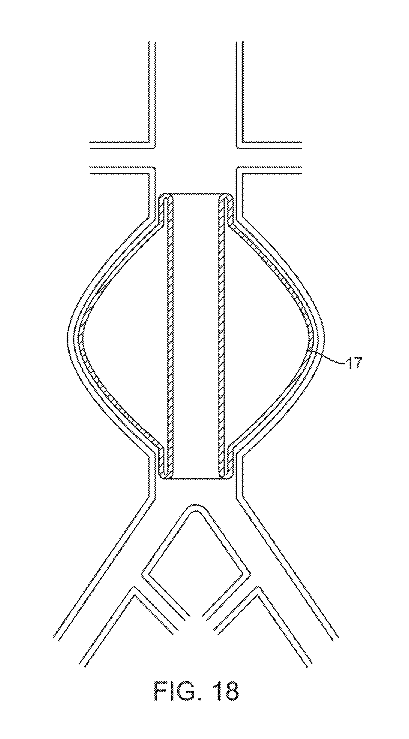
FIG. 18 illustrates a tubular balloon graft.
FIGS. 19, 20A and 20 B illustrate a vascular graft with an integrated tubular balloon.
FIGS. 21A-21E illustrate a method of delivering a graft with an external balloon.
DETAILED DESCRIPTION OF THE INVENTION
FIG. 1A shows the two-part prosthesis comprising of an expandable sponge structure 1 and an expandable tubular mesh structure 2 placed in an abdominal aortic aneurysm 3 located in the infra-renal aorta not involving the iliac arteries. FIG. 1B shows a bifurcated version of the expandable tubular mesh structure 2 and the expandable sponge structure 1 in an abdominal aortic aneurysm located in the infra-renal aorta and involving, both iliac arteries. FIG. 1C shows an expandable tubular mesh structure 2 placed across an aneurysm commonly found in cerebral arteries and the expandable sponge structure 1 filling up the aneurysm. The expandable sponge structure 1 is placed through the expandable tubular mesh structure 2 into the aneurysm, filling up the aneurysmal sac which provides a barrier between the thin fragile wall of the aneurysm and the pressurized pulsating blood. The tubular mesh structure 2 keeps the expanded sponge 1 within the confines of the aneurysm and away from the flow path.
The expandable sponge structure 1 is preferably made of common medical grade polymers or natural substances like collagen which can be manufactured into a sponge structure. The sponge structure can be processed in such a way so that it can be compressed to a dry condition size substantially smaller than the wet condition size, exhibiting huge expansion ratio. The expanded sponge structure can take various forms. FIGS. 2A-2C show the various expanded cross-sections that the expandable sponge structure 1 can be. FIG. 2A shows a circular cross section. FIG. 2B shows a square cross section, and FIG. 2C show a triangular cross section. Any cross section can be used. The most important requirement is that it cannot escape from the aneurysm sac through a cell of the expandable tubular mesh structure 2. The length of the expandable sponge structure 1 can vary as well. FIG. 3A shows a long continuous structure 1. And FIG. 3B shows multiple short structures 1.
One method of delivering the sponge filler 1 into the aneurysm sac is shown by the catheter-based delivery system in FIG. 4. The catheter 4 can hold the compressed sponge 1 within its lumen, and when pushed out with the plunger 5 into the blood filled aneurysm sac, the sponge will expand out to a substantially larger size. The expanded size of the sponge filler is preferably larger than the largest opening of the tubular mesh structure as to prevent the sponge from escaping the aneurysm sac. FIG. 5 shows an example of a curved delivery catheter 4, where the tip is placed through a cell of the tubular mesh structure 2 and the expandable sponge structure 1 is being deployed into the aneurysm sac. It is important that the tip of the delivery catheter is through a cell of the tubular mesh structure into the aneurysm because the expandable sponge will expand very quickly after being exposed to the blood and being unconstrained by a catheter. FIG. 6 shows a method of ensuring that the delivery catheter's 4 tip stays inside the aneurysm sac by having a balloon 6 on the tip of it, and when inflated after the tip is within the aneurysm sac it will prevent the catheter tip from backing out of the aneurysm sac. FIG. 7A shows an expandable basket-like structure 7 and FIG. 7B shows an expandable braid-like structure 6 which are alternatives to having a balloon 6 on the tip of the catheter 4.
The expandable tubular mesh structure 2 can be made of a metal or of a polymer. The versions made of a metal can be self-expanding from a smaller compressed state or balloon expandable from a smaller compressed or as-cut state. The self-expanding version may be made of metals which exhibit large amounts of elasticity (i.e. nickel-titanium, spring steel, MP-35N and elgiloy) such that when they are compressed down from their expanded state to the compressed state to load into a delivery catheter, they will substantially return to their expanded condition when released from the catheter. Alternatively, shape memory metals like nickel-titanium can be used to provide large expansion ratios. The balloon expandable version may be made of metals which exhibit large permanent deformations without significantly compromising the mechanical performance. The following are some common medical grade metals which are well suited for this purpose: stainless steel, titanium, tantulum, and martensitic nickel titanium. In either the self-expanding or the balloon expandable case, the intent is to deliver the expandable tubular mesh 2 to the target site in a smaller or compressed condition via a catheter-based delivery system so that the target site can be accessed through a remote vascular access point which is conducive to a percutaneous or minimally invasive approach.
The expandable tubular mesh structure 2 shown in FIGS. 1A, 1B, 1C, 5, and 6 represent a generic, mesh structure. FIG. 8 shows an expandable tubular mesh structure where long continuous struts 9 are connected to anchoring end members 10. This allows the structure to be very low in profile in the compressed state, and the durability of this type of structure can be optimized because no radial element exists in the longitudinal struts 9. FIG. 9 show an alternate expandable tubular mesh structure preferably made from a polymer such as PTFE, Polyester, Polyurethane, and the like. The structure has relatively large holes 11 to give access to the expandable sponge delivery catheter. The ends incorporate an anchoring member 12, either self-expanding or balloon expandable.
FIG. 10 shows a delivery catheter 4 which has been tracked over a guidewire 14, which has been placed into the aneurysm sac through an opening 15 of an existing endoluminal stent-graft 13 which developed a leak. The balloon 6 on the delivery catheter 4 was inflated after the delivery catheter 4 was positioned within the aneurysm sac. FIG. 11 shows the guidewire 14 removed, and the expandable sponge structure 1 being delivered through the delivery catheter 4.
FIG. 12 shows a section view of a tubular balloon graft 19 positioned across an infra-renal aortic aneurysm blocking off the flow to the aneurysm sac. The tubular balloon graft's 19 wall is made of an inner wall 16, an outer wall 17 and a chamber 18 between them. The chamber 18 can be filled with various materials to dictate the mechanical properties of the prosthesis. FIG. 13 shows a bifurcated tubular balloon graft 20 positioned across an infra-renal aortic aneurysm with bi-lateral iliac involvement.
The tubular balloon implant can be made of the various biocompatible materials used to make balloon catheters. Those materials include P.E.T. (Polyester), nylon, urethane, and silicone. It can also be made of other implant grade materials such as ePTFE. One method of making such a device is to start with two thin walled tubes of differing diameters. The difference between the diameters of the tubes will dictate the volume of the balloon chamber. The ends of the tubes can be sealed together with adhesive or by heat to form the balloon chamber. A communication port will be necessary to be able to fill the port with the injected material.
The injected material can be an epoxy, a UV-curable epoxy, silicone, urethane or other type of biocompatible materials such as albumin, collagen, and gelatin glue which is injected into the balloon, and then cured in situ. Or, the injected material doesn't necessarily have to be cured. The as-delivered state may provide the appropriate mechanical properties for the application. Therefore, substances like sterile saline, biocompatible oils, or biocompatible adhesives can be left in the tubular balloon in the as-delivered state.
The tubular balloon graft can be non-porous to very porous. FIG. 14 shows a version where the tubular balloon graft has a porous outer wall 24. The chamber 21 of the tubular balloon graft can be used to deliver an aneurysm sac filling substance such as UV curable adhesive 22. The holes 23 which dictate the porosity of the tubular balloon graft can be created with laser drilling, etching, and other methods. The porosity can be varied in select areas of the graft. FIG. 15 shows a tubular balloon graft with only the ends of the graft have porosity to either promote cellular in-growth or to inject an adhesive which allows secure attachment of the graft ends to the vessel wall.
FIG. 16 shows a tubular balloon graft 19 which is being expanded from a folded condition (not shown) by a balloon catheter 25. Once expanded, the chamber 18 of the tubular balloon graft 19 can be filled with the desired substance through the chamber access port 26. FIG. 17 shows a tubular balloon graft 19 being expanded by an inflation process or filling the chamber 18 of the tubular balloon graft 19 through the chamber access port 26.
FIG. 18 shows a version of the tubular balloon graft with an outer wall 17 which is substantially bulged out so that it fills some or all of the aneurysm sac. FIG. 19 shows a vascular graft 27 which has an integrated balloon 28 attached to the outside surface of the graft. The balloon can be pre-bulged and folded down for delivery, or it can be a very compliant material like silicone, urethane, or latex so that it has no folds whether compressed or expanded. FIG. 20A shows the same type of implant, a graft 27 with an external balloon 28, used in a cerebral vessel aneurysm 29. FIG. 20B show the same implant as 20A, except that the implant balloon does not fully till the aneurysm, which can be acceptable because the graft 27 excludes the aneurysm from the blood flow, and the primary purpose of the balloon 28 is to prevent migration of the graft 27.
The graft 27 can be made of commonly used implant polymers such as PTFE, Polyester, Polyurethane, etc. The balloon 28 surrounding the graft can be made of the same commonly used vascular implant materials as well. The graft and balloon materials can be different, but it is commonly known that using the same material for both would facilitate processing/manufacturing. The theory is that the balloon 28 would preferentially only deploy into the aneurysm sac were the resistance to expansion is minimal as compared to the vessel wall. The graft 27 would provide the primary barrier between the pressurized blood and the thin wall of the aneurysm. Secondarily, the balloon itself provides a buffer from the pressurized blood. The balloon's 28 primary function, however, is to hold the graft 27 in place. Since the expanded section of the implant is "locked" into the aneurysm, the graft 27 should not migrate. Also, the balloon 28, in the filled state, will provide hoop strength to the graft 27.
FIGS. 21A-21E demonstrate one method of delivering a graft with an external balloon to the target site. FIG. 21A shows the implant loaded onto a balloon delivery catheter 30 with an outer sheath 32 and positioned over a guide wire 31 at the aneurysm target site. FIG. 21B shows that once in position, the outer sheath 32 is withdrawn. FIG. 21C shows the balloon delivery catheter 33 being inflated, pushing the implant 34 against the healthy vessel walls on both sides of the aneurysm. FIG. 21D shows that the balloon delivery catheter 30 may also have an implant balloon inflation port 35 which can now be used to fill up the implant balloon 28 with a biocompatible substance. The substance can be sterile saline, contrast agent, hydrogel, and UV cure adhesive to name a few. Most likely, low inflation pressures would be used to fill the implant balloon 28. FIG. 21E shows that once the implant balloon 28 is filled, the implant balloon inflation port 35 can be detached and the delivery catheter 30 removed.
* * * * *
D00000
D00001
D00002
D00003
D00004
D00005
D00006
D00007
D00008
D00009
D00010
D00011
D00012

D00013

D00014

D00015

D00016

D00017

D00018

D00019
D00020

D00021

D00022

D00023

D00024

D00025

D00026

XML
uspto.report is an independent third-party trademark research tool that is not affiliated, endorsed, or sponsored by the United States Patent and Trademark Office (USPTO) or any other governmental organization. The information provided by uspto.report is based on publicly available data at the time of writing and is intended for informational purposes only.
While we strive to provide accurate and up-to-date information, we do not guarantee the accuracy, completeness, reliability, or suitability of the information displayed on this site. The use of this site is at your own risk. Any reliance you place on such information is therefore strictly at your own risk.
All official trademark data, including owner information, should be verified by visiting the official USPTO website at www.uspto.gov. This site is not intended to replace professional legal advice and should not be used as a substitute for consulting with a legal professional who is knowledgeable about trademark law.