Tool detection and alignment for tool installation
Hebebrand , et al. No
U.S. patent number 10,465,457 [Application Number 15/233,333] was granted by the patent office on 2019-11-05 for tool detection and alignment for tool installation. This patent grant is currently assigned to WEATHERFORD TECHNOLOGY HOLDINGS, LLC. The grantee listed for this patent is Weatherford Technology Holdings, LLC. Invention is credited to Christina Karin Hebebrand, Martin Liess, John Fielding Ownby, Bjoern Thiemann, Frank Wern, Aicam Zouhair.


View All Diagrams
| United States Patent | 10,465,457 |
| Hebebrand , et al. | November 5, 2019 |
Tool detection and alignment for tool installation
Abstract
A modular top drive system for construction of a wellbore includes an alignment assembly configured to align a tool with a top drive unit to facilitate automatic tool installation during rig up.
| Inventors: | Hebebrand; Christina Karin (Hannover, DE), Thiemann; Bjoern (Burgwedel, DE), Liess; Martin (Seelze, DE), Wern; Frank (Hannover, DE), Zouhair; Aicam (Houston, TX), Ownby; John Fielding (Houston, TX) | ||||||||||
|---|---|---|---|---|---|---|---|---|---|---|---|
| Applicant: |
|
||||||||||
| Assignee: | WEATHERFORD TECHNOLOGY HOLDINGS,
LLC (Houston, TX) |
||||||||||
| Family ID: | 56694281 | ||||||||||
| Appl. No.: | 15/233,333 | ||||||||||
| Filed: | August 10, 2016 |
Prior Publication Data
| Document Identifier | Publication Date | |
|---|---|---|
| US 20170044854 A1 | Feb 16, 2017 | |
Related U.S. Patent Documents
| Application Number | Filing Date | Patent Number | Issue Date | ||
|---|---|---|---|---|---|
| 62203692 | Aug 11, 2015 | ||||
| Current U.S. Class: | 1/1 |
| Current CPC Class: | E21B 47/002 (20200501); E21B 19/00 (20130101); G06T 7/0004 (20130101); E21B 19/165 (20130101); E21B 44/00 (20130101); E21B 3/02 (20130101); G06T 2207/10012 (20130101) |
| Current International Class: | E21B 19/16 (20060101); E21B 3/02 (20060101); E21B 44/00 (20060101); E21B 47/00 (20120101); G06T 7/00 (20170101); E21B 19/00 (20060101) |
References Cited [Referenced By]
U.S. Patent Documents
| 1367156 | February 1921 | McAlvay et al. |
| 1822444 | September 1931 | MacClatchie |
| 2370354 | February 1945 | Hurst |
| 2683379 | July 1954 | Strandgren |
| 3147992 | September 1964 | Haeber et al. |
| 3354951 | November 1967 | Savage et al. |
| 3385370 | May 1968 | Knox et al. |
| 3662842 | May 1972 | Bromell |
| 3698426 | October 1972 | Litchfield et al. |
| 3747675 | July 1973 | Brown |
| 3766991 | October 1973 | Brown |
| 3774697 | November 1973 | Brown |
| 3776320 | December 1973 | Brown |
| 3842619 | October 1974 | Bychurch, Sr. |
| 3888318 | June 1975 | Brown |
| 3899024 | August 1975 | Tonnelli et al. |
| 3913687 | October 1975 | Gyongyosi et al. |
| 3915244 | October 1975 | Brown |
| 3917092 | November 1975 | McGinnis |
| 3964552 | June 1976 | Slator |
| 4022284 | May 1977 | Crow |
| 4051587 | October 1977 | Boyadjieff |
| 4100968 | July 1978 | Delano |
| 4192155 | March 1980 | Gray |
| 4199847 | April 1980 | Owens |
| 4235469 | November 1980 | Denny et al. |
| 4364407 | December 1982 | Hilliard |
| 4377179 | March 1983 | Giebeler |
| 4402239 | September 1983 | Mooney |
| 4449596 | May 1984 | Boyadjieff |
| 4478244 | October 1984 | Garrett |
| 4497224 | February 1985 | Jurgens |
| 4593773 | June 1986 | Skeie |
| 4647050 | March 1987 | Johnson |
| 4762187 | August 1988 | Haney |
| 4776617 | October 1988 | Sato |
| 4779688 | October 1988 | Baugh |
| 4791997 | December 1988 | Krasnov |
| 4813493 | March 1989 | Shaw et al. |
| 4815546 | March 1989 | Haney et al. |
| 4821814 | April 1989 | Willis et al. |
| 4844181 | July 1989 | Bassinger |
| 4867236 | September 1989 | Haney et al. |
| 4916959 | April 1990 | Lively |
| 4932253 | June 1990 | McCoy |
| 4955949 | September 1990 | Bailey et al. |
| 4962819 | October 1990 | Bailey et al. |
| 4972741 | November 1990 | Sibille |
| 4981180 | January 1991 | Price |
| 4997042 | March 1991 | Jordan et al. |
| 5018350 | May 1991 | Bender |
| 5020640 | June 1991 | Nederbragt |
| 5036927 | August 1991 | Willis |
| 5099725 | March 1992 | Bouligny, Jr. et al. |
| 5152554 | October 1992 | LaFleur et al. |
| 5172940 | December 1992 | Usui et al. |
| 5191939 | March 1993 | Stokley |
| 5196770 | March 1993 | Champs et al. |
| 5215153 | June 1993 | Younes |
| 5245877 | September 1993 | Ruark |
| 5282653 | February 1994 | LaFleur et al. |
| 5297833 | March 1994 | Willis et al. |
| 5348351 | September 1994 | LaFleur et al. |
| 5385514 | January 1995 | Dawe |
| 5404767 | April 1995 | Sutherland |
| 5433279 | July 1995 | Tessari et al. |
| 5440183 | August 1995 | Denne |
| 5441310 | August 1995 | Barrett et al. |
| 5456320 | October 1995 | Baker |
| 5479988 | January 1996 | Appleton |
| 5486223 | January 1996 | Carden |
| 5501280 | March 1996 | Brisco |
| 5509442 | April 1996 | Claycomb |
| 5540095 | July 1996 | Sherman et al. |
| 5577566 | November 1996 | Albright et al. |
| 5584343 | December 1996 | Coone |
| 5645131 | July 1997 | Trevisani |
| 5664310 | September 1997 | Penisson |
| 5682952 | November 1997 | Stokley |
| 5735348 | April 1998 | Hawkins, III |
| 5778742 | July 1998 | Stuart |
| 5839330 | November 1998 | Stokka |
| 5909768 | June 1999 | Castille et al. |
| 5918673 | July 1999 | Hawkins et al. |
| 5950724 | September 1999 | Giebeler |
| 5971079 | October 1999 | Mullins |
| 5992520 | November 1999 | Schultz et al. |
| 6003412 | December 1999 | Dlask et al. |
| 6011508 | January 2000 | Perreault et al. |
| 6053191 | April 2000 | Hussey |
| 6101952 | August 2000 | Thornton et al. |
| 6102116 | August 2000 | Giovanni |
| 6142545 | November 2000 | Penman et al. |
| 6161617 | December 2000 | Gjedebo |
| 6173777 | January 2001 | Mullins |
| 6276450 | August 2001 | Seneviratne |
| 6279654 | August 2001 | Mosing et al. |
| 6289911 | September 2001 | Majkovic |
| 6309002 | October 2001 | Bouligny |
| 6311792 | November 2001 | Scott et al. |
| 6328343 | December 2001 | Hosie et al. |
| 6378630 | April 2002 | Ritorto et al. |
| 6390190 | May 2002 | Mullins |
| 6401811 | June 2002 | Coone |
| 6415862 | July 2002 | Mullins |
| 6431626 | August 2002 | Bouligny |
| 6443241 | September 2002 | Juhasz et al. |
| 6460620 | October 2002 | LaFleur |
| 6499701 | December 2002 | Thornton et al. |
| 6508132 | January 2003 | Lohr et al. |
| 6527047 | March 2003 | Pietras |
| 6536520 | March 2003 | Snider et al. |
| 6571876 | June 2003 | Szarka |
| 6578495 | June 2003 | Yitts et al. |
| 6578632 | June 2003 | Mullins |
| 6591471 | July 2003 | Hollingsworth et al. |
| 6595288 | July 2003 | Mosing et al. |
| 6604578 | August 2003 | Mullins |
| 6606569 | August 2003 | Potts |
| 6622796 | September 2003 | Pietras |
| 6637526 | October 2003 | Juhasz et al. |
| 6640824 | November 2003 | Majkovic |
| 6666273 | December 2003 | Laurel |
| 6675889 | January 2004 | Mullins et al. |
| 6679333 | January 2004 | York et al. |
| 6688398 | February 2004 | Pietras |
| 6691801 | February 2004 | Juhasz et al. |
| 6705405 | March 2004 | Pietras |
| 6715542 | April 2004 | Mullins |
| 6719046 | April 2004 | Mullins |
| 6722425 | April 2004 | Mullins |
| 6725938 | April 2004 | Pietras |
| 6732819 | May 2004 | Wenzel |
| 6732822 | May 2004 | Slack et al. |
| 6742584 | June 2004 | Appleton |
| 6742596 | June 2004 | Haugen |
| 6770004 | August 2004 | Lofgren et al. |
| 6779599 | August 2004 | Mullins et al. |
| 6832656 | December 2004 | Fournier, Jr. et al. |
| 6851476 | February 2005 | Gray et al. |
| 6883605 | April 2005 | Arceneaux et al. |
| 6892835 | May 2005 | Shahin et al. |
| 6908121 | June 2005 | Hirth et al. |
| 6925807 | August 2005 | Jones et al. |
| 6938697 | September 2005 | Haugen |
| 6976298 | December 2005 | Pietras |
| 6983701 | January 2006 | Thornton et al. |
| 6994176 | February 2006 | Shahin et al. |
| 7000503 | February 2006 | Dagenais et al. |
| 7001065 | February 2006 | Dishaw et al. |
| 7004259 | February 2006 | Pietras |
| 7007753 | March 2006 | Robichaux et al. |
| 7017671 | March 2006 | Williford |
| 7021374 | April 2006 | Pietras |
| 7025130 | April 2006 | Bailey et al. |
| 7073598 | July 2006 | Haugen |
| 7090021 | August 2006 | Pietras |
| 7096948 | August 2006 | Mosing et al. |
| 7114235 | October 2006 | Jansch et al. |
| 7128161 | October 2006 | Pietras |
| 7137454 | November 2006 | Pietras |
| 7140443 | November 2006 | Beierbach et al. |
| 7143849 | December 2006 | Shahin et al. |
| 7147254 | December 2006 | Niven et al. |
| 7159654 | January 2007 | Ellison et al. |
| 7178600 | February 2007 | Luke et al. |
| 7178612 | February 2007 | Belik |
| 7213656 | May 2007 | Pietras |
| 7219744 | May 2007 | Pietras |
| 7231969 | June 2007 | Folk et al. |
| 7270189 | September 2007 | Brown et al. |
| 7281451 | October 2007 | Schulze Beckinghausen |
| 7281587 | October 2007 | Haugen |
| 7290476 | November 2007 | Glasson |
| 7303022 | December 2007 | Tilton et al. |
| 7325610 | February 2008 | Giroux et al. |
| 7353880 | April 2008 | Pietras |
| 7373971 | May 2008 | Montgomery |
| 7445050 | November 2008 | Kuttel et al. |
| 7448456 | November 2008 | Shahin et al. |
| 7451826 | November 2008 | Pietras |
| 7490677 | February 2009 | Buytaert et al. |
| 7503397 | March 2009 | Giroux et al. |
| 7509722 | March 2009 | Shahin et al. |
| 7513300 | April 2009 | Pietras et al. |
| 7530799 | May 2009 | Smith |
| 7579941 | August 2009 | Cleveland et al. |
| 7591304 | September 2009 | Juhasz et al. |
| 7617866 | November 2009 | Pietras |
| 7635026 | December 2009 | Mosing et al. |
| 7665515 | February 2010 | Mullins |
| 7665530 | February 2010 | Wells et al. |
| 7665531 | February 2010 | Pietras |
| 7669662 | March 2010 | Pietras |
| 7690422 | April 2010 | Swietlik et al. |
| 7694730 | April 2010 | Angman |
| 7694744 | April 2010 | Shahin |
| 7699121 | April 2010 | Juhasz et al. |
| 7712523 | May 2010 | Snider et al. |
| 7730698 | June 2010 | Montano et al. |
| 7757759 | July 2010 | Jahn et al. |
| 7779922 | August 2010 | Harris et al. |
| 7793719 | September 2010 | Snider et al. |
| 7817062 | October 2010 | Li et al. |
| 7828085 | November 2010 | Kuttel et al. |
| 7841415 | November 2010 | Winter |
| 7854265 | December 2010 | Zimmermann |
| 7857043 | December 2010 | Ali-zada |
| 7866390 | January 2011 | Latiolais, Jr. et al. |
| 7874352 | January 2011 | Odell, II et al. |
| 7874361 | January 2011 | Mosing et al. |
| 7878237 | February 2011 | Angman |
| 7878254 | February 2011 | Abdollahi et al. |
| 7882902 | February 2011 | Boutwell, Jr. |
| 7896084 | March 2011 | Haugen |
| 7918273 | April 2011 | Snider et al. |
| 7958787 | June 2011 | Hunter |
| 7971637 | July 2011 | Duhon et al. |
| 7975768 | July 2011 | Fraser et al. |
| 8036829 | October 2011 | Gibbs et al. |
| 8118106 | February 2012 | Wiens et al. |
| 8141642 | March 2012 | Olstad et al. |
| 8210268 | July 2012 | Heidecke et al. |
| 8256579 | September 2012 | Jia |
| 8281856 | October 2012 | Jahn et al. |
| 8307903 | November 2012 | Redlinger et al. |
| 8328527 | December 2012 | Ehimeakhe |
| 8365834 | February 2013 | Liess et al. |
| 8459361 | June 2013 | Leuchtenberg |
| 8505984 | August 2013 | Henderson et al. |
| 8567512 | October 2013 | Odell, II et al. |
| 8601910 | December 2013 | Begnaud |
| 8616134 | December 2013 | King et al. |
| 8624699 | January 2014 | Hunter et al. |
| 8636067 | January 2014 | Robichaux et al. |
| 8651175 | February 2014 | Fallen |
| 8668003 | March 2014 | Osmundsen et al. |
| 8708055 | April 2014 | Liess et al. |
| 8727021 | May 2014 | Heidecke et al. |
| 8776898 | July 2014 | Liess et al. |
| 8783339 | July 2014 | Sinclair et al. |
| 8839884 | September 2014 | Kuttel et al. |
| 8849954 | September 2014 | Kim |
| 8851860 | October 2014 | |
| 8858187 | October 2014 | Lane |
| 8893772 | November 2014 | Henderson et al. |
| 9068406 | June 2015 | Clasen et al. |
| 9206851 | December 2015 | Slaughter, Jr. et al. |
| 9528326 | December 2016 | Heidecke et al. |
| 9631438 | April 2017 | McKay |
| 2002/0043403 | April 2002 | Juhasz et al. |
| 2002/0074132 | June 2002 | Juhasz et al. |
| 2002/0084069 | July 2002 | Mosing et al. |
| 2002/0129934 | September 2002 | Mullins et al. |
| 2002/0170720 | November 2002 | Haugen |
| 2003/0098150 | May 2003 | Andreychuk |
| 2003/0107260 | June 2003 | Ording et al. |
| 2003/0221519 | December 2003 | Haugen |
| 2004/0003490 | January 2004 | Shahin et al. |
| 2004/0069497 | April 2004 | Jones et al. |
| 2004/0216924 | November 2004 | Pietras et al. |
| 2005/0000691 | January 2005 | Giroux et al. |
| 2005/0173154 | August 2005 | Lesko |
| 2005/0206163 | September 2005 | Guesnon et al. |
| 2005/0257933 | November 2005 | Pietras |
| 2005/0269072 | December 2005 | Folk et al. |
| 2005/0269104 | December 2005 | Folk et al. |
| 2005/0269105 | December 2005 | Pietras |
| 2005/0274508 | December 2005 | Folk et al. |
| 2006/0037784 | February 2006 | Walter et al. |
| 2006/0124353 | June 2006 | Juhasz et al. |
| 2006/0151181 | July 2006 | Shahin |
| 2006/0180315 | August 2006 | Shahin et al. |
| 2007/0030167 | February 2007 | Li et al. |
| 2007/0044973 | March 2007 | Fraser et al. |
| 2007/0074588 | April 2007 | Harata et al. |
| 2007/0074874 | April 2007 | Richardson |
| 2007/0102992 | May 2007 | Jager |
| 2007/0131416 | June 2007 | Odell et al. |
| 2007/0140801 | June 2007 | Kuttel et al. |
| 2007/0144730 | June 2007 | Shahin et al. |
| 2007/0158076 | July 2007 | Hollingsworth et al. |
| 2007/0251701 | November 2007 | Jahn et al. |
| 2008/0018603 | January 2008 | Baraz et al. |
| 2008/0059073 | March 2008 | Giroux et al. |
| 2008/0093127 | April 2008 | Angman |
| 2008/0099196 | May 2008 | Latiolais et al. |
| 2008/0125876 | May 2008 | Boutwell |
| 2008/0202812 | August 2008 | Childers et al. |
| 2008/0308281 | December 2008 | Boutwell, Jr. et al. |
| 2009/0151934 | June 2009 | Heidecke et al. |
| 2009/0159294 | June 2009 | Abdollahi et al. |
| 2009/0200038 | August 2009 | Swietlik et al. |
| 2009/0205820 | August 2009 | Koederitz |
| 2009/0205827 | August 2009 | Swietlik et al. |
| 2009/0205836 | August 2009 | Swietlik et al. |
| 2009/0205837 | August 2009 | Swietlik et al. |
| 2009/0229837 | September 2009 | Wiens et al. |
| 2009/0266532 | October 2009 | Revheim et al. |
| 2009/0272537 | November 2009 | Alikin et al. |
| 2009/0274544 | November 2009 | Liess |
| 2009/0274545 | November 2009 | Liess et al. |
| 2009/0321086 | December 2009 | Zimmermann |
| 2010/0032162 | February 2010 | Olstad et al. |
| 2010/0065336 | March 2010 | Wells |
| 2010/0101805 | April 2010 | Angelle et al. |
| 2010/0200222 | August 2010 | Robichaux et al. |
| 2010/0206583 | August 2010 | Swietlik et al. |
| 2010/0206584 | August 2010 | Clubb et al. |
| 2011/0036586 | February 2011 | Hart et al. |
| 2011/0039086 | February 2011 | Graham et al. |
| 2011/0088495 | April 2011 | Buck et al. |
| 2011/0214919 | September 2011 | McClung, III |
| 2011/0280104 | November 2011 | McClung, III |
| 2012/0020808 | January 2012 | Lawson et al. |
| 2012/0048574 | March 2012 | Wiens et al. |
| 2012/0152530 | June 2012 | Wiedecke et al. |
| 2012/0160517 | June 2012 | Bouligny et al. |
| 2012/0212326 | August 2012 | Christiansen et al. |
| 2012/0234107 | September 2012 | Pindiprolu et al. |
| 2012/0273192 | November 2012 | Schmidt et al. |
| 2012/0298376 | November 2012 | Twardowski |
| 2013/0045116 | February 2013 | Wang et al. |
| 2013/0055858 | March 2013 | Richardson |
| 2013/0056977 | March 2013 | Henderson et al. |
| 2013/0062074 | March 2013 | Angelle et al. |
| 2013/0075077 | March 2013 | Henderson et al. |
| 2013/0075106 | March 2013 | Tran et al. |
| 2013/0105178 | May 2013 | Pietras |
| 2013/0186638 | July 2013 | Filippov et al. |
| 2013/0207382 | August 2013 | Robichaux |
| 2013/0207388 | August 2013 | Jansson et al. |
| 2013/0213669 | August 2013 | Kriesels |
| 2013/0233624 | September 2013 | In |
| 2013/0269926 | October 2013 | Liess et al. |
| 2013/0271576 | October 2013 | Ellis |
| 2013/0275100 | October 2013 | Ellis |
| 2013/0299247 | November 2013 | Kuttel et al. |
| 2014/0069720 | March 2014 | Gray |
| 2014/0090856 | April 2014 | Pratt et al. |
| 2014/0116686 | May 2014 | Odell, II et al. |
| 2014/0131052 | May 2014 | Richardson |
| 2014/0202767 | July 2014 | Feasey |
| 2014/0233804 | August 2014 | Gustavsson et al. |
| 2014/0262521 | September 2014 | Bradley et al. |
| 2014/0305662 | October 2014 | Giroux et al. |
| 2014/0312716 | October 2014 | Hunter et al. |
| 2014/0326468 | November 2014 | Heidecke et al. |
| 2014/0352944 | December 2014 | Devarajan et al. |
| 2014/0360780 | December 2014 | Moss et al. |
| 2015/0053424 | February 2015 | Wiens et al. |
| 2015/0083391 | March 2015 | Bangert et al. |
| 2015/0107385 | April 2015 | Mullins et al. |
| 2015/0337648 | November 2015 | Zippel et al. |
| 2016/0024862 | January 2016 | Wilson et al. |
| 2016/0138348 | May 2016 | Kunec |
| 2016/0145954 | May 2016 | Helms et al. |
| 2016/0215592 | July 2016 | Helms et al. |
| 2016/0230481 | August 2016 | Misson |
| 2016/0342916 | November 2016 | Arceneaux et al. |
| 2017/0037683 | February 2017 | Heidecke et al. |
| 2017/0044854 | February 2017 | Hebebrand et al. |
| 2017/0044875 | February 2017 | Hebebrand et al. |
| 2017/0051568 | February 2017 | Wern et al. |
| 2017/0067303 | March 2017 | Thiemann et al. |
| 2017/0067320 | March 2017 | Zouhair et al. |
| 2017/0074075 | March 2017 | Liess |
| 2017/0211327 | July 2017 | Wern et al. |
| 2017/0211343 | July 2017 | Thiemann |
| 2017/0284164 | October 2017 | Holmes et al. |
| 2012201644 | Apr 2012 | AU | |||
| 2013205714 | May 2013 | AU | |||
| 2014215938 | Sep 2014 | AU | |||
| 2015234310 | Oct 2015 | AU | |||
| 2 707 050 | Jun 2009 | CA | |||
| 2707050 | Jun 2009 | CA | |||
| 2 841 654 | Aug 2015 | CA | |||
| 2841654 | Aug 2015 | CA | |||
| 2 944 327 | Oct 2015 | CA | |||
| 2412105 | Dec 2000 | CN | |||
| 201810278 | Apr 2011 | CN | |||
| 102007016822 | Oct 2008 | DE | |||
| 0 250 072 | Dec 1987 | EP | |||
| 0 250 072 | Apr 1991 | EP | |||
| 1 619 349 | Jan 2006 | EP | |||
| 1619349 | Jan 2006 | EP | |||
| 1 772 715 | Apr 2007 | EP | |||
| 1772715 | Apr 2007 | EP | |||
| 1 961 912 | Aug 2008 | EP | |||
| 1 961 913 | Aug 2008 | EP | |||
| 1961912 | Aug 2008 | EP | |||
| 1961913 | Aug 2008 | EP | |||
| 2085566 | Aug 2009 | EP | |||
| 2 322 357 | May 2011 | EP | |||
| 2808483 | Dec 2014 | EP | |||
| 3032025 | Jun 2016 | EP | |||
| 1487948 | Oct 1977 | GB | |||
| 2 077 812 | Dec 1981 | GB | |||
| 2077812 | Dec 1981 | GB | |||
| 2 180 027 | Mar 1987 | GB | |||
| 2180027 | Mar 1987 | GB | |||
| 2 228 025 | Aug 1990 | GB | |||
| 2228025 | Aug 1990 | GB | |||
| 2 314 391 | Dec 1997 | GB | |||
| 2314391 | Dec 1997 | GB | |||
| 02068788 | Sep 2002 | WO | |||
| 2004/079153 | Sep 2004 | WO | |||
| 2004079153 | Sep 2004 | WO | |||
| 2004/101417 | Nov 2004 | WO | |||
| 2004101417 | Nov 2004 | WO | |||
| 2007/001887 | Jan 2007 | WO | |||
| 2007001887 | Jan 2007 | WO | |||
| 2007/070805 | Jun 2007 | WO | |||
| 2007127737 | Nov 2007 | WO | |||
| 2006005767 | Jan 2008 | WO | |||
| 2009/76648 | Jun 2009 | WO | |||
| 2009/076648 | Jun 2009 | WO | |||
| 2009076648 | Jun 2009 | WO | |||
| 2010057221 | May 2010 | WO | |||
| 2012021555 | Feb 2012 | WO | |||
| 2012100019 | Jul 2012 | WO | |||
| 2012/115717 | Aug 2012 | WO | |||
| 2012115717 | Aug 2012 | WO | |||
| 2014056092 | Apr 2014 | WO | |||
| 2014/182272 | Nov 2014 | WO | |||
| 2015/000023 | Jan 2015 | WO | |||
| 2015000023 | Jan 2015 | WO | |||
| 2015/119509 | Aug 2015 | WO | |||
| 2015/127433 | Aug 2015 | WO | |||
| 2015119509 | Aug 2015 | WO | |||
| 2015127433 | Aug 2015 | WO | |||
| 2015176121 | Nov 2015 | WO | |||
| 2016197255 | Dec 2016 | WO | |||
| 2017/044384 | Mar 2017 | WO | |||
| 2017040508 | Mar 2017 | WO | |||
Other References
|
PCT International Search Report and Written Opinion dated Nov. 11, 2016, for International Application No. PCT/US2016/046445. cited by applicant . Australian Examination Report dated May 15, 2013, Australian Patent Applicatin No. 2012201644. cited by applicant . PCT Search Report for International Application No. PCT/US2008/086699 dated Nov. 9, 2009. cited by applicant . Australian Examination Report for Application No. 2008334992 dated Apr. 5, 2011. cited by applicant . EP Office Action for Application No. 08860261.0-2315 dated Apr. 12, 2011. cited by applicant . EP Search Report for Application No. 12153779.9-2315 dated Apr. 5, 2012. cited by applicant . PCT Search Report for International Application No. PCT/US2008/086699 dated Sep. 9, 2009. cited by applicant . Canadian Office Action dated Aug. 24, 2015, for corresponding Application No. 2,837,581. cited by applicant . EPO Extended European Search Report dated Nov. 23, 2015, for EPO Patent Application No. 15166062.8. cited by applicant . Australian Patent Examination Report dated Feb. 4, 2016, for Australian Patent Application No. 2014215938. cited by applicant . Canadian Office Action dated Apr. 25, 2016, for Canadian Patent Application No. 2,837,581. cited by applicant . PCT International Search Report and Written Opinion dated Jul. 25, 2016, for International Patent Application No. PCT/US2015/061960. cited by applicant . EPO Extended European Search Report dated Dec. 4, 2017, for European Application No. 17195552.9. cited by applicant . PCT International Search Report and Written Opinion dated Feb. 20, 2017 for International Application No. PCT/US2016/050139. cited by applicant . PCT International Search Report and Written Opinion dated Dec. 14, 2016, for International Patent Application No. PCT/US2016/046458. cited by applicant . "Fundamentals of Hydraulic Motors," Staff Report, Hydraulics and Pneumatics, Jun. 26, 2014, http://hydraulicspneumatics.com/hydraulic-pumps-motors/fundamentals-hydra- ulic-motors, accessed Aug. 12, 2015 (6 total pages). cited by applicant . A123 Systems, 14Ah Prismatic Pouch Cell, Product Specification, www.a123systems.com. cited by applicant . Eaton Low Speed High Torque Motors E-MOLO-MC001-E6 Brochure, Sep. 2011 (16 total pages). cited by applicant . Warrior, 250E Electric Top Drive (250-TON), 250H Hydraulic Top Drive (250-TON), Brochure, Apr. 2014, Rev. 1, www.warriorrig.com. cited by applicant . Warrior, 500E Electric Top Drive (500 ton--1000hp), Brochure, Document No. EC 009, May 2015, Rev. 3, www.warriorrig.com. cited by applicant . Weatherford, TorkSub.TM. Stand-Alone Torque Measuring System, Product Specification, Document No. 11368.00, Copyright 2011-2014, www.weatherford.com. cited by applicant . PCT International Search Report and Written Opinion dated Nov. 25, 2016, for International Patent Application No. PCT/US2016/050542. cited by applicant . Streicher Load/Torque Cell System Brochure, Streicher Group, 1 Page. cited by applicant . Enchanced Torque & Tension Sub With Integrated Turns Brochure, 3PS, Inc.,, 2 Pages. cited by applicant . PCT International Search Report and Written Opinion dated Jan. 12, 2017, for International Patent Application No. PCT/US2016/047813. cited by applicant . PCT International Search Report and Written Opinion dated Nov. 22, 2016, for International Patent Application No. PCT/US2016/049462. cited by applicant . PCT International Search Report and Written Opinion dated Apr. 4, 2017, for International Application No. PCT/US2017/014646. cited by applicant . Warrior, 250E Electric Top Drive (250-TON), 250H Hydraulic Top Drive (250-TON), Brochure, Apr. 2014, Rev. 1. cited by applicant . Warrior, 500E Electric Top Drive (500 ton--1000hp), Brochure, Document No. EC 009, May 2015, Rev. 3. cited by applicant . Weatherford, TorkSub.TM. Stand-Alone Torque Measuring System, Product Specification, Document No. 11368.00, www.weatherford.com. cited by applicant . EPO Extended Europeam Search RPT dated Jun. 8, 2017 for European Pat. Application No. 17152458.0. cited by applicant . EPO Extended European Search Report dated Jun. 8, 2017, for European Patent Application No. 17152458.0. cited by applicant . Australian Examination Report dated Sep. 19, 2017, for Australian Patent Application No. 2017200371. cited by applicant . Australian Examination Report dated Feb. 8, 2018 for Australian Patent Application No. 2017200371. cited by applicant . PCT International Search Report and Written Opinion dated Jun. 8, 2017, for Internaitonal Application No. PCT/US2017/014224. cited by applicant . Lefevre,Bruno et al., "Deeper, more deviated wells push development of smart drill stem rotary shouldered connections," Drilling Technology, (2008), pp. 130-132. cited by applicant . Rotary Sholder Handbook, 2010 National Oilwell Varco, D392002466-MKT-001 Rev.02,116 pages. cited by applicant . Weatherford; Rotaflex Long-Stroke Pumping Units; Artificial Lift Systems; date unknown; 17 total pages. cited by applicant . Analog Devices; Data Sheet; Precision .+-.1.7 g, .+-.5 g, .+-.18 g Single-/Dual-Axis iMEMS Accelerometer; 2004-2014; 16 total pages. cited by applicant . Dr. Richard Thornton; Elevator World; Linear Synchronous Motors for Elevators; dated Sep. 2006; 2 total pages. cited by applicant . Weatherford; Production Optimization; Stainless Steel Polished-Rod Load Cell dated 2008; 2 total pages. cited by applicant . Wieler, et al.; Elevator World; Linear Synchronous Motor Elevators Become a Reality; dated May 2012; 4 total pages. cited by applicant . MagneMotion; LSM Elevators; White Paper dated 2013; 2 total pages. cited by applicant . Weatherford; Rotaflex Long-Stroke Pumping Units; Proven Technology for Deep, Challenging, and High-Volume Wells; dated 2014; 24 total pages. cited by applicant . U.S. Appl. No. 14/717,441 entitled Dart Detector for Wellbore Tubular Cementation in the name of Zippel, et al; 35 total pages; filed May 20, 2015. cited by applicant . PCT International Search Report and Written Opinion dated Aug. 24, 2016, for International Application No. PCT/US2016/015838. cited by applicant . Bosch Rexroth AG, Electric Drives and Controls, Brochure, "Asynchronous high-speed motors 1MB for high speeds," 6 pages. cited by applicant . Balltec Lifting Solutions, LiftLOK.TM., Brochure, "Highest integrity lifting tools for the harshest environments," 2 pages. cited by applicant . Balltec Lifting Solutions, CoilLOK.TM., Brochure, "Highest integrity hand-held coiled tubing handling tools," 2 pages. cited by applicant . A123 System; 14Ah Prismatic Pouch Cell; Nanophosphate.RTM. Lithium-Ion; www.a123systems.com; date unknown; 1 page. cited by applicant . Streicher Load/Torque Cell Systems; date unknown; 1 page. cited by applicant . 3PS, Inc.; Enhanced Torque and Tension Sub with Integrated Turns; date unknown; 2 total pages. cited by applicant . Lefevre, et al.; Drilling Technology; Deeper, more deviated wells push development of smart drill stem rotary shouldered connections; dated 2008; 2 total pages. cited by applicant . PCT Invitaiton to Pay Additional Fees for International Application No. PCT/US2008/086699; dated Sep. 9, 2009; 7 total pages. cited by applicant . PCT Notification of Transmittal of the International Search Report and the Written Opinion of the International Searching Authority for International Application No. PCT/US2008/086699; dated Sep. 11, 2009; 19 total pages. cited by applicant . National Oilwell Varco; Rotary Shoulder Handbook; dated 2010; 116 total pages. cited by applicant . Weatherford; TorkSub.TM. Stand-Alone Torque Measuring System; dated 2011-2014; 4 total pages. cited by applicant . Australian Examination Report for Application No. 2008334992; dated Apr. 5, 2011; 2 total pages. cited by applicant . European Search Report for Application No. 08 860 261.0-2315; dated Apr. 12, 2011; 4 total pages. cited by applicant . Eaton; Spool Valve Hydraulic Motors; dated Sep. 2011; 16 total pages. cited by applicant . European Extended Search Report for Application No. 12153779.9-2315; dated Apr. 5, 2012; 4 total pages. cited by applicant . Australian Examination Report for Application No. 2012201644; dated May 15, 2013; 3 total pages. cited by applicant . Warrior; 250E Electric Top Drive (250-TON); 250H Hydraulic Top Drive (250-TON); dated Apr. 2014; 4 total pages. cited by applicant . Hydraulic Pumps & Motors; Fundamentals of Hydraulic Motors; dated Jun. 26, 2014; 6 total pages. cited by applicant . Warrior; Move Pipe Better; 500E Electric Top Drive (500 ton--1000 hp); dated May 2015; 4 total pages. cited by applicant . Canadian Office Action for Application No. 2,837,581; dated Aug. 24, 2015; 3 total pages. cited by applicant . European Extended Search Report for Application No. 15166062.8-1610; dated Nov. 23, 2015; 6 total pages. cited by applicant . Australian Examination Report for Application No. 2014215938; dated Feb. 4, 2016; 3 total pages. cited by applicant . Rexroth; Bosch Group; Motors and Gearboxes; Asynchronous high-speed motors 1 MB for high speeds; dated Apr. 13, 2016; 6 total pages. cited by applicant . Canadian Office Action for Application No. 2,837,581; dated Apr. 25, 2016; 3 total pages. cited by applicant . PCT Notification of Transmittal of the International Search Report and the Written Opinion of the International Searching Authority for International Application No. PCT/US2015/061960; dated Jul. 25, 2016; 16 total pages. cited by applicant . PCT Notification of Transmittal of the International Search Report and the Written Opinion of the International Searching Authority for International Application No. PCT/US2016/049462; dated Nov. 22, 2016; 14 total pages. cited by applicant . PCT Notification of Transmittal of the International Search Report and the Written Opinion of the International Searching Authority for International Application No. PCT/US2016/050542; dated Nov. 25, 2016; 13 total pages. cited by applicant . PCT Notification of Transmittal of the International Search Report and the Written Opinion of the International Searching Authority for International Application No. PCT/US2016/046458; dated Dec. 14, 2016; 16 total pages. cited by applicant . PCT Notification of Transmittal of the International Search Report and the Written Opinion of the International Searching Authority for International Application No. PCT/US2016/047813; dated Jan. 12, 2017; 15 total pages. cited by applicant . PCT Notification of Transmittal of the International Search Report and the Written Opinion of the International Searching Authority for International Application No. PCT/US2016/050139; dated Feb. 20, 2017; 20 total pages. cited by applicant . PCT Notification of Transmittal of the International Search Report and the Written Opinion of the International Searching Authority for International Application No. PCT/US2017/014646; dated Apr. 4, 2017; 14 total pages. cited by applicant . PCT Notification of Transmittal of the International Search Report and the Written Opinion of the International Searching Authority for International Application No. PCT/US2017/014224; dated Jun. 8, 2017; 15 total pages. cited by applicant . European Extended Search Report for Application No. 17152458.0-1609; dated Jun. 8, 2017; 7 total pages. cited by applicant . Australian Examination Report for Application No. 2017200371; dated Sep. 19, 2017; 5 total pages. cited by applicant . European Extended Search Report for Application No. 17195552.9-1614; dated Dec. 4, 2017; 6 total pages. cited by applicant . Australian Examination Report for Application No. 2017200371; dated Feb. 8, 2018; 6 total pages. cited by applicant . Canadian Office Action for Application No. 2,955,754; dated Mar. 28, 2018; 3 total pages. cited by applicant . Australian Examination Report for Application No. 2017200371; dated May 2, 2018; 4 total pages. cited by applicant . Canadian Office Action for Application No. 2,974,298; dated May 16, 2018; 3 total pages. cited by applicant . European Patent Office; Extended European Search Report for Application No. 18157915.2; dated Jun. 6, 2018; 8 total pages. cited by applicant . Canadian Office Action in related application CA 2,955,754 dated Jul. 17, 2018. cited by applicant . EPO Extended European Search Report dated Jul. 19, 2018, for European Application No. 18159595.0. cited by applicant . EPO Extended European Search Report dated Jul. 17, 2018, for European Application No. 18158050.7. cited by applicant . Cookson, Colter, "Inventions Speed Drilling, Cut Costs," The American Oil & Gas Reporter, Sep. 2015, 2 pages. cited by applicant . Ennaifer, Amine et al. , "Step Change in Well Testing Operations," Oilfield Review, Autumn 2014: 26, No. 3, pp. 32-41. cited by applicant . Balltec Lifting Solutions, CoiILOK.TM. Brochure, "Highest integrity hand-held coiled tubing handling tools," 2 pages. cited by applicant . Peters; Tool Coupler for Use With a Top Drive; U.S. Appl. No. 15/656,508, filed Jul. 21, 2017. (Application not attached to IDS.). cited by applicant . Fuehring et al.; Tool Coupler With Rotating Coupling Method for Top Drive; U.S. Appl. No. 15/445,758, filed Feb. 28, 2017. (Application not attached to IDS.). cited by applicant . Bell; Interchangeable Swivel Combined Multicoupler; U.S. Appl. No. 15/607,159, filed May 26, 2017 (Application not attached to IDS.). cited by applicant . Amezaga; Dual Torque Transfer for Top Drive System; U.S. Appl. No. 15/447,881, filed Mar. 2, 2017. (Application not attached to IDS.). cited by applicant . Zouhair; Coupler With Threaded Connection for Pipe Handler; U.S. Appl. No. 15/444,016, filed Feb. 27, 2017. (Application not attached to IDS.). cited by applicant . Liess; Downhole Tool Coupling System; U.S. Appl. No. 15/670,897, filed Aug. 7, 2017. (Application not attached to IDS.). cited by applicant . Muller et al; Combined Multi-Coupler With Rotating Locking Method for Top Drive; U.S. Appl. No. 15/721,216, filed Sep. 29, 2017. (Application not attached to IDS.). cited by applicant . Amezaga et al; Tool Coupler With Threaded Connection for Top Drive; U.S. Appl. No. 15/457,572, filed Mar. 13, 2017. (Application not attached to IDS.). cited by applicant . Wiens; Combined Multi-Coupler With Locking Clamp Connection for Top Drive; U.S. Appl. No. 15/627,428, filed Jun. 19, 2017. (Application not attached to IDS.). cited by applicant . Henke et al.; Tool Coupler With Sliding Coupling Members for Top Drive; U.S. Appl. No. 15/448,297, filed Mar. 2, 2017. (Application not attached to IDS.). cited by applicant . Schoknecht et al.; Combined Multi-Coupler With Rotating Fixations for Top Drive; U.S. Appl. No. 15/447,926, filed Mar. 2, 2017. (Application not attached to IDS.). cited by applicant . Metzlaff et al.; Combined Multi-Coupler for Top Drive; U.S. Appl. No. 15/627,237, filed Jun. 19, 2017. (Application not attached to IDS.). cited by applicant . Liess; Combined Multi-Coupler for Top Drive; U.S. Appl. No. 15/656,914, filed Jul. 21, 2017. (Application not attached to IDS.). cited by applicant . Liess et al.; Combined Multi-Coupler; U.S. Appl. No. 15/656,684, filed Jul. 21, 2017. (Application not attached to IDS). cited by applicant . Amezaga et al.; Tool Coupler With Data and Signal Transfer Methods for Top Drive; U.S. Appl. No. 15/730,305, filed Oct. 11, 2017. (Application not attached to IDS). cited by applicant . Liess; Tool Coupler With Threaded Connection for Top Drive; U.S. Appl. No. 15/806,560, filed Nov. 8, 2017. (Application not attached to IDS). cited by applicant . EPO Partial European Search Report dated Jul. 31, 2018, for European Application No. 18159597.6. cited by applicant . European Patent Office; Extended Search Report for Application No. 18160808.4; dated Sep. 20, 2018; 8 total pages. cited by applicant . EPO Partial European Search Report dated Oct. 4, 2018, for European Patent Application No. 18159598.4. cited by applicant . EPO Extended European Search Report dated Oct. 5, 2018, for European Patent Application No. 18173275.1. cited by applicant . EPO Extended European Search Report dated Nov. 6, 2018, for European Application No. 18159597.6. cited by applicant . International Search Report and Written Opinion in PCT/US2018/042812 dated Oct. 17, 2018. cited by applicant . Extended Search Report in application EP18177312.8 dated Nov. 6, 2018. cited by applicant . PCT International Search Report and Written Opinion dated Oct. 23, 2018, for International Application No. PCT/US2018/044162. cited by applicant . EPO Extended European Search Report dated Nov. 15, 2018, for European Application No. 18177311.0. cited by applicant . EPO Partial Search Report dated Dec. 4, 2018, for European Patent Application No. 16754089.7. cited by applicant . PCT International Search Report and Written Opinion dated Dec. 19, 2018, for International Application No. PCT/US2016/042813. cited by applicant . PCT International Search Report and Written Opinion dated Jan. 3, 2019, for International Application No. PCT/US2018/0429021. cited by applicant . European Patent Office; Partial Search Report for Application No. 16 754 089.7 dated Dec. 4, 2018; 7 total pages. cited by applicant . EPO Extended European Search Report dated Feb. 18, 2019, for European Application No. 18159598.4. cited by applicant . European Examination Report in related application 16753565.7 dated Aug. 26, 2019. cited by applicant. |
Primary Examiner: Bagnell; David J
Assistant Examiner: Duck; Brandon M
Attorney, Agent or Firm: Patterson + Sheridan, LLP
Claims
The invention claimed is:
1. A modular top drive system, comprising: a top drive unit for selectively connecting to a tool; a tool exchange unit movable relative to the top drive unit to move the tool relative to the top drive unit; and an alignment assembly attached to the top drive unit and configured to detect at least one of a relative position and a relative orientation between the top drive unit and the tool; wherein the top drive unit is movable relative to the tool exchange unit.
2. The modular top drive system of claim 1, wherein the alignment assembly comprises first, second, and third proximity sensors.
3. The modular top drive system of claim 2, further comprising fourth, fifth, and sixth proximity sensors corresponding to the first, second, third proximity sensors respectively, wherein the first, second, and third proximity sensors are disposed along x, y, z axis of a Cartesian coordinate system, and the fourth, fifth, and sixth proximity sensors are disposed along x, y, z of the Cartesian coordinate system respectively.
4. The modular top drive system of claim 1, wherein the alignment assembly comprises two or more proximity sensors disposed along a coordinate system.
5. The modular top drive system of claim 1, wherein the alignment assembly comprises one of a laser sensor, a field strength sensor, an ultrasound sensor, a three dimensional camera, a two dimensional camera, and a combination thereof.
6. The modular top drive system of claim 1, further comprises an identification reader configured to obtain tool information from identification devices on tools.
7. The modular top drive system of claim 1, wherein the alignment assembly interacts with a target assembly coupled to the tool exchange unit to detect the at least one of the relative position and the relative orientation between the top drive unit and the tool.
8. The modular top drive system of claim 1, wherein the alignment assembly is configured to detect the relative position and the relative orientation between the top drive unit and the tool.
9. The modular top drive system of claim 1, wherein the tool exchange unit is configured to retrieve the tool from a storage unit.
10. A modular top drive system, comprising: a top drive unit for selectively connecting to a tool; and an alignment assembly having a self-alignment structure and configured to detect at least one of a relative position and a relative orientation between the top drive unit and the tool, the self-alignment structure comprising: a funnel attached to the top drive unit; and an alignment pole attached to a tool exchange unit, wherein the alignment pole is configured to insert into the funnel and reach an apex of the funnel.
11. The modular top drive system of claim 10, further comprising a sensor disposed on a top of the alignment pole.
12. The modular top drive system of claim 11, further comprising one or more proximity sensors disposed on the top drive unit or the tool exchange unit to prevent collision.
13. The modular top drive system of claim 10, wherein the alignment assembly is configured to detect the relative position and the relative orientation between the top drive unit and the tool.
14. A tool exchange unit configured to install a tool to a top drive unit, comprising: a tool holder configured to grip the tool; an actuation assembly configured to move the tool holder and the tool relative to the top drive unit from a first position suspended below the top drive unit to a second position, wherein the tool is inserted in the top drive unit in the second position; and an alignment assembly coupled to the tool holder and configured to detect at least one of a location and an orientation of the top drive unit relative to the tool gripped by the tool holder; wherein the top drive unit is movable relative to the tool holder, actuation assembly, and the alignment assembly.
15. The tool exchange unit of claim 14, wherein the alignment assembly comprises one or more cameras, a self-alignment structure, a laser sensor, a field strength sensor, an ultrasound sensor, or one or more proximity sensors.
16. The tool exchange unit of claim 14, wherein the alignment assembly interacts with a target assembly attached to the top drive unit to detect the at least one of the location and the orientation of the top drive unit relative to the tool gripped by the tool holder.
17. The tool exchange unit of claim 14, wherein the tool exchange unit is movable horizontally relative to the top drive unit.
18. The tool exchange unit of claim 14, wherein the alignment assembly is configured to detect the relative location and the relative orientation of the top drive unit relative to the tool gripped by the tool holder.
19. A method for operating a top drive system, comprising: retrieving a tool using a tool exchange unit; moving the tool relative to a top drive unit to a first position below the top drive unit by moving the tool exchange unit relative to the top drive unit; aligning the tool with the top drive unit using an alignment assembly configured to detect at least one of a relative position and a relative orientation between the top drive unit and the tool; and inserting the tool into the top drive unit.
20. The method of claim 19, further comprising positioning the tool proximate the top drive unit.
21. The method of claim 19, wherein aligning the tool with the top drive unit comprises: monitoring distances between a target assembly mounted on the top drive unit and the alignment assembly mounted on the tool exchange unit; and moving the tool exchange unit to adjust a distance or an orientation between the top drive unit and the tool.
22. The method of claim 19, wherein the alignment assembly is a funnel attached to the top drive unit, and wherein aligning the tool with the top drive unit comprises: moving the tool exchange unit upward to insert an aligning pole attached to the tool exchange unit into the funnel; and monitoring a distance between the aligning pole and the funnel and correcting the upward movement of the tool exchange unit to avoid contact between the alignment pole and the funnel.
23. The method of claim 19, wherein the alignment assembly further comprises at least one camera, and wherein aligning the tool with the top drive unit comprises: capturing a three dimensional image of the top drive unit or the tool; analyzing the three dimensional image to determine a distance or an orientation between the top drive unit and the tool; and moving the tool exchange unit to adjust the distance or the orientation.
24. The method of claim 19, wherein the alignment assembly interacts with a target assembly to detect the at least one of the relative position and the relative orientation between the top drive unit and the tool.
25. The method of claim 19, wherein the alignment assembly is configured to detect the relative position and the relative orientation between the top drive unit and the tool.
26. The method of claim 19, wherein the tool is retrieved from a storage unit.
Description
BACKGROUND OF THE DISCLOSURE
Field of the Disclosure
The present disclosure generally relates to apparatus and methods for detecting and aligning a tool for installation on a rig. More particularly, the present disclosure relates to apparatus and methods for aligning a tool and a top drive to install the tool on the top drive.
Description of the Related Art
During a well operation, various tools are used with a top drive. First, a wellbore is formed to access hydrocarbon-bearing formations (e.g., crude oil and/or natural gas) or for geothermal power generation by drilling. Drilling is accomplished by utilizing a drill bit that is mounted on the end of a drill string. To drill within the wellbore to a predetermined depth, the drill string is connected to a top drive on a surface rig by a drill tool and rotated by the top drive. After drilling to a predetermined depth, the drill tool, drill string and drill bit are removed from the top drive. A casing tool is then attached to the top drive to lower a section of casing into the wellbore. An annulus is thus formed between the string of casing and the formation. The casing string may then be hung from the wellhead. The casing tool may then be replaced by a cement tool to conduct a cementing operation to fill the annulus with cement. The casing string is cemented into the wellbore by circulating cement into the annulus defined between the outer wall of the casing and the borehole. The combination of cement and casing strengthens the wellbore and facilitates the isolation of certain areas of the formation behind the casing for the production of hydrocarbons.
The tool exchange during drilling, casing, and cementing modes is usually performed manually. For example, a tool is first transported to the top drive by a manually controlled lift, such as a crane or the likes, and then aligned with and installed into the top drive manually. However, manual work at heights on the rig is time consuming and dangerous.
Therefore, there is a need for apparatus and methods for aligning a tool and a top drive to enable automated tool exchange during a well operation.
SUMMARY OF THE DISCLOSURE
The present disclosure generally relates to apparatus and methods of position finding and tool alignment during tool installation.
One embodiment provides a modular top drive system including a top drive unit for selectively connecting to a tool, and an alignment assembly configured to detect a position of the top drive unit relative to the tool.
Another embodiment provides a top drive unit including a drive body, a drive ring movably connected the drive body, and a coupler connected to the drive ring. The coupler is configured to connect with a coupling of a tool. The top drive unit further includes an alignment assembly configured to align the coupling of the tool with the coupler.
Another embodiment provides a tool exchange unit configured to install a tool to a top drive unit. The tool exchange unit includes a tool holder configured to grip the tool, an actuation assembly configured to move the tool holder, and an alignment assembly to detect a location of the top drive unit relative to the tool gripped by the tool holder.
Another embodiment provides a method for operating a top drive system. The method includes retrieving a tool, aligning the tool with a top drive unit, and inserting the tool into the top drive unit using an alignment assembly. In one embodiment, retrieving the tool may be performed using a tool exchange unit.
BRIEF DESCRIPTION OF THE DRAWINGS
So that the manner in which the above recited features of the present disclosure can be understood in detail, a more particular description of the disclosure, briefly summarized above, may be had by reference to embodiments, some of which are illustrated in the appended drawings. It is to be noted, however, that the appended drawings illustrate only typical embodiments of this disclosure and are therefore not to be considered limiting of its scope, for the disclosure may admit to other equally effective embodiments.
FIG. 1A schematically illustrates a modular top drive system according to one embodiment of the present disclosure.
FIG. 1B is a schematic view of the modular top drive system of FIG. 1A at a position of tool alignment.
FIG. 1C is a schematic view of the modular top drive system of FIG. 1A at a position of tool installation.
FIG. 2 is a flow chart of a method for tool positioning and installation according to one embodiment of the present disclosure.
FIGS. 3A-3B schematically illustrate positioning a tool changer relative to a top drive unit according to one embodiment of the present disclosure.
FIGS. 4A-4D schematically illustrate aligning a tool and a top drive unit using proximity sensors according to one embodiment of the present disclosure.
FIGS. 5A-5C schematically illustrate aligning a tool and a top drive unit using a self-alignment structure according to one embodiment of the present disclosure.
FIG. 6 schematically illustrates aligning a tool and a top drive unit using a 3 dimensional camera.
FIG. 7 schematically illustrates aligning a tool and a top drive unit using 2-dimensional cameras.
To facilitate understanding, identical reference numerals have been used, where possible, to designate identical elements that are common to the figures. It is contemplated that elements disclosed in one embodiment may be beneficially utilized on other embodiments without specific recitation.
DETAILED DESCRIPTION
The present disclosure generally relates to apparatus and methods for aligning a tool and a top drive unit to install the tool on the top drive unit. According to embodiments of the present disclosure, aligning a tool with a top drive unit includes adjusting relative positions and/or orientations between the tool and the top drive unit.
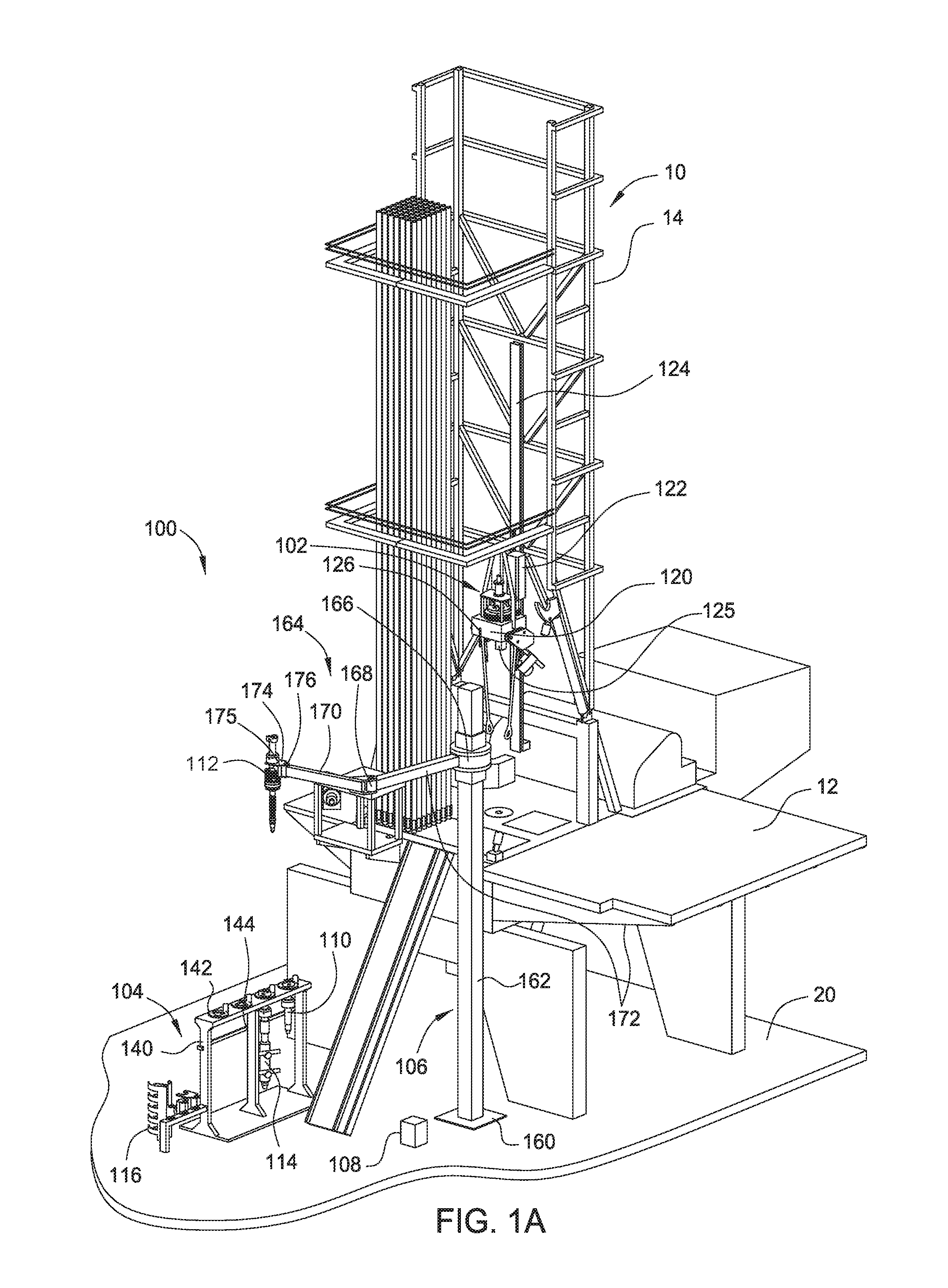
FIG. 1A schematically illustrates a modular top drive system 100 according to one embodiment of the present disclosure. The modular top drive system 100 may include a top drive unit 102, a tool storage unit 104, and a tool exchange unit 106. In one embodiment, the modular top drive system 100 may further include a central control unit 108 connected to at least one of the top drive unit 102, the tool storage unit 104, and the tool exchange unit 106. The tool exchange unit 106 may automatically position and align tools with the top drive unit 102 before installation of the tools.
The modular top drive system 100 may be used in on a drilling rig 10 to for a well operation. The top drive unit 102 may be mounted on a derrick 14 on a rig floor 12. A plurality of tools may be exchangeably attached to the top drive unit 102 to perform various operations. For example, a drilling tool 110 may be attached to the top drive unit 102 for a drilling operation, a casing tool 112 may be attached to the top drive unit 102 for a casing running operation, a cementing tool 114 may be attached to the top drive unit 102 for a cementing operation, and accessories 116 may be used to perform other operations. The tool storage unit 104 and the tool exchange unit 106 may be disposed on a deck 20. A plurality of tools, such as the drilling tool 110, the casing tool 112, the cementing tool 114, and the accessories 116, may be stored in the tool storage unit 104 when not in use. The tool exchange unit 106 is configured to transfer the plurality of tools between the tool storage unit 104 and the top drive unit 102. The plurality of tools may include a universal coupling so that each of the plurality of tools can be interchangeably connected to the top drive unit 102, stored in the tool storage unit 104, and handled by the tool exchange unit 106.
In one embodiment, one or more of the plurality of tools may include an identification device that may be used to identify the tool. In one embodiment, the identification device may also be used to store operational parameters of the tool. Even though the drilling tool 110, the casing tool 112, the cementing tool 114, and the accessories 116 are illustrated in FIGS. 1A-1C, embodiments of the present disclosure may be used to install and align any suitable tools, such as completion tools, fracturing tools, pumps, sand screens, clamping tools, internal gripping tools, external gripping tools, adaptors, or combinations thereof.
In one embodiment, at least one of the tool storage unit 104, the top drive unit 102, and the tool exchange unit 106 includes a reading device configured to interact with the tool identification device and identify the tool. In one embodiment, other tool information, such as gripping outer diameter, calibration factors, and tool dimensions, may be obtained from the tool identification device.
In one embodiment, identification of the tools from the reading device may be transmitted to the central control unit 108 by the top drive unit 102, the tool storage unit 104 or the tool exchange unit 106. The central control unit 108 may use the identification of the tools to control the operation.
The top drive unit 102 may include a coupler 120 configured to selectively connect and operate one or more tools, such as the drilling tool 110, the casing tool 112, the cementing tool 114. The top drive unit 102 may include a trolley 122 configured to couple the coupler 120 to a rail 124 on the derrick 14. In one embodiment, the top drive unit 102 may include a tool identifying device 126. The tool identifying device 126 may be configured to interact with the identification device in each tool connected to the top drive unit 102 or the identification device in each tool to be connected to the top drive unit 102.
The tool storage unit 104 may include a frame 140 and a plurality of tool receiving slots 142. Each of the tool receiving slots 142 may be configured to receive a tool. In one embodiment, the tool storage unit 104 may further include a tool identifying device 144 configured to identify tools disposed in the tool storage unit 104.
The tool exchange unit 106 may include a tool holder 174 configured to grip a tool and an actuation assembly configured to move the tool holder 174. The actuation assembly may include a base 160. The base 160 may be secured to the deck 20 of the drilling rig 10 or adjacent structures. A post 162 may extend from the base 160. The post 162 may extend vertically from the base 160 to a height above the rig floor 12 such that the tool exchange unit 106 may retrieve any of the tools from the tool storage unit 104 and deliver the retrieved tools to the top drive unit 102 and vice versa.
The tool exchange unit 106 further includes a slide hinge 166 connected to the post 162, and an arm 164 connected to the slide hinge 166. The slide hinge 166 may be connected to the post 162 by a linear actuator that moves the slide hinge 166 longitudinally along the post 162. The slide hinge 166 may also be pivotally connected to the linear actuator allowing pivoting of the arm 164 relative to the post 162. The linear actuator may include an electric slew motor, a hydraulic slew motor, or an electro-mechanical linear actuator.
The arm 164 may include an aft-arm 172, a forearm 170, and an actuated joint 168 connecting the forearm 170 and the aft-arm 172. The tool holder 174 may be releasably connected to the forearm 170. The arm 164 may further include an arm actuator (not shown) for selectively curling and extending the forearm 170 and relative to the aft-arm 172. The arm actuator may include a cylinder and a piston disposed in a bore of the cylinder. Alternatively, the arm actuator may include an electro-mechanical linear actuator, such as a motor and lead screw or pinion and gear rod, instead of the piston and cylinder assembly. Alternatively, the actuated joint may be a telescopic joint instead of an elbow.
The tool holder 174 may include a safety latch for retaining any of the tools, such as the drilling tool 110, the casing tool 112, the cementing tool 114, and the accessories 116, thereto after engagement of the holder therewith to prevent unintentional release of the units during handling thereof. Additionally, the tool holder 174 may include a brake for torsionally connecting any of the tools after engagement of the tool holder 174 therewith to facilitate connection to the top drive unit 102.
In one embodiment, the tool holder 174 may grip the tools in a fixed position so that when the tool holder 174 grips a tool, the relative position of the tool to the tool holder 174 is known. In this respect, the positioning and alignment of the tool can be achieved by positioning the tool holder 174 and aligning the tool holder 174. The tool holder 174 may be moved to any target positions by moving the slide hinge 166, the actuated joint 168, and/or other actuated components of the tool exchange unit 106.
In one embodiment, the tool exchange unit 106 may include a tool identifying device 176. The tool identifying device 176 may be disposed near the tool holder 174 to identify the tools engaged by the tool holder 174 or the tools adjacent the tool holder 174. In one embodiment, other tool information, such as gripping outer diameter, calibration factors, and tool dimensions, may be obtained through the tool identifying device 176.
In one embodiment, the tool exchange unit 106 includes a position and alignment assembly 175 configured to facilitate automatic tool installation. In one embodiment, the position and alignment assembly 175 may be configured to position the tool held by the tool exchange unit 106 near the top drive unit 102 and to align the tool with the top drive unit 102 for installation. The position and alignment assembly 175 may include one or more sensors to determine the relative location between the tool exchange unit 106 and the top drive unit 102. In one embodiment, the position and alignment assembly 175 may include separate sensors for positioning and alignment. The position and alignment assembly 175 may include one or more proximity sensors, such as optical sensors, capacitive sensors, and inductive sensors, one or more cameras, such as 2D cameras or 3D cameras.
The position and alignment assembly 175 may be connected to the central control unit 108. The central control unit 108 may receive and process sensor signals from the position and alignment assembly 175 and send control signal to the tool exchange unit 106 to achieve positioning and alignment.
In one embodiment, the top drive unit 102 may include a target assembly 125. The position and alignment assembly 175 on the tool exchange unit 106 may detect or interact with the target assembly 125 to perform tool positioning and alignment. In one embodiment, the target assembly 125 may be one or more passive markers for the position and alignment assembly 175 to visually identify. Alternatively, the target assembly 125 may include one or more passive devices configured to reflect signals back to the position and alignment assembly 175 for positioning and alignment. For example, the target assembly 125 may include one or more proximity sensors. Alternatively, the target assembly 125 may include active devices configured to actively detect the position of the tool exchange unit 106. For example, the position and alignment assembly 175 may include one or more passive markers and the active devices on the target assembly 125 may detect the passive markers and identify the position and alignment assembly 175 when the position and alignment assembly 175 moves within an operation range of the target assembly 125. In another embodiment, the position and alignment assembly 175 may include one or more passive devices configured to reflect signals back to the active devices on the target assembly 125.
Elastic deformation of the tool exchange unit 106 including the tool holder 174 may cause a tilting of the tool gripped thereon, thus leading to misalignment. Additionally, tilting of a rig (such as a sea rig) on which the top drive unit 102 is positioned may also cause misalignment between the tool and the top drive unit 102. According to embodiments of the present disclosure, the alignment assembly 175 may be used to detect and adjust relative orientations between the tool and the top drive unit 102 to prevent misalignment.
To install a particular tool on the top drive unit 102, the tool exchange unit 106 may first approach the tool storage unit 104 to identify and grip the desired tool. The tool exchange unit 106 may move the tool holder 174 in proximity to the tools in the tool storage unit 104. In one embodiment, the tool holder 174 may scan the tools in the tool storage unit 104 so that the tool identifying device 176 can identify the desired tool. Alternatively, the tool identifying device 144 in the tool storage unit 104 may provide tool identity information and tool location information to the central control unit 108. The central control unit 108 may then provide the location of the desired tool to the tool exchange unit 106.
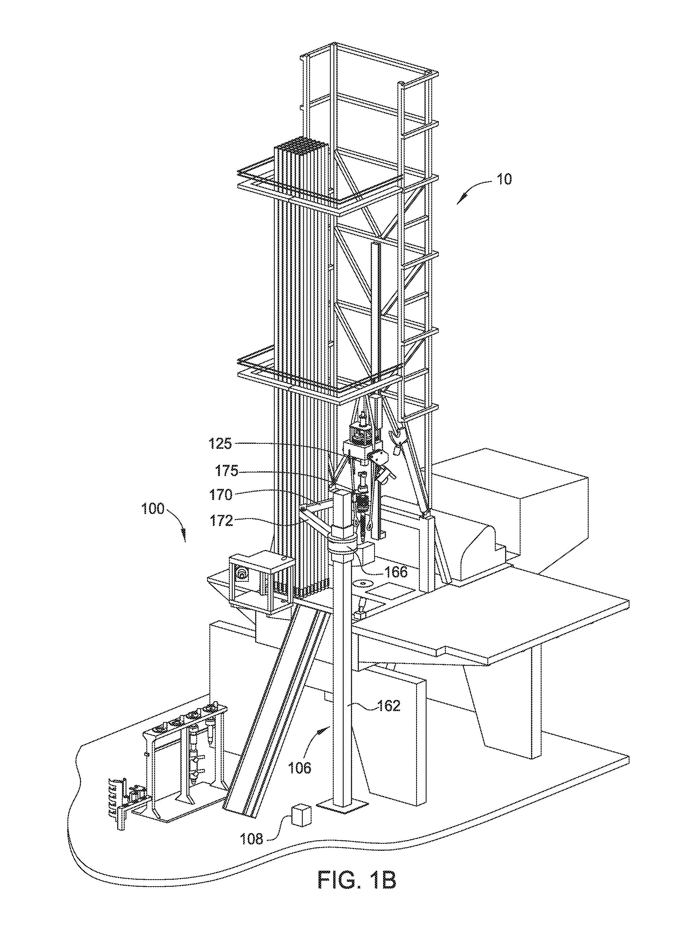
Once the tool exchange unit 106 picks up the desired tool, the tool holder 174 may move the tool towards the top drive unit 102. In FIG. 1A, the tool exchange unit 106 has picked up the tool and is moving it towards the top drive unit 102. The tool exchange unit 106 may move the tool to a location below the top drive unit 102 so that the tool can be aligned with the top drive unit 102. In FIG. 1B, the tool exchange unit 106 is a schematic view of the modular top drive system 100 at a position of tool alignment. In one embodiment, the tool may be gripped by the tool exchange unit 106 in a fixed position so that the tool is aligned with the top drive unit 102 when the tool holder 174 is aligned with the top drive unit 102. Aligning the tool may include adjusting position and/or orientation of the tool relative to the top drive unit 102. After aligning the tool with the top drive unit 102, the tool exchange unit 106 installs the tool to the top drive unit 102. FIG. 1C is a schematic view of the modular top drive system 100 in a position of tool installation.
Even though the alignment assembly 175 is shown attached to the tool exchange unit 106 in FIG. 1A-1C, the alignment assembly 175 may be attached to the top drive unit 102 or the tool being installed. Similarly, the target assembly 125 may be positioned at different locations, such as on the top drive unit 102, on the tool exchange unit 106 or on the tool, to interact with the alignment assembly 175.
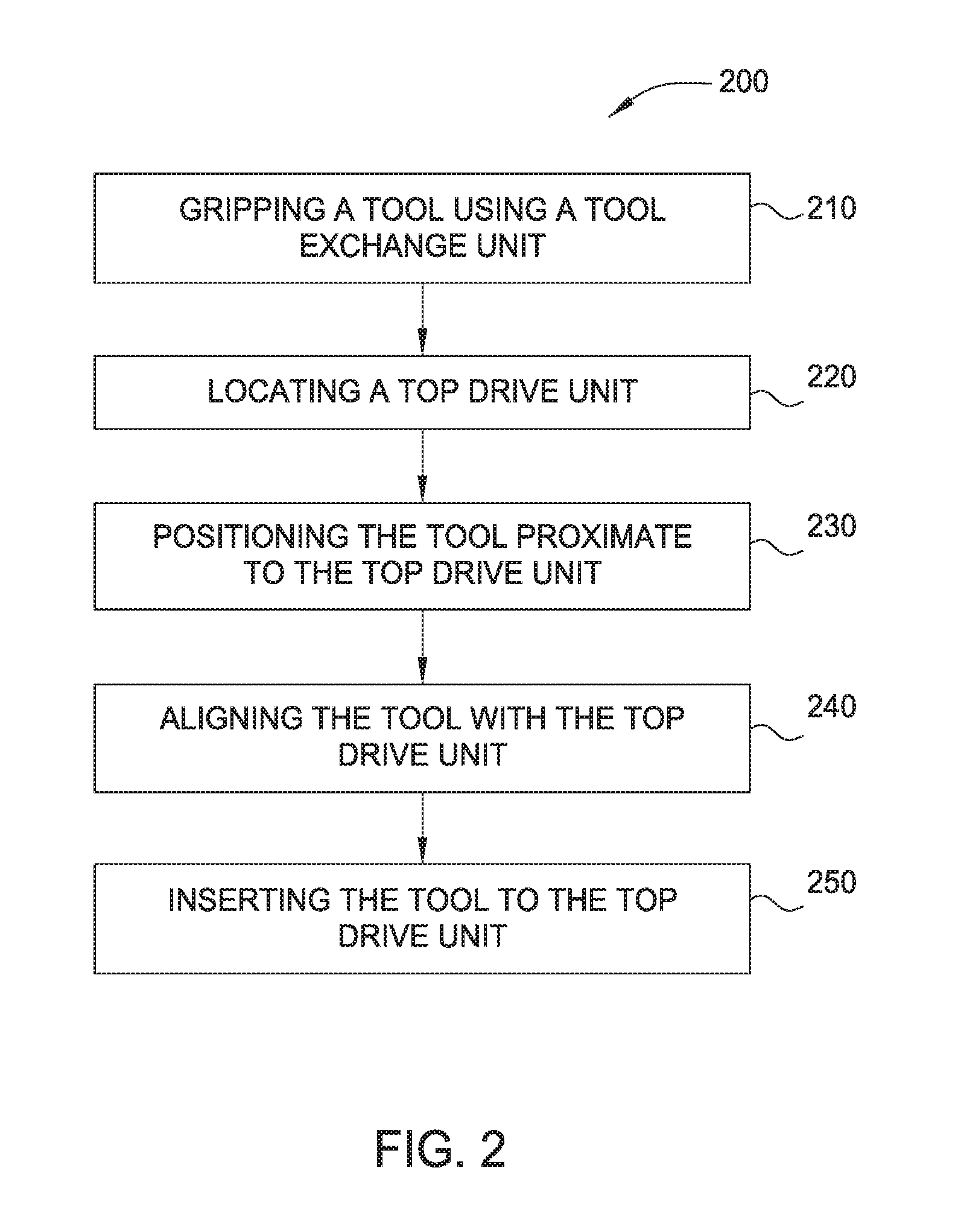
In one embodiment, tool alignment may be achieved by a two stage operation. FIG. 2 is a flow chart of a method 200 for tool positioning and installation according to one embodiment of the present disclosure.
In box 210 of the method 200, a tool is gripped by a tool handler, such as the tool exchange unit 106, configured to install the tool to a rig operating system, such as the modular top drive system 100. In one embodiment, the identity of the tool to be installed may be sent to the tool handler and the tool handler identifies the tool using a tool identifying device, such as the tool identifying device 176. In another embodiment, a location of the tool to be installed in a tool storage unit, such as the tool storage unit 104, may be provided to the tool handler so that the tool handler grips the correct tool.
In box 220 of the method 200, a tool receiving unit, such as the top drive unit 102, may be located so that the tool can be aligned with the tool receiving unit. In one embodiment, the tool receiving unit may be located using a sensor disposed on the tool receiving unit and/or on the tool handler. Exemplary sensors include but not limited to lasers, field strength sensors, ultrasound sensors, cameras, and combinations thereof. In one embodiment, the tool handler may move towards the direction of the tool receiving unit until the sensors on the tool handler detect the tool receiving unit. Alternatively, the tool handler may move towards the direction of the tool receiving unit until the sensors on the tool receiving unit detect the tool handler. In one embodiment, the tool handler, such as the tool exchange unit 106, may start at a lower point on the rig floor 12 and moves up towards the tool receiving unit, such as the top drive unit 102, until the sensors on the tool exchange unit 106 detect the top drive unit 102.
If the position of the tool receiving unit, such as the top drive unit 102, is known to a controller, such as the central control unit 108, the step of locating the top drive unit, i.e. box 220, may be omitted. For example, the vertical position of the top drive unit 102 may be known to the central control unit 108 through the position of the trolley 122 relative to the rail 124.
In box 230, when the location of the tool receiving unit is known, the tool handler may move the tool proximate the tool receiving unit to enable alignment. For example, the tool exchange unit 106 may move the tool holder 174 close to the top drive unit 102 so that the position and alignment assembly 175 and the target assembly 125 can interact with each other for alignment. Alternatively, when the tool exchange unit 106 is not down or not present, the tool may be transferred and positioned manually proximate the top drive unit 102. For example, the tool may be moved manually using a joystick.
In box 240, the tool may be aligned with the tool receiving unit for installation. In one embodiment, the tool may be aligned with the tool receiving unit by moving the tool holder and aligning the tool holder with the tool receiving unit. Aligning the tool may include adjusting position and/or orientation of the tool holder relative to the tool receiving unit. In one embodiment, the tool alignment may be performed using corresponding monitoring proximity sensors disposed on the target assembly 125 and on the position and alignment assembly 175. In another embodiment, the tool alignment may be achieved through direct contact between the target assembly 125 and the position and alignment assembly 175. In another embodiment, the tool alignment may be achieved by capturing and analyzing images from a 3D camera. The 3D camera may be disposed on the target assembly 125, on the alignment assembly 175, or any suitable location where the 3D camera has a line of sight of the alignment process. In another embodiment, the tool alignment may be achieved by capturing and analyzing images from 2D cameras. The 2D cameras may be disposed on the position and alignment assembly 175, the target assembly 125, or any suitable locations where the 2D cameras have a line of sight of the alignment process. For example, relative positions of the tool and the receiving unit may be determined by analyzing two dimensional images using triangulation or trilateration.
In box 250, after alignment, the tool may be inserted into a receiving opening in the tool receiving unit, such as the top drive unit 102, by the tool handler, such as the tool exchange unit 106 to complete installation of the tool. In one embodiment, the tool may be connected to the tool receiving unit by a locking connection, such as a bayonet connection. The receiving opening of the tool receiving unit may have an inner profile matching an outer profile of a coupling of the tool. Once the coupling of the tool is inserted through the receiving opening, the tool handler may rotate the tool to connect the tool and tool receiving unit or the drive unit may rotate to connect the tool.
FIGS. 3A-3B schematically illustrate positioning the tool exchange unit 106 relative to the top drive unit 102 according to one embodiment of the present disclosure. The positioning process shown in FIG. 3A-3B may be used to perform the tool locating step in Box 220 of the method 200. In FIG. 3A, a tool 302 is gripped by the tool exchange unit 106. The tool 302 may be a drilling tool, a casing tool, a cementing tool, or any other suitable tools that may be installed on a rig operating system. In one embodiment, the tool 302 may include a coupling 316 shaped to connect with the top drive unit 102. In one embodiment, the relative position of the coupling 316 and the tool holder 174 may be fixed when the tool 302 is gripped by the tool holder 174 so that alignment of the tool 302 with the top drive unit 102 may be achieved by aligning the tool holder 174 and the top drive unit 102.
In one embodiment, a positioning sensor 304 may be attached to the tool holder 174. The positioning sensor 304 may be configured to locate the top drive unit 102. In one embodiment, one or more redundant positioning sensor 305 may be attached to the tool holder 174. The redundant positioning sensor 305 may be used to, for example, in combination with the positioning sensor 304, to detect a tilting angle of the tool 302 on the tool holder 174. The positioning sensor 304 and the redundant positioning sensor 305 may be a laser distance sensor, a field strength sensor, an ultrasound distance sensor, a camera, or combinations thereof.
The top drive unit 102 may include a drive body 306. The drive body 306 may movably attached to a rig. For example, the drive body 306 may be movably attached to the rail 124. The top drive unit 102 may include a drive ring 308. The drive ring 308 may be movably connected to the drive body 306 by thrust bearings 310. The drive ring 308 may define a receiving opening 312 for receiving the tool 302. In one embodiment, a coupler 314 may be disposed in the receiving opening 312. The coupler 316 may be configured to connect with the coupling 316 of the tool 302. In one embodiment, the coupler 316 may be a universal connector having interfaces for transferring torque, hydraulic power, electrical power, and electrical signals.
The top drive unit 102 and the tool exchange unit 106 may be coupled to the central control unit 108. The central control unit 108 may receive sensor signals from and send control signals to the tool exchange unit 106 and the top drive unit 102 to position the tool 302 adjacent the top drive unit 102 for installation.
In FIG. 3A, the tool 302 is at a distance away from the top drive unit 102. The tool exchange unit 106 may move the tool 302 along a general direction, such as vertically upward, towards the top drive unit 102 while monitoring the signals from the positioning sensor 304. The signals from the positioning sensor 304 may be processed by the tool exchange unit 106 or sent to the central control unit 108 for processing. Once the signal from the positioning sensor 304 indicates the top drive unit 102 is within a predetermined range from the tool 302, the tool exchange unit 106 may stop moving and invoke a fine tuning procedure to align the tool 302 with the top drive unit 102. In FIG. 3B, the tool 302 has been moved up and positioned within the range for alignment.
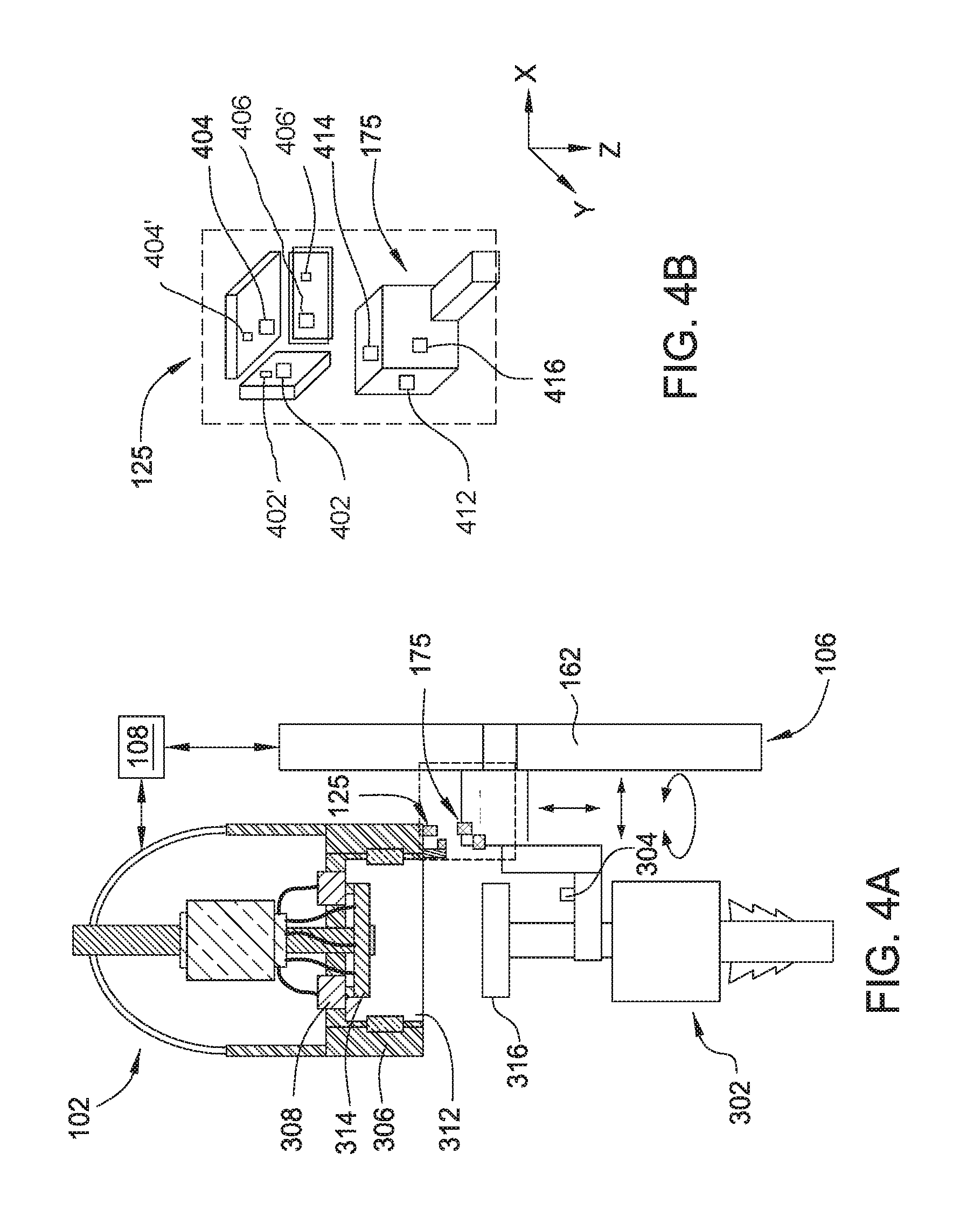
FIGS. 4A-4D schematically illustrate aligning a tool and a top drive unit using proximity sensors according to one embodiment of the present disclosure. The alignment process of FIGS. 4A-4C may be used to perform the alignment step in box 240 of the method 200.
In FIG. 4A, the tool 302 is positioned adjacent the top drive unit 102 so that the target assembly 125 on the top drive unit 102 and the position and alignment assembly 175 on the tool exchange unit 106 can interact with each other. FIG. 4B is a schematic partial enlarged view of one embodiment of the target assembly 125 and one embodiment of the position and alignment assembly 175. In one embodiment, the target assembly 125 may include proximity sensors 402, 404, 406 facing different directions. In one embodiment, the proximity sensors 402, 404, 406 may be positioned facing x, z and y axis of a Cartesian coordination system. In one embodiment, the target assembly 125 may include one or more redundant sensor 402', 404', 406' to facilitate measurement of a relative orientation between the target assembly 125 and the position and alignment assembly 175 a corresponding axis.
In one embodiment, the position and alignment assembly 175 may include reference structures corresponding to the proximity sensors 402, 404, 406 and allowing the proximity sensors 402, 404, 406 to measure corresponding distances. Alternatively, the position and alignment assembly 175 may include proximity sensors 412, 414, 416 facing directions opposite the proximity sensors 402, 404, 406 respectively.
Even though, FIG. 4B illustrates sensor pairs arranged along axis of a Cartesian coordination system, the proximity sensors may be arranged along other coordination systems, such as polar coordinate systems, cylindrical coordinate systems, spherical coordinate systems, curvilinear coordinate systems, or the likes.
The proximity sensors 402, 404, 406, 412, 414, 416 may be optical proximity sensors, capacitive proximity sensors, inductive proximity sensors, or any suitable sensors.
During alignment, the tool exchange unit 106 may move relative to the top drive unit 102 while monitoring the distance between the proximity sensors 402 and 412, the distance between the proximity sensors 404 and 414, and the distance between the proximity sensors 406 and 416. As the combined distance of the sensor pairs reduces, the tool 302 and the top drive unit 102 becomes closer to being aligned. Additionally, relative orientations may be obtained by monitoring differences between the measurement from the proximity sensors 402, 404, 406 and the redundant sensors 402', 404', 406'. The orientations may be adjusted by moving the tool exchange unit relative to the top drive unit 102 to achieve alignment.
In FIG. 4C, the tool 302 is aligned with the top drive unit 102. At the aligned position, the coupling 316 of the tool 302 may be inserted into the receiving opening 312 of the top drive unit 102.
In FIG. 4D, the tool 302 is inserted into the receiving opening 312 of the top drive unit 102. The tool 302 may be inserted by moving the tool holder 174 vertically up. In one embodiment, when at the aligned position, the tool 302 may be moved up at a predetermined distance along the vertical direction to allow the coupling 316 contact the coupler 314 and make a secure connection there between. The tool exchange unit 106 may then release the tool 302 and move away.
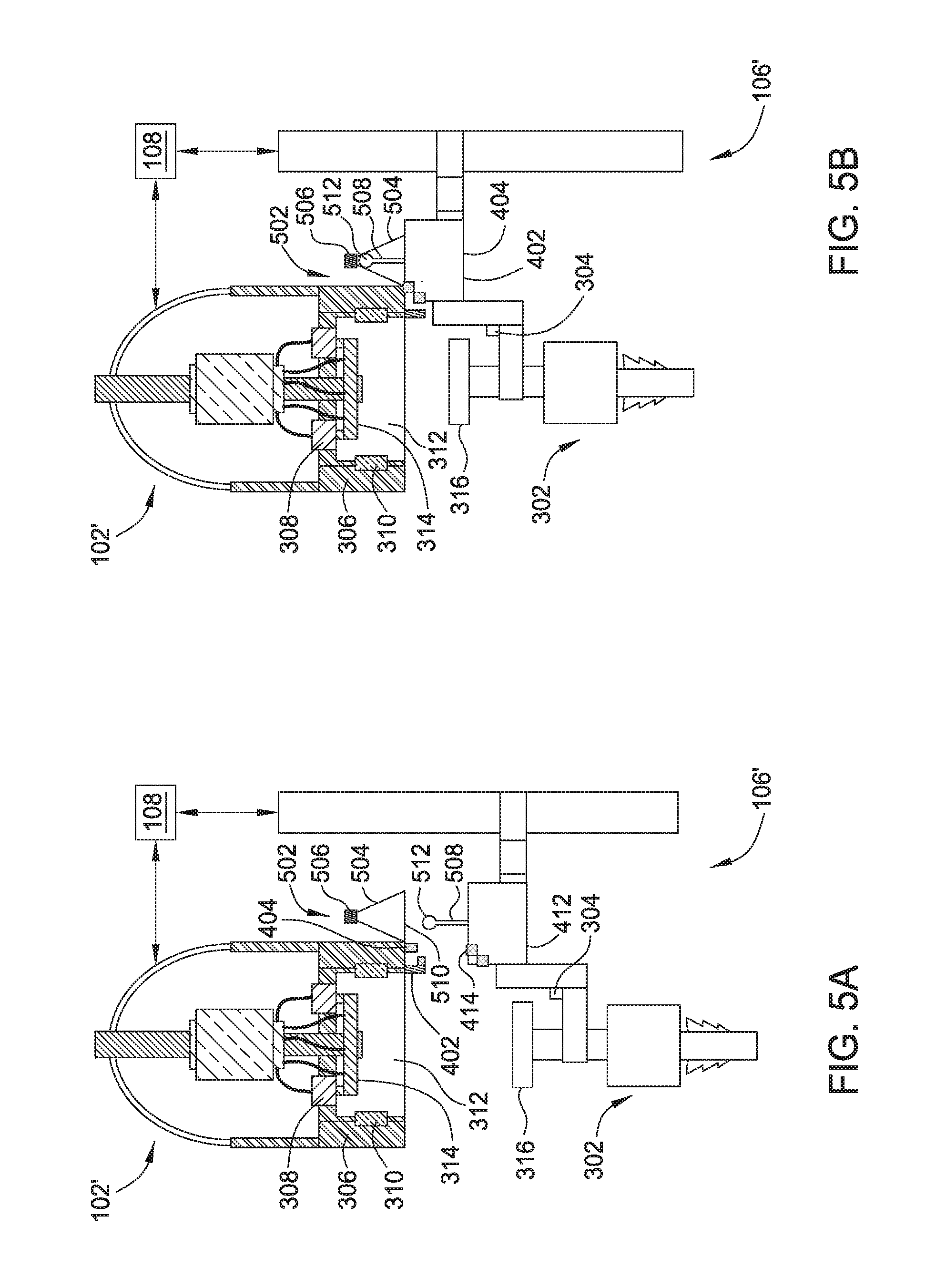
FIGS. 5A-5C schematically illustrate aligning a tool and a top drive unit using a self-alignment structure according to one embodiment of the present disclosure. The alignment process of FIGS. 5A-5B may be used to perform alignment in box 240 of the method 200. In FIGS. 5A-5C, a top drive unit 102' is aligned with the tool 302 by a tool exchange unit 106'.
The top drive unit 102' is similar to the top drive unit 102 of FIG. 4A except that the top drive unit 102' includes a self-alignment assembly 502. In one embodiment, the self-alignment assembly 502 includes a funnel 504 having an opening 510 facing down and an apex 506 at the top of the funnel 504. The opening 510 may be large enough to encompass range of displacement of the tool 302 after a rough positioning process, for example as described in the box 220 of the method 200.
The tool exchange unit 106' is similar to the tool exchange unit 106 of FIG. 4A except that the tool exchange unit 106' includes an alignment structure, such as an alignment pole 508. In one embodiment, the alignment pole 508 may extend from the tool holder 174 so that the relative position of the tool 302 and the alignment pole 508 is fixed. The alignment pole 508 may extend upward towards the top drive unit 102'. When the top drive unit 102' is located by the tool exchange unit 106', such as by process in box 220 of the method 200, the alignment pole 508 may be within the coverage of the opening 510 of the funnel 504. A top 512 of the alignment pole 508 may reach the apex 506 when the tool exchange unit 106' moves up relative to the top drive unit 102'. In one embodiment, the top 512 may include a sensor configured to detect a contact between the top 512 and the funnel 504.
As shown in FIG. 5A, after locating the top drive unit 102', the tool exchange unit 106' may move up with the tool 302 to insert the alignment pole 508 into the funnel 504. As the tool exchange unit 106' moves up, correction movements may be made to avoid contact between the top 512 and the funnel 504. In one embodiment, the sensor on the top 512 may be monitored for any potential contact. The tool exchange unit 106' may move up with corrections until the top 512 contacts or reaches a predetermined proximity with the apex 506 as shown in FIG. 5B.
In FIG. 5B, the tool 302 is aligned with the top drive unit 102'. In FIG. 5C, the tool 302 is moved up along the vertical direction by the tool exchange unit 106' and inserted in to the top drive unit 102'. In one embodiment, when at the aligned position, the tool 302 may be moved up at a predetermined distance along the vertical direction to allow the coupling 316 contact the coupler 314 and make a secure connection there between. The tool exchange unit 106' may then release the tool 302 and move away.
In one embodiment, redundant sensors, such as proximity sensors in three dimensions, and or cameras, may be attached to the top drive unit 102' and/or the tool exchange unit 106 to prevent collision between the alignment pole 508 and the funnel 504.
FIG. 6 schematically illustrates aligning the tool 302 and a top drive unit 102'' using a three-dimensional camera. The alignment of FIG. 6 may be used to achieve the alignment of box 240 in the method 200.
The top drive unit 102'' is similar to the top drive unit 102 of FIG. 4A except that the top drive unit 102'' includes a 3D camera 602 positioned to capture images of the tool 302 positioned below the top drive unit 102''. The images of the tool 302 may be sent to the central control unit 108. The central control unit 108 may analyze the 3D images, for example, using a software program, to determine the position and/or orientation of the tool 302. For example, a distance 604 along z direction between the coupling 316 and the top drive unit 102'' may be determined from analyzing the 3D images of the coupling 316. Additionally, distances between a central axis 606 of the top drive unit 102'' and a central axis 608 of the tool 302 along the x and y directions may be determined. The tool exchange unit 106 may move the tool 302 along x, y, and z direction to reduce the distances and/or adjust the orientation. Once the distances along x, y, z directions are within predetermined values, the tool 302 is aligned with the top drive unit 102''.
Alternatively, the 3D camera 602 may be attached to the tool holder 174 and positioned to capture 3 dimensional images of the top drive unit 102''. The central control unit 108 may analyze 3D images of the top drive unit 102'' to decide the distances for alignment.
The 3D camera 602 may be any suitable camera or camera systems that capable of capturing 3 dimensional images. In one embodiment, the 3D camera 602 is a time-of-flight camera.
FIG. 7 schematically illustrates aligning the tool 302 and a top drive unit 102''' using 2-dimensional cameras. The alignment of FIG. 7 may be used to achieve the alignment of box 240 in the method 200.
The top drive unit 102''' is similar to the top drive unit 102 of FIG. 4A except that the top drive unit 102''' includes two or more 2D cameras 702, 704 positioned to capture images of the tool 302 below the top drive unit 102''' from different angles. In one embodiment, the cameras 702, 704 may be disposed at opposite sides of the central axis 606 of the top drive unit 102''' so that the images captured from the cameras 702, 704 are from different angles.
Each of the cameras 702, 704 may take an image of the tool 302 at the same position, and send to the image to the central control unit 108. The central control unit 108 may analyze the images from the cameras 702, 704, for example, using a software program, to determine the position of the tool 302. In one embodiment, triangulation may be used to analyze the images from different cameras 702, 704 to determine the location of the tool 302. Alternatively, trilateration may be used to analyze images from different cameras 702, 704 to determine the location and/or orientation of the tool. In one embodiment, distances between the coupling 316 and the top drive unit 102''' along x, y, z directions may be determined from analyzing the images of the coupling 316 from different cameras 702, 704. The tool exchange unit 106 may move the tool 302 along x, y, and z direction to reduce the distances and/or adjust the orientation. Once the distances along x, y, z directions are within predetermined values, the tool 302 is aligned with the top drive unit 102'''.
Alternatively, two or more cameras may be attached to the tool holder 174 and positioned to capture images of the top drive unit 102''' from different angles. The central control unit 108 may analyze images of the top drive unit 102''' to decide the distances for alignment.
Embodiments of the present disclosure provide a modular top drive system. The modular top drive system includes a top drive unit for selectively connecting to a tool, and an alignment assembly configured to detect a position of the top drive unit relative to the tool.
In one or more embodiments, the modular top drive system further includes a tool exchange unit configured to move the tool relative the top drive unit.
In one or more embodiments, the alignment assembly is disposed on a tool holder of the tool exchange unit.
In one or more embodiments, the alignment assembly comprises first, second, and third proximity sensors attached to the tool exchange unit, and fourth, fifth, and sixth proximity sensors attached to the top drive unit and corresponding to the first, second, third proximity sensors respectively.
In one or more embodiments, the first, second, and third proximity sensors are disposed along x, y, z axis of a Cartesian coordinate system, and the fourth, fifth, and sixth proximity sensors are disposed along x, y, z of the Cartesian coordinate system respectively.
In one or more embodiments, the alignment assembly comprises two or more proximity sensors disposed along a coordinate system, and the top drive unit comprises two or more proximity sensors disposed along the same coordinate system.
In one or more embodiments, the coordinate system is selected from a polar coordinate system, a cylindrical coordinate system, a spherical coordinate system, a curvilinear coordinate system, or the likes.
In one or more embodiments, the alignment assembly comprises a self-alignment structure.
In one or more embodiments, the self-alignment structure includes a funnel attached to the top drive unit, and an alignment pole attached to the tool exchange unit, wherein the alignment pole is configure to insert into the funnel and reach an apex of the funnel.
In one or more embodiments, the modular top drive further includes a sensor disposed on a top of the alignment pole.
In one or more embodiments, the modular top drive further includes one or more proximity sensors disposed on the top drive unit and the tool exchange unit to prevent collision.
In one or more embodiments, the modular top drive further includes one or more proximity sensors disposed on the top drive unit and the tool exchange unit to prevent collision.
In one or more embodiments, the alignment assembly comprises a three dimensional camera.
In one or more embodiments, the alignment assembly comprises two or more two dimensional cameras.
In one or more embodiments, the modular top drive further includes a positioning device configured to position the tool within an operational range of the alignment assembly.
In one or more embodiments, the positioning device comprises one of a laser sensor, a field strength sensor, an ultrasound sensor, a camera, and a combination thereof.
In one or more embodiments, the modular top drive further includes an identification reader configured to obtain identity information from identification devices on tools.
In one or more embodiments, the top drive unit is configured to selectively connect a drilling tool, a casing tool, a cementing tool, a completion tool, a fracturing tool, a pump, a sand screen, a clamping tool, an internal gripping tool, an external gripping tool, an adaptor, or a combination thereof.
Embodiments of the present disclosure provide a top drive unit for construction of a wellbore. The top drive unit includes a drive body, a drive ring movably connected the drive body, a coupler connected to the drive ring, wherein the coupler is configured to connect with a coupling of a tool, and an alignment assembly configured to align the coupling of the tool with the coupler.
In one or more embodiments, the alignment assembly comprises a three dimensional camera attached to the drive body.
In one or more embodiments, the alignment assembly comprises two or more two dimensional cameras attached to the drive body.
In one or more embodiments, the alignment assembly comprises a self-alignment structure attached to the drive body.
In one or more embodiments, the self-alignment structure comprises a funnel.
In one or more embodiments, the alignment assembly comprises three or more proximity sensors.
Embodiments of the present disclosure further provide a tool exchange unit configured to install a tool to a top drive unit. The tool exchange unit includes a tool holder configured to grip the tool, an actuation assembly configured to move the tool holder, and an alignment assembly to detect a location of the top drive unit relative to the tool gripped by the tool holder.
In one or more embodiments, the alignment assembly comprises a three dimensional camera.
In one or more embodiments, the alignment assembly comprises two or more two dimensional cameras.
In one or more embodiments, the alignment assembly comprises a self-alignment structure.
In one or more embodiments, the self-alignment structure comprises an alignment pole configured to insert to a funnel.
In one or more embodiments, the alignment assembly comprises three or more proximity sensors.
Embodiments of the present disclosure further provide a method for operating a top drive system. The method includes retrieving a tool using a tool exchange unit, aligning the tool with a top drive unit using an alignment assembly, and inserting the tool into the top drive unit.
In one or more embodiments, the method further includes positioning the tool proximate the top drive unit.
In one or more embodiments, positioning the tool proximate the top drive unit comprises moving the tool within a range of the alignment assembly.
In one or more embodiments, positioning the tool proximate the top drive unit comprises positioning the tool at a height within a predetermined distance from a height of the top drive unit.
In one or more embodiments, aligning the tool with the top drive unit comprises monitoring distances between proximity sensors mounted on the top drive unit and proximity sensors mounted on the tool exchange unit, and moving the tool exchange unit to reduce the distances.
In one or more embodiments, aligning the tool with the top drive unit comprises moving up the tool exchange unit to insert an aligning pole into a funnel, and monitoring a distance between the aligning pole and the funnel and correcting the upward movement of the tool exchange unit to avoid contact between the alignment pole and the funnel.
In one or more embodiments, aligning the tool with the top drive unit comprises capturing three dimensional images of the top drive unit or the tool, analyzing the three dimensional images to determine distances between the top drive unit and the tool, and moving the tool exchange unit to reduce the distances.
In one or more embodiments, aligning the tool with the top drive unit comprises capturing two dimensional images of the top drive unit or the tool from different angles, analyzing the two dimensional images from different angels to determine distances between the top drive unit and the tool, and moving the tool exchange unit to reduce the distances.
In one or more embodiments, the method further includes, prior to positioning the tool proximate the top drive unit, locating the top drive unit using a positioning device.
Even though the above disclosure describes tool positioning devices and tool alignment assemblies disposed on a top drive unit or a tool exchange unit, embodiments of the present disclosure encompasses tool positioning device and tool alignment assemblies disposed entirely or partially on a tool to be installed.
Even though the above disclosure describes apparatus and method for aligning drilling tools, casing tools, and cementing tools with a top drive, the present disclosure encompasses apparatus and method for aligning any suitable tools, such as completion tools, fracturing tools, pumps, sand screens, clamping tools, internal gripping tools, external gripping tools, adaptors, or combinations thereof.
While the foregoing is directed to embodiments of the present disclosure, other and further embodiments of the disclosure may be devised without departing from the basic scope thereof, and the scope of the invention is determined by the claims that follow.
* * * * *
References
D00000
D00001
D00002
D00003
D00004
D00005
D00006
D00007
D00008
D00009
D00010
D00011
XML
uspto.report is an independent third-party trademark research tool that is not affiliated, endorsed, or sponsored by the United States Patent and Trademark Office (USPTO) or any other governmental organization. The information provided by uspto.report is based on publicly available data at the time of writing and is intended for informational purposes only.
While we strive to provide accurate and up-to-date information, we do not guarantee the accuracy, completeness, reliability, or suitability of the information displayed on this site. The use of this site is at your own risk. Any reliance you place on such information is therefore strictly at your own risk.
All official trademark data, including owner information, should be verified by visiting the official USPTO website at www.uspto.gov. This site is not intended to replace professional legal advice and should not be used as a substitute for consulting with a legal professional who is knowledgeable about trademark law.