Insulation dam for buried ducts and buried duct insulation depth indicator
Marden , et al. No
U.S. patent number 10,465,380 [Application Number 15/708,211] was granted by the patent office on 2019-11-05 for insulation dam for buried ducts and buried duct insulation depth indicator. This patent grant is currently assigned to Owens Corning Intellectual Capital, LLC. The grantee listed for this patent is Owens Corning Intellectual Capital, LLC. Invention is credited to Craig Marden, Mark H. Smith.


| United States Patent | 10,465,380 |
| Marden , et al. | November 5, 2019 |
Insulation dam for buried ducts and buried duct insulation depth indicator
Abstract
An insulation dam is provided that facilitates placement and retention of loosefill insulation over a duct. Additionally, a depth indicator is provided that facilitates placement of a proper depth of the loosefill insulation over the duct.
| Inventors: | Marden; Craig (Shutesbury, MA), Smith; Mark H. (Newark, OH) | ||||||||||
|---|---|---|---|---|---|---|---|---|---|---|---|
| Applicant: |
|
||||||||||
| Assignee: | Owens Corning Intellectual Capital,
LLC (Toledo, OH) |
||||||||||
| Family ID: | 61617910 | ||||||||||
| Appl. No.: | 15/708,211 | ||||||||||
| Filed: | September 19, 2017 |
Prior Publication Data
| Document Identifier | Publication Date | |
|---|---|---|
| US 20180080224 A1 | Mar 22, 2018 | |
Related U.S. Patent Documents
| Application Number | Filing Date | Patent Number | Issue Date | ||
|---|---|---|---|---|---|
| 62396868 | Sep 20, 2016 | ||||
| Current U.S. Class: | 1/1 |
| Current CPC Class: | F24F 13/0263 (20130101); E04B 1/7658 (20130101); E04B 1/7604 (20130101) |
| Current International Class: | E04B 1/76 (20060101); F24F 13/02 (20060101) |
| Field of Search: | ;52/742.13 |
References Cited [Referenced By]
U.S. Patent Documents
| 2629140 | February 1953 | MacMillan |
| 2700633 | January 1955 | Bovenkerk |
| 2989790 | June 1961 | Brown |
| 3543804 | December 1970 | Ziegler |
| 3575234 | April 1971 | Diecknnann |
| 3641724 | February 1972 | Palmer |
| 3772840 | November 1973 | Hala |
| 3915477 | October 1975 | Timmons |
| 4095454 | June 1978 | Fisher |
| 4134242 | January 1979 | Musz |
| 4272935 | June 1981 | Lukas |
| 4275541 | June 1981 | Orals |
| 4290247 | September 1981 | Alderman |
| 4337602 | July 1982 | King |
| 4471591 | September 1984 | Jamison |
| 4829738 | May 1989 | Moss |
| 5024033 | June 1991 | Anderson |
| 5197251 | March 1993 | Krysak |
| 5267422 | December 1993 | Crall, Jr. |
| 5365716 | November 1994 | Munson |
| 5389167 | February 1995 | Sperber |
| 5731359 | March 1998 | Moser |
| 5819496 | October 1998 | Sperber |
| 5988264 | November 1999 | Goldsmith |
| 6088968 | July 2000 | Williston, Jr. |
| 6112490 | September 2000 | Meyer |
| 6128884 | October 2000 | Berdan, II |
| 6226943 | May 2001 | Grinshpun |
| 6604993 | August 2003 | Boniface |
| 6858280 | February 2005 | Allen |
| 6935379 | August 2005 | Buchanan, Sr. |
| 7641461 | January 2010 | Khoshnevis |
| 8117786 | February 2012 | Tobbe |
| 8438789 | May 2013 | Uhl |
| 8590229 | November 2013 | Taylor |
| 8850752 | October 2014 | Graboski |
| 8931215 | January 2015 | Cook |
| 8943767 | February 2015 | Lewis |
| 9222265 | December 2015 | Richmond |
| 9309663 | April 2016 | Fay |
| 9587397 | March 2017 | McCary, Sr. |
| 9822526 | November 2017 | Cook |
| 9938711 | April 2018 | Grisolia |
| 9951969 | April 2018 | Combs |
| 10234168 | March 2019 | Minter |
| 10309682 | June 2019 | Combs |
| 2008/0202041 | August 2008 | Dillon |
| 2009/0044797 | February 2009 | Klement |
| WO-8302491 | Jul 1983 | WO | |||
Other References
|
"Attics" Jul. 25, 2013 https://web.archive.org/web/20130725031509/http://www.bobandeva.com/rjc/a- ttics.htm(Year: 2013). cited by examiner. |
Primary Examiner: Maestri; Patrick J
Assistant Examiner: Sadlon; Joseph J.
Attorney, Agent or Firm: Calfee, Halter & Griswold LLP
Parent Case Text
CROSS REFERENCE TO RELATED APPLICATION
This application claims priority to and any benefit of U.S. Provisional Application No. 62/396,868, filed Sep. 20, 2016, the entire content of which is incorporated herein by reference
Claims
The invention claimed is:
1. A method of applying loosefill insulation in an enclosed space including a duct, the method comprising the ordered steps of: mounting a depth indicator on the duct, said depth indicator comprising a base and a vertical member extending from the base, wherein the base affixes the depth indicator to the duct, and wherein a first continuous length of the vertical member is a first color and a second continuous length of the vertical member is a second color; blowing loosefill insulation into the enclosed space so that the loosefill insulation reaches a first height in the enclosed space adjacent to the duct and a second height in the enclosed space over the duct; and determining the loosefill insulation has reached the second height when the second color is no longer visible, wherein a total length of the vertical member is equal to a sum of the first length and the second length, and wherein at least one of the first length and the second length is equal to or greater than half of the total length.
2. The method of claim 1, wherein the base includes an adhesive for attaching the depth indicator to the duct.
3. The method of claim 1, wherein the vertical member is centered on and extends perpendicular to an outer surface of the duct.
4. The method of claim 1, wherein the vertical member is made of foam.
5. The method of claim 1, wherein the enclosed space is an attic.
6. The method of claim 1, wherein a width of the base is greater than a width of the vertical member.
Description
FIELD
The general inventive concepts relate to fiber insulation and, more particularly, to structure for facilitating application of loosefill insulation around existing ductwork.
BACKGROUND
Most buildings include some form of ductwork. For example, many buildings include HVAC ducts, such as in an attic of the building. It is known to cover these ducts with loosefill insulation, which is a type of insulation commonly used in attics. However, there is an unmet need for methods of and systems for easily and accurately insulating ducts (e.g., HVAC ducts) with loosefill insulation.
SUMMARY
The general inventive concepts relate to and contemplate methods of, systems for, and related structure for facilitating application of loosefill insulation (e.g., fiberglass loosefill insulation) around ducts.
In a first exemplary embodiment, an insulation dam (and a system of using such) is provided that facilitates placement and retention of loosefill insulation over a duct. Additionally, a method of applying loosefill insulation in an enclosed space including at least one duct is provided. The method comprises: erecting a first insulation dam on a first side of the duct; erecting a second insulation dam on a second side of the duct; and blowing loosefill insulation into the enclosed space, wherein a portion of the loosefill insulation is held in place between the first insulation dam and the second insulation dam, and wherein an average height of the loosefill insulation located between the first insulation dam and the second insulation dam is greater than an average height of the loosefill insulation not located between the first insulation dam and the second insulation dam.
In some embodiments, the first insulation dam comprises a plurality of first support members and a material that connects to each of the first support members. In some embodiments, each first support member is a rigid post that is spaced from the duct and extends vertically from a surface on which the duct rests. In some embodiments, the surface is a floor. In some embodiments, the material is one of a film, a fabric, and a net.
In some embodiments, the second insulation dam comprises a plurality of second support members and a material that connects to each of the second support members. In some embodiments, each second support member is a rigid post that is spaced from the duct and extends vertically from a surface on which the duct rests. In some embodiments, the surface is a floor. In some embodiments, the material is one of a film, a fabric, and a net.
In some embodiments, the first insulation dam and the second insulation dam are substantially aligned with one another, albeit on opposite sides of the duct.
In some embodiments, the first insulation dam and the second insulation dam each extend a length of the duct to be insulated.
In some embodiments, the enclosed space is an attic.
In some embodiments, the duct is a flexible duct.
In a second exemplary embodiment, a depth indicator (and a system of using such) is provided that facilitates placement of a proper depth of loosefill insulation over a duct. Additionally, a method of applying loosefill insulation in an enclosed space including at least one duct is provided. The method comprises: mounting a depth indicator on a portion of the duct, said depth indicator including indicia thereon; blowing loosefill insulation into the enclosed space so that the portion of the duct is covered by the loosefill insulation; and using the indicia on the depth indicator to determine when a sufficient amount of the loosefill insulation is situated above the portion of the duct.
In some embodiments, the depth indicator comprises a base and vertical member extending from the base. In some embodiments, the base includes an adhesive for attaching the depth indicator to the duct. In some embodiments, a first portion of the vertical member has a first color and a second portion of the vertical member has a second color, wherein the indicia comprises the transition from the first color to the second color. In some embodiments, the vertical member is centered on and extends perpendicular to an outer surface of the duct. In some embodiments, the vertical member is made of foam.
In some embodiments, the enclosed space is an attic.
In some embodiments, the duct is a flexible duct.
Numerous other aspects, advantages, and/or features of the general inventive concepts will become more readily apparent from the following detailed description of exemplary embodiments, from the claims, and from the accompanying drawings being submitted herewith.
BRIEF DESCRIPTION OF THE DRAWINGS
The general inventive concepts, as well as embodiments and advantages thereof, are described below in greater detail, by way of example, with reference to the drawings in which:
FIG. 1 is a diagram showing an HVAC system and its associated ductwork for a home, according to one exemplary embodiment.
FIG. 2 is a cross-sectional view of a duct covered by loosefill insulation, according to one exemplary embodiment.
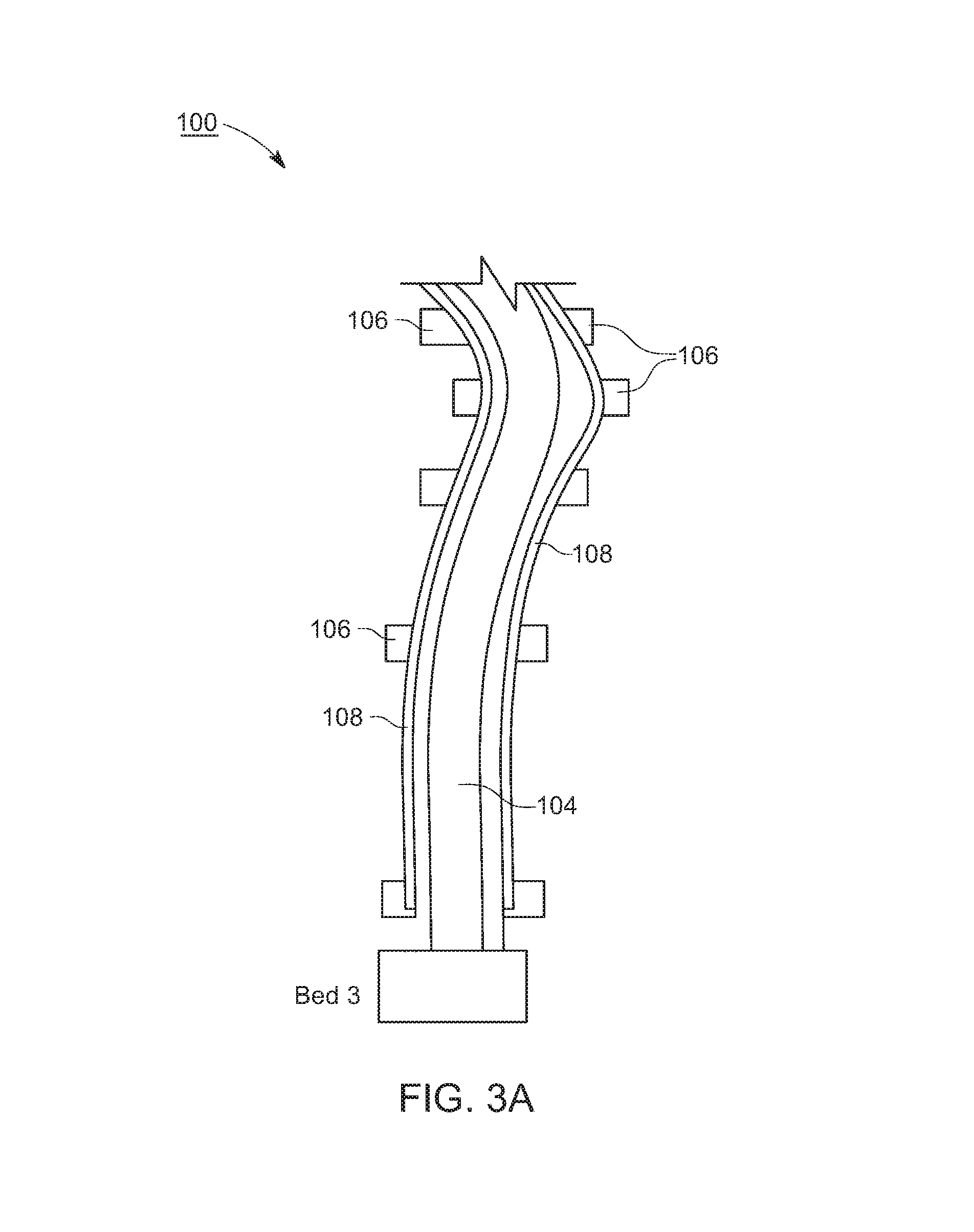
FIG. 3A is a plan view of an insulation dam formed around a duct to be insulated, according to one exemplary embodiment.
FIG. 3B is a cross-sectional view of an insulation dam formed around a duct to be insulated, according to one exemplary embodiment.
FIG. 4 is a cross-sectional view of a duct covered by loosefill insulation with a depth indicator mounted thereon, according to one exemplary embodiment.
FIG. 5 is an image of a depth indicator, according to an exemplary embodiment.
FIG. 6 is an image of the depth indicator of FIG. 5 mounted on a flexible duct to which application of loosefill insulation has begun.
DETAILED DESCRIPTION
While the general inventive concepts are susceptible of embodiment in many different forms, there are shown in the drawings, and will be described herein in detail, specific embodiments thereof with the understanding that the present disclosure is to be considered as an exemplification of the principles of the general inventive concepts. Accordingly, the general inventive concepts are not intended to be limited to the specific embodiments illustrated herein.
Burying or otherwise covering HVAC ducts, such as those commonly found in an unconditioned attic, with a quantity of loosefill insulation can significantly improve the energy performance of the HVAC system. An exemplary HVAC system and its associated ductwork for a home is shown in FIG. 1. In some exemplary embodiments, the loosefill insulation is fiberglass loosefill insulation.
In general, the loosefill insulation must be mounded over the ducts to a level l.sub.2 that exceeds the standard attic insulation level l.sub.1, in order to achieve the aforementioned energy benefits. An exemplary duct covered by a bed of loosefill insulation extending above the standard attic insulation level l.sub.1 is shown in FIG. 2.
Given its free-flowing nature, getting the loosefill insulation to cover the duct and stay there, so as to form a mound of sufficient height, is not an easy task. Accordingly, in a first exemplary embodiment, an insulation dam 100 is provided that facilitates placement and retention of loosefill insulation 102 over a duct 104.
The insulation dam 100 is created on each side of the duct 104 to be covered and extends along a length of the duct 104. For example, vertical posts (e.g., stakes 106) are situated along the length of the duct 104 to be insulated. This can be seen in FIG. 3A, where five (5) pairs of stakes 106 are situated on each side of the duct 104 to be insulated. The stakes 106 can be anchored in any suitable manner, such as by attachment to the attic/roof framing so as to follow the path of the duct or existing roof framing members (e.g., truss webs).
The stakes 106 support a material (e.g., from a rollable sheet of material) on each side of the duct, thereby forming the "walls" 108 of the insulation dam 100 on each side of the duct 104. This can be seen in FIGS. 3A and 3B. Any suitable material can be used to form the walls 108, such as fabric, netting, etc.
The walls 108 of the insulation dam 100 form a barrier on each side of the duct 104 that traps the loosefill insulation 102 being applied thereon, thereby facilitating creation of a mound of the loosefill insulation 102 having a desired height. Furthermore, because the mound of loosefill insulation 102 can be concentrated over the duct 104, via the insulation dam 100, application of excess loosefill insulation (i.e., waste) can be minimized.
The size (i.e., height) of the insulation dam 100 can be readily varied by changing the height of the stakes 106 and/or the walls 108. Likewise, a width of the insulation dam 100 can be varied by changing the distance the stakes 106 are placed relative to the duct 104 to be insulated. In this manner, a desired insulation profile can be readily tuned.
As noted above, in general, the loosefill insulation 102 must be mounded over the duct 104 to a level l.sub.2 that exceeds the standard attic insulation level l.sub.1, as shown in FIG. 2, in order to achieve performance benefits/energy savings. In other words, a height of the additional loosefill insulation 102 directly above the duct 104 is approximately equal to (l.sub.2-l.sub.1). However, once application of the loosefill insulation 102 commences, the duct 104 quickly becomes submerged in the loosefill insulation 102 and cannot be seen. Consequently, it is not easy to accurately assess a depth of the loosefill insulation 102 that extends above the duct 104. Accordingly, in a second exemplary embodiment, a depth indicator 200 is provided that facilitates placement of a proper depth d of the loosefill insulation 102 over the duct 104.
The depth indicator 200, according to an exemplary embodiment, is a flag, marker, or the like that can be mounted on top of the duct 104 prior to blowing the loosefill insulation 102 thereon. The depth indicator 200 allows for easy locating of the ducts (e.g., the duct 104) within the loosefill insulation 102 and accurate assessment of the current depth of the loosefill insulation 102 over the duct 104. For example, as shown in FIG. 4, a duct 104 with a depth indicator 200 mounted thereon could be used to cover the duct 104 with a desired quantity of the loosefill insulation 102.
A depth indicator 200, according to an exemplary embodiment, is shown in FIG. 5 prior to being mounted on a duct 104. The depth indicator 200 includes a base/saddle 202 for mounting the depth indicator 200 to the duct 104. The base/saddle 202 can be made of a semi-rigid material (e.g., cardboard). Any suitable means for mounting or otherwise attaching the base/saddle 202 to the duct 104 can be used. In one exemplary embodiment, the base/saddle 202 includes tape on opposite edges, at least a portion of each piece of tape being used to adhere the base/saddle 202 to the duct 104.
Extending from the base/saddle is a pin, nail, or the like (not shown) upon which a foam stick 204 is impaled. For example, the pin could be taped to the base/saddle. The foam stick 204 can have any desired dimensions (e.g., 1 inch.times.1 inch.times.a length suitable for the desired insulation depth). The foam stick 204 has indicia 206 thereon that facilitates placement of a proper depth of the loosefill insulation over the duct. In one exemplary embodiment, the indicia 206 on the foam stick 204 includes two visibly distinct colors (e.g., pink and black). The pink section 208 forms the lower part of the foam stick 204, while the black section 210 forms the upper part of the foam stick 204. In some exemplary embodiments, the foam stick 204 is formed of one of the two colors, with a relevant portion of the foam stick 204 being painted the other color. The pink section 208 should be immersed in the loosefill insulation 102 and the black section 210 should remain exposed. The demarcation 212 between the two colors is set to correspond to the proper fill depth d for the loosefill insulation 102, which can be easily, visibly tracked by the installer blowing the loosefill insulation 102. In this manner, as long as the installer sees any portion of the pink section 208 of the foam stick 204, the installer knows to keep applying the loosefill insulation 102 over the duct 104.
FIG. 6 shows the depth indicator 200 of FIG. 5 mounted on a flexible duct to which application of loosefill insulation has begun.
It will be appreciated that the length of the foam stick 204 forming the depth indicator 200 (or application of the relevant indicia 206 thereon) may vary depending on the size of the duct and its associated R-value. Furthermore, other forms of the indicia 206 can be used without departing from the spirit and scope of the general inventive concepts. In general, any form of indicia can be used that allows an installer to readily identify when a sufficient level of loosefill insulation has been mounded above a duct to be insulated. For example, the indicia 206 might involve numbered lines (similar to a ruler) to indicate current fill depth.
The general inventive concepts relate to and contemplate methods of, systems for, and related structure for facilitating application of loosefill insulation around ducts. The related structure can include embodiments of the insulation dam and/or the depth indicator described herein. The methods of and/or system for facilitating application of loosefill insulation around ducts can use the insulation dam and/or the depth indicator described herein.
The scope of the general inventive concepts presented herein are not intended to be limited to the particular exemplary embodiments shown and described herein. From the disclosure given, those skilled in the art will not only understand the general inventive concepts and their attendant advantages, but will also find apparent various changes and modifications to the methods and systems disclosed. It is sought, therefore, to cover all such changes and modifications as fall within the spirit and scope of the general inventive concepts, as described and/or claimed herein, and any equivalents thereof.
* * * * *
References
D00000
D00001
D00002
D00003
D00004
D00005
D00006
D00007
XML
uspto.report is an independent third-party trademark research tool that is not affiliated, endorsed, or sponsored by the United States Patent and Trademark Office (USPTO) or any other governmental organization. The information provided by uspto.report is based on publicly available data at the time of writing and is intended for informational purposes only.
While we strive to provide accurate and up-to-date information, we do not guarantee the accuracy, completeness, reliability, or suitability of the information displayed on this site. The use of this site is at your own risk. Any reliance you place on such information is therefore strictly at your own risk.
All official trademark data, including owner information, should be verified by visiting the official USPTO website at www.uspto.gov. This site is not intended to replace professional legal advice and should not be used as a substitute for consulting with a legal professional who is knowledgeable about trademark law.