Medical composite material, method for fabricating the same and applications thereof
Tsau , et al. No
U.S. patent number 10,463,500 [Application Number 14/585,894] was granted by the patent office on 2019-11-05 for medical composite material, method for fabricating the same and applications thereof. This patent grant is currently assigned to INDUSTRIAL TECHNOLOGY RESEARCH INSTITUTE. The grantee listed for this patent is INDUSTRIAL TECHNOLOGY RESEARCH INSTITUTE. Invention is credited to Jibin Horng, Hongjen Lai, Chingchih Lin, Hsinhsin Shen, Peiyi Tsai, Fanghei Tsau.


| United States Patent | 10,463,500 |
| Tsau , et al. | November 5, 2019 |
Medical composite material, method for fabricating the same and applications thereof
Abstract
A medical composite material, a method for fabricating the same and applications thereof are disclosed, wherein the medical composite material includes an interface layer, a polymer layer and a metal layer. The interface layer has a first surface, a second surface opposite to the first surface and a plurality protrusion portions protruding outwards from the first surface, wherein each of the protrusion portions has an aspect ratio substantially ranging from 1 .mu.m to 4000 .mu.m. The polymer layer is conformally in contact with the first surface and the protrusion portions. The metal layer is in contact with the second surface.
| Inventors: | Tsau; Fanghei (Kaohsiung, TW), Horng; Jibin (Tainan, TW), Shen; Hsinhsin (Hsinchu County, TW), Lai; Hongjen (Hsinchu, TW), Lin; Chingchih (Tainan, TW), Tsai; Peiyi (Hsinchu, TW) | ||||||||||
|---|---|---|---|---|---|---|---|---|---|---|---|
| Applicant: |
|
||||||||||
| Assignee: | INDUSTRIAL TECHNOLOGY RESEARCH
INSTITUTE (Hsinchu, TW) |
||||||||||
| Family ID: | 55911337 | ||||||||||
| Appl. No.: | 14/585,894 | ||||||||||
| Filed: | December 30, 2014 |
Prior Publication Data
| Document Identifier | Publication Date | |
|---|---|---|
| US 20160128843 A1 | May 12, 2016 | |
Foreign Application Priority Data
| Nov 7, 2014 [TW] | 103138658 A | |||
| Current U.S. Class: | 1/1 |
| Current CPC Class: | A61F 2/4455 (20130101); A61F 2/3094 (20130101); A61F 2/442 (20130101); A61L 27/30 (20130101); A61L 27/34 (20130101); A61L 27/50 (20130101); A61L 27/56 (20130101); A61L 27/34 (20130101); C08L 71/00 (20130101); A61F 2002/3092 (20130101); A61F 2002/30971 (20130101); A61F 2002/3093 (20130101); A61F 2002/4495 (20130101); A61F 2002/30968 (20130101); A61F 2002/3097 (20130101); A61L 2420/02 (20130101); A61L 2430/38 (20130101); A61F 2002/30841 (20130101) |
| Current International Class: | A61F 2/44 (20060101); A61L 27/34 (20060101); B32B 15/01 (20060101); A61L 27/56 (20060101); A61L 27/30 (20060101); A61L 27/50 (20060101) |
References Cited [Referenced By]
U.S. Patent Documents
| 3868229 | February 1975 | Hurley |
| 4012795 | March 1977 | Doore et al. |
| 4411943 | October 1983 | Akao |
| 4483786 | November 1984 | Johnson et al. |
| 4642163 | February 1987 | Greschner et al. |
| 5201766 | April 1993 | Georgette |
| 5370698 | December 1994 | Heimke et al. |
| 5716415 | February 1998 | Steffee |
| 5879398 | March 1999 | Swarts et al. |
| 6074740 | June 2000 | Scheckenbach et al. |
| 6126695 | October 2000 | Semlitsch |
| 6602293 | August 2003 | Biermann et al. |
| 6800073 | October 2004 | Palasis et al. |
| 7060056 | June 2006 | Palasis et al. |
| 7189409 | March 2007 | Pirhonen et al. |
| 7285331 | October 2007 | Reihs et al. |
| 7875075 | January 2011 | Schwab |
| 8128700 | March 2012 | Delurio et al. |
| 8303879 | November 2012 | Bertele et al. |
| 8323722 | December 2012 | Rabiei |
| 8361150 | January 2013 | Zhang et al. |
| 8414650 | April 2013 | Bertele et al. |
| 8420181 | April 2013 | Kim |
| 8425604 | April 2013 | Trieu |
| 8470042 | June 2013 | Zhang et al. |
| 8603174 | December 2013 | Haines |
| 9522820 | December 2016 | Khine et al. |
| 9782268 | October 2017 | Aeschlimann et al. |
| 2005/0037916 | February 2005 | Chen et al. |
| 2005/0049716 | March 2005 | Wagener et al. |
| 2005/0192675 | September 2005 | Robinson |
| 2006/0202385 | September 2006 | Xu et al. |
| 2007/0026197 | February 2007 | Suga et al. |
| 2008/0015616 | January 2008 | Ricci et al. |
| 2008/0107890 | May 2008 | Bureau |
| 2008/0125510 | May 2008 | Crosby et al. |
| 2008/0157235 | July 2008 | Rogers et al. |
| 2009/0084491 | April 2009 | Uthgenannt et al. |
| 2009/0220561 | September 2009 | Jin et al. |
| 2009/0276053 | November 2009 | Brown et al. |
| 2010/0023057 | January 2010 | Aeschlimann et al. |
| 2010/0062590 | March 2010 | Lin et al. |
| 2010/0082067 | April 2010 | Kondrashov |
| 2010/0092754 | April 2010 | Nishida et al. |
| 2010/0137990 | June 2010 | Apatsidis et al. |
| 2010/0256773 | October 2010 | Thijs et al. |
| 2010/0262244 | October 2010 | Savage-Erickson |
| 2010/0304065 | December 2010 | Tomantschger |
| 2011/0039086 | February 2011 | Graham et al. |
| 2011/0060399 | March 2011 | Charlebois |
| 2011/0125284 | May 2011 | Gabbrielli et al. |
| 2011/0153028 | June 2011 | Albertorio |
| 2011/0287203 | November 2011 | Victor et al. |
| 2012/0010599 | January 2012 | Jin et al. |
| 2012/0187406 | July 2012 | Tsai et al. |
| 2012/0221110 | August 2012 | Nakanishi et al. |
| 2012/0277861 | November 2012 | Steele et al. |
| 2012/0277869 | November 2012 | Siccardi et al. |
| 2013/0030529 | January 2013 | Hunt |
| 2013/0096689 | April 2013 | Lowry et al. |
| 2013/0119487 | May 2013 | Lin et al. |
| 2013/0131699 | May 2013 | Jiang et al. |
| 2013/0131824 | May 2013 | Meehan et al. |
| 2013/0166028 | June 2013 | Shieh et al. |
| 2013/0218288 | August 2013 | Fonte et al. |
| 2014/0302279 | October 2014 | Pfaffelhuber et al. |
| 2014/0363631 | December 2014 | Gong et al. |
| 2015/0012100 | January 2015 | Ullrich, Jr. et al. |
| 2015/0093717 | April 2015 | Ali |
| 2016/0135958 | May 2016 | Grostefon et al. |
| 2016/0155537 | June 2016 | Manabe et al. |
| 101128166 | Feb 2008 | CN | |||
| 102574362 | Jul 2012 | CN | |||
| 202617335 | Dec 2012 | CN | |||
| 103200887 | Jul 2013 | CN | |||
| 103242561 | Aug 2013 | CN | |||
| 104921645 | Sep 2015 | CN | |||
| 206167016 | May 2017 | CN | |||
| 1 175 949 | Jan 2002 | EP | |||
| 2 435 602 | Apr 2012 | EP | |||
| 2 641 621 | Sep 2013 | EP | |||
| 2 526 977 | Feb 2014 | EP | |||
| 2 762 172 | Aug 2014 | EP | |||
| 5-131005 | May 1993 | JP | |||
| 2011-143539 | Jul 2011 | JP | |||
| 280767 | Jul 1996 | TW | |||
| 200708295 | Mar 2007 | TW | |||
| I302372 | Oct 2008 | TW | |||
| 200902610 | Jan 2009 | TW | |||
| I321372 | Mar 2010 | TW | |||
| I346253 | Aug 2011 | TW | |||
| 201232783 | Aug 2012 | TW | |||
| M438893 | Oct 2012 | TW | |||
| I376734 | Nov 2012 | TW | |||
| 201249392 | Dec 2012 | TW | |||
| 201320331 | May 2013 | TW | |||
| I423782 | Jan 2014 | TW | |||
| I448270 | Aug 2014 | TW | |||
| WO 2006/063354 | Jun 2006 | WO | |||
| WO 2012/110816 | Aug 2012 | WO | |||
| WO 2014/072983 | May 2014 | WO | |||
Other References
|
Taiwan Office Action dated Sep. 17, 2015 for Appl. No. 103141581. cited by applicant . Achour et al., "Stress Distribution in Dental Implant with Elastomeric Stress Barrier", Materials and Design, vol. 32, 2011, pp. 282-290. cited by applicant . Amanat et al. "Gas Permeability Reduction in PEEK Film: Comparison of Tetrahedral Amorphous Carbon and Titanium Nanofilm Coatings", Journal of Membrane Science, vol. 378, 2011 pp. 265-271. cited by applicant . Breguet et al., "Compact, Light Weight Mechanisms for High Precision Micro-Manipulators", Swiss Federal Institute of Technology Lausanne (EPFL), Switzerland, Sep. 1999, 5 pages. cited by applicant . Chen et al., "Numerical Simulation of Two-Dimensional Melting and Resolidification of a Two-Component Metal Powder Layer in Selective Laser Sintering Process", Numerical Heat Transfer, Part A, vol. 46, 2004, pp. 633-649. cited by applicant . Chen et al., "Three-Dimensional Modeling of Laser Sintering of a Two-Component Metal Powder Layer on Top of Sintered Layers", Journal of Manufacturing Science and Engineering, vol. 129, Jun. 2007, pp. 575-582. cited by applicant . Contuzzi et al., "3D Finite Element Analysis in the Selective Laser Melting Process", Int J Simul Model, vol. 10, No. 3, 2011, pp. 113-121. cited by applicant . Devine et al. "Coating of Carbon Fiber-Reinforced Polyetheretherketone Implants with Titanium to Improve Bone Apposition", Society for Biomaterials, Published online Dec. 20, 2012, pp. 591-598. cited by applicant . Du et al., "Plastic Forming Simulations of Cold Isostatic Pressing of Selective Laser Sintered Components", Transactions of Nonferrous Metals Society of China, vol. 21, 2011, pp. 1118-1122. cited by applicant . Facchini et al., "Ductility of a Ti--6Al--4V Alloy Produced by Selective Laser Melting of Prealloyed Powders", Rapid Prototyping Journal, vol. 16, No. 6, 2010, pp. 450-459, plus 3 additional pages. cited by applicant . Fan et al., "Numerical Modeling of the Additive Manufacturing (AM) Processes of Titanium Alloy", Titanium Alloys--Towards Achieving Enhanced Properties for Diversified Applications, Intech, Published Online Mar. 16, 2012 (Published in Print Mar. 2012), pp. 3-28, plus cover page. cited by applicant . Han et al., "Fabrication of Gear Having Functionally Graded Properties by Direct Laser Melting Process", Advances in Mechanical Engineering, vol. 2014, Article ID 618464, published Apr. 9, 2014, pp. 1-6, plus 1 additional page. cited by applicant . Han et al., "The Electron Beam Deposition of Titanium on Polyetheretherketone (PEEK) and the Resulting Enhanced Biological Properties", Biomaterials, vol. 31, 2010, pp. 3465-3470. cited by applicant . Hsu et al., "Parametric Study on the Interface Pullout Strength of the Vertebral Body Replacement Cage Using FEM-Based Taguchi Methods", Medical Engineering & Physics, vol. 31, 2009, pp. 287-294. cited by applicant . Kolossov et al., "3D FE Simulation for Temperature Evolution in the Selective Laser Sintering Process", International Journal of Machine Tools & Manufacture, vol. 44, 2004, pp. 117-123. cited by applicant . Laurens et al., "Enhancement of the Adhesive Bonding Properties of PEEK by Excimer Laser Treatment", International Journal of Adhesion & Adhesives, vol. 18, 1998, pp. 19-27. cited by applicant . Lin et al., "Structural and Mechanical Evaluations of a Topology Optimized Titanium Interbody Fusion Cage Fabricated by Selective Laser Melting Process", Journal of Biomedical Materials Research, vol. 83, Part A, 2007, Published Online Apr. 5, 2007, pp. 272-279. cited by applicant . Maurer et al., "Erosion Resistant Titanium Based PVD Coatings on CFRP", Wear, vol. 302, 2013, pp. 937-945. cited by applicant . Mikos et al., "Laminated Three-Dimensional Biodegradable Foams for Use in Tissue Engineering", Biomaterials, vol. 14, No. 5, 1993, pp. 323-330. cited by applicant . Roberts et al., "A Three-Dimensional Finite Element Analysis of the Temperature Field During Laser Melting of Metal Powders in Additive Layer Manufacturing", International Journal of Machine Tools & Manufacture, vol. 49, 2009, pp. 916-923. cited by applicant . Seyda et al., "Investigation of Aging Processes of Ti--6Al--4V Powder Material in Laser Melting", Physics Procedia, vol. 39, 2012, pp. 425-431. cited by applicant . Sumner et al., "Functional Adaptation and Ingrowth of Bone Vary as a Function of Hip Implant Stiffness", Journal of Biomechanics, vol. 31, 1998, pp. 909-917. cited by applicant . Wu et al. "Investigation of Hydroxyapatite Coated Polyether Ether Ketone Composites by Gas Plasma Sprays", Surface & Coatings Technology, vol. 203, 2009, pp. 2755-2758. cited by applicant . Wu et al., "Porous Titanium-6 Aluminum-4 Vanadium Cage Has Better Osseointegration and Less Micromotion Than a Poly-Ether-Ether-Ketone Cage in Sheep Vertebral Fusion", Artificial Organs, vol. 37, No. 12, 2013, pp. E191-E201. cited by applicant . Xiao et al., "Topology Optimization of Microstructure and Selective Laser Melting Fabrication for Metallic Biomaterial Scaffolds", Transactions of Nonferrous Metals Society of China, vol. 22, 2012, pp. 2554-2561. cited by applicant . Zhong et al., "Finite Element Analysis of the Lumbar Spine with a New Cage Using a Topology Optimization Method", Medical Engineering & Physics, vol. 28, 2006, pp. 90-98. cited by applicant . Taiwanese Office Action and Search Report for Taiwanese Application No. 104140981, dated Feb. 18, 2017. cited by applicant . Taiwanese Office Action and Search Report for Taiwanese Application No. 104142314, dated Mar. 15, 2017. cited by applicant . U.S. Office Action for U.S. Appl. No. 14/586,171, dated Dec. 30, 2016. cited by applicant . U.S. Office Action for U.S. Appl. No. 14/586,171 dated Jun. 15, 2016. cited by applicant . U.S. Office Action for U.S. Appl. No. 14/981,325, dated Sep. 26, 2017. cited by applicant . UL Prospector, "Polyaryletherketone (PAEK) Typical Properties Generic PEEK," Data Sheet, URL: https://plastics.ulprospector.com/generics/29/c/t/polyaryletherketone-pae- k-properties-processing/sp/4, Obtained on Sep. 20, 2017, pp. 1-2. cited by applicant . U.S. Office Action for U.S. Appl. No. 14/586,171, dated Dec. 28, 2017. cited by applicant . U.S. Office Action for U.S. Appl. No. 14/977,234, dated Dec. 26, 2017. cited by applicant . U.S. Office Action for U.S. Appl. No. 14/981,325, dated Feb. 14, 2018. cited by applicant . Taiwanese Office Action dated Jun. 1, 2018 for TW Application No. TW 106128720. cited by applicant . U.S. Office Action dated Jul. 13, 2018 for U.S. Appl. No. 14/586,171. cited by applicant. |
Primary Examiner: Sheikh; Humera N
Assistant Examiner: Wang; Xiaobei
Attorney, Agent or Firm: Birch, Stewart, Kolasch & Birch, LLP
Claims
What is claimed is:
1. A medical composite material, comprising: an interface layer having a first surface, a second surface opposite to the first surface and a plurality of protrusion portions, wherein each of the protrusion portions protrudes outwards from the first surface, and has an aspect ratio ranging from 1 to 4000; wherein the interface layer is a metal film formed of titanium (Ti), gold (Au), Ti-6Al-4V, Co--Cr, SUS 316L or a combination thereof and having a thickness ranging from 150 .mu.m to 500 .mu.m; a polymer layer conformally in contact with the first surface and the protrusion portions; and a metal layer in contact with the second surface, wherein the metal layer comprises at least one porous array metal structure comprising at least one metal mesh structure having a thickness ranging from 10 .mu.m to 5000 .mu.m.
2. The medical composite material according to claim 1, wherein a surface of the polymer layer has a plurality of recesses, and the interface layer covers the surface of the polymer layer and extends to the recesses to form the protrusion portions in the recesses.
3. The medical composite material according to claim 1, wherein the polymer layer has an elastic modulus ranging from 2 GPa to 22 GPa.
4. The medical composite material according to claim 3, wherein the polymer layer comprises polyetheretherketone (PEEK), carbon reinforced PEEK, polyetherketoneketo (PEKK), polyaryletherketone (PAEK) or a combination thereof.
5. The medical composite material according to claim 1, wherein the metal mesh structure comprises titanium.
6. A method for fabricating a medical composite material, wherein the method comprises following steps of: providing a polymer layer; forming an interface layer on the polymer layer, wherein the interface layer has a first surface and a second surface opposite to the first surface, the first surface is conformally in contact with the polymer layer and has a plurality of protrusion portions each extending into the polymer layer and having an aspect ratio ranging from 1 to 4000; wherein the interface layer is a metal film formed of titanium (Ti), gold (Au), Ti-6Al-4V, Co--Cr, SUS 316L or a combination thereof and having a thickness ranging from 150 .mu.m to 500 .mu.m; and forming a metal layer on the second surface, wherein the metal layer comprises at least one porous array metal structure comprising at least one metal mesh structure having a thickness ranging from 10 .mu.m to 5000 .mu.m.
7. The method for fabricating a medical composite material according to claim 6, further comprising performing a surface roughening process on a surface of the polymer layer to form a plurality of recesses each having an aspect ratio ranging from 1 to 4000, and then forming the interface layer on the surface.
8. The method for fabricating a medical composite material according to claim 6, wherein the step of forming the interface layer comprises performing a deposition process on the surface of the polymer layer to form the metal film layer extending into the recesses.
9. The method for fabricating a medical composite material according to claim 6, wherein the step of forming the metal layer comprises a surface plating process.
10. The method for fabricating a medical composite material according to claim 9, wherein the surface plating process is a metal melting process, which comprises guiding an energy beam to perform a sintering curing process, a melting curing process or a combination thereof on a metal powder to form a porous array structure on the second surface.
11. An inter-body fusion device, comprising: an interface layer having a first surface, a second surface opposite to the first surface and a plurality of protrusion portions each of which protrudes from the first surface and has an aspect ratio substantially ranging from 1 .mu.m to 4000 .mu.m; wherein the interface layer is a metal film formed of titanium (Ti), gold (Au), Ti-6Al-4V, Co--Cr, SUS 316L or a combination thereof and having a thickness ranging from 150 .mu.m to 500 .mu.m; a body comprising a polymer layer conformally in contact with the first surface and the protrusion portions; and an osseo-integration layer comprising a metal layer and in contact with the second surface, wherein the metal layer comprises at least one porous array metal structure comprising at least one metal mesh structure having a thickness ranging from 10 .mu.m to 5000 .mu.m.
Description
This application claims the benefit of Taiwan application Serial No. 103138658, filed Nov. 7, 2014, and the subject matter of which is incorporated herein by reference.
TECHNICAL FIELD
The technical field relates in general to a medical composite material, method for fabricating the same and applications thereof.
BACKGROUND
Ideal medical material should be capable of being tightly bonded with tissues and applicable to complicated structure to strengthen the critical design of specific parts. However, most of existing implantable medical products are formed of one single material. Let the orthopedic products, such as bone screws, spinal fixation device, inter-body fusion device, artificial disk, and artificial joints that are implanted into bone tissues, be taken for example. Most of the orthopedic products are formed of one single material, such as a metal or a biomedical polymer material.
In respect of the applicableness of the material and the compatibility between the material and human bone tissues, although metal material has excellent strength of support and osseo-integration, stress shielding effect may still occurs at normal bone tissue interface due to the huge difference between the elastic modulus and bone tissues and cause bone tissue structure to collapse. Biomedical polymer material that is characterized as a bio-inert and hydrophobic material lacking the function of inducing bone cells to grow and attach thereon cannot be easily fused with bone cells and has the risk of pull out the bone tissues, despite having an elastic modulus similar to human bone tissues and being capable of reducing the stress shielding effect through suitable distribution of stress to avoid the collapse and loss of bone tissues.
Therefore, a medical composite material method for fabricating the same and applications thereof are required for resolving the problems encountered in generally known technology.
SUMMARY
The embodiments of the disclosure are directed to a medical composite material with hetero-junction, and a manufacturing method and applications thereof. According to one embodiment of the disclosure, a medical composite material comprising an interface layer, a polymer layer and a metal layer is disclosed. The interface layer has a first surface, a second surface opposite to the first surface and a plurality of protrusion portions protruding from the first surface, wherein each protrusion portion has an aspect ratio substantially ranging from 1 .mu.m to 4000 .mu.m. The polymer layer is conformally in contact with the first surface and the protrusion portions. The metal layer is in contact with the second surface.
According to another embodiment of the disclosure, a method for fabricating a medical composite material is disclosed. The manufacturing method comprises steps as follows. Firstly, a polymer layer is provided. Next, an interface layer is formed on the polymer layer, wherein the interface layer has a first surface and a second surface opposite to the first surface. The first surface is conformally in contact with the polymer layer and has a plurality of protrusion portions each extending into the polymer layer and having an aspect ratio substantially ranging from 1 .mu.m to 4000 .mu.m. Then, a metal layer is formed on the second surface.
According to yet another embodiment of the disclosure, an inter-body fusion device formed of the said medical composite material is disclosed.
BRIEF DESCRIPTION OF THE DRAWINGS
The above and other aspects of the invention will become better understood with regard to the following detailed description of the preferred but non-limiting embodiment (s). The following description is made with reference to the accompanying drawings.
FIG. 1 is a flowchart of a method for fabricating a medical composite material according to an exemplary embodiment;
FIG. 1A to FIG. 1D are structural cross-sectional views of the method for fabricating a medical composite material according to FIG. 1;
FIG. 2 is a perspective of a metal mesh structure of a metal layer formed of the medical composite material according to an exemplary embodiment;
FIG. 3A is a 3D structural perspective of an inter-body fusion device using the medical composite material according to an exemplary embodiment;
FIG. 3B is a structural explosion diagram of the inter-body fusion device of FIG. 3A; and
FIG. 4 is a structural diagram of the inter-body fusion device of FIG. 3 used in human vertebra according to an exemplary embodiment.
DETAILED DESCRIPTION
Below, exemplary embodiments will be described in detail with reference to accompanying drawings so as to be easily realized by a person having ordinary knowledge in the art. The inventive concept may be embodied in various forms without being limited to the exemplary embodiments set forth herein. Descriptions of well-known parts are omitted for clarity, and like reference numerals refer to like elements throughout.
The embodiments disclosed in the present specification relate to a medical composite material, a method for fabricating the same and applications thereof capable of resolving the problems derived from the stress shielding effect which occurs when the medical material used in a conventional technology is formed of one single material. For the above objects, features and advantages of the present invention to be clearly understood, a method for fabricating a medical composite material with hetero-junction, and an inter-body fusion device using the medical composite material formed by the method fabricating the medical composite material with hetero-junction are disclosed in an exemplary embodiment, and detailed descriptions are disclosed below with accompanying drawings.
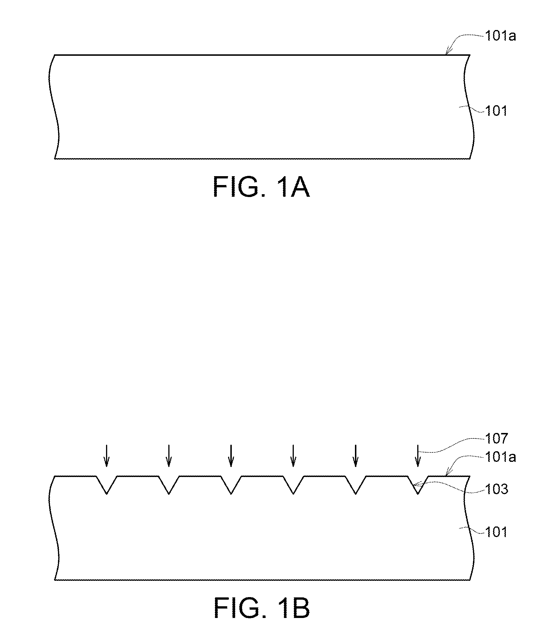
FIG. 1 is a flowchart of a method for fabricating a medical composite material 100 according to an embodiment of the present invention. FIG. 1A to FIG. 1D are structural cross-sectional views of the method for fabricating a medical composite material 100 of FIG. 1. Firstly, the method for fabricating the medical composite material 100 begins at step S1, a polymer layer 101 is provided (as indicated in FIG. 1A).
The polymer layer 101 can be formed of a polymer compound using a plasticized polymer such as plastic, silicone, synthetic rubber, synthetic fibers, synthetic paint or adhesive as the base, or a natural polymer compound comprising cellulose, starch, and protein.
In some embodiments of the present invention, the polymer layer 101 can be formed by performing injection molding, pultrusion, membrane pressing, thermal pressing, blow molding, molding, filament winding, prepreg material laminating, transferring, foaming, casting, or lamination on a thermoplastic plastic, such as polyethylene (PE), polypropylene (PP), polystyrene (PS), polymethyl methacrylate (PMMA), polyvinyl chloride (PVC), nylon (Nylon), polycarbonate (PC), polyurethane (PU), polytetrafluoroethylene (PTFE), polyethylene terephthalate (PET, PETE), or a thermosetting plastic, such as epoxy, phenolic, polyimide, melamine formaldehyde resin.
In the present embodiment, the polymer layer 101 is formed of a polymer comprising polyether ether ketone (PEEK), carbon reinforced (PEEK), polyetherketoneketone (PEKK), polyaryletherketone (PAEK) or a combination thereof. The properties of the polymer layer 101 are similar to that of human bones. For example, the polymer layer 101 has an elastic modulus substantially ranging from 2 Gpa to 22 Gpa.
It should be noted that the polymer layer 101 used in the present invention is not limited thereto, and any polymer materials suitable for contacting biological tissues are within the spirit of the present invention. In some embodiments, the polymer layer 101 can be formed of other polymer materials according to the biological properties of the biological tissue to which the medical composite material 100 is applied.
In step S2, a surface roughening process 107 is performed on a surface 101a of the polymer layer 101 to form a plurality of recesses 103 on the surface 101a, wherein each recess 103 has an aspect ratio substantially ranging from 1 .mu.m to 4000 .mu.m (as indicated in FIG. 1B). In some embodiments of the present invention, the surface roughening process 107 removes a part of the polymer layer 101 by way of CNC processing, laser surface treatment, plasma surface treatment, etching or a combination thereof to form a plurality of openings or grooves (recesses 103) extending into the polymer layer 101 from the surface 101a.
During the surface roughening process 107 of the present embodiment, a laser light with a pulse width less than 1 nanosecond (ns) is used to radiate the polymer layer 101, whereby a plurality of micro-structures having controllable and uniform dimensions are formed on the surface 101a of the polymer layer 101. The micro-structures are formed as an array pattern composed of a plurality of recesses 103 each having an aspect ratio ranging from 1 .mu.m to 4000 .mu.m. However, the arrangement of micro-structures is not limited thereto. For example, in some embodiments of the present invention, the micro-structures are an irregular pattern composed of a plurality of recesses 103 arranged in an irregular manner.
In step S3, an interface layer 102 is formed by the deposition process 104 to cover the surface 101a of the polymer layer 101 and fill the recesses 103. The interface layer 102 has a first surface 102a and a second surface 102b opposite to the first surface 102a. The first surface 102a is in contact with the polymer layer 101 and extends into the recesses 103 of the polymer layer 101, so as to form a plurality of protrusion portions 102c extending into the recesses 103 (as indicated in FIG. 1C). Since the interface layer 102 is conformally in contact with the polymer layer 101 and covers the surface 101a of the polymer layer 101, each protrusion portion 102c also has an aspect ratio substantially ranging from 1 .mu.m to 4000 .mu.m.
The shape and configurations of the protrusion portions 102c are arranged in corresponding to that of the recess 103. For example, the protrusion portions 102c can be arranged in a regular or an irregular manner according to the arrangement of the micro-structures on the surface 101a of the polymer layer 101. Each protrusion portion 102c can be shaped according to the shape of the opening of the corresponding recess 103. For example, the shape of the protrusion portion 102c can be an island structure, a tooth structure, a barb structure, a dove-shaped groove structure, a columnar structure or a combination thereof.
The deposition process 104 may comprise (but is not limited to) physical vapor deposition, chemical vapor deposition, electroplating, electroless plating, powder plasma spraying, laser powder deposition, casting, curing colloidal solution or a combination thereof. The interface layer 102 can be a single- or multi-layered structure. For example, in some embodiments of the present invention, the interface layer 102 comprises at least one layer of metal film formed of titanium (Ti), titanium alloy (Ti-6Al-4V), cobalt-chromium alloy (Co--Cr), stainless steel (SUS 316L), gold (Au), or a combination thereof.
The thickness of the interface layer 102 substantially ranges from 30 .mu.m to 500 .mu.m. In some embodiments of the present invention, the thickness of the interface layer 102, measured from the surface 101a of the polymer layer 101, is greater than 150 .mu.m. In the present embodiment, the interface layer 102 is formed by using a high power ion plating process (such as arc ion plating process) in conjunction with the synthetic powder granulation technology. A low temperature (such as 150.degree. C.) air plasma spray (APS) is performed using a titanium metal powder as a starting material to form at least one layer of titanium metal coating on the surface 101a of the polymer layer 101. In an exemplary embodiment of the present invention, at least one layer of titanium metal film having a thickness substantially greater than 1 .mu.m can be formed on the surface 101a of the polymer layer 101 by way of gradual plating.
Since the atoms of the titanium metal have smaller particles, the heat required for forming high ionized (>90%) particles with high energy (>20 eV) during the melting process can be reduced. Therefore, the surface temperature (<120.degree. C.) of the polymer layer 101 during the plating process can be reduced, the damage of the polymer layer 101 caused by impact of the melting powder colliding with the surface 101a of the polymer layer 101 can be reduced, and the adhesion between the interface layer 102 and the polymer layer 101 can be enhanced.
Moreover, the interface layer 102 can act as a thermal dissipation layer and a buffer layer to avoid the heat generated by the subsequent processes from being accumulated on the surface 101a of the polymer layer 101. When the thickness of the interface layer 102 reaches a certain level, such as greater than 150 .mu.m, the temperature on the surface 101a of the polymer layer 101 can be reduced under the melting point during the subsequent processes, so as to avoid the thermal stress concentrated in subsequent process from penetrating and damaging the polymer layer 101. Besides, since the titanium metal film is conformally in contact with and fills the recesses 103 of the polymer layer 101, thus the plurality of protrusion portions 102c formed in the recesses 103 can have controllable and uniform dimensions to uniformly reduce the residual stress applied on the polymer layer 101 via the interface layer 102 and to avoid the interface layer 102 and the polymer layer 101 from being peeled off by an external force.
In step S4, a surface plating process is performed on the second surface 102b of the interface layer 102 to form a metal layer 106 (as indicated in FIG. 1D) and complete the preparation of the medical composite material 100. In an exemplary embodiment of the present invention, the surface plating process can be a metal melting process, comprises: guiding an energy beam 105 (comprising the power sources, such as laser beam, electron beam, arc, plasma, electromagnetic conduction or the combination thereof) to smelt metal powder by way of sintering, melting and solidification or a combination thereof, so as to form a porous array metal structure on the second surface 102b of the interface layer 102. The interface layer has a thickness substantially ranging from 30 .mu.m to 500 .mu.m. The metal powder may comprise titanium, gold, silver, iron or a combination thereof. The sintering process can be a selective laser sintering (SLS) process or a direct metal laser sintering (DMLS) process. The melting process can be a selective laser melting (SLM) process or an electron beam melting (EBM) process.
In an exemplary embodiment of the present invention, the porous array metal structure of the metal layer 106 can be a metal mesh structure 206 as shown in FIG. 2. Although the metal mesh structure 206 depicted in FIG. 2 is illustrated as a multi-layered structure in the present embodiment, the metal mesh structure 206 can be a single-layered structure in other embodiments. Since the metal layer 106 has superior biocompatibility for inducing tissue cells to grow on the metal mesh structure 206, thus the metal layer 106 can be tightly fused with the tissues in which it is implanted.
Exemplarily but not restrictively, the medical composite material 100 fabricated by the above method can be used in such as bone screws, spinal fixation device, inter-body fusion device, artificial disk and artificial joints. Refer to FIG. 3A and FIG. 3B. FIG. 3A is a 3D structural perspective of an inter-body fusion device using the medical composite material 100 according to an embodiment of the present invention. FIG. 3B is a structural explosion diagram of the inter-body fusion device 300 of FIG. 3A. The inter-body fusion device 300 comprises a body 301, a first interface layer 302, a second interface layer 303, a first osseo-integration layer 304 and a second osseo-integration layer 305.
The body 301 at least comprises the medical composite material 100 which constitutes the polymer layer 101. For example, in some embodiments of the present invention, the body can be a bulk formed of a material identical to that for forming the polymer layer 101. In some embodiments of the present invention, the body 301 can be a carrying substrate formed of other materials, and the polymer layer 101 is fixed on the top surface and the bottom surface of the carrying substrate (not illustrated) by way of attachment, latching, thermal pressing, or assembly using fasteners, slide slots, bolts, and screw locks. In the present embodiment, the body 301 is a bulk formed of a polymer comprising polyether ether ketone (PEEK), and has an elastic modulus similar to human bone tissues. Thus when the medical composite material 100 is applied to human bone tissues the problems derived from stress shielding effect can be avoided.
The first interface layer 302 and the second interface layer 303, respectively formed on the surfaces 301a and 301b of the body 301 serving as the interface layer 102 of FIG. 1D, are tightly bonded to the body 301, and act as a thermal dissipation layer and a buffer layer to avoid the polymer layer 101 of the body 301 from being damaged by the thermal stress generated by the subsequent processes. In the present embodiment, the structure, materials and formation method of the first interface layer 302 and the second interface layer 303 are exactly the same as that of the interface layer 102 of the medical composite material 100, and the similarities are not redundantly repeated here.
The first osseo-integration layer 304 and the second osseo-integration layer 305 are respectively formed outside the first interface layer 302 and the second interface layer 303, whereby the first interface layer 302 is disposed between body 301 and the first osseo-integration layer 304, and the second interface layer 303 is disposed between the body 301 and the second osseo-integration layer 305. In the present embodiment, since the structures, materials and formation method of the first osseo-integration layer 304 and the second osseo-integration layer 304 are exactly the same as that of the metal layer 106 of the medical composite material 100, thus the first osseo-integration layer 304 and the second osseo-integration layer 305 can be directly sintered (melted) and cured on the first interface layer 302 and the second interface layer 303 to form a one-piece structure with the body 301.
Referring to FIG. 4, a structural diagram of the inter-body fusion device 300 of FIG. 3 used in human vertebrae 400 according to an embodiment of the present invention is shown. The intervertebral disc 300 is implanted between two adjacent vertebrae 400. In some embodiments of the present invention, the inter-body fusion device 300 further comprises a plurality of occlusal teeth 306 disposed on a surface of the first osseo-integration layer 304 and the second osseo-integration layer 305 away from the first interface layer 302 and the second interface layer 303 for improving the security of the inter-body fusion device 300 implanted between the two adjacent vertebrae 400.
In addition, a porous structure, a gradient porous structure, an inducing growth structure, a bionic structure, a physical structure, an increasing friction coefficient structure, a anti-wear structure, a gradient characteristic structure or a combination thereof (not illustrated) suitable for blood and cells attached thereon can be formed on the surface of the occlusal teeth 306 by a surface treatment technology to prompt the fusion between the artificial intervertebral disc 300 and the vertebra.
In accordance with the above disclosure, the embodiments of the present invention disclose a medical composite material with hetero-junction, a method for fabricating the same and applications thereof are disclosed. Firstly, an interface layer 102 is formed on the polymer layer 101 for contacting the polymer layer 101, wherein the interface layer 102 has a plurality of protrusion portions extending into the polymer layer and each protrusion portion has an aspect ratio substantially ranging from 1 .mu.m to 4000 .mu.m. Then, a metal layer with a porous array metal structure is sintered (melted) and cured on the interface layer.
Since the interface layer 102 can be formed on the polymer layer 101 by a low temperature plating technology to avoid the thermal stress concentrated in the subsequent processes from penetrating and damaging the polymer layer 101, thus heterogeneous materials, such as a metal layer and a polymer layer, can be bonded together, and the medical composite material 100, which approximates the nature of human tissues and has excellent developable properties and biocompatibility, can be fabricated.
The medical composite material 100 can be used in the inter-body fusion device 300 for inducing bone cells to grow, such that the inter-body fusion device 300 can be integrated with adjacent vertebrae 400 without peeling off. Moreover, since the polymer material and the adjacent vertebrae has similar elastic modulus, thus stress shielding effect occurs on the prior art medical material that is formed of one single material can be avoided. As a result, the problems encountered in generally known technology can be resolved.
It will be apparent to those skilled in the art that various modifications and variations can be made to the disclosed embodiments. It is intended that the specification and examples be considered as exemplary only, with a true scope of the disclosure being indicated by the following claims and their equivalents
* * * * *
References
D00000
D00001
D00002
D00003
D00004
D00005
D00006
XML
uspto.report is an independent third-party trademark research tool that is not affiliated, endorsed, or sponsored by the United States Patent and Trademark Office (USPTO) or any other governmental organization. The information provided by uspto.report is based on publicly available data at the time of writing and is intended for informational purposes only.
While we strive to provide accurate and up-to-date information, we do not guarantee the accuracy, completeness, reliability, or suitability of the information displayed on this site. The use of this site is at your own risk. Any reliance you place on such information is therefore strictly at your own risk.
All official trademark data, including owner information, should be verified by visiting the official USPTO website at www.uspto.gov. This site is not intended to replace professional legal advice and should not be used as a substitute for consulting with a legal professional who is knowledgeable about trademark law.