Calibration error conditions
Lehnert , et al. Oc
U.S. patent number 10,462,592 [Application Number 16/185,906] was granted by the patent office on 2019-10-29 for calibration error conditions. This patent grant is currently assigned to Sonos, Inc.. The grantee listed for this patent is Sonos, Inc.. Invention is credited to Hilmar Lehnert, Timothy Sheen, Dayn Wilberding.


| United States Patent | 10,462,592 |
| Lehnert , et al. | October 29, 2019 |
Calibration error conditions
Abstract
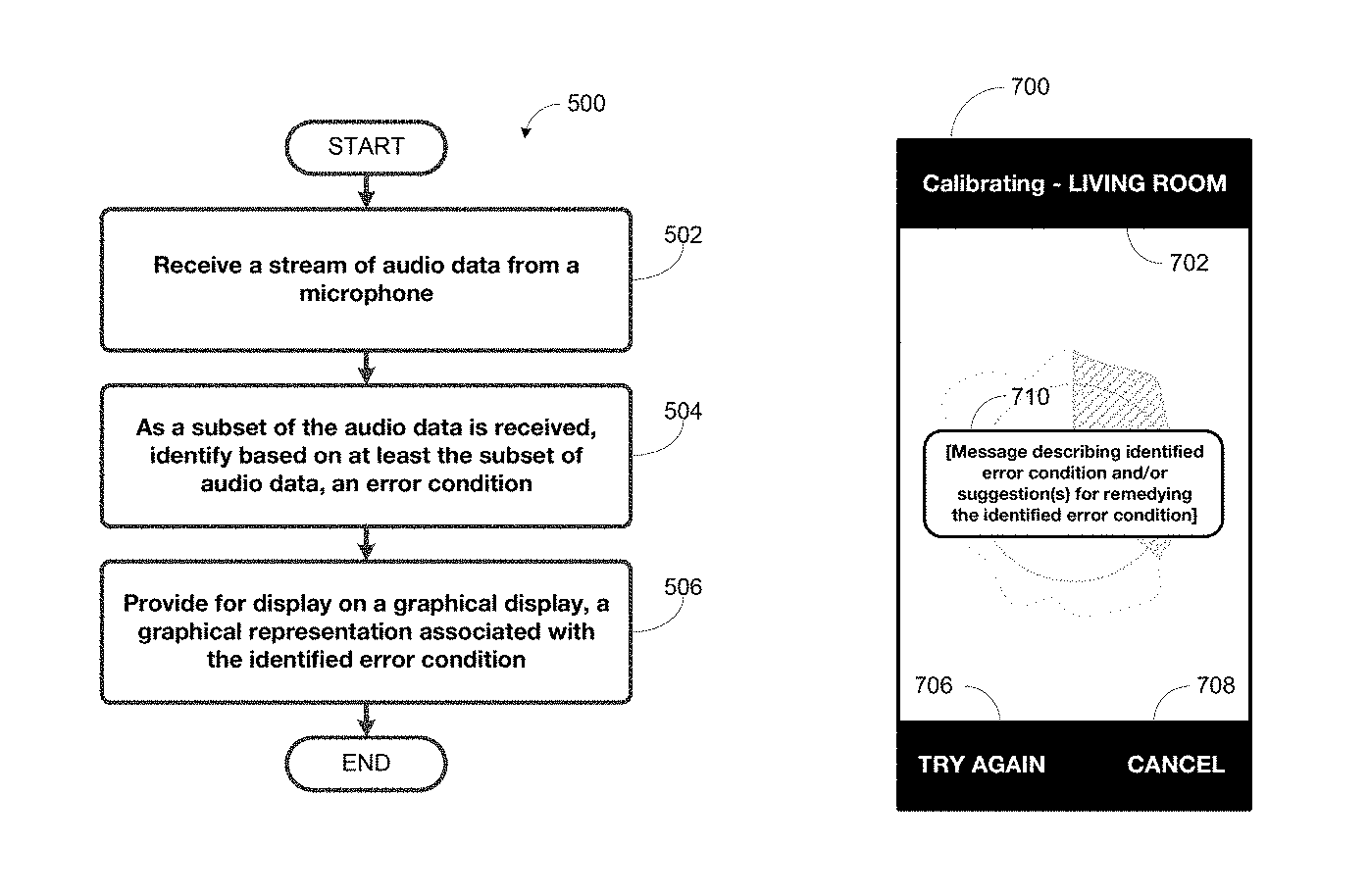
Examples described herein involve identifying one or more error conditions during calibration of one or more playback devices in a playback environment. A microphone of a network device may detect and sample an audio signal while the one or more playback devices in the playback environment plays a calibration tone. A processor of the network device may then receive, from the microphone, a stream of audio data. The audio data may include an audio signal component and a background noise component. As a subset of the audio data is received, the processor may identify based on the audio data, the one or more error conditions. The processor may then cause a graphical display to display a graphical representation associated with the identified error condition.
| Inventors: | Lehnert; Hilmar (Framingham, MA), Sheen; Timothy (Brighton, MA), Wilberding; Dayn (Santa Barbara, CA) | ||||||||||
|---|---|---|---|---|---|---|---|---|---|---|---|
| Applicant: |
|
||||||||||
| Assignee: | Sonos, Inc. (Santa Barbara,
CA) |
||||||||||
| Family ID: | 55068570 | ||||||||||
| Appl. No.: | 16/185,906 | ||||||||||
| Filed: | November 9, 2018 |
Prior Publication Data
| Document Identifier | Publication Date | |
|---|---|---|
| US 20190082280 A1 | Mar 14, 2019 | |
Related U.S. Patent Documents
| Application Number | Filing Date | Patent Number | Issue Date | ||
|---|---|---|---|---|---|
| 15718556 | Sep 28, 2017 | 10129679 | |||
| 15344069 | Oct 3, 2017 | 9781533 | |||
| 14811587 | Jan 30, 2017 | 9538305 | |||
| Current U.S. Class: | 1/1 |
| Current CPC Class: | H04R 29/008 (20130101); G06F 3/165 (20130101); H04R 27/00 (20130101); H04S 7/301 (20130101); H04R 2227/005 (20130101); H04S 7/303 (20130101); H04R 29/00 (20130101); H04S 7/302 (20130101); H04R 29/001 (20130101) |
| Current International Class: | H04S 7/00 (20060101); H04R 29/00 (20060101); H04R 27/00 (20060101); G06F 3/16 (20060101) |
| Field of Search: | ;381/58-59,55 |
References Cited [Referenced By]
U.S. Patent Documents
| 679889 | August 1901 | Charles |
| 4306113 | December 1981 | Morton |
| 4342104 | July 1982 | Jack |
| 4504704 | March 1985 | Ohyaba et al. |
| 4592088 | May 1986 | Shimada |
| 4628530 | December 1986 | Op et al. |
| 4631749 | December 1986 | Rapaich |
| 4694484 | September 1987 | Atkinson et al. |
| 4773094 | September 1988 | Dolby |
| 4995778 | February 1991 | Bruessel |
| 5218710 | June 1993 | Yamaki et al. |
| 5255326 | October 1993 | Stevenson |
| 5323257 | June 1994 | Abe et al. |
| 5386478 | January 1995 | Plunkett |
| 5440644 | August 1995 | Farinelli et al. |
| 5553147 | September 1996 | Pineau |
| 5581621 | December 1996 | Koyama et al. |
| 5757927 | May 1998 | Gerzon et al. |
| 5761320 | June 1998 | Farinelli et al. |
| 5910991 | June 1999 | Farrar |
| 5923902 | July 1999 | Inagaki |
| 5939656 | August 1999 | Suda |
| 6018376 | January 2000 | Nakatani |
| 6032202 | February 2000 | Lea et al. |
| 6072879 | June 2000 | Ouchi et al. |
| 6111957 | August 2000 | Thomasson |
| 6256554 | July 2001 | DiLorenzo |
| 6363155 | March 2002 | Horbach |
| 6404811 | June 2002 | Cvetko et al. |
| 6469633 | October 2002 | Wachter et al. |
| 6522886 | February 2003 | Youngs et al. |
| 6573067 | June 2003 | Dib-Hajj et al. |
| 6611537 | August 2003 | Edens et al. |
| 6631410 | October 2003 | Kowalski et al. |
| 6639989 | October 2003 | Zacharov et al. |
| 6643744 | November 2003 | Cheng |
| 6704421 | March 2004 | Kitamura |
| 6721428 | April 2004 | Allred et al. |
| 6757517 | June 2004 | Chang et al. |
| 6760451 | July 2004 | Craven et al. |
| 6766025 | July 2004 | Levy et al. |
| 6778869 | August 2004 | Champion |
| 6798889 | September 2004 | Dicker et al. |
| 6862440 | March 2005 | Sampath |
| 6916980 | July 2005 | Ishida et al. |
| 6931134 | August 2005 | Waller, Jr. et al. |
| 6985694 | January 2006 | De Bonet et al. |
| 6990211 | January 2006 | Parker |
| 7039212 | May 2006 | Poling et al. |
| 7058186 | June 2006 | Tanaka |
| 7072477 | July 2006 | Kincaid |
| 7103187 | September 2006 | Neuman |
| 7130608 | October 2006 | Hollstrom et al. |
| 7130616 | October 2006 | Janik |
| 7143939 | December 2006 | Henzerling |
| 7187947 | March 2007 | White et al. |
| 7236773 | June 2007 | Thomas |
| 7289637 | October 2007 | Montag et al. |
| 7295548 | November 2007 | Blank et al. |
| 7312785 | December 2007 | Tsuk et al. |
| 7391791 | June 2008 | Balassanian et al. |
| 7477751 | January 2009 | Lyon et al. |
| 7483538 | January 2009 | McCarty et al. |
| 7483540 | January 2009 | Rabinowitz et al. |
| 7489784 | February 2009 | Yoshino |
| 7490044 | February 2009 | Kulkarni |
| 7492909 | February 2009 | Carter et al. |
| 7519188 | April 2009 | Berardi et al. |
| 7529377 | May 2009 | Nackvi et al. |
| 7571014 | August 2009 | Lambourne et al. |
| 7590772 | September 2009 | Marriott et al. |
| 7630500 | December 2009 | Beckman et al. |
| 7630501 | December 2009 | Blank et al. |
| 7643894 | January 2010 | Braithwaite et al. |
| 7657910 | February 2010 | McAulay et al. |
| 7664276 | February 2010 | McKee |
| 7676044 | March 2010 | Sasaki et al. |
| 7689305 | March 2010 | Kreifeldt et al. |
| 7720237 | May 2010 | Bharitkar et al. |
| 7742740 | June 2010 | Goldberg et al. |
| 7769183 | August 2010 | Bharitkar et al. |
| 7796068 | September 2010 | Raz et al. |
| 7835689 | November 2010 | Goldberg et al. |
| 7853341 | December 2010 | McCarty et al. |
| 7876903 | January 2011 | Sauk |
| 7925203 | April 2011 | Lane et al. |
| 7949140 | May 2011 | Kino |
| 7949707 | May 2011 | McDowall et al. |
| 7961893 | June 2011 | Kino |
| 7970922 | June 2011 | Svendsen |
| 7987294 | July 2011 | Bryce et al. |
| 8005228 | August 2011 | Bharitkar et al. |
| 8014423 | September 2011 | Thaler et al. |
| 8045721 | October 2011 | Burgan et al. |
| 8045952 | October 2011 | Qureshey et al. |
| 8050652 | November 2011 | Qureshey et al. |
| 8063698 | November 2011 | Howard |
| 8074253 | December 2011 | Nathan |
| 8103009 | January 2012 | McCarty et al. |
| 8116476 | February 2012 | Inohara |
| 8126172 | February 2012 | Horbach et al. |
| 8131390 | March 2012 | Braithwaite et al. |
| 8139774 | March 2012 | Berardi et al. |
| 8144883 | March 2012 | Pdersen et al. |
| 8160276 | April 2012 | Liao et al. |
| 8160281 | April 2012 | Kim et al. |
| 8170260 | May 2012 | Reining et al. |
| 8175292 | May 2012 | Aylward et al. |
| 8175297 | May 2012 | Ho et al. |
| 8194874 | June 2012 | Starobin et al. |
| 8229125 | July 2012 | Short |
| 8233632 | July 2012 | MacDonald et al. |
| 8234395 | July 2012 | Millington et al. |
| 8238547 | August 2012 | Ohki et al. |
| 8238578 | August 2012 | Aylward |
| 8243961 | August 2012 | Morrill |
| 8264408 | September 2012 | Kainulainen et al. |
| 8265310 | September 2012 | Berardi et al. |
| 8270620 | September 2012 | Christensen et al. |
| 8279709 | October 2012 | Choisel et al. |
| 8281001 | October 2012 | Busam et al. |
| 8290185 | October 2012 | Kim |
| 8291349 | October 2012 | Park et al. |
| 8300845 | October 2012 | Zurek et al. |
| 8306235 | November 2012 | Mahowald |
| 8325931 | December 2012 | Howard et al. |
| 8325935 | December 2012 | Rutschman |
| 8331585 | December 2012 | Hagen et al. |
| 8332414 | December 2012 | Nguyen et al. |
| 8379876 | February 2013 | Zhang |
| 8391501 | March 2013 | Khawand et al. |
| 8392505 | March 2013 | Haughay et al. |
| 8401202 | March 2013 | Brooking |
| 8433076 | April 2013 | Zurek et al. |
| 8452020 | May 2013 | Gregg et al. |
| 8463184 | June 2013 | Dua |
| 8483853 | July 2013 | Lambourne et al. |
| 8488799 | July 2013 | Goldstein et al. |
| 8503669 | August 2013 | Mao |
| 8527876 | September 2013 | Wood et al. |
| 8577045 | November 2013 | Gibbs |
| 8577048 | November 2013 | Chaikin et al. |
| 8600075 | December 2013 | Lim |
| 8620006 | December 2013 | Berardi et al. |
| 8731206 | May 2014 | Park |
| 8755538 | June 2014 | Kwon |
| 8798280 | August 2014 | Goldberg et al. |
| 8819554 | August 2014 | Basso et al. |
| 8831244 | September 2014 | Apfel |
| 8855319 | October 2014 | Liu et al. |
| 8862273 | October 2014 | Karr |
| 8879761 | November 2014 | Johnson et al. |
| 8903526 | December 2014 | Beckhardt et al. |
| 8914559 | December 2014 | Kalayjian et al. |
| 8930005 | January 2015 | Reimann et al. |
| 8934647 | January 2015 | Joyce et al. |
| 8934655 | January 2015 | Breen et al. |
| 8942252 | January 2015 | Balassanian et al. |
| 8965033 | February 2015 | Wiggins |
| 8965546 | February 2015 | Visser et al. |
| 8977974 | March 2015 | Kraut |
| 8984442 | March 2015 | Pirnack et al. |
| 8989406 | March 2015 | Wong et al. |
| 8995687 | March 2015 | Marino, Jr. et al. |
| 8996370 | March 2015 | Ansell |
| 9020153 | April 2015 | Britt, Jr. |
| 9021153 | April 2015 | Lu |
| 9065929 | June 2015 | Chen et al. |
| 9084058 | July 2015 | Reilly et al. |
| 9100766 | August 2015 | Soulodre et al. |
| 9106192 | August 2015 | Sheen et al. |
| 9179233 | November 2015 | Kang |
| 9215545 | December 2015 | Dublin et al. |
| 9219460 | December 2015 | Bush |
| 9231545 | January 2016 | Agustin et al. |
| 9286384 | March 2016 | Kuper et al. |
| 9288597 | March 2016 | Carlsson et al. |
| 9300266 | March 2016 | Grokop |
| 9319816 | April 2016 | Narayanan |
| 9451377 | September 2016 | Massey |
| 9462399 | October 2016 | Bharitkar et al. |
| 9467779 | October 2016 | Iyengar et al. |
| 9472201 | October 2016 | Sleator |
| 9489948 | November 2016 | Chu et al. |
| 9524098 | December 2016 | Griffiths et al. |
| 9538305 | January 2017 | Lehnert et al. |
| 9538308 | January 2017 | Isaac et al. |
| 9560449 | January 2017 | Carlsson et al. |
| 9560460 | January 2017 | Chaikin et al. |
| 9609383 | March 2017 | Hirst |
| 9615171 | April 2017 | O'Neill et al. |
| 9674625 | June 2017 | Armstrong-Muntner et al. |
| 9689960 | June 2017 | Barton et al. |
| 9690271 | June 2017 | Sheen et al. |
| 9706323 | July 2017 | Sheen et al. |
| 9723420 | August 2017 | Family et al. |
| 9743207 | August 2017 | Hartung |
| 9743208 | August 2017 | Oishi et al. |
| 9763018 | September 2017 | McPherson et al. |
| 9788113 | October 2017 | Wilberding et al. |
| 9860662 | January 2018 | Jarvis et al. |
| 9864574 | January 2018 | Hartung et al. |
| 10045142 | August 2018 | McPherson et al. |
| 10206052 | February 2019 | Perianu |
| 2001/0038702 | November 2001 | Lavoie et al. |
| 2001/0042107 | November 2001 | Palm |
| 2001/0043592 | November 2001 | Jimenez et al. |
| 2002/0022453 | February 2002 | Balog et al. |
| 2002/0026442 | February 2002 | Lipscomb et al. |
| 2002/0078161 | June 2002 | Cheng |
| 2002/0089529 | July 2002 | Robbin |
| 2002/0124097 | September 2002 | Isely et al. |
| 2002/0126852 | September 2002 | Kashani et al. |
| 2002/0136414 | September 2002 | Jordan et al. |
| 2002/0146136 | October 2002 | Carter et al. |
| 2003/0002689 | January 2003 | Folio |
| 2003/0031334 | February 2003 | Layton et al. |
| 2003/0157951 | August 2003 | Hasty |
| 2003/0161479 | August 2003 | Yang et al. |
| 2003/0161492 | August 2003 | Miller et al. |
| 2003/0179891 | September 2003 | Rabinowitz et al. |
| 2003/0235311 | December 2003 | Grancea et al. |
| 2004/0024478 | February 2004 | Hans et al. |
| 2004/0131338 | July 2004 | Asada et al. |
| 2004/0237750 | December 2004 | Smith et al. |
| 2005/0031143 | February 2005 | Devantier et al. |
| 2005/0063554 | March 2005 | Devantier et al. |
| 2005/0147261 | July 2005 | Yeh |
| 2005/0157885 | July 2005 | Olney et al. |
| 2006/0008256 | January 2006 | Khedouri et al. |
| 2006/0026521 | February 2006 | Hotelling et al. |
| 2006/0032357 | February 2006 | Roovers et al. |
| 2006/0195480 | August 2006 | Spiegelman et al. |
| 2006/0225097 | October 2006 | Lawrence-Apfelbaum |
| 2007/0003067 | January 2007 | Gierl et al. |
| 2007/0025559 | February 2007 | Mihelich et al. |
| 2007/0032895 | February 2007 | Nackvi et al. |
| 2007/0038999 | February 2007 | Millington et al. |
| 2007/0086597 | April 2007 | Kino |
| 2007/0116254 | May 2007 | Looney et al. |
| 2007/0121955 | May 2007 | Johnston et al. |
| 2007/0142944 | June 2007 | Goldberg et al. |
| 2008/0002839 | January 2008 | Eng |
| 2008/0065247 | March 2008 | Igoe et al. |
| 2008/0069378 | March 2008 | Rabinowitz et al. |
| 2008/0077261 | March 2008 | Baudino et al. |
| 2008/0098027 | April 2008 | Aarts |
| 2008/0136623 | June 2008 | Calvarese |
| 2008/0144864 | June 2008 | Huon et al. |
| 2008/0175411 | July 2008 | Greve |
| 2008/0232603 | September 2008 | Soulodre et al. |
| 2008/0266385 | October 2008 | Smith et al. |
| 2008/0281523 | November 2008 | Dahl et al. |
| 2009/0003613 | January 2009 | Christensen et al. |
| 2009/0024662 | January 2009 | Park et al. |
| 2009/0047993 | February 2009 | Vasa |
| 2009/0063274 | March 2009 | Dublin, III et al. |
| 2009/0110218 | April 2009 | Swain |
| 2009/0138507 | May 2009 | Burckart et al. |
| 2009/0147134 | June 2009 | Iwamatsu |
| 2009/0180632 | July 2009 | Goldberg et al. |
| 2009/0196428 | August 2009 | Kim |
| 2009/0202082 | August 2009 | Bharitkar et al. |
| 2009/0252481 | October 2009 | Ekstrand |
| 2009/0304194 | December 2009 | Eggleston |
| 2009/0304205 | December 2009 | Hardacker et al. |
| 2009/0316923 | December 2009 | Tashev et al. |
| 2010/0095332 | April 2010 | Gran et al. |
| 2010/0128902 | May 2010 | Liu et al. |
| 2010/0135501 | June 2010 | Corbett et al. |
| 2010/0142735 | June 2010 | Yoon |
| 2010/0146445 | June 2010 | Kraut |
| 2010/0162117 | June 2010 | Basso et al. |
| 2010/0189203 | July 2010 | Wilhelmsson et al. |
| 2010/0195846 | August 2010 | Yokoyama |
| 2010/0272270 | October 2010 | Chaikin et al. |
| 2010/0296659 | November 2010 | Tanaka |
| 2010/0303248 | December 2010 | Tawada |
| 2010/0303250 | December 2010 | Goldberg et al. |
| 2010/0323793 | December 2010 | Andall et al. |
| 2011/0007904 | January 2011 | Tomoda et al. |
| 2011/0007905 | January 2011 | Sato et al. |
| 2011/0087842 | April 2011 | Lu et al. |
| 2011/0091055 | April 2011 | Leblanc |
| 2011/0135103 | June 2011 | Sun et al. |
| 2011/0170710 | July 2011 | Son |
| 2011/0234480 | September 2011 | Fino et al. |
| 2011/0235808 | September 2011 | Kon |
| 2011/0268281 | November 2011 | Florencio et al. |
| 2012/0032928 | February 2012 | Alberth et al. |
| 2012/0051558 | March 2012 | Kim et al. |
| 2012/0057724 | March 2012 | Rabinowitz et al. |
| 2012/0093320 | April 2012 | Flaks et al. |
| 2012/0127831 | May 2012 | Gicklhorn et al. |
| 2012/0140936 | June 2012 | Bonnick et al. |
| 2012/0148075 | June 2012 | Goh et al. |
| 2012/0183156 | July 2012 | Schlessinger et al. |
| 2012/0213391 | August 2012 | Usami et al. |
| 2012/0215530 | August 2012 | Harsch et al. |
| 2012/0237037 | September 2012 | Ninan et al. |
| 2012/0243697 | September 2012 | Frye et al. |
| 2012/0263325 | October 2012 | Freeman et al. |
| 2012/0268145 | October 2012 | Chandra et al. |
| 2012/0269356 | October 2012 | Sheerin et al. |
| 2012/0275613 | November 2012 | Soulodre et al. |
| 2012/0283593 | November 2012 | Searchfield et al. |
| 2012/0288124 | November 2012 | Fejzo et al. |
| 2013/0010970 | January 2013 | Hegarty et al. |
| 2013/0028443 | January 2013 | Pance et al. |
| 2013/0051572 | February 2013 | Goh et al. |
| 2013/0066453 | March 2013 | Seefeldt et al. |
| 2013/0108055 | May 2013 | Hanna et al. |
| 2013/0129102 | May 2013 | Li et al. |
| 2013/0129122 | May 2013 | Johnson et al. |
| 2013/0202131 | August 2013 | Kemmochi et al. |
| 2013/0211843 | August 2013 | Clarkson |
| 2013/0216071 | August 2013 | Maher et al. |
| 2013/0223642 | August 2013 | Warren et al. |
| 2013/0230175 | September 2013 | Bech et al. |
| 2013/0259254 | October 2013 | Xiang et al. |
| 2013/0279706 | October 2013 | Marti et al. |
| 2013/0305152 | November 2013 | Griffiths et al. |
| 2013/0315405 | November 2013 | Kanishima et al. |
| 2013/0329896 | December 2013 | Krishnaswamy et al. |
| 2013/0331970 | December 2013 | Beckhardt et al. |
| 2014/0003622 | January 2014 | Ikizyan et al. |
| 2014/0003623 | January 2014 | Lang |
| 2014/0003625 | January 2014 | Sheen et al. |
| 2014/0003626 | January 2014 | Holman et al. |
| 2014/0003635 | January 2014 | Mohammad et al. |
| 2014/0006587 | January 2014 | Kusano et al. |
| 2014/0016784 | January 2014 | Sen et al. |
| 2014/0016786 | January 2014 | Sen |
| 2014/0016802 | January 2014 | Sen |
| 2014/0023196 | January 2014 | Xiang et al. |
| 2014/0029201 | January 2014 | Yang et al. |
| 2014/0037097 | February 2014 | Labosco |
| 2014/0037107 | February 2014 | Marino, Jr. et al. |
| 2014/0052770 | February 2014 | Gran et al. |
| 2014/0064501 | March 2014 | Olsen et al. |
| 2014/0079242 | March 2014 | Nguyen et al. |
| 2014/0084014 | March 2014 | Sim et al. |
| 2014/0086423 | March 2014 | Domingo et al. |
| 2014/0112481 | April 2014 | Li et al. |
| 2014/0119551 | May 2014 | Bharitkar et al. |
| 2014/0126730 | May 2014 | Crawley et al. |
| 2014/0161265 | June 2014 | Chaikin et al. |
| 2014/0169569 | June 2014 | Toivanen et al. |
| 2014/0180684 | June 2014 | Strub |
| 2014/0192986 | July 2014 | Lee et al. |
| 2014/0219456 | August 2014 | Morrell et al. |
| 2014/0219483 | August 2014 | Hong |
| 2014/0226823 | August 2014 | Sen et al. |
| 2014/0242913 | August 2014 | Pang |
| 2014/0267148 | September 2014 | Luna et al. |
| 2014/0270202 | September 2014 | Ivanov et al. |
| 2014/0270282 | September 2014 | Tammi et al. |
| 2014/0273859 | September 2014 | Luna et al. |
| 2014/0279889 | September 2014 | Luna et al. |
| 2014/0285313 | September 2014 | Luna et al. |
| 2014/0286496 | September 2014 | Luna et al. |
| 2014/0294200 | October 2014 | Baumgarte et al. |
| 2014/0294201 | October 2014 | Johnson et al. |
| 2014/0310269 | October 2014 | Zhang et al. |
| 2014/0321670 | October 2014 | Nystrom et al. |
| 2014/0323036 | October 2014 | Daley et al. |
| 2014/0334644 | November 2014 | Selig et al. |
| 2014/0341399 | November 2014 | Dusse |
| 2014/0344689 | November 2014 | Scott et al. |
| 2014/0355768 | December 2014 | Sen et al. |
| 2014/0355794 | December 2014 | Morrell et al. |
| 2015/0011195 | January 2015 | Li |
| 2015/0016642 | January 2015 | Walsh et al. |
| 2015/0023509 | January 2015 | Devantier et al. |
| 2015/0031287 | January 2015 | Pang et al. |
| 2015/0032844 | January 2015 | Tarr et al. |
| 2015/0036847 | February 2015 | Donaldson |
| 2015/0036848 | February 2015 | Donaldson |
| 2015/0043736 | February 2015 | Olsen et al. |
| 2015/0063610 | March 2015 | Mossner |
| 2015/0078586 | March 2015 | Ang et al. |
| 2015/0078596 | March 2015 | Sprogis et al. |
| 2015/0100991 | April 2015 | Risberg et al. |
| 2015/0146886 | May 2015 | Baumgarte |
| 2015/0149943 | May 2015 | Nguyen et al. |
| 2015/0161360 | June 2015 | Paruchuri et al. |
| 2015/0195666 | July 2015 | Massey et al. |
| 2015/0201274 | July 2015 | Ellner et al. |
| 2015/0208184 | July 2015 | Tan et al. |
| 2015/0212788 | July 2015 | Lang |
| 2015/0220558 | August 2015 | Snibbe et al. |
| 2015/0223002 | August 2015 | Mehta et al. |
| 2015/0229699 | August 2015 | Liu |
| 2015/0260754 | September 2015 | Perotti et al. |
| 2015/0271616 | September 2015 | Kechichian et al. |
| 2015/0281866 | October 2015 | Williams et al. |
| 2015/0289064 | October 2015 | Jensen et al. |
| 2015/0358756 | December 2015 | Harma et al. |
| 2015/0382128 | December 2015 | Ridihalgh |
| 2016/0007116 | January 2016 | Holman |
| 2016/0011846 | January 2016 | Sheen |
| 2016/0011850 | January 2016 | Sheen et al. |
| 2016/0014509 | January 2016 | Hansson et al. |
| 2016/0014510 | January 2016 | Sheen et al. |
| 2016/0014511 | January 2016 | Sheen et al. |
| 2016/0014534 | January 2016 | Sheen et al. |
| 2016/0014536 | January 2016 | Sheen |
| 2016/0021458 | January 2016 | Johnson et al. |
| 2016/0021473 | January 2016 | Riggi et al. |
| 2016/0021481 | January 2016 | Johnson et al. |
| 2016/0027467 | January 2016 | Proud |
| 2016/0029142 | January 2016 | Isaac et al. |
| 2016/0035337 | February 2016 | Aggarwal et al. |
| 2016/0036881 | February 2016 | Tembey et al. |
| 2016/0037277 | February 2016 | Matsumoto et al. |
| 2016/0061597 | March 2016 | De et al. |
| 2016/0070526 | March 2016 | Sheen |
| 2016/0073210 | March 2016 | Sheen et al. |
| 2016/0140969 | May 2016 | Srinivasan et al. |
| 2016/0165297 | June 2016 | Jamal-Syed et al. |
| 2016/0192098 | June 2016 | Oishi et al. |
| 2016/0192099 | June 2016 | Oishi et al. |
| 2016/0212535 | July 2016 | Le et al. |
| 2016/0239255 | August 2016 | Chavez et al. |
| 2016/0260140 | September 2016 | Shirley et al. |
| 2016/0309276 | October 2016 | Ridihalgh et al. |
| 2016/0313971 | October 2016 | Bierbower et al. |
| 2016/0316305 | October 2016 | Sheen et al. |
| 2016/0330562 | November 2016 | Crockett |
| 2016/0366517 | December 2016 | Chandran et al. |
| 2017/0069338 | March 2017 | Elliot et al. |
| 2017/0083279 | March 2017 | Sheen et al. |
| 2017/0086003 | March 2017 | Rabinowitz et al. |
| 2017/0105084 | April 2017 | Holman |
| 2017/0142532 | May 2017 | Pan |
| 2017/0207762 | July 2017 | Porter et al. |
| 2017/0223447 | August 2017 | Johnson et al. |
| 2017/0230772 | August 2017 | Johnson et al. |
| 2017/0257722 | September 2017 | Kerdranvat et al. |
| 2017/0280265 | September 2017 | Po |
| 2017/0303039 | October 2017 | Iyer et al. |
| 2017/0311108 | October 2017 | Patel et al. |
| 2017/0374482 | December 2017 | McPherson et al. |
| 2019/0037328 | January 2019 | McPherson et al. |
| 1447624 | Oct 2003 | CN | |||
| 101366177 | Feb 2009 | CN | |||
| 101491116 | Jul 2009 | CN | |||
| 102318325 | Jan 2012 | CN | |||
| 102893633 | Jan 2013 | CN | |||
| 103988523 | Aug 2014 | CN | |||
| 0505949 | Sep 1992 | EP | |||
| 0772374 | May 1997 | EP | |||
| 1133896 | Aug 2002 | EP | |||
| 1349427 | Oct 2003 | EP | |||
| 1389853 | Feb 2004 | EP | |||
| 2043381 | Apr 2009 | EP | |||
| 1349427 | Dec 2009 | EP | |||
| 2161950 | Mar 2010 | EP | |||
| 2194471 | Jun 2010 | EP | |||
| 2197220 | Jun 2010 | EP | |||
| 2429155 | Mar 2012 | EP | |||
| 1825713 | Oct 2012 | EP | |||
| 2591617 | Jun 2014 | EP | |||
| 2835989 | Feb 2015 | EP | |||
| 2860992 | Apr 2015 | EP | |||
| 3128767 | Feb 2017 | EP | |||
| 2974382 | Apr 2017 | EP | |||
| H02280199 | Nov 1990 | JP | |||
| H05199593 | Aug 1993 | JP | |||
| H05211700 | Aug 1993 | JP | |||
| H06327089 | Nov 1994 | JP | |||
| H0723490 | Jan 1995 | JP | |||
| H1069280 | Mar 1998 | JP | |||
| 2002502193 | Jan 2002 | JP | |||
| 2003143252 | May 2003 | JP | |||
| 2005086686 | Mar 2005 | JP | |||
| 2005538633 | Dec 2005 | JP | |||
| 2006017893 | Jan 2006 | JP | |||
| 2006180039 | Jul 2006 | JP | |||
| 2007068125 | Mar 2007 | JP | |||
| 2007271802 | Oct 2007 | JP | |||
| 2008228133 | Sep 2008 | JP | |||
| 2009188474 | Aug 2009 | JP | |||
| 2010081124 | Apr 2010 | JP | |||
| 2011123376 | Jun 2011 | JP | |||
| 2011164166 | Aug 2011 | JP | |||
| 2011217068 | Oct 2011 | JP | |||
| 2013253884 | Dec 2013 | JP | |||
| 1020060116383 | Nov 2006 | KR | |||
| 1020080011831 | Feb 2008 | KR | |||
| 200153994 | Jul 2001 | WO | |||
| 0182650 | Nov 2001 | WO | |||
| 200182650 | Nov 2001 | WO | |||
| 2003093950 | Nov 2003 | WO | |||
| 2004066673 | Aug 2004 | WO | |||
| 2007016465 | Feb 2007 | WO | |||
| 2011139502 | Nov 2011 | WO | |||
| 2013016500 | Jan 2013 | WO | |||
| 2014032709 | Mar 2014 | WO | |||
| 2014036121 | Mar 2014 | WO | |||
| 2015024881 | Feb 2015 | WO | |||
| 2015108794 | Jul 2015 | WO | |||
| 2015178950 | Nov 2015 | WO | |||
| 2016040324 | Mar 2016 | WO | |||
| 2017049169 | Mar 2017 | WO | |||
Other References
|
Final Office Action dated Oct. 14, 2016, issued in connection with U.S. Appl. No. 14/682,182, filed Apr. 9, 2015, 16 pages. cited by applicant . Final Office Action dated Oct. 17, 2016, issued in connection with U.S. Appl. No. 14/678,248, filed Apr. 3, 2015, 22 pages. cited by applicant . Final Office Action dated Apr. 18, 2017, issued in connection with U.S. Appl. No. 14/678,263, filed Apr. 3, 2015, 16 pages. cited by applicant . Final Office Action dated Apr. 18, 2018, issued in connection with U.S. Appl. No. 15/056,553, filed Feb. 29, 2016, 8 pages. cited by applicant . Final Office Action dated Dec. 18, 2014, issued in connection with U.S. Appl. No. 13/340,126, filed Dec. 29, 2011, 12 pages. cited by applicant . Final Office Action dated Jan. 19, 2017, issued in connection with U.S. Appl. No. 14/940,779, filed Nov. 13, 2015, 15 pages. cited by applicant . Final Office Action dated Apr. 2, 2018, issued in connection with U.S. Appl. No. 15/166,241, filed May 26, 2016, 14 pages. cited by applicant . Final Office Action dated Oct. 21, 2016, issued in connection with U.S. Appl. No. 14/696,014, filed Apr. 24, 2015, 13 pages. cited by applicant . Final Office Action dated Jan. 25, 2018, issued in connection with U.S. Appl. No. 15/005,496, filed Jan. 25, 2016, 17 pages. cited by applicant . Final Office Action dated Mar. 25, 2019, issued in connection with U.S. Appl. No. 15/856,791, filed Dec. 28, 2017, 11 pages. cited by applicant . Final Office Action dated Apr. 3, 2018, issued in connection with U.S. Appl. No. 15/235,598, filed Aug. 12, 2016, 12 pages. cited by applicant . Final Office Action dated Feb. 5, 2018, issued in connection with U.S. Appl. No. 15/229,693, filed Aug. 5, 2016, 21 pages. cited by applicant . Final Office Action dated Mar. 5, 2019, issued in connection with U.S. Appl. No. 15/056,553, filed Feb. 29, 2016, 9 pages. cited by applicant . Final Office Action dated Dec. 6, 2018, issued in connection with U.S. Appl. No. 15/806,126, filed Nov. 7, 2017, 18 pages. cited by applicant . Final Office Action dated Apr. 9, 2019, issued in connection with U.S. Appl. No. 15/229,693, filed Aug. 5, 2016, 33 pages. cited by applicant . First Action Interview Office Action dated Mar. 3, 2017, issued in connection with U.S. Appl. No. 14/726,921, filed Jun. 1, 2015, 9 pages. cited by applicant . First Action Interview Office Action dated Jul. 12, 2016, issued in connection with U.S. Appl. No. 14/481,514, filed Sep. 9, 2014, 10 pages. cited by applicant . First Action Interview Office Action dated Jun. 30, 2016, issued in connection with U.S. Appl. No. 14/481,505, filed Sep. 9, 2014, 9 pages. cited by applicant . First Action Interview Pilot Program Pre-Interview Communication dated Apr. 7, 2017, issued in connection with U.S. Appl. No. 14/793,190, filed Jul. 7, 2015, 4 pages. cited by applicant . First Action Interview Pilot Program Pre-Interview Communication dated Oct. 7, 2015, issued in connection with U.S. Appl. No. 14/216,306, filed Mar. 17, 2014, 5 pages. cited by applicant . First Action Interview Pilot Program Pre-Interview Communication dated Feb. 16, 2016, issued in connection with U.S. Appl. No. 14/681,465, filed Apr. 8, 2015, 5 pages. cited by applicant . Gonzalez et al., "Simultaneous Measurement of Multichannel Acoustic Systems," J. Audio Eng. Soc., 2004, pp. 26-42, vol. 52, No. 1/2. cited by applicant . International Bureau, International Preliminary Report on Patentability, dated Sep. 24, 2015, issued in connection with International Application No. PCT/US2014/030560, filed on Mar. 17, 2014, 7 pages. cited by applicant . International Bureau, International Preliminary Report on Patentability dated Sep. 29, 2016, issued in connection with International Application No. PCT/US2015/020993, filed on Mar. 17, 2015, 8 pages. cited by applicant . International Bureau, International Preliminary Report on Patentability dated Sep. 29, 2016, issued in connection with International Application No. PCT/US2015/021000, filed on Mar. 17, 2015, 9 pages. cited by applicant . International Bureau, International Preliminary Report on Patentability, dated Aug. 9, 2018, issued in connection with International Application No. PCT/US2017/014596, filed Jan. 23, 2017, 11 pages. cited by applicant . International Searching Authority, International Preliminary Report on Patentability dated Mar. 23, 2017, issued in connection with International Patent Application No. PCT/US2015/048944, filed on Sep. 8, 2015, 8 pages. cited by applicant . International Searching Authority, International Preliminary Report on Patentability dated Oct. 24, 2017, issued in connection with International Application No. PCT/US2016/028994 filed on Apr. 22, 2016, 7 pages. cited by applicant . International Searching Authority, International Search Report and Written Opinion dated Jul. 4, 2016, issued in connection with International Application No. PCT/US2016/028994, filed on Apr. 22, 2016, 12 pages. cited by applicant . International Searching Authority, International Search Report and Written Opinion dated Jul. 5, 2016, issued in connection with International Application No. PCT/US2016/028997, filed on Apr. 22, 2016, 13 pages. cited by applicant . International Searching Authority, International Search Report and Written Opinion dated Jun. 5, 2015, issued in connection with International Application No. PCT/US2015/021000, filed on Mar. 17, 2015, 12 pages. cited by applicant . International Searching Authority, International Search Report and Written Opinion dated Oct. 12, 2016, issued in connection with International Application No. PCT/US2016/041179 filed on Jul. 6, 2016, 9 pages. cited by applicant . International Searching Authority, International Search Report and Written Opinion dated Jun. 16, 2015, issued in connection with International Application No. PCT/US2015/020993, filed on Mar. 17, 2015, 11 pages. cited by applicant . International Searching Authority, International Search Report and Written Opinion dated Nov. 18, 2015, issued in connection with International Application No. PCT/US2015/048954, filed on Sep. 8, 2015, 11 pages. cited by applicant . International Searching Authority, International Search Report and Written Opinion dated Oct. 18, 2016, issued in connection with International Application No. PCT/US2016/043116, filed on Jul. 20, 2016, 14 pages. cited by applicant . International Searching Authority, International Search Report and Written Opinion dated Oct. 18, 2016, issued in connection with International Application No.PCT/US2016/043840, filed on Jul. 25, 2016, 14 pages. cited by applicant . International Searching Authority, International Search Report and Written Opinion dated Nov. 23, 2015, issued in connection with International Application No. PCT/US2015/048942, filed on Sep. 8, 2015, 14 pages. cited by applicant . International Searching Authority, International Search Report and Written Opinion dated Nov. 23, 2015, issued in connection with International Application No. PCT/US2015/048944, filed on Sep. 8, 2015, 12 pages. cited by applicant . International Searching Authority, International Search Report and Written Opinion dated Nov. 23, 2016, issued in connection with International Patent Application No. PCT/US2016/052266, filed on Sep. 16, 2016, 11 pages. cited by applicant . International Searching Authority, International Search Report and Written Opinion dated Jan. 24, 2017, issued in connection with International Application No. PCT/US2016/052264, filed on Sep. 16, 2016, 17 pages. cited by applicant . International Searching Authority, International Search Report and Written Opinion dated Oct. 25, 2016, issued in connection with International Application No. PCT/US2016/043109, filed on Jul. 20, 2016, 12 pages. cited by applicant . International Searching Authority, International Search Report and Written Opinion dated Sep. 25, 2017, issued in connection with International Application No. PCT/US2017/042191, filed on Jul. 14, 2017, 16 pages. cited by applicant . International Searching Authority, International Search Report and Written Opinion dated Aug. 3, 2017, in connection with International Application No. PCT/US2017014596, 20 pages. cited by applicant . Japanese Patent Office, English Translation of Office Action dated May 8, 2018, issued in connection with Japanese Application No. 2017-513241, 4 pages. cited by applicant . Japanese Patent Office, Japanese Office Action dated Oct. 3, 2017, issued in connection with Japanese Application No. 2017-501082, 7 pages. cited by applicant . Japanese Patent Office, Non-Final Office Action with Translation dated Apr. 25, 2017, issued in connection with Japanese Patent Application No. 2016-568888, 7 pages. cited by applicant . Japanese Patent Office, Non-Final Office Action with Translation dated Oct. 3, 2017, issued in connection with Japanese Patent Application No. 2017-501082, 3 pages. cited by applicant . Japanese Patent Office, Office Action dated Jun. 12, 2018, issued in connection with Japanese Application No. 2018-502729, 4 pages. cited by applicant . Japanese Patent Office, Office Action dated Aug. 21, 2018, issued in connection with Japanese Application No. 2018-514418, 7 pages. cited by applicant . Japanese Patent Office, Office Action dated Jul. 24, 2018, issued in connection with Japanese Application No. 2018-514419, 5 pages. cited by applicant . Notice of Allowance dated Mar. 14, 2019, issued in connection with U.S. Appl. No. 15/343,996, filed Nov. 4, 2016, 8 pages. cited by applicant . Notice of Allowance dated Jan. 15, 2019, issued in connection with U.S. Appl. No. 16/115,524, filed Aug. 28, 2018, 8 pages. cited by applicant . Notice of Allowance dated Jun. 15, 2017, issued in connection with U.S. Appl. No. 15/096,827, filed Apr. 12, 2016, 5 pages. cited by applicant . Notice of Allowance dated Mar. 15, 2017, issued in connection with U.S. Appl. No. 14/826,856, filed Aug. 14, 2015, 7 pages. cited by applicant . Notice of Allowance dated Oct. 15, 2018, issued in connection with U.S. Appl. No. 15/716,313, filed Sep. 26, 2017, 10 pages. cited by applicant . Notice of Allowance dated Jun. 16, 2017, issued in connection with U.S. Appl. No. 14/884,001, filed Oct. 15, 2015, 8 pages. cited by applicant . Notice of Allowance dated Oct. 16, 2017, issued in connection with U.S. Appl. No. 15/478,770, filed Apr. 4, 2017, 10 pages. cited by applicant . Notice of Allowance dated Sep. 16, 2016, issued in connection with U.S. Appl. No. 15/066,049, filed Mar. 10, 2016, 7 pages. cited by applicant . Notice of Allowance dated Dec. 17, 2018, issued in connection with U.S. Appl. No. 16/055,884, filed Aug. 6, 2018, 5 pages. cited by applicant . Notice of Allowance dated May 17, 2017, issued in connection with U.S. Appl. No. 15/339,260, filed Oct. 31, 2016, 7 pages. cited by applicant . Notice of Allowance dated Mar. 18, 2019, issued in connection with U.S. Appl. No. 16/056,862, filed Aug. 7, 2018, 12 pages. cited by applicant . Notice of Allowance dated Aug. 19, 2016, issued in connection with U.S. Appl. No. 14/644,136, filed Mar. 10, 2015, 12 pages. cited by applicant . Notice of Allowance dated Jun. 19, 2017, issued in connection with U.S. Appl. No. 14/793,190, filed Jul. 7, 2015, 5 pages. cited by applicant . Notice of Allowance dated Sep. 19, 2017, issued in connection with U.S. Appl. No. 14/793,205, filed Jul. 7, 2015, 16 pages. cited by applicant . Notice of Allowance dated Sep. 19, 2018, issued in connection with U.S. Appl. No. 14/864,393, filed Sep. 24, 2015, 10 pages. cited by applicant . Notice of Allowance dated Apr. 20, 2017, issued in connection with U.S. Appl. No. 14/940,779, filed Nov. 13, 2015, 11 pages. cited by applicant . Notice of Allowance dated Nov. 20, 2017, issued in connection with U.S. Appl. No. 15/298,115, filed Oct. 19, 2016, 10 pages. cited by applicant . Notice of Allowance dated Sep. 20, 2017, issued in connection with U.S. Appl. No. 14/481,514, filed Sep. 9, 2014, 10 pages. cited by applicant . Notice of Allowance dated Dec. 21, 2016, issued in connection with U.S. Appl. No. 14/682,182, filed Apr. 9, 2015, 8 pages. cited by applicant . Notice of Allowance dated Feb. 21, 2018, issued in connection with U.S. Appl. No. 15/005,853, filed Jan. 25, 2016, 5 pages. cited by applicant . Notice of Allowance dated Jul. 21, 2017, issued in connection with U.S. Appl. No. 15/211,835, filed Jul. 15, 2016, 10 pages. cited by applicant . Notice of Allowance dated Jun. 22, 2017, issued in connection with U.S. Appl. No. 14/644,136, filed Mar. 10, 2015, 12 pages. cited by applicant . Notice of Allowance dated Aug. 23, 2018, issued in connection with U.S. Appl. No. 15/909,529, filed Mar. 1, 2018, 8 pages. cited by applicant . Notice of Allowance dated Jun. 23, 2016, issued in connection with U.S. Appl. No. 14/921,781, filed Oct. 23, 2015, 8 pages. cited by applicant . Notice of Allowance dated May 23, 2018, issued in connection with U.S. Appl. No. 15/698,283, filed Sep. 1, 2017, 8 pages. cited by applicant . Notice of Allowance dated Oct. 23, 2017, issued in connection with U.S. Appl. No. 14/481,522, filed Sep. 9, 2014, 16 pages. cited by applicant . Notice of Allowance dated Sep. 23, 2016, issued in connection with U.S. Appl. No. 15/070,160, filed Mar. 15, 2016, 7 pages. cited by applicant . Notice of Allowance dated May 24, 2017, issued in connection with U.S. Appl. No. 14/997,868, filed Jan. 18, 2016, 5 pages. cited by applicant . Notice of Allowance dated Nov. 24, 2017, issued in connection with U.S. Appl. No. 15/681,640, filed Aug. 21, 2017, 8 pages. cited by applicant . Notice of Allowance dated Apr. 25, 2017, issued in connection with U.S. Appl. No. 14/696,014, filed Apr. 24, 2015, 7 pages. cited by applicant . Notice of Allowance dated Apr. 25, 2017, issued in connection with U.S. Appl. No. 15/207,682, filed Jul. 12, 2016, 7 pages. cited by applicant . Notice of Allowance dated Oct. 25, 2016, issued in connection with U.S. Appl. No. 14/826,873, filed Aug. 14, 2015, 5 pages. cited by applicant . Notice of Allowance dated Feb. 26, 2016, issued in connection with U.S. Appl. No. 14/921,762, filed Oct. 23, 2015, 7 pages. cited by applicant . Notice of Allowance dated Jul. 26, 2016, issued in connection with U.S. Appl. No. 14/481,511, filed Sep. 9, 2014, 12 pages. cited by applicant . Notice of Allowance dated Oct. 26, 2016, issued in connection with U.S. Appl. No. 14/811,587, filed Jul. 28, 2015, 11 pages. cited by applicant . Notice of Allowance dated Feb. 27, 2017, issued in connection with U.S. Appl. No. 14/805,340, filed Jul. 21, 2015, 9 pages. cited by applicant . Notice of Allowance dated Jul. 27, 2017, issued in connection with U.S. Appl. No. 15/005,853, filed Jan. 25, 2016, 5 pages. cited by applicant . Notice of Allowance dated Jun. 27, 2017, issued in connection with U.S. Appl. No. 15/344,069, filed Nov. 4, 2016, 8 pages. cited by applicant . Notice of Allowance dated Aug. 28, 2017, issued in connection with U.S. Appl. No. 15/089,004, filed Apr. 1, 2016, 5 pages. cited by applicant . Notice of Allowance dated Jul. 28, 2017, issued in connection with U.S. Appl. No. 14/678,263, filed Apr. 3, 2015, 10 pages. cited by applicant . Notice of Allowance dated Jul. 28, 2017, issued in connection with U.S. Appl. No. 15/211,822, filed Jul. 15, 2016, 9 pages. cited by applicant . Notice of Allowance dated Mar. 28, 2018, issued in connection with U.S. Appl. No. 15/673,170, filed Aug. 9, 2017, 5 pages. cited by applicant . Notice of Allowance dated Aug. 29, 2018, issued in connection with U.S. Appl. No. 15/357,520, filed Nov. 21, 2016, 11 pages. cited by applicant . Notice of Allowance dated Aug. 29, 2018, issued in connection with U.S. Appl. No. 15/718,556, filed Sep. 28, 2017, 8 pages. cited by applicant . Notice of Allowance dated Dec. 29, 2017, issued in connection with U.S. Appl. No. 14/793,205, filed Jul. 7, 2015, 5 pages. cited by applicant . Notice of Allowance dated Jul. 29, 2016, issued in connection with U.S. Appl. No. 14/481,522, filed Sep. 9, 2014, 11 pages. cited by applicant . Notice of Allowance dated Oct. 29, 2015, issued in connection with U.S. Appl. No. 14/216,306, filed Mar. 17, 2014, 9 pages. cited by applicant . Notice of Allowance dated Aug. 30, 2017, issued in connection with U.S. Appl. No. 15/088,994, filed Apr. 1, 2016, 10 pages. cited by applicant . Notice of Allowance dated Dec. 30, 2016, issued in connection with U.S. Appl. No. 14/696,014, filed Apr. 24, 2015, 13 pages. cited by applicant . Notice of Allowance dated Jan. 30, 2017, issued in connection with U.S. Appl. No. 15/339,260, filed Oct. 31, 2016, 8 pages. cited by applicant . Advisory Action dated Jul. 10, 2018, issued in connection with U.S. Appl. No. 15/056,553, filed Feb. 29, 2016, 3 pages. cited by applicant . Advisory Action dated Jul. 12, 2018, issued in connection with U.S. Appl. No. 15/166,241, filed May 26, 2016, 3 pages. cited by applicant . Advisory Action dated Jul. 12, 2018, issued in connection with U.S. Appl. No. 15/235,598, filed Aug. 12, 2016, 3 pages. cited by applicant . Advisory Action dated Aug. 16, 2017, issued in connection with U.S. Appl. No. 14/481,505, filed Sep. 9, 2014, 3 pages. cited by applicant . Advisory Action dated Jun. 19, 2018, issued in connection with U.S. Appl. No. 15/229,693, filed Aug. 5, 2016, 3 pages. cited by applicant . Advisory Action dated Sep. 19, 2017, issued in connection with U.S. Appl. No. 14/726,921, filed Jun. 1, 2015, 3 pages. cited by applicant . Advisory Action dated Feb. 7, 2019, issued in connection with U.S. Appl. No. 15/806,126, filed Nov. 1, 2017, 3 pages. cited by applicant . An Overview of IEEE 1451.4 Transducer Electronic Data Sheets (TEDS) National Instruments, 19 pages. cited by applicant . AudioTron Quick Start Guide, Version 1.0, Mar. 2001, 24 pages. cited by applicant . AudioTron Reference Manual, Version 3.0, May 2002, 70 pages. cited by applicant . AudioTron Setup Guide, Version 3.0, May 2002, 38 pages. cited by applicant . Bluetooth. "Specification of the Bluetooth System: The ad hoc SCATTERNET for affordable and highly functional wireless connectivity," Core, Version 1.0 A, Jul. 26, 1999, 1068 pages. cited by applicant . Bluetooth. "Specification of the Bluetooth System: Wireless connections made easy," Core, Version 1.0 B, Dec. 1, 1999, 1076 pages. cited by applicant . Burger, Dennis, "Automated Room Correction Explained," hometheaterreview.com, Nov. 18, 2013, Retrieved Oct. 10, 2014, 3 pages. cited by applicant . Chinese Patent Office, First Office Action dated Aug. 11, 2017, issued in connection with Chinese Patent Application No. 201580013837.2, 8 pages. cited by applicant . Chinese Patent Office, First Office Action dated Nov. 20, 2018, issued in connection with Chinese Application No. 201580047998.3, 21 pages. cited by applicant . Chinese Patent Office, First Office Action dated Sep. 25, 2017, issued in connection with Chinese Patent Application No. 201580013894.0, 9 pages. cited by applicant . Chinese Patent Office, First Office Action dated Nov. 5, 2018, issued in connection with Chinese Application No. 201680044080.8, 5 pages. cited by applicant . Chinese Patent Office, Second Office Action dated Jan. 11, 2019, issued in connection with Chinese Application No. 201680044080.8, 4 pages. cited by applicant . Chinese Patent Office, Second Office Action dated Feb. 3, 2019, issued in connection with Chinese Application No. 201580048594.6, 11 pages. cited by applicant . Chinese Patent Office, Second Office Action with Translation dated Jan. 9, 2018, issued in connection with Chinese Patent Application No. 201580013837.2, 10 pages. cited by applicant . Chinese Patent Office, Third Office Action dated Apr. 11, 2019, issued in connection with Chinese Application No. 201580048594.6, 4 pages. cited by applicant . "Constellation Acoustic System: a revolutionary breakthrough in acoustical design," Meyer Sound Laboratories, Inc. 2012, 32 pages. cited by applicant . "Constellation Microphones," Meyer Sound Laboratories, Inc. 2013, 2 pages. cited by applicant . Corrected Notice of Allowability dated Jan. 19, 2017, issued in connection with U.S. Appl. No. 14/826,873, filed Aug. 14, 2015, 11 pages. cited by applicant . Daddy, B., "Calibrating Your Audio with a Sound Pressure Level (SPL) Meter," Blue-ray.com, Feb. 22, 2008 Retrieved Oct. 10, 2014, 15 pages. cited by applicant . Dell, Inc. "Dell Digital Audio Receiver: Reference Guide," Jun. 2000, 70 pages. cited by applicant . Dell, Inc. "Start Here," Jun. 2000, 2 pages. cited by applicant . "Denon 2003-2004 Product Catalog," Denon, 2003-2004, 44 pages. cited by applicant . European Patent Office, European Examination Report dated May 11, 2018, issued in connection with European Application No. 16748186.0, 6 pages. cited by applicant . European Patent Office, European Extended Search Report dated Oct. 16, 2018, issued in connection with European Application No. 17185193.4, 6 pages. cited by applicant . European Patent Office, European Extended Search Report dated Jun. 26, 2018, issued in connection with European Application No. 18171206.8, 9 pages. cited by applicant . European Patent Office, European Extended Search Report dated Sep. 8, 2017, issued in connection with European Application No. 17000460.0, 8 pages. cited by applicant . European Patent Office, European Office Action dated Dec. 11, 2018, issued in connection with European Application No. 15778787.0, 6 pages. cited by applicant . European Patent Office, European Office Action dated Nov. 2, 2018, issued in connection with European Application No. 18171206.8, 6 pages. cited by applicant . European Patent Office, European Office Action dated Feb. 4, 2019, issued in connection with European Application No. 17703876.7, 9 pages. cited by applicant . European Patent Office, European Search Report dated Jan. 18, 2018, issued in connection with European Patent Application No. 17185193.4, 9 pages. cited by applicant . European Patent Office, Extended European Search Report dated Jan. 5, 2017, issued in connection with European Patent Application No. 15765555.6, 8 pages. cited by applicant . European Patent Office, Extended Search Report dated Jan. 25, 2017, issued in connection with European Application No. 15765548.1, 7 pages. cited by applicant . European Patent Office, Extended Search Report dated Apr. 26, 2017, issued in connection with European Application No. 15765548.1, 10 pages. cited by applicant . European Patent Office, Office Action dated Nov. 12, 2018, issued in connection with European Application No. 17000460.0, 6 pages. cited by applicant . European Patent Office, Office Action dated Jun. 13, 2017, issued in connection with European patent application No. 17000484.0, 10 pages. cited by applicant . European Patent Office, Office Action dated Dec. 15, 2016, issued in connection with European Application No. 15766998.7, 7 pages. cited by applicant . European Patent Office, Summons to Attend Oral Proceedings dated Nov. 15, 2018, issued in connection with European Application No. 16748186.0, 57 pages. cited by applicant . Ex Parte Quayle Office Action dated Apr. 4, 2019, issued in connection with U.S. Appl. No. 15/235,598, filed Aug. 12, 2016, 7 pages. cited by applicant . Final Office Action dated Apr. 3, 2017, issued in connection with U.S. Appl. No. 14/678,248, filed Apr. 3, 2015, 22 pages. cited by applicant . Final Office Action dated Jul. 13, 2017, issued in connection with U.S. Appl. No. 14/726,921, filed Jun. 1, 2015, 10 pages. cited by applicant . Final Office Action dated Jun. 13, 2017, issued in connection with U.S. Appl. No. 14/481,505, filed Sep. 9, 2014, 22 pages. cited by applicant . Final Office Action dated Feb. 14, 2019, issued in connection with U.S. Appl. No. 15/005,496, filed Jan. 25, 2016, 16 pages. cited by applicant . Final Office Action dated Feb. 14, 2019, issued in connection with U.S. Appl. No. 15/217,399, filed Jul. 22, 2016, 37 pages. cited by applicant . Notice of Allowance dated Aug. 31, 2018, issued in connection with U.S. Appl. No. 15/872,979, filed Jan. 16, 2018, 7 pages. cited by applicant . Notice of Allowance dated Aug. 31, 2018, issued in connection with U.S. Appl. No. 16/055,884, filed Aug. 6, 2018, 8 pages. cited by applicant . Notice of Allowance dated Apr. 4, 2017, issued in connection with U.S. Appl. No. 14/682,182, filed Apr. 9, 2015, 8 pages. cited by applicant . Notice of Allowance dated Feb. 4, 2019, issued in connection with U.S. Appl. No. 15/166,241, filed Aug. 26, 2016, 8 pages. cited by applicant . Notice of Allowance dated Feb. 4, 2019, issued in connection with U.S. Appl. No. 16/181,583, filed Nov. 6, 2018, 9 pages. cited by applicant . Notice of Allowance dated Oct. 4, 2018, issued in connection with U.S. Appl. No. 15/166,241, filed May 26, 2016, 7 pages. cited by applicant . Notice of Allowance dated Apr. 5, 2018, issued in connection with U.S. Appl. No. 15/681,640, filed Aug. 21, 2017, 8 pages. cited by applicant . Notice of Allowance dated Mar. 5, 2019, issued in connection with U.S. Appl. No. 16/102,499, filed Aug. 13, 2018, 8 pages. cited by applicant . Notice of Allowance dated May 5, 2017, issued in connection with U.S. Appl. No. 14/826,873, filed Aug. 14, 2015, 5 pages. cited by applicant . Notice of Allowance dated Oct. 5, 2018, issued in connection with U.S. Appl. No. 16/115,524, filed Aug. 28, 2018, 10 pages. cited by applicant . Notice of Allowance dated Feb. 6, 2019, issued in connection with U.S. Appl. No. 15/996,878, filed Jun. 4, 2018, 8 pages. cited by applicant . Notice of Allowance dated Apr. 8, 2019, issued in connection with U.S. Appl. No. 16/011,402, filed Jun. 18, 2018, 8 pages. cited by applicant . Notice of Allowance dated May 8, 2018, issued in connection with U.S. Appl. No. 15/650,386, filed Jul. 14, 2017, 13 pages. cited by applicant . Notice of Allowance dated Apr. 19, 2017, issued in connection with U.S. Appl. No. 14/481,511, filed Sep. 9, 2014, 10 pages. cited by applicant . Palm, Inc., "Handbook for the Palm VII Handheld," May 2000, 311 pages. cited by applicant . Papp Istvan et al. "Adaptive Microphone Array for Unknown Desired Speakers Transfer Function", The Journal of the Acoustical Society of America, American Institute of Physics for the Acoustical Society of America, New York, NY vol. 122, No. 2, Jul. 19, 2007, pp. 44-49. cited by applicant . Pre-Brief Appeal Conference Decision dated Mar. 19, 2019, issued in connection with U.S. Appl. No. 15/806,126, filed Nov. 7, 2017, 2 pages. cited by applicant . Preinterview First Office Action dated Oct. 6, 2016, issued in connection with U.S. Appl. No. 14/726,921, filed Jun. 1, 2015, 6 pages. cited by applicant . Preinterview First Office Action dated Jul. 12, 2017, issued in connection with U.S. Appl. No. 14/793,205, filed Jul. 7, 2015, 5 pages. cited by applicant . Preinterview First Office Action dated May 17, 2016, issued in connection with U.S. Appl. No. 14/481,505, filed Sep. 9, 2014, 7 pages. cited by applicant . Preinterview First Office Action dated May 25, 2016, issued in connection with U.S. Appl. No. 14/481,514, filed Sep. 9, 2014, 7 pages. cited by applicant . Presentations at WinHEC 2000, May 2000, 138 pages. cited by applicant . PRISMIQ, Inc., "PRISMIQ Media Player User Guide," 2003, 44 pages. cited by applicant . Ross, Alex, "Wizards of Sound: Retouching acoustics, from the restaurant to the concert hall," The New Yorker, Feb. 23, 2015. Web. Feb. 26, 2015, 9 pages. cited by applicant . Supplemental Notice of Allowability dated Oct. 27, 2016, issued in connection with U.S. Appl. No. 14/481,511, filed Sep. 9, 2014, 6 pages. cited by applicant . United States Patent and Trademark Office, U.S. Appl. No. 60/490,768, filed Jul. 28, 2003, entitled "Method for synchronizing audio playback between multiple networked devices," 13 pages. cited by applicant . United States Patent and Trademark Office, U.S. Appl. No. 60/825,407, filed Sep. 12, 2006, entitled "Controlling and manipulating groupings in a multi-zone music or media system," 82 pages. cited by applicant . UPnP; "Universal Plug and Play Device Architecture," Jun. 8, 2000; version 1.0; Microsoft Corporation; pp. 1-54. cited by applicant . Wikipedia, Server(Computing) https://web.archive.org/web/20160703173710/https://en.wikipedia.org/wiki/- Server_(computing), published Jul. 3, 2016, 7 pages. cited by applicant . Yamaha DME 64 Owner's Manual; copyright 2004, 80 pages. cited by applicant . Yamaha DME Designer 3.5 setup manual guide; copyright 2004, 16 pages. cited by applicant . Yamaha DME Designer 3.5 User Manual; Copyright 2004, 507 pages. cited by applicant . Japanese Patent Office, Office Action dated May 8, 2018, issued in connection with Japanese Application No. 2017-513241, 8 pages. cited by applicant . Japanese Patent Office, Office Action with English Summary dated Jul. 18, 2017, issued in connection with Japanese Patent Application No. 2017-513171, 4 pages. cited by applicant . Jo et al., "Synchronized One-to-many Media Streaming with Adaptive Playout Control," Proceedings of Spie, 2002, pp. 71-82, vol. 4861. cited by applicant . John Mark and Paul Hufnagel "What is 1451.4, what are its uses and how does it work?" IEEE Standards Association, The IEEE 1451.4 Standard for Smart Transducers, 14pages. cited by applicant . Jones, Stephen, "Dell Digital Audio Receiver: Digital upgrade for your analog stereo," Analog Stereo, Jun. 24, 2000 retrieved Jun. 18, 2014, 2 pages. cited by applicant . "auEQ for the iPhone," Mar. 25, 2015, retrieved from the internet: URL:https://web.archive.org/web20150325152629/http://www.hotto.de/mobilea- pps/iphoneaueq.html [retrieved on Jun. 24, 2016], 6 pages. cited by applicant . Louderback, Jim, "Affordable Audio Receiver Furnishes Homes With MP3," TechTV Vault. Jun. 28, 2000 retrieved Jul. 10, 2014, 2 pages. cited by applicant . Microsoft Corporation, "Using Microsoft Outlook 2003," Cambridge College, 2001. cited by applicant . Motorola, "Simplefi, Wireless Digital Audio Receiver, Installation and User Guide," Dec. 31, 2001, 111 pages. cited by applicant . Mulcahy, John, "Room EQ Wizard: Room Acoustics Software," REW, 2014, retrieved Oct. 10, 2014, 4 pages. cited by applicant . Non-Final Action dated Jan. 29, 2016, issued in connection with U.S. Appl. No. 14/481,511, filed Sep. 9, 2014, 10 pages. cited by applicant . Non-Final Office Action dated Mar. 1, 2017, issued in connection with U.S. Appl. No. 15/344,069, filed Nov. 4, 2016, 20 pages. cited by applicant . Non-Final Office Action dated Nov. 1, 2017, issued in connection with U.S. Appl. No. 15/235,598, filed Aug. 12, 2016, 15 pages. cited by applicant . Non-Final Office Action dated Jun. 2, 2014, issued in connection with U.S. Appl. No. 13/340,126, filed Dec. 29, 2011, 14 pages. cited by applicant . Non-Final Office Action dated Jun. 2, 2017, issued in connection with U.S. Appl. No. 15/229,693, filed Aug. 5, 2016, 18 pages. cited by applicant . Non-Final Office Action dated Nov. 2, 2017, issued in connection with U.S. Appl. No. 15/166,241, filed May 26, 2016, 12 pages. cited by applicant . Non-Final Office Action dated Oct. 2, 2017, issued in connection with U.S. Appl. No. 15/005,853, filed on Jan. 25, 2016, 8 pages. cited by applicant . Non-Final Office Action dated Feb. 3, 2016, issued in connection with U.S. Appl. No. 14/481,522, filed Sep. 9, 2014, 12 pages. cited by applicant . Non-Final Office Action dated Jul. 3, 2018, issued in connection with U.S. Appl. No. 15/909,327, filed Mar. 1, 2018, 30 pages. cited by applicant . Non-Final Office Action dated Jan. 4, 2017, issued in connection with U.S. Appl. No. 15/207,682, filed Jul. 12, 2016, 6 pages. cited by applicant . Non-Final Office Action dated Nov. 4, 2016, issued in connection with U.S. Appl. No. 14/826,856, filed Aug. 14, 2015, 10 pages. cited by applicant . Non-Final Office Action dated Jul. 5, 2017, issued in connection with U.S. Appl. No. 14/481,522, filed Sep. 9, 2014, 8 pages. cited by applicant . Non-Final Office Action dated Jul. 6, 2016, issued in connection with U.S. Appl. No. 15/070,160, filed Mar. 15, 2016, 6 pages. cited by applicant . Non-Final Office Action dated Oct. 6, 2016, issued in connection with U.S. Appl. No. 14/678,263, filed Apr. 3, 2015, 30 pages. cited by applicant . Non-Final Office Action dated Jun. 6, 2018, issued in connection with U.S. Appl. No. 15/005,496, filed Jan. 25, 2016, 16 pages. cited by applicant . Non-Final Office Action dated Dec. 7, 2015, issued in connection with U.S. Appl. No. 14/921,762, filed Oct. 23, 2015, 5 pages. cited by applicant . Non-Final Office Action dated Jul. 7, 2016, issued in connection with U.S. Appl. No. 15/066,049, filed Mar. 10, 2016, 6 pages. cited by applicant . Non-Final Office Action dated Mar. 7, 2017, issued in connection with U.S. Appl. No. 14/481,514, filed Sep. 9, 2014, 24 pages. cited by applicant . Non-Final Office Action dated Sep. 7, 2016, issued in connection with U.S. Appl. No. 14/826,873, filed Aug. 14, 2015, 12 pages. cited by applicant . Non-Final Office Action dated Jul. 8, 2016, issued in connection with U.S. Appl. No. 15/066,072, filed Mar. 10, 2016, 6 pages. cited by applicant . Non-Final Office Action dated Dec. 9, 2016, issued in connection with U.S. Appl. No. 14/678,248, filed Apr. 3, 2015, 22 pages. cited by applicant . Non-Final Office Action dated Apr. 10, 2018, issued in connection with U.S. Appl. No. 15/909,529, filed Mar. 1, 2018, 8 pages. cited by applicant . Non-Final Office Action dated Mar. 10, 2017, issued in connection with U.S. Appl. No. 14/997,868, filed Jan. 18, 2016, 10 pages. cited by applicant . Non-Final Office Action dated Sep. 10, 2018, issued in connection with U.S. Appl. No. 15/056,553, filed Feb. 29, 2016, 8 pages. cited by applicant . Non-Final Office Action dated Apr. 11, 2017, issued in connection with U.S. Appl. No. 15/088,994, filed Apr. 1, 2016, 13 pages. cited by applicant . Non-Final Office Action dated Apr. 11, 2017, issued in connection with U.S. Appl. No. 15/089,004, filed Apr. 1, 2016, 9 pages. cited by applicant . Non-Final Office Action dated Oct. 11, 2017, issued in connection with U.S. Appl. No. 15/480,265, filed Apr. 5, 2017, 8 pages. cited by applicant . Non-Final Office Action dated Oct. 11, 2018, issued in connection with U.S. Appl. No. 15/856,791, filed Dec. 28, 2017, 13 pages. cited by applicant . Non-Final Office Action dated Sep. 12, 2016, issued in connection with U.S. Appl. No. 14/811,587, filed Jul. 28, 2015, 24 pages. cited by applicant . Non-Final Office Action dated Jul. 13, 2016, issued in connection with U.S. Appl. No. 14/940,779, filed Nov. 13, 2015, 16 pages. cited by applicant . Non-Final Office Action dated Dec. 14, 2016, issued in connection with U.S. Appl. No. 14/481,505, filed Sep. 9, 2014, 19 pages. cited by applicant . Non-Final Office Action dated Mar. 14, 2017, issued in connection with U.S. Appl. No. 15/096,827, filed Apr. 12, 2016, 12 pages. cited by applicant . Non-Final Office Action dated Oct. 14, 2015, issued in connection with U.S. Appl. No. 14/216,325, filed Mar. 17, 2014, 7 pages. cited by applicant . Non-Final Office Action dated May 15, 2018, issued in connection with U.S. Appl. No. 15/806,126, filed Nov. 7, 2017, 17 pages. cited by applicant . Non-Final Office Action dated Jun. 16, 2017, issued in connection with U.S. Appl. No. 15/005,496, filed Jan. 25, 2016, 15 pages. cited by applicant . Non-Final Office Action dated Nov. 16, 2018, issued in connection with U.S. Appl. No. 15/996,878, filed Jun. 4, 2018, 8 pages. cited by applicant . Non-Final Office Action dated Dec. 18, 2018, issued in connection with U.S. Appl. No. 16/011,402, filed Jun. 18, 2018, 10 pages. cited by applicant . Non-Final Office Action dated Feb. 18, 2016, issued in connection with U.S. Appl. No. 14/644,136, filed Mar. 10, 2015, 10 pages. cited by applicant . Non-Final Office Action dated Sep. 19, 2017, issued in connection with U.S. Appl. No. 15/056,553, filed Feb. 29, 2016, 7 pages. cited by applicant . Non-Final Office Action dated Apr. 2, 2018, issued in connection with U.S. Appl. No. 15/872,979, filed Jan. 16, 2018, 6 pages. cited by applicant . Non-Final Office Action dated Aug. 2, 2017, issued in connection with U.S. Appl. No. 15/298,115, filed on Oct. 19, 2016, 22 pages. cited by applicant . Non-Final Office Action dated Apr. 20, 2017, issued in connection with U.S. Appl. No. 15/005,853, filed Jan. 25, 2016, 8 pages. cited by applicant . Non-Final Office Action dated Jul. 20, 2016, issued in connection with U.S. Appl. No. 14/682,182, filed Apr. 9, 2015, 13 pages. cited by applicant . Non-Final Office Action dated Jun. 20, 2017, issued in connection with U.S. Appl. No. 15/207,682, filed Jul. 12, 2016, 17 pages. cited by applicant . Non-Final Office Action dated Dec. 21, 2018, issued in connection with U.S. Appl. No. 16/181,213, filed Nov. 5, 2018, 13 pages. cited by applicant . Non-Final Office Action dated Jun. 21, 2016, issued in connection with U.S. Appl. No. 14/678,248, filed Apr. 3, 2015, 10 pages. cited by applicant . Non-Final Office Action dated Nov. 21, 2014, issued in connection with U.S. Appl. No. 13/536,493, filed Jun. 28, 2012, 20 pages. cited by applicant . Non-Final Office Action dated Jun. 22, 2018, issued in connection with U.S. Appl. No. 15/217,399, filed Jul. 22, 2016, 33 pages. cited by applicant . Non-Final Office Action dated Jan. 23, 2019, issued in connection with U.S. Appl. No. 16/113,032, filed Aug. 27, 2018, 8 pages. cited by applicant . Non-Final Office Action dated Oct. 25, 2016, issued in connection with U.S. Appl. No. 14/864,506, filed Sep. 24, 2015, 9 pages. cited by applicant . Non-Final Office Action dated Sep. 26, 2018, issued in connection with U.S. Appl. No. 15/229,693, filed Aug. 5, 2016, 25 pages. cited by applicant . Non-Final Office Action dated Dec. 27, 2017, issued in connection with U.S. Appl. No. 15/357,520, filed Nov. 21, 2016, 28 pages. cited by applicant . Non-Final Office Action dated Feb. 27, 2018, issued in connection with U.S. Appl. No. 14/864,393, filed Sep. 24, 2015, 19 pages. cited by applicant . Non-Final Office Action dated Feb. 27, 2018, issued in connection with U.S. Appl. No. 15/718,556, filed Sep. 28, 2017, 19 pages. cited by applicant . Non-Final Office Action dated Jul. 27, 2016, issued in connection with U.S. Appl. No. 14/696,014, filed Apr. 24, 2015, 11 pages. cited by applicant . Non-Final Office Action dated Mar. 27, 2017, issued in connection with U.S. Appl. No. 15/211,835, filed Jul. 15, 2016, 30 pages. cited by applicant . Non-Final Office Action dated Mar. 27, 2018, issued in connection with U.S. Appl. No. 15/785,088, filed Oct. 16, 2017, 11 pages. cited by applicant . Non-Final Office Action dated Jul. 28, 2016, issued in connection with U.S. Appl. No. 14/884,001, filed Oct. 15, 2015, 8 pages. cited by applicant . Non-Final Office Action dated Nov. 28, 2017, issued in connection with U.S. Appl. No. 15/673,170, filed Aug. 9, 2017, 7 pages. cited by applicant . Non-Final Office Action dated Sep. 28, 2018, issued in connection with U.S. Appl. No. 15/588,186, filed May 5, 2017, 12 pages. cited by applicant . Non-Final Office Action dated Sep. 28, 2018, issued in connection with U.S. Appl. No. 15/595,519, filed May 15, 2017, 12 pages. cited by applicant . Non-Final Office Action dated Mar. 29, 2018, issued in connection with U.S. Appl. No. 15/716,313, filed Sep. 26, 2017, 16 pages. cited by applicant . Non-Final Office Action dated May 30, 2017, issued in connection with U.S. Appl. No. 15/478,770, filed Apr. 4, 2017, 9 pages. cited by applicant . Non-Final Office Action dated Nov. 6, 2018, issued in connection with U.S. Appl. No. 15/235,598, filed Aug. 12, 2016, 13 pages. cited by applicant . Non-Final Office Action dated Feb. 7, 2019, issued in connection with U.S. Appl. No. 15/859,311, filed on Dec. 29, 2017, 9 pages. cited by applicant . Non-Final Office Action dated Feb. 7, 2019, issued in connection with U.S. Appl. No. 15/865,221, filed Jan. 8, 2018, 10 pages. cited by applicant . Non-Final Office Action dated Jan. 9, 2018, issued in connection with U.S. Appl. No. 15/698,283, filed Sep. 7, 2017, 18 pages. cited by applicant . Non-Final Office Action dated Jan. 9, 2018, issued in connection with U.S. Appl. No. 15/727,913, filed Oct. 9, 2017, 8 pages. cited by applicant . Notice of Allowance dated May 1, 2017, issued in connection with U.S. Appl. No. 14/805,140, filed Jul. 21, 2015, 13 pages. cited by applicant . Notice of Allowance dated Nov. 2, 2016, issued in connection with U.S. Appl. No. 14/884,001, filed Oct. 15, 2015, 8 pages. cited by applicant . Notice of Allowance dated Jun. 3, 2016, issued in connection with U.S. Appl. No. 14/921,799, filed Oct. 23, 2015, 8 pages. cited by applicant . Notice of Allowance dated Nov. 4, 2016, issued in connection with U.S. Appl. No. 14/481,514, filed Sep. 9, 2014, 10 pages. cited by applicant . Notice of Allowance dated Jun. 6, 2018, issued in connection with U.S. Appl. No. 15/727,913, filed Oct. 9, 2017, 5 pages. cited by applicant . Notice of Allowance dated Dec. 7, 2015, issued in connection with U.S. Appl. No. 14/216,325, filed Mar. 17, 2014, 7 pages. cited by applicant . Notice of Allowance dated Nov. 9, 2016, issued in connection with U.S. Appl. No. 14/805,340, filed Jul. 21, 2015, 13 pages. cited by applicant . Notice of Allowance dated Feb. 1, 2018, issued in connection with U.S. Appl. No. 15/480,265, filed Apr. 5, 2017, 8 pages. cited by applicant . Notice of Allowance dated Apr. 10, 2015, issued in connection with U.S. Appl. No. 13/536,493, filed Jun. 28, 2012, 8 pages. cited by applicant . Notice of Allowance dated Aug. 10, 2018, issued in connection with U.S. Appl. No. 15/785,088, filed Oct. 16, 2017, 6 pages. cited by applicant . Notice of Allowance dated Jul. 10, 2018, issued in connection with U.S. Appl. No. 15/673,170, filed Aug. 9, 2017, 2 pages. cited by applicant . Notice of Allowance dated Dec. 11, 2018, issued in connection with U.S. Appl. No. 15/909,327, filed Mar. 1, 2018, 10 pages. cited by applicant . Notice of Allowance dated Feb. 11, 2019, issued in connection with U.S. Appl. No. 15/588,186, filed May 5, 2017, 5 pages. cited by applicant . Notice of Allowance dated Jul. 11, 2017, issued in connection with U.S. Appl. No. 14/678,248, filed Apr. 3, 2015, 11 pages. cited by applicant . Notice of Allowance dated Mar. 11, 2015, issued in connection with U.S. Appl. No. 13/340,126, filed Dec. 29, 2011, 7 pages. cited by applicant . Notice of Allowance dated Apr. 12, 2016, issued in connection with U.S. Appl. No. 14/681,465, filed Apr. 8, 2015, 13 pages. cited by applicant . Notice of Allowance dated Dec. 12, 2016, issued in connection with U.S. Appl. No. 14/805,140, filed Jul. 21, 2015, 24 pages. cited by applicant . Notice of Allowance dated Dec. 12, 2017, issued in connection with U.S. Appl. No. 14/481,505, filed Sep. 9, 2014, 9 pages. cited by applicant . Notice of Allowance dated Sep. 12, 2016, issued in connection with U.S. Appl. No. 15/066,072, filed Mar. 10, 2016, 7 pages. cited by applicant . Notice of Allowance dated Sep. 12, 2017, issued in connection with U.S. Appl. No. 15/207,682, filed Jul. 12, 2016, 8 pages. cited by applicant . Notice of Allowance dated Feb. 13, 2017, issued in connection with U.S. Appl. No. 14/864,506, filed Sep. 24, 2015, 8 pages. cited by applicant . Notice of Allowance dated Nov. 13, 2017, issued in connection with U.S. Appl. No. 14/726,921, filed Jun. 1, 2015, 8 pages. cited by applicant. |
Primary Examiner: Paul; Disler
Attorney, Agent or Firm: McDonnell Boehnen Hulbert & Berghoff LLP
Parent Case Text
CROSS REFERENCE TO RELATED APPLICATIONS
This application claims priority under 35 U.S.C. .sctn. 120 to, and is a continuation of, U.S. non-provisional patent application Ser. No. 15/718,556, filed on Sep. 28, 2017, entitled "Calibration Error Conditions," which is incorporated herein by reference in its entirety.
U.S. non-provisional patent application Ser. No. 15/718,556 claims priority under 35 U.S.C. .sctn. 120 to, and is a continuation of, U.S. non-provisional patent application Ser. No. 15/344,069, filed on Nov. 4, 2016, entitled "Calibration Error Conditions," and issued as U.S. Pat. No. 9,781,533 on Oct. 3, 2017, which is also incorporated herein by reference in its entirety.
U.S. non-provisional patent application Ser. No. 15/344,069 claims priority under 35 U.S.C. .sctn. 120 to, and is a continuation of, U.S. non-provisional patent application Ser. No. 14/811,587, filed on Jul. 28, 2015, entitled "Calibration Error Conditions," issued as U.S. Pat. No. 9,538,305 on Jan. 3, 2017, which is also incorporated herein by reference in its entirety.
Claims
The invention claimed is:
1. A tangible, non-transitory, computer-readable medium having stored therein instructions executable by one or more processors of a mobile device to perform a method comprising: detecting, via one or more microphones of the mobile device, audio signals emitted from one or more playback devices as part of a calibration process of one or more playback devices, wherein the calibration process comprises moving the mobile device within a listening environment while the one or more playback devices emit the audio signals; after the one or more playback devices emit the audio signals as part of the calibration process of the one or more playback devices, determining whether variation within the detected audio signals indicates that sufficient movement of the mobile device occurred during the calibration process; when the variation within the detected audio signals indicates that insufficient movement of the mobile device occurred during the calibration process, displaying, via a controller interface on a graphical display of the mobile device, a prompt to move the mobile device more while the one or more playback devices emit one or more additional audio signals as part of the calibration process of the one or more playback devices; and when the variation within the detected audio signals indicates that sufficient movement of the mobile device occurred during the calibration process, calibrating the one or more playback devices with a calibration based on the detected audio signals emitted from the one or more playback devices.
2. The tangible, non-transitory, computer-readable medium of claim 1, wherein determining whether variation within the detected audio signals indicates that sufficient movement of the mobile device occurred during the calibration process comprises: determining whether a level of the detected audio signals exceeds a threshold degree of variation while the one or more playback devices emit the audio signals for a pre-determined duration of time.
3. The tangible, non-transitory, computer-readable medium of claim 1, wherein the method further comprises: when the variation within the detected audio signals indicates that insufficient movement of the mobile device occurred during the calibration process, displaying, via the controller interface on the graphical display, a graphical representation of an error condition corresponding to insufficient movement of the mobile device during the calibration process.
4. The tangible, non-transitory, computer-readable medium of claim 1, wherein the method further comprises: displaying, via the controller interface on the graphical display, one or more prompts to initiate calibration of at least one playback device within a given environment; and receiving, via the controller interface, input data indicating a command to initiate the calibration process.
5. The tangible, non-transitory, computer-readable medium of claim 4, wherein the method further comprises: in response to receiving the input data indicating the command to initiate the calibration process, sending, to at least one playback device of the one or more playback devices, one or more instructions that cause the one or more playback devices to emit the audio signals.
6. The tangible, non-transitory, computer-readable medium of claim 1, wherein the method further comprises: determining whether a rate of variation within the detected audio signals indicates that movement of the mobile device during the calibration process was within a threshold speed range; when the rate of variation within the detected audio signals indicates that the movement of the mobile device during the calibration process was outside the threshold speed range, displaying, via the controller interface on the graphical display, a prompt to move the mobile device at a walking speed; and when the rate of variation within the detected audio signals indicates that the movement of the mobile device during the calibration process was within the threshold speed range, calibrating the one or more playback devices with the calibration based on the detected audio signals emitted from the one or more playback devices.
7. The tangible, non-transitory, computer-readable medium of claim 1, wherein the method further comprises: while detecting the audio signals emitted from the one or more playback devices, detecting, via one or more sensors, acceleration data indicating movement of the mobile device; determining whether a subset of the acceleration data indicates sufficient movement of the mobile device; when the subset of the acceleration data indicates insufficient movement of the mobile device, displaying, via the controller interface on the graphical display of the mobile device, the prompt to move the mobile device more while the one or more playback devices emit one or more additional audio signals as part of the calibration process of the one or more playback devices; and when the subset of the acceleration data indicates sufficient movement of the mobile device, calibrating the one or more playback devices with the calibration based on the detected audio signals emitted from the one or more playback devices.
8. A method to be performed by a mobile device, the method comprising: detecting, via one or more microphones of the mobile device, audio signals emitted from one or more playback devices as part of a calibration process of one or more playback devices, wherein the calibration process comprises moving the mobile device within a listening environment while the one or more playback devices emit the audio signals; after the one or more playback devices emit the audio signals as part of the calibration process of the one or more playback devices, determining whether variation within the detected audio signals indicates that sufficient movement of the mobile device occurred during the calibration process; when the variation within the detected audio signals indicates that insufficient movement of the mobile device occurred during the calibration process, displaying, via a controller interface on a graphical display of the mobile device, a prompt to move the mobile device more while the one or more playback devices emit one or more additional audio signals as part of the calibration process of the one or more playback devices; and when the variation within the detected audio signals indicates that sufficient movement of the mobile device occurred during the calibration process, calibrating the one or more playback devices with a calibration based on the detected audio signals emitted from the one or more playback devices.
9. The method of claim 8, wherein determining whether variation within the detected audio signals indicates that sufficient movement of the mobile device occurred during the calibration process comprises: determining whether a level of the detected audio signals exceeds a threshold degree of variation while the one or more playback devices emit the audio signals for a pre-determined duration of time.
10. The method of claim 8, wherein the method further comprises: when the variation within the detected audio signals indicates that insufficient movement of the mobile device occurred during the calibration process, displaying, via the controller interface on the graphical display, a graphical representation of an error condition corresponding to insufficient movement of the mobile device during the calibration process.
11. The method of claim 8, wherein the method further comprises: displaying, via the controller interface on the graphical display, one or more prompts to initiate calibration of at least one playback device within a given environment; and receiving, via the controller interface, input data indicating a command to initiate the calibration process.
12. The method of claim 11, wherein the method further comprises: in response to receiving the input data indicating the command to initiate the calibration process, sending, to at least one playback device of the one or more playback devices, one or more instructions that cause the one or more playback devices to emit the audio signals.
13. The method of claim 8, wherein the method further comprises: determining whether a rate of variation within the detected audio signals indicates that movement of the mobile device during the calibration process was within a threshold speed range; when the rate of variation within the detected audio signals indicates that the movement of the mobile device during the calibration process was outside the threshold speed range, displaying, via the controller interface on the graphical display, a prompt to move the mobile device at a walking speed; and when the rate of variation within the detected audio signals indicates that the movement of the mobile device during the calibration process was within the threshold speed range, calibrating the one or more playback devices with the calibration based on the detected audio signals emitted from the one or more playback devices.
14. The method of claim 8, wherein the method further comprises: while detecting the audio signals emitted from the one or more playback devices, detecting, via one or more sensors, acceleration data indicating movement of the mobile device; determining whether a subset of the acceleration data indicates sufficient movement of the mobile device; when the subset of the acceleration data indicates sufficient movement of the mobile device, displaying, via the controller interface on the graphical display of the mobile device, the prompt to move the mobile device more while the one or more playback devices emit one or more additional audio signals as part of the calibration process of the one or more playback devices; and when the subset of the acceleration data indicates insufficient movement of the mobile device, calibrating the one or more playback devices with the calibration based on the detected audio signals emitted from the one or more playback devices.
15. A mobile device comprising: a graphical display; a network interface; one or more processors; and data storage storing instructions that when executed by the one or more processors cause the mobile device to perform a method comprising: detecting, via one or more microphones of the mobile device, audio signals emitted from one or more playback devices as part of a calibration process of one or more playback devices, wherein the calibration process comprises moving the mobile device within a listening environment while the one or more playback devices emit the audio signals; after the one or more playback devices emit the audio signals as part of the calibration process of the one or more playback devices, determining whether variation within the detected audio signals indicates that sufficient movement of the mobile device occurred during the calibration process; when the variation within the detected audio signals indicates that insufficient movement of the mobile device occurred during the calibration process, displaying, via a controller interface on the graphical display, a prompt to move the mobile device more while the one or more playback devices emit one or more additional audio signals as part of the calibration process of the one or more playback devices; and when the variation within the detected audio signals indicates that sufficient movement of the mobile device occurred during the calibration process, calibrating, via the network interface, the one or more playback devices with a calibration based on the detected audio signals emitted from the one or more playback devices.
16. The mobile device of claim 15, wherein determining whether variation within the detected audio signals indicates that sufficient movement of the mobile device occurred during the calibration process comprises: determining whether a level of the detected audio signals exceeds a threshold degree of variation while the one or more playback devices emit the audio signals for a pre-determined duration of time.
17. The mobile device of claim 15, wherein the method further comprises: when the variation within the detected audio signals indicates that insufficient movement of the mobile device occurred during the calibration process, displaying, via the controller interface on the graphical display, a graphical representation of an error condition corresponding to insufficient movement of the mobile device during the calibration process.
18. The mobile device of claim 15, wherein the method further comprises: displaying, via the controller interface on the graphical display, one or more prompts to initiate calibration of at least one playback device within a given environment; and receiving, via the controller interface, input data indicating a command to initiate the calibration process.
19. The mobile device of claim 18, wherein the method further comprises: in response to receiving the input data indicating the command to initiate the calibration process, sending, to at least one playback device of the one or more playback devices, one or more instructions that cause the one or more playback devices to emit the audio signals.
20. The mobile device of claim 15, wherein the method further comprises: determining whether a rate of variation within the detected audio signals indicates that movement of the mobile device during the calibration process was within a threshold speed range; when the rate of variation within the detected audio signals indicates that the movement of the mobile device during the calibration process was outside the threshold speed range, displaying, via the controller interface on the graphical display, a prompt to move the mobile device at a walking speed; and when the rate of variation within the detected audio signals indicates that the movement of the mobile device during the calibration process was within the threshold speed range, calibrating the one or more playback devices with the calibration based on the detected audio signals emitted from the one or more playback devices.
Description
FIELD OF THE DISCLOSURE
The disclosure is related to consumer goods and, more particularly, to methods, systems, products, features, services, and other elements directed to media playback or some aspect thereof.
BACKGROUND
Options for accessing and listening to digital audio in an out-loud setting were limited until in 2003, when SONOS, Inc. filed for one of its first patent applications, entitled "Method for Synchronizing Audio Playback between Multiple Networked Devices," and began offering a media playback system for sale in 2005. The Sonos Wireless HiFi System enables people to experience music from a plethora of sources via one or more networked playback devices. Through a software control application installed on a smartphone, tablet, or computer, one can play what he or she wants in any room that has a networked playback device. Additionally, using the controller, for example, different songs can be streamed to each room with a playback device, rooms can be grouped together for synchronous playback, or the same song can be heard in all rooms synchronously.
Given the ever growing interest in digital media, there continues to be a need to develop consumer-accessible technologies to further enhance the listening experience.
BRIEF DESCRIPTION OF THE DRAWINGS
Features, aspects, and advantages of the presently disclosed technology may be better understood with regard to the following description, appended claims, and accompanying drawings where:
FIG. 1 shows an example media playback system configuration in which certain embodiments may be practiced;
FIG. 2 shows a functional block diagram of an example playback device;
FIG. 3 shows a functional block diagram of an example control device;
FIG. 4 shows an example controller interface;
FIG. 5 shows a flow diagram of an example method for identifying error conditions;
FIG. 6 shows an illustrative playback device calibration user interface; and
FIG. 7 shows an illustrative playback device calibration error condition user interface.
The drawings are for the purpose of illustrating example embodiments, but it is understood that the inventions are not limited to the arrangements and instrumentality shown in the drawings.
DETAILED DESCRIPTION
I. Overview
In examples discussed herein, one or more error conditions during calibration of one or more playback devices may be identified based on audio detected by a microphone of a network device being used for the calibration. Such error conditions may include conditions that affect the calibration of the one or more playback devices. In some cases, such conditions may interfere with the calibration of the one or more playback devices.
After positioning the one or more playback devices at respective positions within a playback environment, calibration of the one or more playback device may be performed to provide a particular audio experience, regardless of the position(s) of the one or more playback devices within the playback environment. The particular audio experience may be an audio experience as intended by artists of audio content when creating the audio content.
In one example, upon positioning the one or more playback devices in a playback environment, a user may use a network device to calibrate the one or more playback devices for the playback environment. The calibration process may involve the one or more playback devices playing a calibration tone, and the user moving the network device within the playback environment while a microphone of the network device detects an audio signal. The detected audio signal may include an audio component associated with the calibration tone played by the one or more playback device. Calibration of the one or more playback devices may then be completed by determining a signal processing algorithm based on the detected audio signal. The signal processing algorithm may be determined such that the particular audio experience is provided by the one or more playback devices when applying the signal processing algorithm during audio playback, as the signal processing algorithm may offset characteristics of the playback environment.
Effectiveness of the calibration may depend on a number of factors. Such factors may include a background noise level, a quality of the audio signal detected by the microphone, distances between the one or more playback devices and the network device, and a range of movement of the network device, among other possibilities. In some cases, one or more conditions that might negatively affect the effectiveness of the calibration of the one or more playback devices are identified during the calibration process. Such a condition may be referred to herein as an error condition. In some examples, as an audio stream is received via a microphone, the network device may identify error conditions based on the stream of audio data received.
Upon identifying an error condition, the calibration process may be suspended, and the network device may display on a graphical display of the network device, a message indicating that the calibration process has been suspended. The message may additionally or alternatively indicate the identified error condition that triggered the suspension of the calibration process. The message may further additionally or alternatively indicate suggestions for remedying the identified error condition. The network device may further display on the graphical display selectable options for restarting the calibration process or cancelling the calibration process. Other examples are also possible.
As indicated above, the present discussions involve identifying one or more error conditions during calibration of one or more playback devices based on audio detected by a microphone of a network device being used for the calibration. In one aspect, a network device is provided. The network device includes a microphone configured for receiving a stream of audio data that includes (i) an audio signal component and (ii) a background noise component, a processor configured for, as a subset of the stream is received, identifying an error condition based on at least the subset of audio data, and a graphical display configured for displaying a graphical representation that indicates the identified error condition.
In another aspect, a method is provided. The method involves receiving, by a microphone of a network device, a stream of audio data that includes (i) an audio signal component and (ii) a background noise component, as a subset of the stream is received, identifying, by the network device based on at least the subset of audio data, an error condition, and displaying, on a graphical display of the network device, a graphical representation that indicates the identified error condition.
In another aspect, a non-transitory computer-readable medium is provided. The non-transitory computer-readable medium has stored thereon instructions executable by a computing device to perform functions. The functions include receiving, via a microphone, a stream of audio data that includes (i) an audio signal component and (ii) a background noise component, as a subset of the stream is received, identifying based on at least the subset of audio data, an error condition, and displaying, on a graphical display, a graphical representation that indicates the identified error condition.
While some examples described herein may refer to functions performed by given actors such as "users" and/or other entities, it should be understood that this is for purposes of explanation only. The claims should not be interpreted to require action by any such example actor unless explicitly required by the language of the claims themselves. It will be understood by one of ordinary skill in the art that this disclosure includes numerous other embodiments.
II. Example Operating Environment
FIG. 1 shows an example configuration of a media playback system 100 in which one or more embodiments disclosed herein may be practiced or implemented. The media playback system 100 as shown is associated with an example home environment having several rooms and spaces, such as for example, a master bedroom, an office, a dining room, and a living room. As shown in the example of FIG. 1, the media playback system 100 includes playback devices 102-124, control devices 126 and 128, and a wired or wireless network router 130.
Further discussions relating to the different components of the example media playback system 100 and how the different components may interact to provide a user with a media experience may be found in the following sections. While discussions herein may generally refer to the example media playback system 100, technologies described herein are not limited to applications within, among other things, the home environment as shown in FIG. 1. For instance, the technologies described herein may be useful in environments where multi-zone audio may be desired, such as, for example, a commercial setting like a restaurant, mall or airport, a vehicle like a sports utility vehicle (SUV), bus or car, a ship or boat, an airplane, and so on.
a. Example Playback Devices
FIG. 2 shows a functional block diagram of an example playback device 200 that may be configured to be one or more of the playback devices 102-124 of the media playback system 100 of FIG. 1. The playback device 200 may include a processor 202, software components 204, memory 206, audio processing components 208, audio amplifier(s) 210, speaker(s) 212, microphone(s) 220, and a network interface 214 including wireless interface(s) 216 and wired interface(s) 218. In one case, the playback device 200 may not include the speaker(s) 212, but rather a speaker interface for connecting the playback device 200 to external speakers. In another case, the playback device 200 may include neither the speaker(s) 212 nor the audio amplifier(s) 210, but rather an audio interface for connecting the playback device 200 to an external audio amplifier or audio-visual receiver.
In one example, the processor 202 may be a clock-driven computing component configured to process input data according to instructions stored in the memory 206. The memory 206 may be a tangible computer-readable medium configured to store instructions executable by the processor 202. For instance, the memory 206 may be data storage that can be loaded with one or more of the software components 204 executable by the processor 202 to achieve certain functions. In one example, the functions may involve the playback device 200 retrieving audio data from an audio source or another playback device. In another example, the functions may involve the playback device 200 sending audio data to another device or playback device on a network. In yet another example, the functions may involve pairing of the playback device 200 with one or more playback devices to create a multi-channel audio environment.
Certain functions may involve the playback device 200 synchronizing playback of audio content with one or more other playback devices. During synchronous playback, a listener will preferably not be able to perceive time-delay differences between playback of the audio content by the playback device 200 and the one or more other playback devices. U.S. Pat. No. 8,234,395 entitled, "System and method for synchronizing operations among a plurality of independently clocked digital data processing devices," which is hereby incorporated by reference, provides in more detail some examples for audio playback synchronization among playback devices.
The memory 206 may further be configured to store data associated with the playback device 200, such as one or more zones and/or zone groups the playback device 200 is a part of, audio sources accessible by the playback device 200, or a playback queue that the playback device 200 (or some other playback device) may be associated with. The data may be stored as one or more state variables that are periodically updated and used to describe the state of the playback device 200. The memory 206 may also include the data associated with the state of the other devices of the media system, and shared from time to time among the devices so that one or more of the devices have the most recent data associated with the system. Other embodiments are also possible.
The audio processing components 208 may include one or more of digital-to-analog converters (DAC), analog-to-digital converters (ADC), audio preprocessing components, audio enhancement components, and a digital signal processor (DSP), among others. In one embodiment, one or more of the audio processing components 208 may be a subcomponent of the processor 202. In one example, audio content may be processed and/or intentionally altered by the audio processing components 208 to produce audio signals. The produced audio signals may then be provided to the audio amplifier(s) 210 for amplification and playback through speaker(s) 212. Particularly, the audio amplifier(s) 210 may include devices configured to amplify audio signals to a level for driving one or more of the speakers 212. The speaker(s) 212 may include an individual transducer (e.g., a "driver") or a complete speaker system involving an enclosure with one or more drivers. A particular driver of the speaker(s) 212 may include, for example, a subwoofer (e.g., for low frequencies), a mid-range driver (e.g., for middle frequencies), and/or a tweeter (e.g., for high frequencies). In some cases, each transducer in the one or more speakers 212 may be driven by an individual corresponding audio amplifier of the audio amplifier(s) 210. In addition to producing analog signals for playback by the playback device 200, the audio processing components 208 may be configured to process audio content to be sent to one or more other playback devices for playback.
Audio content to be processed and/or played back by the playback device 200 may be received from an external source, such as via an audio line-in input connection (e.g., an auto-detecting 3.5 mm audio line-in connection) or the network interface 214.
The microphone(s) 220 may include an audio sensor configured to convert detected sounds into electrical signals. The electrical signal may be processed by the audio processing components 208 and/or the processor 202. The microphone(s) 220 may be positioned in one or more orientations at one or more locations on the playback device 200. The microphone(s) 220 may be configured to detect sound within one or more frequency ranges. In one case, one or more of the microphone(s) 220 may be configured to detect sound within a frequency range of audio that the playback device 200 is capable or rendering. In another case, one or more of the microphone(s) 220 may be configured to detect sound within a frequency range audible to humans. Other examples are also possible.
The network interface 214 may be configured to facilitate a data flow between the playback device 200 and one or more other devices on a data network. As such, the playback device 200 may be configured to receive audio content over the data network from one or more other playback devices in communication with the playback device 200, network devices within a local area network, or audio content sources over a wide area network such as the Internet. In one example, the audio content and other signals transmitted and received by the playback device 200 may be transmitted in the form of digital packet data containing an Internet Protocol (IP)-based source address and IP-based destination addresses. In such a case, the network interface 214 may be configured to parse the digital packet data such that the data destined for the playback device 200 is properly received and processed by the playback device 200.
As shown, the network interface 214 may include wireless interface(s) 216 and wired interface(s) 218. The wireless interface(s) 216 may provide network interface functions for the playback device 200 to wirelessly communicate with other devices (e.g., other playback device(s), speaker(s), receiver(s), network device(s), control device(s) within a data network the playback device 200 is associated with) in accordance with a communication protocol (e.g., any wireless standard including IEEE 802.11a, 802.11b, 802.11g, 802.11n, 802.11ac, 802.15, 4G mobile communication standard, and so on). The wired interface(s) 218 may provide network interface functions for the playback device 200 to communicate over a wired connection with other devices in accordance with a communication protocol (e.g., IEEE 802.3). While the network interface 214 shown in FIG. 2 includes both wireless interface(s) 216 and wired interface(s) 218, the network interface 214 may in some embodiments include only wireless interface(s) or only wired interface(s).
In one example, the playback device 200 and one other playback device may be paired to play two separate audio components of audio content. For instance, playback device 200 may be configured to play a left channel audio component, while the other playback device may be configured to play a right channel audio component, thereby producing or enhancing a stereo effect of the audio content. The paired playback devices (also referred to as "bonded playback devices") may further play audio content in synchrony with other playback devices.
In another example, the playback device 200 may be sonically consolidated with one or more other playback devices to form a single, consolidated playback device. A consolidated playback device may be configured to process and reproduce sound differently than an unconsolidated playback device or playback devices that are paired, because a consolidated playback device may have additional speaker drivers through which audio content may be rendered. For instance, if the playback device 200 is a playback device designed to render low frequency range audio content (i.e. a subwoofer), the playback device 200 may be consolidated with a playback device designed to render full frequency range audio content. In such a case, the full frequency range playback device, when consolidated with the low frequency playback device 200, may be configured to render only the mid and high frequency components of audio content, while the low frequency range playback device 200 renders the low frequency component of the audio content. The consolidated playback device may further be paired with a single playback device or yet another consolidated playback device.
By way of illustration, SONOS, Inc. presently offers (or has offered) for sale certain playback devices including a "PLAY:1," "PLAY:3," "PLAY:5," "PLAYBAR," "CONNECT:AMP," "CONNECT," and "SUB." Any other past, present, and/or future playback devices may additionally or alternatively be used to implement the playback devices of example embodiments disclosed herein. Additionally, it is understood that a playback device is not limited to the example illustrated in FIG. 2 or to the SONOS product offerings. For example, a playback device may include a wired or wireless headphone. In another example, a playback device may include or interact with a docking station for personal mobile media playback devices. In yet another example, a playback device may be integral to another device or component such as a television, a lighting fixture, or some other device for indoor or outdoor use.
b. Example Playback Zone Configurations
Referring back to the media playback system 100 of FIG. 1, the environment may have one or more playback zones, each with one or more playback devices. The media playback system 100 may be established with one or more playback zones, after which one or more zones may be added, or removed to arrive at the example configuration shown in FIG. 1. Each zone may be given a name according to a different room or space such as an office, bathroom, master bedroom, bedroom, kitchen, dining room, living room, and/or balcony. In one case, a single playback zone may include multiple rooms or spaces. In another case, a single room or space may include multiple playback zones.
As shown in FIG. 1, the balcony, dining room, kitchen, bathroom, office, and bedroom zones each have one playback device, while the living room and master bedroom zones each have multiple playback devices. In the living room zone, playback devices 104, 106, 108, and 110 may be configured to play audio content in synchrony as individual playback devices, as one or more bonded playback devices, as one or more consolidated playback devices, or any combination thereof. Similarly, in the case of the master bedroom, playback devices 122 and 124 may be configured to play audio content in synchrony as individual playback devices, as a bonded playback device, or as a consolidated playback device.
In one example, one or more playback zones in the environment of FIG. 1 may each be playing different audio content. For instance, the user may be grilling in the balcony zone and listening to hip hop music being played by the playback device 102 while another user may be preparing food in the kitchen zone and listening to classical music being played by the playback device 114. In another example, a playback zone may play the same audio content in synchrony with another playback zone. For instance, the user may be in the office zone where the playback device 118 is playing the same rock music that is being playing by playback device 102 in the balcony zone. In such a case, playback devices 102 and 118 may be playing the rock music in synchrony such that the user may seamlessly (or at least substantially seamlessly) enjoy the audio content that is being played out-loud while moving between different playback zones. Synchronization among playback zones may be achieved in a manner similar to that of synchronization among playback devices, as described in previously referenced U.S. Pat. No. 8,234,395.
As suggested above, the zone configurations of the media playback system 100 may be dynamically modified, and in some embodiments, the media playback system 100 supports numerous configurations. For instance, if a user physically moves one or more playback devices to or from a zone, the media playback system 100 may be reconfigured to accommodate the change(s). For instance, if the user physically moves the playback device 102 from the balcony zone to the office zone, the office zone may now include both the playback device 118 and the playback device 102. The playback device 102 may be paired or grouped with the office zone and/or renamed if so desired via a control device such as the control devices 126 and 128. On the other hand, if the one or more playback devices are moved to a particular area in the home environment that is not already a playback zone, a new playback zone may be created for the particular area.
Further, different playback zones of the media playback system 100 may be dynamically combined into zone groups or split up into individual playback zones. For instance, the dining room zone and the kitchen zone 114 may be combined into a zone group for a dinner party such that playback devices 112 and 114 may render audio content in synchrony. On the other hand, the living room zone may be split into a television zone including playback device 104, and a listening zone including playback devices 106, 108, and 110, if the user wishes to listen to music in the living room space while another user wishes to watch television.
c. Example Control Devices
FIG. 3 shows a functional block diagram of an example control device 300 that may be configured to be one or both of the control devices 126 and 128 of the media playback system 100. As shown, the control device 300 may include a processor 302, memory 304, a network interface 306, a user interface 308, and microphone(s) 310. In one example, the control device 300 may be a dedicated controller for the media playback system 100. In another example, the control device 300 may be a network device on which media playback system controller application software may be installed, such as for example, an iPhone.TM. iPad.TM. or any other smart phone, tablet or network device (e.g., a networked computer such as a PC or Mac.TM.).
The processor 302 may be configured to perform functions relevant to facilitating user access, control, and configuration of the media playback system 100. The memory 304 may be configured to store instructions executable by the processor 302 to perform those functions. The memory 304 may also be configured to store the media playback system controller application software and other data associated with the media playback system 100 and the user.
The microphone(s) 310 may include an audio sensor configured to convert detected sounds into electrical signals. The electrical signal may be processed by the processor 302. In one case, if the control device 300 is a device that may also be used as a means for voice communication or voice recording, one or more of the microphone(s) 310 may be a microphone for facilitating those functions. For instance, the one or more of the microphone(s) 310 may be configured to detect sound within a frequency range that a human is capable of producing and/or a frequency range audible to humans. Other examples are also possible.
In one example, the network interface 306 may be based on an industry standard (e.g., infrared, radio, wired standards including IEEE 802.3, wireless standards including IEEE 802.11a, 802.11b, 802.11g, 802.11n, 802.11ac, 802.15, 4G mobile communication standard, and so on). The network interface 306 may provide a means for the control device 300 to communicate with other devices in the media playback system 100. In one example, data and information (e.g., such as a state variable) may be communicated between control device 300 and other devices via the network interface 306. For instance, playback zone and zone group configurations in the media playback system 100 may be received by the control device 300 from a playback device or another network device, or transmitted by the control device 300 to another playback device or network device via the network interface 306. In some cases, the other network device may be another control device.
Playback device control commands such as volume control and audio playback control may also be communicated from the control device 300 to a playback device via the network interface 306. As suggested above, changes to configurations of the media playback system 100 may also be performed by a user using the control device 300. The configuration changes may include adding/removing one or more playback devices to/from a zone, adding/removing one or more zones to/from a zone group, forming a bonded or consolidated player, separating one or more playback devices from a bonded or consolidated player, among others. Accordingly, the control device 300 may sometimes be referred to as a controller, whether the control device 300 is a dedicated controller or a network device on which media playback system controller application software is installed.
The user interface 308 of the control device 300 may be configured to facilitate user access and control of the media playback system 100, by providing a controller interface such as the controller interface 400 shown in FIG. 4. The controller interface 400 includes a playback control region 410, a playback zone region 420, a playback status region 430, a playback queue region 440, and an audio content sources region 450. The user interface 400 as shown is just one example of a user interface that may be provided on a network device such as the control device 300 of FIG. 3 (and/or the control devices 126 and 128 of FIG. 1) and accessed by users to control a media playback system such as the media playback system 100. Other user interfaces of varying formats, styles, and interactive sequences may alternatively be implemented on one or more network devices to provide comparable control access to a media playback system.
The playback control region 410 may include selectable (e.g., by way of touch or by using a cursor) icons to cause playback devices in a selected playback zone or zone group to play or pause, fast forward, rewind, skip to next, skip to previous, enter/exit shuffle mode, enter/exit repeat mode, enter/exit cross fade mode. The playback control region 410 may also include selectable icons to modify equalization settings, and playback volume, among other possibilities.
The playback zone region 420 may include representations of playback zones within the media playback system 100. In some embodiments, the graphical representations of playback zones may be selectable to bring up additional selectable icons to manage or configure the playback zones in the media playback system, such as a creation of bonded zones, creation of zone groups, separation of zone groups, and renaming of zone groups, among other possibilities.
For example, as shown, a "group" icon may be provided within each of the graphical representations of playback zones. The "group" icon provided within a graphical representation of a particular zone may be selectable to bring up options to select one or more other zones in the media playback system to be grouped with the particular zone. Once grouped, playback devices in the zones that have been grouped with the particular zone will be configured to play audio content in synchrony with the playback device(s) in the particular zone. Analogously, a "group" icon may be provided within a graphical representation of a zone group. In this case, the "group" icon may be selectable to bring up options to deselect one or more zones in the zone group to be removed from the zone group. Other interactions and implementations for grouping and ungrouping zones via a user interface such as the user interface 400 are also possible. The representations of playback zones in the playback zone region 420 may be dynamically updated as playback zone or zone group configurations are modified.
The playback status region 430 may include graphical representations of audio content that is presently being played, previously played, or scheduled to play next in the selected playback zone or zone group. The selected playback zone or zone group may be visually distinguished on the user interface, such as within the playback zone region 420 and/or the playback status region 430. The graphical representations may include track title, artist name, album name, album year, track length, and other relevant information that may be useful for the user to know when controlling the media playback system via the user interface 400.
The playback queue region 440 may include graphical representations of audio content in a playback queue associated with the selected playback zone or zone group. In some embodiments, each playback zone or zone group may be associated with a playback queue containing information corresponding to zero or more audio items for playback by the playback zone or zone group. For instance, each audio item in the playback queue may comprise a uniform resource identifier (URI), a uniform resource locator (URL) or some other identifier that may be used by a playback device in the playback zone or zone group to find and/or retrieve the audio item from a local audio content source or a networked audio content source, possibly for playback by the playback device.
In one example, a playlist may be added to a playback queue, in which case information corresponding to each audio item in the playlist may be added to the playback queue. In another example, audio items in a playback queue may be saved as a playlist. In a further example, a playback queue may be empty, or populated but "not in use" when the playback zone or zone group is playing continuously streaming audio content, such as Internet radio that may continue to play until otherwise stopped, rather than discrete audio items that have playback durations. In an alternative embodiment, a playback queue can include Internet radio and/or other streaming audio content items and be "in use" when the playback zone or zone group is playing those items. Other examples are also possible.
When playback zones or zone groups are "grouped" or "ungrouped," playback queues associated with the affected playback zones or zone groups may be cleared or re-associated. For example, if a first playback zone including a first playback queue is grouped with a second playback zone including a second playback queue, the established zone group may have an associated playback queue that is initially empty, that contains audio items from the first playback queue (such as if the second playback zone was added to the first playback zone), that contains audio items from the second playback queue (such as if the first playback zone was added to the second playback zone), or a combination of audio items from both the first and second playback queues. Subsequently, if the established zone group is ungrouped, the resulting first playback zone may be re-associated with the previous first playback queue, or be associated with a new playback queue that is empty or contains audio items from the playback queue associated with the established zone group before the established zone group was ungrouped. Similarly, the resulting second playback zone may be re-associated with the previous second playback queue, or be associated with a new playback queue that is empty, or contains audio items from the playback queue associated with the established zone group before the established zone group was ungrouped. Other examples are also possible.
Referring back to the user interface 400 of FIG. 4, the graphical representations of audio content in the playback queue region 440 may include track titles, artist names, track lengths, and other relevant information associated with the audio content in the playback queue. In one example, graphical representations of audio content may be selectable to bring up additional selectable icons to manage and/or manipulate the playback queue and/or audio content represented in the playback queue. For instance, a represented audio content may be removed from the playback queue, moved to a different position within the playback queue, or selected to be played immediately, or after any currently playing audio content, among other possibilities. A playback queue associated with a playback zone or zone group may be stored in a memory on one or more playback devices in the playback zone or zone group, on a playback device that is not in the playback zone or zone group, and/or some other designated device.
The audio content sources region 450 may include graphical representations of selectable audio content sources from which audio content may be retrieved and played by the selected playback zone or zone group. Discussions pertaining to audio content sources may be found in the following section.
d. Example Audio Content Sources
As indicated previously, one or more playback devices in a zone or zone group may be configured to retrieve for playback audio content (e.g. according to a corresponding URI or URL for the audio content) from a variety of available audio content sources. In one example, audio content may be retrieved by a playback device directly from a corresponding audio content source (e.g., a line-in connection). In another example, audio content may be provided to a playback device over a network via one or more other playback devices or network devices.
Example audio content sources may include a memory of one or more playback devices in a media playback system such as the media playback system 100 of FIG. 1, local music libraries on one or more network devices (such as a control device, a network-enabled personal computer, or a networked-attached storage (NAS), for example), streaming audio services providing audio content via the Internet (e.g., the cloud), or audio sources connected to the media playback system via a line-in input connection on a playback device or network devise, among other possibilities.
In some embodiments, audio content sources may be regularly added or removed from a media playback system such as the media playback system 100 of FIG. 1. In one example, an indexing of audio items may be performed whenever one or more audio content sources are added, removed or updated. Indexing of audio items may involve scanning for identifiable audio items in all folders/directory shared over a network accessible by playback devices in the media playback system, and generating or updating an audio content database containing metadata (e.g., title, artist, album, track length, among others) and other associated information, such as a URI or URL for each identifiable audio item found. Other examples for managing and maintaining audio content sources may also be possible.
The above discussions relating to playback devices, control devices, playback zone configurations, and media item sources provide only some examples of operating environments within which functions and methods described below may be implemented. Other operating environments and configurations of media playback systems, playback devices, and network devices not explicitly described herein may also be applicable and suitable for implementation of the functions and methods.
III. Example Playback Device Calibration
As previously discussed, one or more playback devices, such as one or more of the playback devices 102-124 of FIG. 1, may be configured to provide a particular audio experience, and may be calibrated to provide that audio experience regardless of position(s) of the one or more playback devices within the playback environment.
A calibration interface may be provided on a network device to guide a user through the calibration process. Alternatively, calibration may be performed automatically between the network device and the playback device(s), and may be conducted with or without interaction by a user of the network device. The network device may be a device the user can use to control the one or more playback devices. For instance, the network device may be similar to the control devices 126 and 128 of FIG. 1, and 300 of FIG. 3. The calibration interface may be a component of a controller interface, such as the controller interface 400 of FIG. 4 that is provided on the network device for controlling the one or more playback devices.
Once the one or more playback devices have been positioned within the playback environment, the calibration interface may cause the one or more playback devices to play a calibration tone. The network device may be positioned so as to receive the audio data related to the playback of the calibration tone by the one or more playback devices. In one example, the interface may prompt the user to move the network device within the playback environment while the calibration tone is playing. For example, in one more specific case, the interface may instruct the user to traverse areas within the playback environment where enjoyment of audio playback by the one or more playback devices may typically occurs. In another example, the interface may instruct the user to move the network device as close as possible to opposing border regions of the playback environment, such as walls in a room. In one case, the calibration interface may provide a video demonstrating how a user may traverse a playback environment. The video may be shown to the user via the interface before the calibration tone is played or while the calibration tone is playing.
In one example, the calibration tone may be played for a predetermined duration of time, and the user may be allocated the predetermined duration of time to traverse the areas in the playback environment. In another example, the amount of time that the calibration tone is played back may be modified based on information sensed by the network device regarding the motion or path of the network device. For instance, if the network device determines that that the network device has started to backtrack across a previously traversed path, the network device may determine that no additional measurement of the calibration tone is necessary and may cause playback of the calibration tone by the one or more playback devices to be terminated.
In a further example, the amount of time that the calibration tone is played back may be modified based on the detected audio signal. For instance, if the network device determines that additional samples of the audio signal detected in the playback environment will not improve the determination of the characterization of the playback environment, the network device may determine that no additional measurement of calibration tone is necessary and may cause playback of the calibration tone by the one or more playback devices to be terminated. Other examples are also possible.
The predetermined duration of time may vary depending on a type and/or size of the playback environment. For instance, prior to causing the one or more playback device to play the calibration tone, the calibration interface may prompt the user to indicate a type and/or a size of the playback environment. Based on the user's input, the interface may identify an appropriate predetermined duration of time to play the calibration tone based on the indicated type and/or size of the playback environment. In one case, the provided demonstration video may also vary based on the indicated type and/or size of the playback environment. In another example, the user may be instructed to move between opposing border areas of the playback environment. The approximate size of the playback environment may be determined based on a detected motion and/or path of the network device, so that the playback time of the calibration tone may be adjusted (extended or shortened) based on the detected motion and/or detected path of motion of the user. For example, if it is detected that the user is still moving the network device, the calibration tone playback may be extended. In another example, if it is detected that the user is moving the device in a direction that indicates that the playback environment is larger than previously assumed and that the user needs more time to properly move the device to cover the entire or a substantial portion of the playback environment, the playback time may be extended.
While the one or more playback devices is playing the calibration tone, a microphone of the network device, such as microphone 310 of the control device 300, may detect an audio signal. A processor of the network device, such as the processor 302 of the control device 300, may receive a stream of audio data from the microphone as the audio signal is detected. The processor may then process the received audio data to determine audio characteristics of the playback environment. For instance, a linear frequency response associated with the playback environment may be determined based on the audio data.
A signal processing algorithm may then be determined based on the audio characteristics. For instance, equalization parameters may be determined such that when the equalization parameters are applied by the one or more playback device when playing audio content, a particular audio experience may be created.
IV. Example Methods for Identifying Playback Device-Calibration Error Conditions
As indicated previously, one or more error conditions may negatively affect the effectiveness of the calibration of the one or more playback devices. In one example, the one or more error conditions may be identified during playback of the calibration tone by the one or more playback device and detecting of the audio signal by the microphone of the network device. In one case, calibration of the one or more playback devices may be suspended and/or terminated as soon as an error condition is identified, rather than after completing playback of the calibration tone and detecting of the audio signal for the entire predetermined duration of time.
FIG. 5 shows a flow diagram of example method 500 for identifying playback device-calibration error conditions. Method 500 presents example methods that can be implemented within an operating environment involving, for example, the media playback system 100 of FIG. 1, one or more of the playback device 200 of FIG. 2, and one or more of the control device 300. In one example, the method 500 may be performed in whole or in part by a computing device in communication with a media playback system. For instance, the method 500 may be performed by one or more of the control devices 126 and 128 of FIG. 1. In such cases, one or more of the control devices 126 and 128 may have installed thereon a software application that includes instructions executable by a processor of a respective control device to cause the respective control device to perform the functions of method 500.
Method 500 may include one or more operations, functions, or actions as illustrated by one or more of blocks 502-506. Although the respective blocks are illustrated in sequential order, these blocks may also be performed in parallel, and/or in a different order than those described herein. Also, the various blocks may be combined into fewer blocks, divided into additional blocks, and/or removed based upon the desired implementation. In addition, for the method 500 and other processes and methods disclosed herein, the flowcharts show functionality and operation of only a few possible implementations of present embodiments. In this regard, each block may represent a module, a segment, or a portion of program code, which includes one or more instructions executable by a processor for implementing specific logical functions or steps in the process. The program code may be stored on any type of computer readable medium, for example, such as a storage device including a disk or hard drive.
The computer readable medium may include non-transitory computer readable medium, for example, such as computer-readable media that stores data for short periods of time like register memory, processor cache and Random Access Memory (RAM). The computer readable medium may also include non-transitory media, such as secondary or persistent long term storage, like read only memory (ROM), optical or magnetic disks, compact-disc read only memory (CD-ROM), for example. The computer readable media may also be any other volatile or non-volatile storage systems. The computer readable medium may be considered a computer readable storage medium, for example, or a tangible storage device. In addition, for the method 500 and other processes and methods disclosed herein, each block may represent circuitry that is wired to perform the specific logical functions in the process.
As shown in FIG. 5, the method 500 involves at block 502, receiving a stream of audio data from a microphone; at block 504, as a subset of the audio data is received, identifying based on at least the subset of audio data, an error condition; and at block 506, providing for display on a graphical display, a graphical representation associated with the identified error condition.
a. Receive a Stream of Audio Data from a Microphone
As indicated above, block 502 involves receiving a stream of audio data from a microphone. In one example, the microphone may be a part of a network device providing a calibration interface to guide a user through the process of calibrating one or more playback devices. In another example, the microphone may be a microphone external to the network device and communicatively coupled to the network device. In discussions herein, physical movement of the network device may involve concurrent physical movement of the microphone.
In one example, the network device, prior to the microphone receiving the stream of audio data, may send to at least one of the one or more playback devices, a message to cause the at least one playback device to play a calibration tone. In one case, the calibration interface may prompt the user to indicate when the user is ready to begin movement of the network device within the playback environment. For instance, the calibration interface may provide on a graphical display of the network device, a selectable icon (i.e. a "start calibration" icon) that the user can select to indicate that the user is ready.
The network device, in response to receiving an input indicating that the user is ready to begin movement of the network device within the playback environment, may accordingly send the message to the at least one of the one or more playback device. In one case, the at least one of the one or more playback device may then coordinate playback of the calibration tone by each of the one or more playback devices.
As the calibration tone is being played by the one or more playback devices, the microphone may detect an audio signal including at least a portion of the calibration tone being played and any ambient noise present in the playback environment. The microphone may then, as the audio signal is detected, sample the detected audio signal and stream the resulting audio data to a processor of the network device.
As such, the stream of audio data may be received while a calibration tone is being played by the one or more playback devices and as the microphone detects and samples the audio signal. The audio data may accordingly include (i) an audio signal component corresponding to the at least a portion of the calibration tone being played, and (ii) a background noise component corresponding to audio elements other than the calibration tone.
FIG. 6 shows an illustrative playback device calibration user interface 600. As shown, the user interface 600 includes a graphical representation 602 indicating that one or more playback devices in a "LIVING ROOM" zone is being calibrated. Referring to FIG. 1, playback devices, 104, 106, 108, and 110 may be the one or more playback devices that are being calibrated. The user interface 600 further includes a graphical representation 604 that may indicate that detecting of an audio signal for calibration purposes is taking place. The graphical representation 604 may also show a status of the audio signal recording process, such as an amount of the predetermined duration of time for detecting of the calibration tone that has elapsed and/or that is remaining. The graphical representation 604 may also show a representation of the audio signal that has been detected thus far. Also shown in the user interface 600 is a selectable icon 606 that may be selected to terminate the calibration process. One having ordinary skill in the art will appreciate that the user interface 600 of FIG. 6 is for illustration purposes and that other examples are also possible.
b. As a Subset of the Stream is Received, Identify Based on at Least the Subset of Audio Data, an Error Condition
At block 504, the method 500 involves as a subset of the stream is received, identifying based on at least the subset of audio data, an error condition. In one example, the subset of the audio data may be a single audio data sample. In another example, the subset of the audio data may be a plurality of audio data samples. In one case, identifying the error condition based on at least the subset of the audio data may involve identifying the error condition based on the subset of the audio data and one or more preceding subsets of the audio data in the stream of audio data.
In some cases, an error condition may be statistically insignificant. For instance, if a noise impulse occurs during calibration, the audio data indicating the noise impulse may be automatically discarded as an outlier during processing of the audio data. In such a case, the network device may determine that calibration of the one or more playback devices may continue. In other cases, the error condition may be statistically significant and audio data indicating the error condition may not be discarded as an outlier. In such case, the network device may, responsive to identifying the error condition, determine that calibration of the one or more playback devices is to be suspended, and accordingly send to at least one of the one or more playback devices, a message to cause the at least one playback device to stop playing the calibration tone.
In one example, a plurality of predetermined error conditions and corresponding characteristics of the predetermined error conditions may be defined. In such a case, an identification of the error condition at block 504 may involve identifying the error condition from the plurality of predetermined error conditions based on identifying the corresponding characteristics. In one case, only a single error condition is identified based on the at least a subset of the audio data. In another case, multiple error conditions may be identified based on the at least a subset of audio data.
As indicated above, the calibration interface may prompt the user to move the network device within the playback environment while the calibration tone is playing. The calibration interface may further prompt the user to move the network device up and down within the network device. Movement of the network device while the microphone of the network device detects the calibration tone may provide a more comprehensive acoustic characteristic of the playback environment to be captured in the stream of audio data. In addition, movement of the network device across areas in the playback environment where enjoyment of audio playback by the one or more playback devices typically occurs while the microphone of the network device detects the calibration tone may further provide an acoustic characteristic of the playback environment that is more pertinent to how the playback environment is used during audio playback by the one or more playback devices in the playback environment.
During the movement of the network device, a level of the audio signal detected by the microphone of the network device may be expected to have a certain degree of variation and a certain rate of variation. As such, if a determination is made that a level of the audio signal component represented in the subset of audio data is less a minimum threshold, an error condition of insufficient movement of the network device may be identified. Alternatively, if a determination is made that a rate of variation in a level of the audio signal component represented in the subset of audio data is above a maximum threshold, an error condition of overly-fast movement of the network device may be identified.
In one example, the network device may further include a motion sensor, such as an accelerometer, among other examples. In such a case, the processor of the network device may further activate the motion sensor during calibration of the one or more playback device, and in particular, while the calibration tone is being played by the one or more playback device and while the network device is expected to be moved within the playback environment. In this instance, the processor of the network device may further be configured to receive a stream of motion data. The motion data may indicate a range of movement and/or a rate of movement of the network device within the playback environment. The range of movement and rate of movement of the network device may involve both lateral movement of the network device within the playback environment and up and down movement of the network device.
As a subset of the motion data is received by the motion sensor, the processor of the network device may identify one or more error conditions based on at least the subset of motion data. As such, the error conditions of insufficient movement or overly-fast movement may alternatively or additionally be identified based on at least a subset of the motion data from the motion sensor. More specifically, when movement detected by the motion sensor is below a minimum threshold, an error message of insufficient movement is generated, and/or when a rate of movement detected by the motion sensor is above a maximum threshold, an error message of overly fast movement is generated.
In one example, a range of movement that is considered insufficient movement may be determined based on an expected size of the listening environment. In one case, a threshold range of movement of 1.2 meters may be determined for an average listening environment. In this case, if a range of movement detected by the motion sensor is less than 1.2 meters, the error condition of insufficient movement may be identified.
In another example, the expected range of movement may vary depending on an indicated type of listening environment, and accordingly the threshold range of movement may vary based on the indicated type of listening environment. For instance, if a user indicates during the calibration process that the calibration is to be performed for a living room, the threshold range of movement may be 3 meters. The user may indicate that the calibration is performed for a living room by naming the playback zone associated with the playback device(s) being calibrated as "Living Room." On the other hand, if a user indicates during the calibration process that the calibration is to be performed for a bathroom, the threshold range of movement may be 1 meter. Other examples are also possible.
Other examples for determining and/or identifying the threshold range of movement may also be possible. For instance, the network device and/or the playback devices may play an impulse signal and estimate a size of the listening environment based on a detection by the network device and/or playback devices of the reflected signal. Other examples are also possible.
A playback environment may involve one or more playback zones, and accordingly may include one or more playback devices associated with the one or more playback zones. Calibration of the one or more playback devices may be suitably performed within a particular playback zone associated with the one or more playback devices, rather than another playback zone or a playback environment that does not include the particular playback zone. In other words, referring to FIG. 1, playback devices 122 and 124 may be suitably calibrated for the master bedroom, and not the dining room.
In one example, if a determination is made that a level of the audio signal component represented in the subset of audio data has gradually decreased below a minimum threshold, an error condition of exceeding a threshold movement distance may be identified. In other words, the network device may have moved too far from the one or more playback devices, and outside of a suitable playback environment for the one or more playback devices.
Prior to playback of the calibration tone by the one or more playback devices being calibrated and detection of the audio signal by the microphone, the calibration interface may first determine whether a background noise level within the playback environment is suitable for calibration of the one or more playback devices in the playback environment. In one case, the calibration interface may provide a graphical representation of a noise-meter to indicate a noise level in the playback environment. If the noise level is above a suitable level, the calibration interface may prompt the user to attempt to reduce the noise level in the playback environment prior to calibrating the one or more playback devices. If the noise level of the playback environment is within suitable levels, the selectable icon that the user can select to indicate that the user is ready to move the network device within the playback environment may be displayed on the calibration interface. A selection of the selectable icon may then cause the playback of the calibration tone by the one or more playback devices and detection of the audio signal by the microphone of the network device to begin.
During playback of the calibration tone by the one or more playback devices and detection of the audio signal by the microphone of the network device, background noise levels in the playback environment may change. In one example, if a determination is made that a level of the background noise component represented in the subset of audio data is above a maximum threshold level, an error condition of unsuitable background noise may be identified. In one instance, such an error condition may occur if a burst of sound is present in the playback environment during detection of the audio signal by the microphone.
In another example, if a determination is made that a ratio between the audio signal component and the background noise component (signal to noise ratio, or "SNR") represented in the subset of audio data is below a minimum threshold, an error condition of overly high background noise may be identified. In one instance, such an error condition may occur if the background noise in the playback environment has gradually increased beyond a suitable level.
Different network devices may have different microphone configurations. In one example, if the microphone of the network device is on the bottom of the network device (relative to a standard operating orientation of the network device), the calibration interface may, prior to the playback of the calibration tone by the one or more playback device and detection of the audio signal by the microphone, prompt the user to flip the network device upside-down such that the microphone is on the top of the network device. Such an orientation of the network device, and consequently the microphone may cause the microphone of the network device to be suitably oriented for optimal detection of the audio signal that includes at least a portion of the calibration tone played by the one or more playback devices being calibrated.
In one example, if a determination is made that a level of the audio signal component represented in the subset of audio data has substantially (or drastically) decreased below a minimum threshold, an error condition of having an improperly orientated network device (and microphone) may be identified. For instance, a user may have instinctively and/or accidentally flipped the phone back to standard operating orientation of the network device, in which the microphone may not be optimally oriented for detecting the audio signal that includes at least a portion of the calibration tone played by the one or more playback devices being calibrated. In one case, motion data from the motion sensor may also be used to determine an orientation of the network device. Accordingly, the error conditions of an improperly oriented network device may alternatively or additionally be identified based on at least a subset of the motion data from the motion sensor.
In addition to an improperly orientated network device (and microphone), a microphone that is even partially obstructed may also negatively affect the effectiveness of the calibration of the one or more playback devices using the network device. In one case, a protective and/or decorative case for the network device may obstruct a portion of the microphone. In another case, lint from clothing or other debris from regular use of the network device may also obstruct a portion of the microphone.
In one example, if a determination is made that the audio signal component represented in the subset of audio data is substantially different from a reference audio signal, an error condition of an obstructed microphone may be identified. In one case, the reference audio signal may be representative of the calibration tone. For instance, the reference audio signal may be generated by convoluting the calibration tone audio signal with a frequency response of the microphone. In one case, a substantial difference between the subset of the audio data and the reference audio signal may include a substantially attenuated audio signal represented in the audio data, relative to the reference audio signal.
The network device used for calibration of the one or more playback devices may also be used as a communication device, as such, during playback of the calibration tone by the one or more playback devices and while the microphone of the network device is detecting the audio signal, the network device may receive messages over a local area network and/or cellular network and may generate notifications in the form of audio signal and/or vibrations. The audio and/or vibrational notifications may also negatively affect the effectiveness of the calibration of the one or more playback devices. Accordingly, if a determination is made that the network device generated an audible or physical notification during playback of the calibration tone and detection of the audio signal, a corresponding error state may be identified.
As indicated above, one or more error conditions may be determined based on combinations of the received audio data and motion data. In one example, the network device may be configured to suspend calibration if 1/4 of the received audio data indicates an SNR that is below an SNR threshold. In one case, as discussed previously, may be that the background noise level is too high.
In another case, however, the motion data corresponding to those 1/4 of the received audio data may be further based on to identify the error condition. For instance, if 1/3 of the motion data corresponding to the 1/4 of the received audio data indicates movement above a certain threshold, than an error condition of overly fast movement may be determined. In this case, the below-threshold SNR may result from increased noise from the overly fast movement (wind/draft over the microphone from the movement).
In another instance, if 3/4 of the 1/4 of the received audio data indicates an SNR that is below the SNR threshold despite corresponding motion data indicating an expected, below-threshold rate of movement, an error condition of too much background noise may be determined. Further in this case, if movement of the network device within the playback environment is faster than the threshold rate of movement, but the SNR of the received audio data remains above the SNR threshold, calibration may be allowed to continue and no error conditions may be identified. In other words, in this case, so long as the SNR of the received audio signal is above the SNR threshold, no error condition is identified. However, if the SNR of some of the received audio data (i.e. 1/4, as discussed above) is below the SNR threshold, the motion data may be relied upon to determine whether the error condition relates to background noise or overly fast movement. Other examples are also possible.
Descriptions of the error conditions described above are for illustrative purposes and are not meant to be limiting. One having ordinary skill in the art will appreciate that other examples are also possible. For instance, characteristics may be determined for an error condition involving movement of the network device such that a piece of furniture or the user is between the one or more playback devices and the network device, for example, if the audio data falls below a predetermined threshold for a relatively short amount of time during the calibration procedure. Such an error condition may be identified if the determined characteristics are present in the at least a subset of the audio data.
In addition, while the above examples involve identifying one or more error conditions based on a subset of audio data while the subset of audio data is received, one having ordinary skill in the art will appreciate that an alternative embodiment in which the one or more error conditions is determined after receiving of the audio data is complete, based on all the received audio data, is also possible. Other examples are also possible.
c. Provide for Display on a Graphical Display, a Graphical Representation Associated with the Identified Error Condition
At block 506, the method 500 involves providing for display on a graphical interface, a graphical representation that indicates the identified error condition. FIG. 7 shows an illustrative playback device calibration error condition user interface 700 that may be displayed on the graphical interface when an error condition has been identified. As shown, the user interface 700 includes a graphical representation 702 indicating that the displayed content on the interface 700 corresponds to the one or more playback devices in the LIVING ROOM zone.
The user interface 700 further includes a graphical representation 710 that may include a textual message describing an identified error condition and/or suggestions for remedying the error condition. The user interface 700 further includes selectable icons 706 and 708. Selectable icon 706 may be selected to try the calibration process again, and selectable icon 708 may be selected to terminate the calibration process. As shown, the graphical representation 710 may overlay a grayed or dimmed version of some or all of the graphical representation 604 of the user interface 600 of FIG. 6.
In one example, each error condition (i.e. in the plurality of predetermined error conditions) may have a corresponding textual message to be provided in the graphical representation 710. For instance, if the identified error condition relates to insufficient movement, an example textual message may be "To get a good measurement, make sure you're slowly moving your device up and down and walking all throughout your room. Please try again with more movement." In another instance, if the identified error condition relates to overly-fast movement, an example textual message may be "You were moving a little too fast to get a good measurement for tuning. Please try again, but move slower this time."
In one instance, if the identified error condition relates to background noise being above a threshold level, the example textual message may be "We couldn't get a good measurement for tuning. Please reduce background noise and try again." In such a case, the graphical representation 710 may also include a representation of a noise meter, allowing the user to see if the user sufficiently reduced the background noise level in the playback environment below the threshold level, before selecting the icon 706 to try again.
In another instance, if the identified error condition involves an obstructed microphone, the example textual message may be "If your device has a case, please remove it. Please also make sure your microphone is unobstructed and try again."
The example textual messages discussed herein are for illustrative purposes only and are not meant to be limiting. Further, one having ordinary skill in the art will appreciate that other examples are also possible.
In one example, multiple error conditions may be identified based on the at least a subset of the audio data. In one case, a most severe error condition from the multiple error conditions may be identified and a textual message corresponding to the most severe error condition may be displayed in the graphical representation 710. In another case, a subset of the multiple error conditions may be identified (i.e. top 3 most severe error conditions), and textual messages corresponding to the subset of the multiple error conditions may be displayed in the graphical representation 710. In yet another case, textual messages corresponding to each of the multiple error conditions may be displayed in the graphical representation 710. Other examples are also possible.
V. Conclusion
The description above discloses, among other things, various example systems, methods, apparatus, and articles of manufacture including, among other components, firmware and/or software executed on hardware. It is understood that such examples are merely illustrative and should not be considered as limiting. For example, it is contemplated that any or all of the firmware, hardware, and/or software aspects or components can be embodied exclusively in hardware, exclusively in software, exclusively in firmware, or in any combination of hardware, software, and/or firmware. Accordingly, the examples provided are not the only way(s) to implement such systems, methods, apparatus, and/or articles of manufacture.
Additionally, references herein to "embodiment" means that a particular feature, structure, or characteristic described in connection with the embodiment can be included in at least one example embodiment of an invention. The appearances of this phrase in various places in the specification are not necessarily all referring to the same embodiment, nor are separate or alternative embodiments mutually exclusive of other embodiments. As such, the embodiments described herein, explicitly and implicitly understood by one skilled in the art, can be combined with other embodiments.
The specification is presented largely in terms of illustrative environments, systems, procedures, steps, logic blocks, processing, and other symbolic representations that directly or indirectly resemble the operations of data processing devices coupled to networks. These process descriptions and representations are typically used by those skilled in the art to most effectively convey the substance of their work to others skilled in the art. Numerous specific details are set forth to provide a thorough understanding of the present disclosure. However, it is understood to those skilled in the art that certain embodiments of the present disclosure can be practiced without certain, specific details. In other instances, well known methods, procedures, components, and circuitry have not been described in detail to avoid unnecessarily obscuring aspects of the embodiments. Accordingly, the scope of the present disclosure is defined by the appended claims rather than the forgoing description of embodiments.
When any of the appended claims are read to cover a purely software and/or firmware implementation, at least one of the elements in at least one example is hereby expressly defined to include a tangible, non-transitory medium such as a memory, DVD, CD, Blu-ray, and so on, storing the software and/or firmware.
(Feature 1) A network device including a microphone configured for receiving audio data that includes (i) an audio signal component and (ii) a background noise component, a processor configured for, as a subset of the stream is received, identifying an error condition based on at least the subset of the stream, and a graphical display configured for displaying a graphical representation that indicates the identified error condition.
(Feature 2) The network device of feature 1, wherein identifying the error condition comprises identifying the error condition from among a plurality of pre-determined error conditions.
(Feature 3) The network device of one of features 1 or 2, wherein identifying the error condition comprises determining that a variation in a sound pressure level of the audio signal component is less a minimum threshold, and based on determining that the variation in the level of the audio signal component is less than the minimum threshold, identifying the error condition as a movement of the computing device that is less than a threshold speed.
(Feature 4) The network device of feature 1 or feature 2 in combination with claim 3, wherein identifying the error condition comprises determining that a variation in a sound pressure level of the audio signal component exceeds a maximum threshold, and based on determining that the variation in the level of the audio signal component exceeds the maximum threshold, identifying the error condition as a movement of the computing device that exceeds a threshold speed.
(Feature 5) The network device of feature 1 or feature 2 in combination with at least one of features 3 to 4, wherein identifying the error condition comprises determining that a sound pressure level of the audio signal component has gradually decreased below a minimum threshold, and based on determining that the sound pressure level of the audio signal has gradually decreased below the minimum threshold, identifying the error condition as having exceeded a threshold movement distance.
(Feature 6) The network device of feature 1 or feature 2 in combination with at least one of features 3 to 5, wherein identifying the error condition comprises determining that a sound pressure level of the audio signal component has substantially decreased below a minimum threshold, and based on determining that the sound pressure level of the audio signal component has substantially decreased below the minimum threshold, identifying the error condition as an improperly orientated computing device.
(Feature 7) The network device of feature 1 or feature 2 in combination with at least one of features 3 to 6, wherein identifying the error condition comprises determining that a sound pressure level of the background noise component exceeds a maximum threshold level, and based determining that the sound pressure level of the background noise component exceeds the maximum threshold level, identifying the error condition as having background noise that exceeds a threshold level for calibration.
(Feature 8) The network device of feature 1 or feature 2 in combination with at least one of features 3 to 7, wherein identifying the error condition comprises determining that a ratio between the audio signal component and the background noise component is below a minimum threshold, and based determining that the ratio between the audio signal component and the background noise component is below the minimum threshold, identifying the error condition as having a high background noise to audio signal ratio.
(Feature 9) The network device of feature 1 or feature 2 in combination with at least one of features 3 to 8, wherein identifying the error condition comprises determining that the audio signal component is substantially different from a reference audio signal, and identifying the error condition as an obstructed microphone.
(Feature 10) The network device of feature 1 or feature 2 in combination with at least one of features 3 to 9, wherein the functions further comprise prior to the microphone receiving the stream of audio data, sending to at least one playback device, an instruction that causes the at least one playback device to play a calibration tone, wherein the audio signal component corresponds to the calibration tone, and responsive to identifying the error condition, sending to the at least one playback device, an instruction that causes the at least one playback device to stop playing the calibration tone.
(Feature 11) The network device of feature 1, further comprising a motion sensor configured for receiving a stream of motion data, wherein identifying the error condition further comprises, as a subset of the motion data is received by the computing device, identifying the error condition further based on at least the subset of motion data.
(Feature 12) A method comprising receiving, by a microphone of a network device, a stream of audio data that includes (i) an audio signal component and (ii) a background noise component, as a subset of the stream is received, identifying, by the network device based on at least the subset of audio data, an error condition, and displaying, on a graphical display of the network device, a graphical representation that indicates the identified error condition.
(Feature 13) The method of feature 12, wherein identifying the error condition comprises determining, by the network device, that a variation in a sound pressure level of the audio signal component is less a minimum threshold, and based on determining that the variation in the sound pressure level of the audio signal component is less than the minimum threshold, identifying, by the network device, the error condition as a movement of the computing device that is less than a threshold speed.
(Feature 14) The method of feature 12, wherein identifying the error condition comprises determining, by the network device, that a variation in a sound pressure level of the audio signal component exceeds a maximum threshold, and based on determining that the variation in the level of the audio signal component exceeds the maximum threshold, identifying, by the network device, the error condition as a movement of the computing device that exceeds a threshold speed.
(Feature 15) The method of feature 12, wherein identifying the error condition comprises determining, by the network device, that a sound pressure level of the audio signal component has gradually decreased below a minimum threshold, and based on determining that the sound pressure level of the audio signal has gradually decreased below the minimum threshold, identifying, by the network device, the error condition as having exceeded a threshold movement distance.
(Feature 16) A computer readable medium configured for performing the method of any of features 1 to 15.
(Feature 17) The computer readable medium of feature 16, wherein identifying based on at least the subset of audio data, the error condition comprises determining that a sound pressure level of the background noise component represented in the subset of audio data exceeds a maximum threshold level, and based determining that the sound pressure level of the background noise component exceeds the maximum threshold level, identifying the error condition as having background noise that exceeds a threshold level for calibration.
(Feature 18) The computer readable medium of feature 16, wherein identifying based on at least the subset of audio data, the error condition comprises determining that a ratio between the audio signal component and the background noise component is below a minimum threshold, and based determining that the ratio between the audio signal component and the background noise component is below the minimum threshold, identifying the error condition as having a high background noise to audio signal ratio.
(Feature 19) The computer readable medium of feature 16, wherein identifying based on at least the subset of audio data, the error condition comprises determining that the audio signal component is substantially different from a reference audio signal, and based on determining that the audio signal component is substantially different from the reference audio signal, identifying the error condition as an obstructed microphone.
(Feature 20) The computer readable medium of feature 16, wherein the functions further comprise prior to the microphone receiving the stream of audio data, sending to at least one playback device, an instruction that causes the at least one playback device to play a calibration tone, wherein the audio signal component corresponds to the calibration tone, and responsive to identifying the error condition, sending to the at least one playback device, an instruction that causes the at least one playback device to stop playing the calibration tone.
* * * * *
References
D00000
D00001
D00002
D00003
D00004
D00005
XML
uspto.report is an independent third-party trademark research tool that is not affiliated, endorsed, or sponsored by the United States Patent and Trademark Office (USPTO) or any other governmental organization. The information provided by uspto.report is based on publicly available data at the time of writing and is intended for informational purposes only.
While we strive to provide accurate and up-to-date information, we do not guarantee the accuracy, completeness, reliability, or suitability of the information displayed on this site. The use of this site is at your own risk. Any reliance you place on such information is therefore strictly at your own risk.
All official trademark data, including owner information, should be verified by visiting the official USPTO website at www.uspto.gov. This site is not intended to replace professional legal advice and should not be used as a substitute for consulting with a legal professional who is knowledgeable about trademark law.