Connector assembly
Matsuo , et al. Oc
U.S. patent number 10,461,466 [Application Number 15/622,547] was granted by the patent office on 2019-10-29 for connector assembly. This patent grant is currently assigned to JAPAN AVIATION ELECTRONICS INDUSTRY, LIMITED. The grantee listed for this patent is JAPAN AVIATION ELECTRONICS INDUSTRY, LIMITED. Invention is credited to Atsushi Kira, Kosuke Matsuo, Shinichiro Nakajima.


View All Diagrams
| United States Patent | 10,461,466 |
| Matsuo , et al. | October 29, 2019 |
Connector assembly
Abstract
A connector assembly includes a first connector that has first electrical connection members arranged on a base material made of resin and a second connector that has second electrical connection members on positions respectively opposed to the first electrical connection members on a base material made of resin. The first connector and the second connector further have fasteners, which are made of resin and are engageable, on mutually-opposed positions, and may have seal members or water repellent treatment members. In a case where seal members and water repellent treatment members are not provided, the fasteners form a polygonal shape surrounding the first electrical connection members or the second electrical connection members, and in a case where seal members or water repellent treatment members are provided, the fasteners and the seal members or the water repellent treatment members surround the first electrical connection members or the second electrical connection members.
| Inventors: | Matsuo; Kosuke (Tokyo, JP), Kira; Atsushi (Tokyo, JP), Nakajima; Shinichiro (Tokyo, JP) | ||||||||||
|---|---|---|---|---|---|---|---|---|---|---|---|
| Applicant: |
|
||||||||||
| Assignee: | JAPAN AVIATION ELECTRONICS
INDUSTRY, LIMITED (Tokyo, JP) |
||||||||||
| Family ID: | 59383494 | ||||||||||
| Appl. No.: | 15/622,547 | ||||||||||
| Filed: | June 14, 2017 |
Prior Publication Data
| Document Identifier | Publication Date | |
|---|---|---|
| US 20180062310 A1 | Mar 1, 2018 | |
Foreign Application Priority Data
| Aug 25, 2016 [JP] | 2016-164275 | |||
| Current U.S. Class: | 1/1 |
| Current CPC Class: | H01R 12/78 (20130101); H01R 13/5219 (20130101); H01R 13/627 (20130101); H01R 13/2414 (20130101); H01R 13/2407 (20130101); H01R 13/6271 (20130101); H01R 13/405 (20130101); H01R 12/714 (20130101); H05K 3/368 (20130101); H01R 13/52 (20130101); H05K 3/365 (20130101) |
| Current International Class: | H01R 13/52 (20060101); H01R 13/627 (20060101); H01R 13/24 (20060101); H01R 13/405 (20060101); H01R 12/78 (20110101); H01R 12/71 (20110101); H05K 3/36 (20060101) |
| Field of Search: | ;439/39,66,91,271-273,278,282,293,355,587,591,289,290 |
References Cited [Referenced By]
U.S. Patent Documents
| 4639061 | January 1987 | Muzslay |
| 5511518 | April 1996 | Jain |
| 5888101 | March 1999 | Dent |
| 5904581 | May 1999 | Pope |
| 6540529 | April 2003 | Yu |
| 6575764 | June 2003 | Reipur |
| 6780022 | August 2004 | Fan et al. |
| 7364433 | April 2008 | Neidlein |
| 7789696 | September 2010 | Umei |
| 7828302 | November 2010 | Hurlbert |
| 7857647 | December 2010 | Bracci |
| 8147268 | April 2012 | Shuey |
| 8393466 | March 2013 | Rayner |
| 8845351 | September 2014 | Johnson |
| 8973753 | March 2015 | Rayner |
| 9565782 | February 2017 | Alexander |
| 9755337 | September 2017 | Brzezinski |
| 10003145 | June 2018 | Annis |
| 10199770 | February 2019 | Komoto |
| 10314175 | June 2019 | Sato |
| 2006/0137150 | June 2006 | Ishizaki et al. |
| 2009/0233465 | September 2009 | Mizoguchi |
| 2011/0206340 | August 2011 | Kobayashi |
| 2012/0258626 | October 2012 | Johnson et al. |
| 2012/0258633 | October 2012 | Johnson et al. |
| 2013/0279183 | October 2013 | Yoshida |
| 2013/0335898 | December 2013 | Stevens |
| 2014/0178126 | June 2014 | Burns |
| 2016/0190719 | June 2016 | Brzezinski et al. |
| 2019/0098778 | March 2019 | Pandey |
| 2814206 | Apr 2012 | CA | |||
| 101273494 | Sep 2008 | CN | |||
| 102110936 | Jun 2011 | CN | |||
| 202585882 | Dec 2012 | CN | |||
| 103210221 | Jul 2013 | CN | |||
| 103299121 | Sep 2013 | CN | |||
| 104364020 | Feb 2015 | CN | |||
| 1189309 | Mar 2002 | EP | |||
| H11144830 | May 1999 | JP | |||
| 2004-241187 | Aug 2004 | JP | |||
| 2005082431 | Mar 2005 | JP | |||
| 2005-225516 | Aug 2005 | JP | |||
| 2006-055280 | Mar 2006 | JP | |||
| 2015-082431 | Apr 2015 | JP | |||
| 2015-135723 | Jul 2015 | JP | |||
| 10-2008-0044800 | May 2008 | KR | |||
| 10-1399070 | May 2014 | KR | |||
Other References
|
Office Action issued in EP family member Patent Appl. No. 17182395.8, dated Jan. 19, 2018. cited by applicant . Office Action issued in EP Counterpart Patent Appl. No. 17182395.8, dated Oct. 16, 2018. cited by applicant . Office Action issued in China Counterpart Patent Appl. No. 201710585087.7, dated Dec. 26, 2018 , along with an english translation thereof. cited by applicant . Office Action issued in China Counterpart Patent Appl. No. 201710585087.7, dated Jul. 16, 2019, along with an English translation thereof. cited by applicant . Office Action issued in Korea Counterpart Patent Appl. No. 10-2017-0079649, dated Jun. 1, 2018 , along with an english translation thereof. cited by applicant. |
Primary Examiner: Johnson; Amy Cohen
Assistant Examiner: Jeancharles; Milagros
Attorney, Agent or Firm: Greenblum & Bernstein, P.L.C.
Claims
What is claimed is:
1. A connector assembly comprising: a first connector that has first electrical connection members located on a resin base material; and a second connector that has second electrical connection members at positions respectively opposed to the first electrical connection members located on a resin base material; wherein the resin base material of the first and second connectors each include flexible portions, the first electrical connection members directly contacting flexible portions of the resin base material of the first connector, the second electrical connection members directly contacting flexible portions of the resin base material of the second connector, the first connector and the second connector further have locking resin fasteners that are respectively engageable with each other, and are integrated with the respective resin base materials, on mutually-opposed positions, the locking resin fasteners of the first connector extend so as to form a polygonal shape surrounding the first electrical connection members, the locking resin fasteners of the second connector extend so as to form a polygonal shape surrounding the second electrical connection members, the locking resin fasteners which are opposed to each other on the mutually opposed positions have water-tightness when the fasteners are engaged with each other, and the first electrical connection members and the second electrical connection members are respectively brought into contact with each other by engaging the locking resin fasteners which are respectively opposed to each other.
2. The connector assembly according to claim 1, wherein the first connector and the second connector further include seal members in a gap between adjacent fasteners, and the seal members on the first connector and the seal members on the second connector are respectively brought into contact with each other by engaging the fasteners which are opposed to each other.
3. The connector assembly according to claim 1, wherein a gap between adjacent fasteners in the first connector and in the second connector includes a water repellant treatment.
4. The connector assembly according to claim 1, wherein at least one of the first electrical connection members and the second electrical connection members has elasticity in a normal direction of the base material.
5. The connector assembly according to claim 1, wherein the polygonal shape is a rectangular shape.
6. The connector assembly according to claim 4, wherein the first connector and the second connector have a same shape as each other.
7. The connector assembly according to claim 5, wherein the first connector and the second connector have a same shape as each other.
8. The connector assembly according to claim 1, wherein the base material and the fasteners are integrated with each other through thermal fusion.
9. The connector assembly according to claim 1, upon the first electrical connection members and the second electrical connection members coming into contact with each other, the locking resin fasteners of the first connector and the locking resin fasteners of the second connector lockingly and resiliently engage with each other.
10. A connector assembly comprising: a first connector that has first electrical connection members located on a resin base material; and a second connector that has second electrical connection members at positions respectively opposed to the first electrical connection members located on a resin base material; wherein the resin base material of the first and second connectors each include flexible portions, the first electrical connection members directly contacting flexible portions of the resin base material of the first connector, the second electrical connection members directly contacting flexible portions of the resin base material of the second connector, the first connector and the second connector further have locking resin fasteners that are respectively engageable with each other and that are integrated with the respective resin base materials, on mutually-opposed positions, and seal portions of seal members are on mutually-opposed positions, the locking resin fasteners and the seal portions of the first connector extend so as to surround the first electrical connection members, the locking resin fasteners and the seal portions of the second connector extend so as to surround the second electrical connection members, the locking resin fasteners which are opposed to each other on the mutually opposed portions have water-tightness when the fasteners are engaged with each other, and the first electrical connection members and the second electrical connection members are respectively brought into contact with each other and the seal portions on the first connector and the seal portions on the second connector are brought into contact with each other by engaging the locking resin fasteners which are respectively opposed to each other.
11. The connector assembly according to claim 10, wherein at least one of the first electrical connection members and the second electrical connection members has elasticity in a normal direction of the base material.
12. The connector assembly according to claim 11, wherein the first connector and the second connector have a same shape as each other.
13. The connector assembly according to claim 10, wherein the polygonal shape is a rectangular shape.
14. The connector assembly according to claim 13, wherein the first connector and the second connector have a same shape as each other.
15. The connector assembly according to claim 10, upon the first electrical connection members and the second electrical connection members coming into contact with each other, the locking resin fasteners of the first connector and the locking resin fasteners of the second connector lockingly and resiliently engage with each other.
16. A connector assembly comprising: a first connector that has first electrical connection members located on a resin base material; and a second connector that has second electrical connection members at positions respectively opposed to the first electrical connection members located on a resin base material; wherein the resin base material of the first and second connectors each include flexible portions, the first electrical connection members directly contacting flexible portions of the resin base material of the first connector, the second electrical connection members directly contacting flexible portions of the resin base material of the second connector, the first connector and the second connector further have locking resin fasteners which, are respectively engageable with each other, and that are integrated with the respective resin base materials, on mutually-opposed positions, and water repellent treatment portions of water repellant treatment members subjected to water repellent treatment are on mutually-opposed positions, the locking resin fasteners and the water repellent treatment portions of the first connector extend so as to surround the first electrical connection members, the locking resin fasteners and the water repellent treatment portions of the second connector extend so as to surround the second electrical connection members, the locking resin fasteners which are opposed to each other on the mutually opposed positions have water-tightness when the fasteners are engaged with each other, and the first electrical connection members and the second electrical connection members are respectively brought into contact with each other and the water repellent treatment portions on the first connector and the water repellent treatment portions on the second connector mutually approach to have an interval, from which water does not infiltrate within a predetermined atmospheric pressure, or a smaller interval, by engaging the locking resin fasteners which are respectively opposed to each other.
17. The connector assembly according to claim 16, wherein at least one of the first electrical connection members and the second electrical connection members has elasticity in a normal direction of the base material.
18. The connector assembly according to claim 17, wherein the first connector and the second connector have a same shape as each other.
19. The connector assembly according to claim 16, wherein the polygonal shape is a rectangular shape.
20. The connector assembly according to claim 19, wherein the first connector and the second connector have a same shape as each other.
Description
CROSS REFERENCE TO RELATED APPLICATION
This application is based on Japanese Patent Application No. 2016-164275 filed in Japanese Patent Office on Aug. 25, 2016, contents of which are hereby incorporated by reference.
TECHNICAL FIELD
The present invention relates to a connector assembly for taking out an electric signal from a device which is attached to clothes, a body, or the like.
BACKGROUND ART
As a connector for taking out an electric signal from a device which is attached to clothes, a body, or the like, the technique of Japanese Patent Application Laid Open No. 2015-135723 (hereinafter referred to as "Patent Literature 1") and the like are known. FIG. 1 shows FIG. 2 of Patent Literature 1. In the abstract of Patent Literature 1, there is a description: "To provide a connector capable of preventing the feeling of fitness and durability from being damaged." as problem to be solved, and there is a description: "A snap button connector includes a first cloth 1 having conductivity, a second cloth 2 having conductivity, and a snap button 3 for connecting the other ends of the first cloth 1 and second cloth 2 so that they can be detached mechanically and electrically. The snap button 3 is constituted of a male snap button 4 connected mechanically and electrically with the first cloth 1, and composed of a conductive material, and a female snap button 5 connected mechanically and electrically with the second cloth 2, and composed of a conductive material." as solution. Further, as the related art of a fastener made of resin, there are the techniques of Japanese Patent Application Laid Open No. 2005-225516 (hereinafter referred to as "Patent Literature 2") and Japanese Patent Application Laid Open No. 2006-55280 (hereinafter referred to as "Patent Literature 3"), for example.
SUMMARY OF THE INVENTION
However, even though the technique of Patent Literature 1 relates to a connector for wearable device which is attached to clothes, a body, or the like, an electrical connection member does not have a drip-proof structure (a structure for preventing adhesion of water drops). Therefore, the technique of Patent Literature 1 has a problem that the electrical connection member is easily deteriorated due to water drops or the like adhering in a living environment.
An object of the present invention is to provide a connector assembly having waterproofness in a living environment.
A connector assembly according to the present invention includes a first connector that has first electrical connection members arranged on a base material made of resin, and a second connector that has second electrical connection members on positions respectively opposed to the first electrical connection members on a base material made of resin. The first connector and the second connector further have fasteners which are made of resin, are engageable, and are integrated with respectively-corresponding base materials, on mutually-opposed positions. Further, the first connector and the second connector may have seal portions made of seal members or water repellent treatment portions made of members subjected to water repellent treatment on mutually-opposed positions, as well.
In a case where the first connector and the second connector do not have seal portions and water repellent treatment portions, the fasteners of the first connector form a polygonal shape surrounding the first electrical connection members. In a case where the first connector and the second connector have seal portions or water repellent treatment portions, the fasteners and the seal portions or the water repellent treatment portions of the first connector surround the first electrical connection members. In a case where the first connector and the second connector do not have seal portions and water repellent treatment portions, the fasteners of the second connector form a polygonal shape surrounding the second electrical connection members. In a case where the first connector and the second connector have seal portions or water repellent treatment portions, the fasteners and the seal portions or the water repellent treatment portions of the second connector surround the second electrical connection members. The fasteners have water-tightness when the fasteners are engaged with each other. The first electrical connection members and the second electrical connection members are respectively brought into contact with each other by engaging the fasteners which are respectively opposed to each other.
According to the connector assembly of the present invention, positioning and fixing can be performed with the fasteners, facilitating attachment and detachment. Further, the fasteners have water-tightness, so that infiltration of water drops from a gap between the fasteners is limited. Thus, waterproofness in a living environment or in the similar environment can be secured.
BRIEF DESCRIPTION OF THE DRAWINGS
FIG. 1 is a diagram showing FIG. 2 of Patent Literature 1.
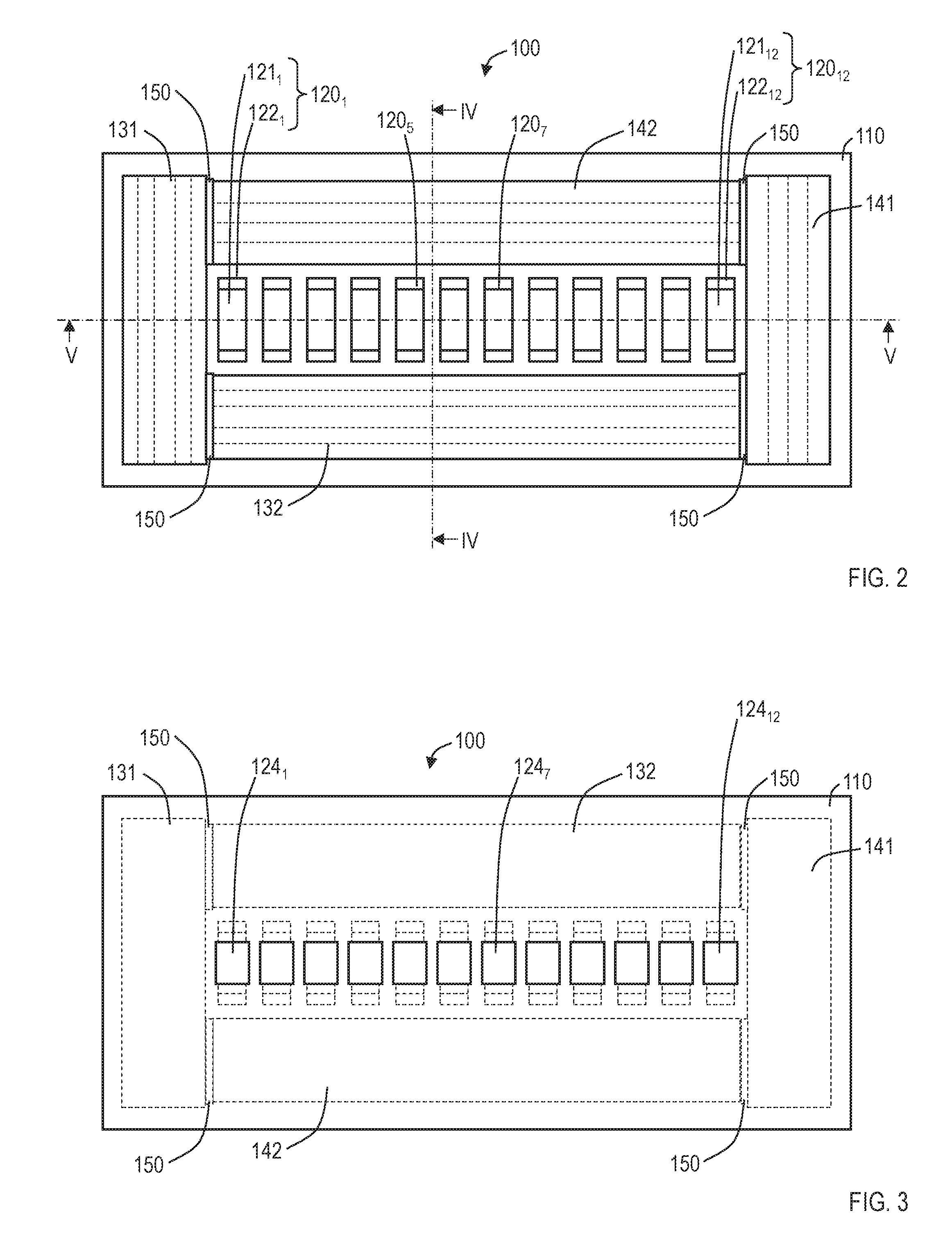
FIG. 2 is a planar view illustrating a first connector of a connector assembly according to a first embodiment.
FIG. 3 is a rear view illustrating the first connector of the connector assembly according to the first embodiment.
FIG. 4 is a sectional view taken along the line IV-IV of FIG. 2.
FIG. 5 is a sectional view taken along the line V-V of FIG. 2.
FIG. 6 is a sectional view on the IV-IV position of FIG. 2 in a case where fasteners of the first connector and fasteners of a second connector, which are respectively opposed to each other, of the connector assembly according to the first embodiment are respectively engaged with each other.
FIG. 7 is a sectional view on the V-V position of FIG. 2 in a case where the fasteners of the first connector and the fasteners of the second connector, which are respectively opposed to each other, of the connector assembly according to the first embodiment are respectively engaged with each other.
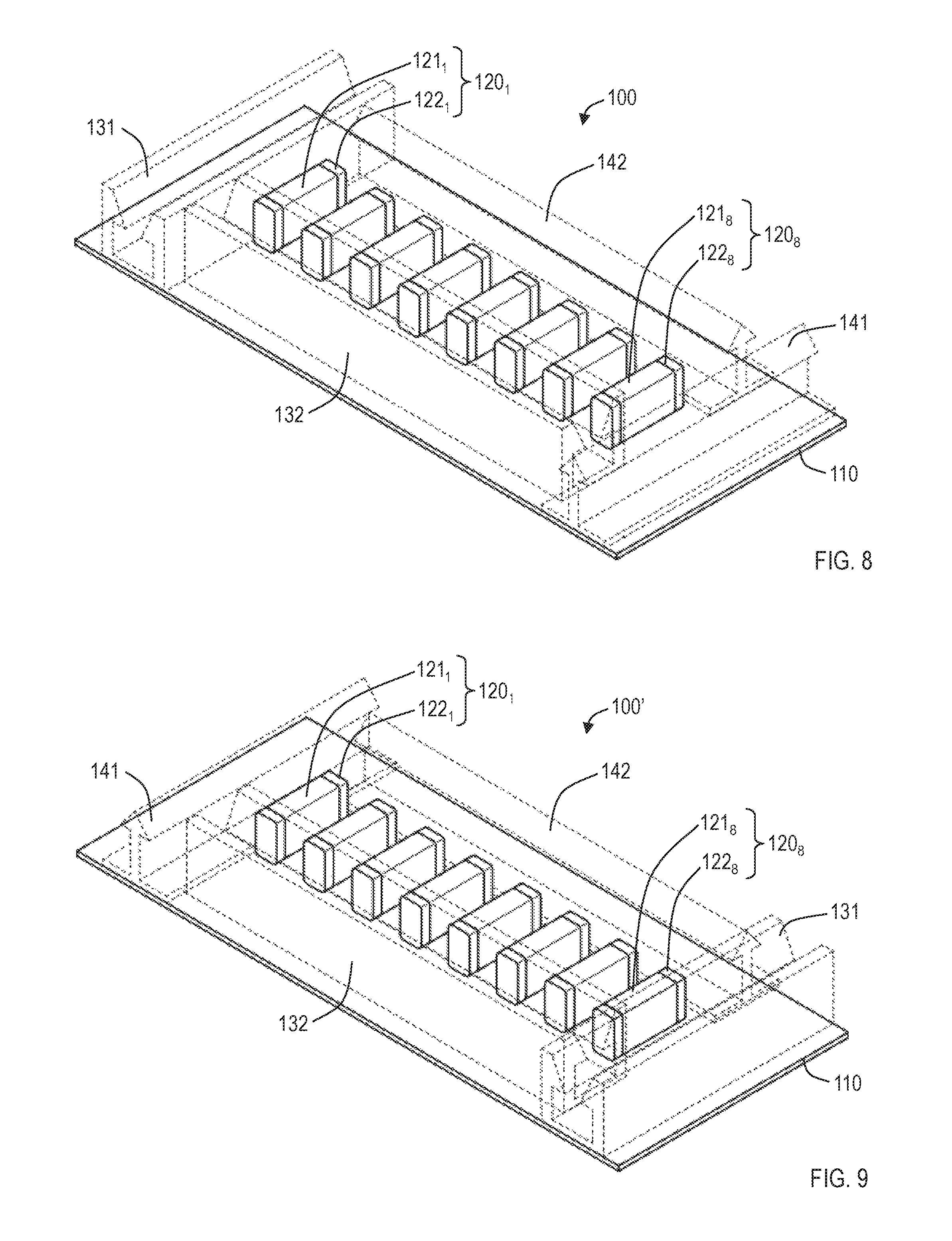
FIG. 8 is a perspective view illustrating the first connector of the connector assembly according to the first embodiment.
FIG. 9 is a perspective view illustrating the second connector of the connector assembly according to the first embodiment.
FIG. 10 is a planar view illustrating a first connector of a connector assembly according to the second embodiment.
FIG. 11 is a rear view illustrating the first connector of the connector assembly according to the second embodiment.
FIG. 12 is a sectional view taken along the line XII-XII of FIG. 10.
FIG. 13 is a sectional view taken along the line XIII-XIII of FIG. 10.
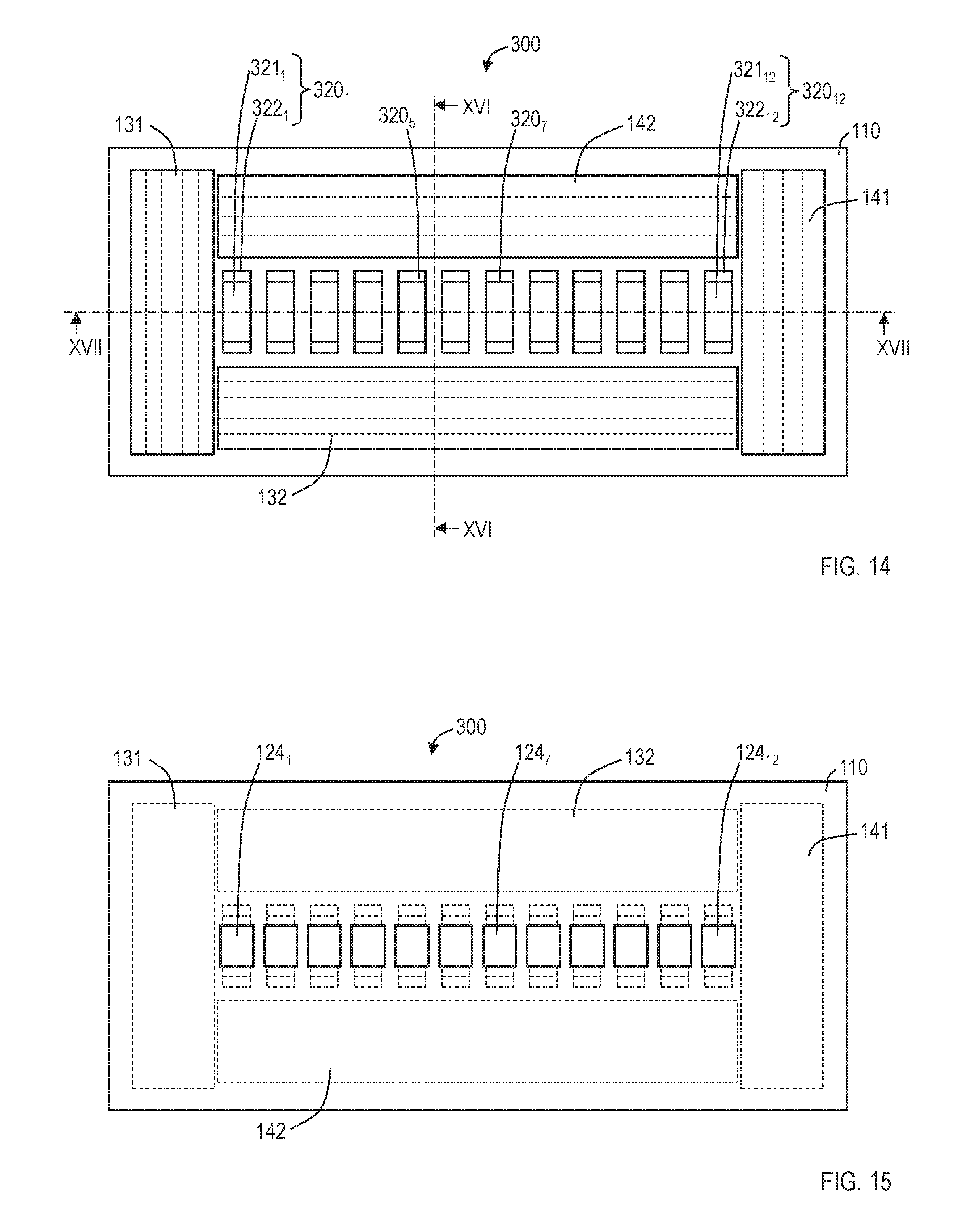
FIG. 14 is a planar view illustrating a second connector of the connector assembly according to the second embodiment.
FIG. 15 is a rear view illustrating the second connector of the connector assembly according to the second embodiment.
FIG. 16 is a sectional view taken along the line XVI-XVI of FIG. 14.
FIG. 17 is a sectional view taken along the line XVII-XVII of FIG. 14.
FIG. 18 is a sectional view on the XVI-XVI position of FIG. 14 in a case where fasteners of the first connector and fasteners of the second connector, which are respectively opposed to each other, of the connector assembly according to the second embodiment are respectively engaged with each other.
FIG. 19 is a sectional view on the XVII-XVII position of FIG. 14 in a case where the fasteners of the first connector and the fasteners of the second connector, which are respectively opposed to each other, of the connector assembly according to the second embodiment are respectively engaged with each other.
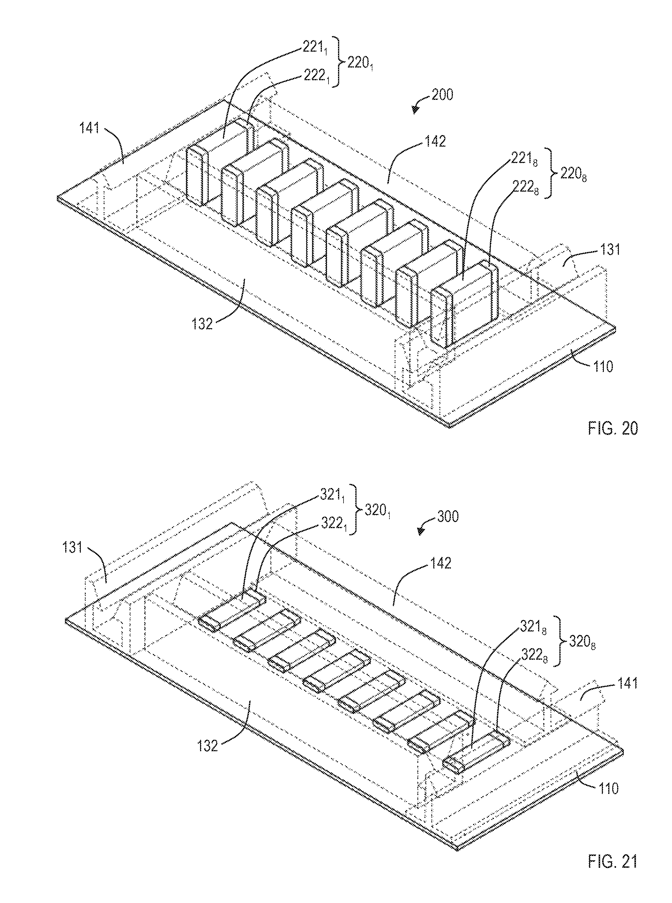
FIG. 20 is a perspective view illustrating the first connector of the connector assembly according to the second embodiment.
FIG. 21 is a perspective view illustrating the second connector of the connector assembly according to the second embodiment.
FIG. 22 is a planar view illustrating a first connector of a connector assembly according to the third embodiment and a first modification related to the third embodiment.
FIG. 23 is a rear view illustrating the first connector of the connector assembly according to the third embodiment and the first modification related to the third embodiment.
FIG. 24 is a sectional view taken along the line XXIV-XXIV of FIG. 22.
FIG. 25 is a sectional view taken along the line XXV-XXV of FIG. 22 in the case of the third embodiment.
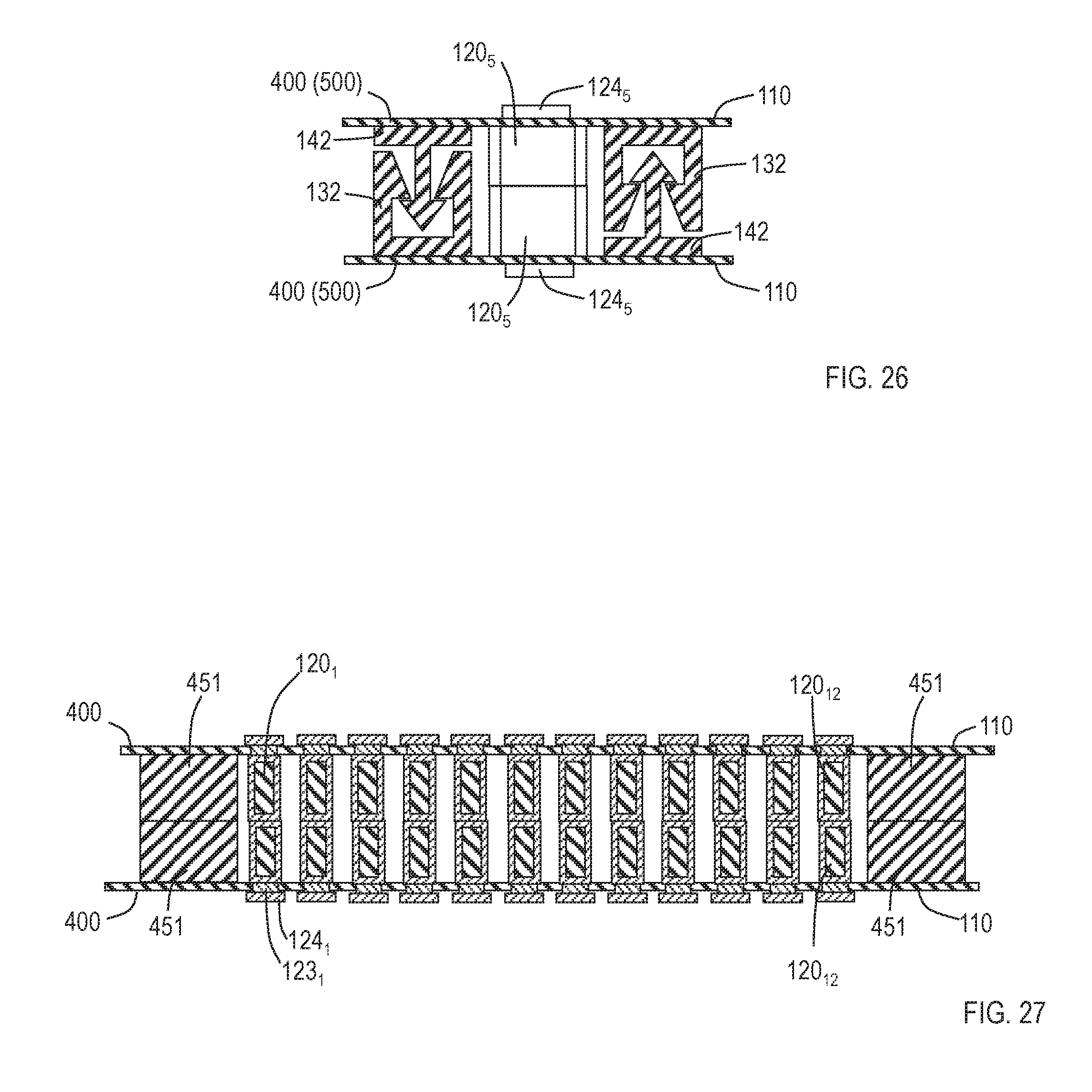
FIG. 26 is a sectional view on the XXIV-XXIV position of FIG. 22 in a case where fasteners of the first connector and fasteners of a second connector, which are respectively opposed to each other, of the connector assembly according to the third embodiment and the first modification related to the third embodiment are respectively engaged with each other.
FIG. 27 is a sectional view on the XXV-XXV position of FIG. 22 in a case where the fasteners of the first connector and the fasteners of the second connector, which are respectively opposed to each other, of the connector assembly according to the third embodiment are respectively engaged with each other.
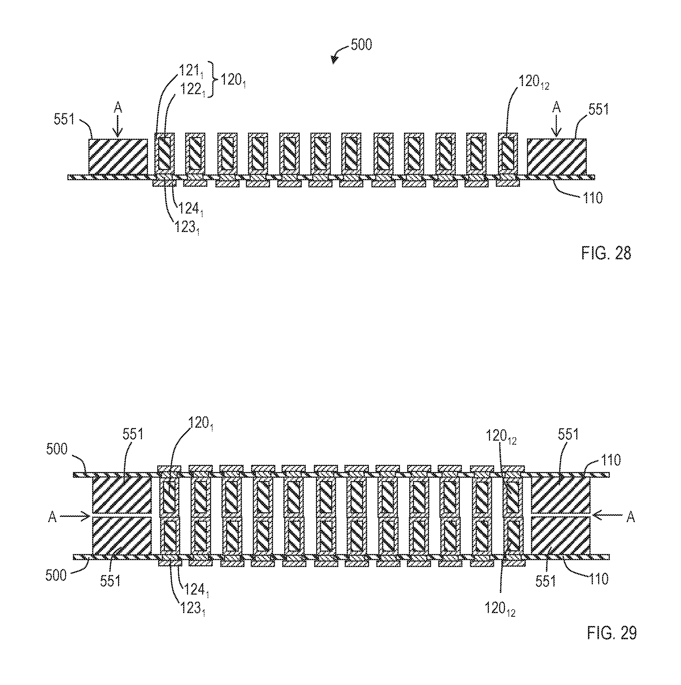
FIG. 28 is a sectional view taken along the line XXV-XXV of FIG. 22 in the case of the first modification related to the third embodiment.
FIG. 29 is a sectional view on the XXV-XXV position of FIG. 22 in a case where the fasteners of the first connector and the fasteners of the second connector, which are respectively opposed to each other, of the connector assembly according to the first modification related to the third embodiment are respectively engaged with each other.
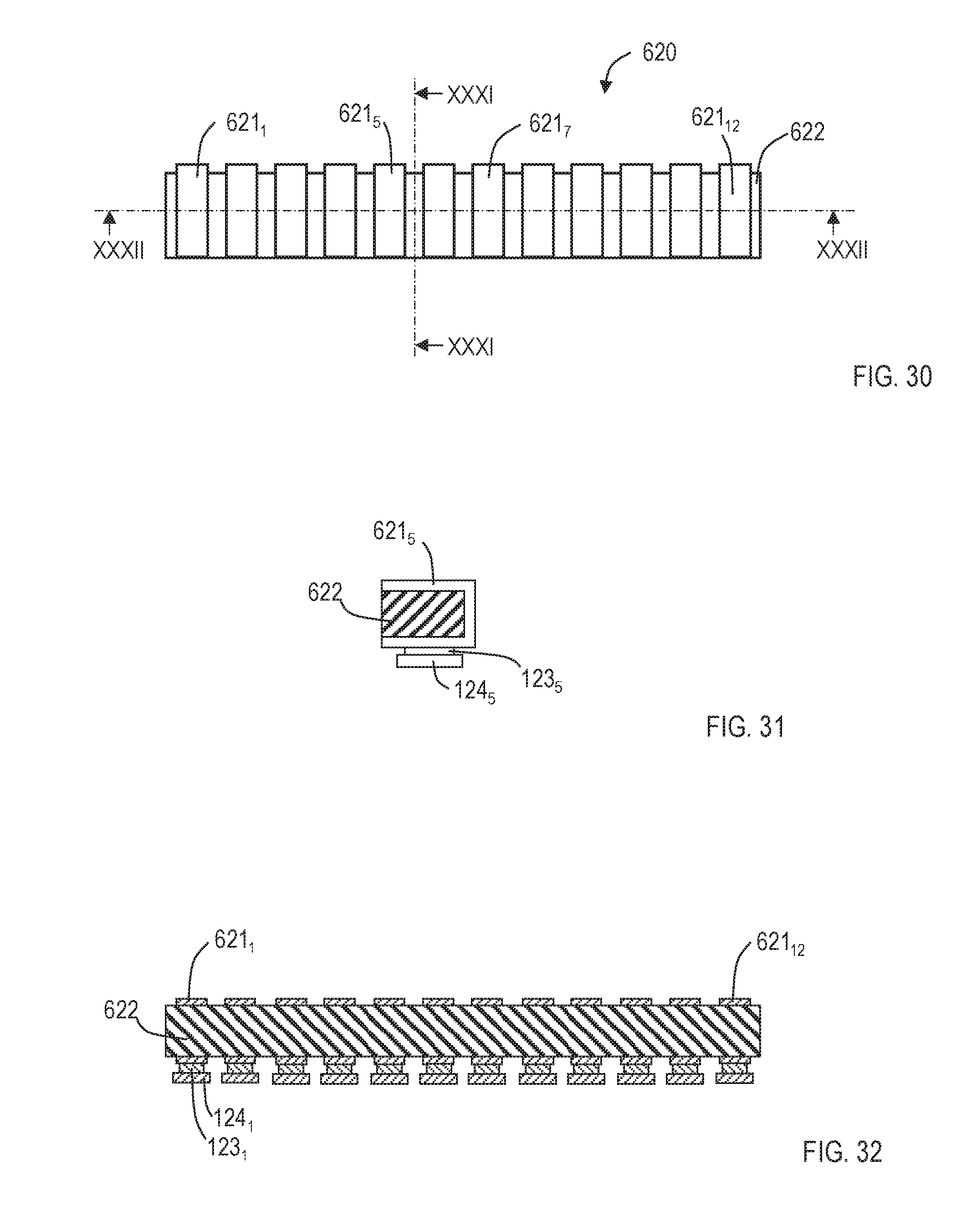
FIG. 30 is a planar view illustrating electrical connection members.
FIG. 31 is a sectional view taken along the line XXXI-XXXI of FIG. 30 and including a through conductive portion and a conductor on a rear face.
FIG. 32 is a sectional view taken along the line XXXII-XXXII of FIG. 30 and including through conductive portions and conductors on the rear face.
DETAILED DESCRIPTION OF THE EMBODIMENTS
Embodiments of the present invention will be described in detail below. Components having the same functions as each other will be denoted with the same reference numerals and duplicate description thereof will be omitted.
First Embodiment
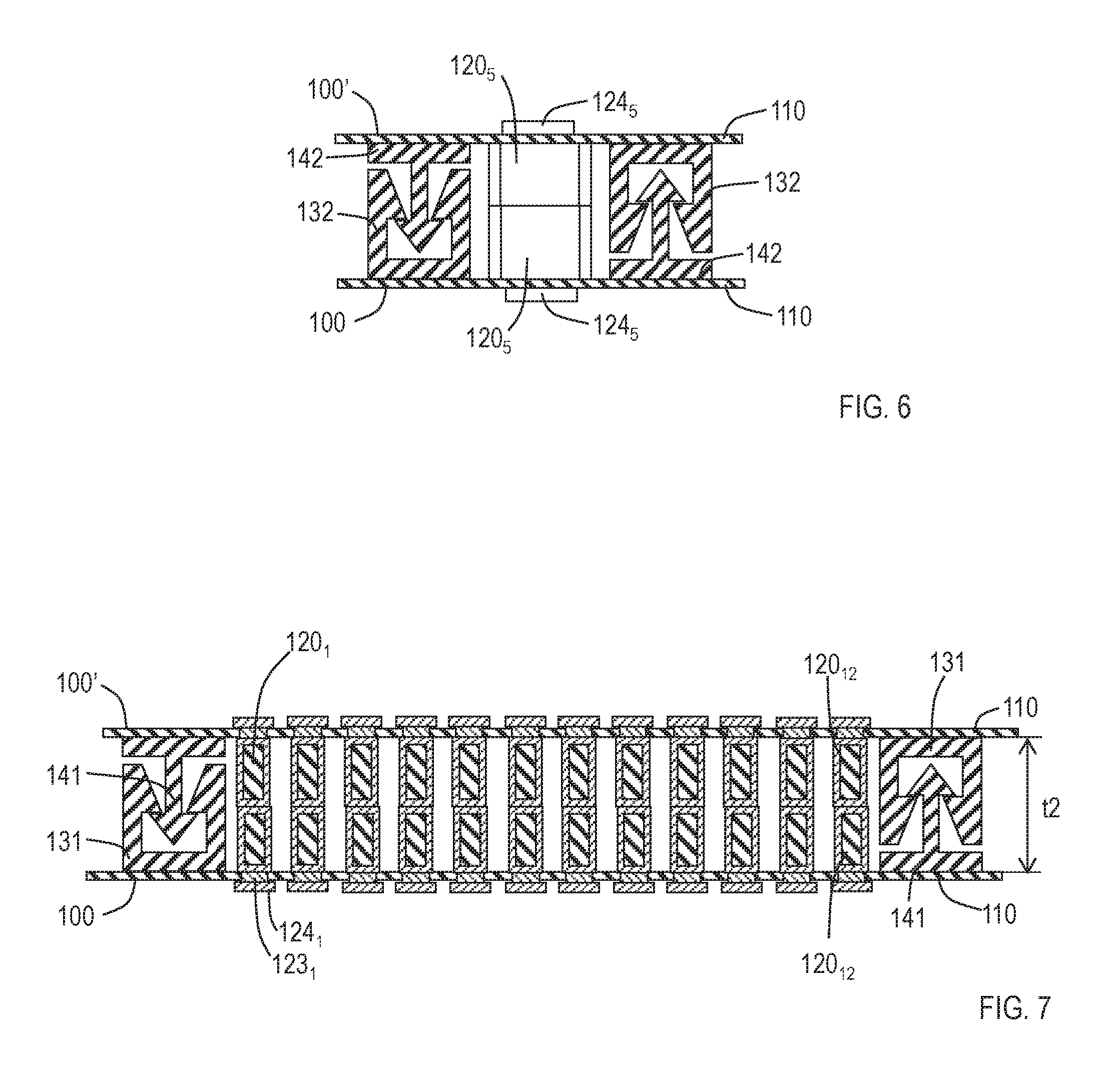
FIG. 2 is a planar view illustrating a first connector of a connector assembly according to a first embodiment. FIG. 3 is a rear view illustrating the first connector of the connector assembly according to the first embodiment. FIG. 4 is a sectional view taken along the line IV-IV of FIG. 2. FIG. 5 is a sectional view taken along the line V-V of FIG. 2. FIG. 6 is a sectional view on the IV-IV position of FIG. 2 in a case where fasteners of the first connector and fasteners of a second connector, which are respectively opposed to each other, of the connector assembly according to the first embodiment are respectively engaged with each other (the first connector is illustrated on the lower side). FIG. 7 is a sectional view on the V-V position of FIG. 2 in a case where the fasteners of the first connector and the fasteners of the second connector, which are respectively opposed to each other, of the connector assembly according to the first embodiment are respectively engaged with each other (the first connector is illustrated on the lower side). FIG. 8 is a perspective view illustrating the first connector of the connector assembly according to the first embodiment. FIG. 9 is a perspective view illustrating the second connector of the connector assembly according to the first embodiment. In FIG. 8 and FIG. 9, fasteners 131, 132, 141, and 142 are drawn by dotted lines so as to facilitate understanding of the whole shape and accordingly, parts actually concealed by the fasteners 131, 132, 141, and 142 are also illustrated. As illustrated in FIG. 8 and FIG. 9, arrangement on a first connector 100 and arrangement on a second connector 100' in the first embodiment are the same as each other except for the fasteners 131 and the fasteners 141 which are respectively arranged on inverted positions. Further, FIGS. 2 to 7 illustrate an example in which twelve pieces of first electrical connection members are provided, while FIG. 8 illustrates an example in which eight pieces of first electrical connection members are provided. In FIG. 9, the second connector which is connected with the first connector of FIG. 8 is illustrated and includes eight pieces of second electrical connection members. Thus, the number of the first electrical connection members and the number of the second electrical connection members do not have to be limited and may be determined in accordance with the application.
The connector assembly according to the first embodiment includes the first connector 100 which has first electrical connection members 120.sub.1, . . . , 120.sub.12 arranged on a base material 110 made of resin and the second connector 100' which has second electrical connection members 120.sub.1, . . . , 120.sub.12 on positions respectively opposed to the first electrical connection members 120.sub.1, . . . , 120.sub.12 on a base material 110 made of resin. The first connector 100 and the second connector 100' further include the fasteners 131, 132, 141, and 142 which are made of resin, are engageable, and are integrated with respectively-corresponding base materials 110, on mutually-opposed positions. The fasteners 131, 132, 141, and 142 of the first connector 100 form a polygonal shape which surrounds the first electrical connection members 120.sub.1, . . . , 120.sub.12 and the fasteners 131, 132, 141, and 142 of the second connector 100' form a polygonal shape which surrounds the second electrical connection members 120.sub.1, . . . , 120.sub.12. The fasteners 131, 132, 141, and 142 have water-tightness when they are engaged with corresponding fasteners. That is, water cannot infiltrate from parts on which the fasteners 131, 132, 141, and 142 are engaged with corresponding fasteners. By engaging the fasteners 131, 132, 141, and 142 of the first connector 100 and the fasteners 141, 142, 131, and 132 of the second connector 100' which are respectively opposed to each other, the first electrical connection members 120.sub.1, . . . , 120.sub.12 and the second electrical connection members 120.sub.1, . . . , 120.sub.12 are respectively brought into contact with each other. FIGS. 2 to 9 illustrate a case where the fasteners form a rectangular shape. However, the fasteners may form another polygonal shape such as a hexagonal shape. Further, in FIGS. 2 to 9, both of inner sides of the fasteners (sides closer to the first electrical connection members 120.sub.1, . . . , 120.sub.12) and outer sides form rectangular shapes. However, in a case where the fasteners form another polygonal shape, it is sufficient that the inner sides of the fasteners form the polygonal shape, and the outer sides of the fasteners do not have to be brought into contact with each other.
When the base material 110 is composed of a high density polyethylene film having the thickness of 50 to 100 .mu.m, for example, the base material 110 exhibits flexibility. Further, a fastener described in Patent Literature 2, for example, may be employed as the fasteners 131, 132, 141, and 142. The fasteners 131, 132, 141, and 142 may be made with low density polyethylene and formed in a strip-like shape to be integrated with the base material 110. Through such formation, the fasteners 131, 132, 141, and 142 can obtain water-tightness in engagement thereof "Integration" represents a state of adhesion through thermal fusion or with an adhesive, for example. The fasteners 131, 132, 141, and 142 may be formed to have the height of approximately 1.5 mm and the width of approximately 1.5 mm. The length of the fasteners 131, 132, 141, and 142 may be determined in accordance with the number or the size of the first electrical connection members. Further, in a case where gaps among the fasteners 131, 132, 141, and 142 have a width unignorable with respect to required waterproofness, seal members 150 may be provided in the gaps among the fasteners 131, 132, 141, and 142. In this case, the seal members 150, which are opposed to each other, of the first connector 100 and the second connector 100' are brought into contact with each other when the fasteners 131, 132, 141, and 142 of the first connector 100 and the fasteners 141, 142, 131, and 132 of the second connector 100' are engaged with each other. Accordingly, the waterproofness can be enhanced. Here, in a case where gaps among the fasteners 131, 132, 141, and 142 have a width ignorable with respect to required waterproofness, the seal member 150 does not have to be provided. Further, the waterproofness may be enhanced by applying water repellent treatment to gap parts among the fasteners 131, 132, 141, and 142. Further, the fasteners 131, 132, 141, and 142 not only secure the waterproofness but also have a role for positioning.
The first electrical connection members 120.sub.1, . . . , 120.sub.12 and the second electrical connection members 120.sub.1, . . . , 120.sub.12 have the configurations in which conductors 121.sub.1, . . . , 121.sub.12 are bonded around elastic members 122.sub.1, . . . , 122.sub.12 respectively. Examples of a material of the elastic members 122.sub.1, . . . , 122.sub.12 include elastomer, polyurethane, polyester, polyamide, polystyrene, polyolefin, vinyl chloride, styrene-butadiene rubber, chloroprene rubber, and ethylene-propylene rubber. However, the material is not limited to these. The conductors 121.sub.1, . . . , 121.sub.12 may be made of a copper film, for example.
Through holes are formed on the base material 110 so as to secure conductivity between an upper face and a rear face of the base material 110. Through conductive portions 123.sub.1, . . . , 123.sub.12 are respectively arranged so as to fill the through holes and be connected with the conductors 121.sub.1, . . . , 121.sub.12. Further, conductors 124.sub.1, . . . , 124.sub.12 are arranged on positions, on which the conductors 124.sub.1, . . . , 124.sub.12 are respectively connected with the through conductive portions 123.sub.1, . . . , 123.sub.12, on the rear face of the base material 110. Here, a conductive adhesive may be used as a material of the through conductive portions 123.sub.1, . . . , 123.sub.12. Further, the conductors 124.sub.1, . . . , 124.sub.12 may be made of a copper film.
For example, the height (t1 in FIG. 5), the width (the longer direction in the planar view of FIG. 2), and the thickness (the shorter direction in the planar view of FIG. 2) of the first electrical connection members 120.sub.1, . . . , 120.sub.12 may be respectively set to approximately 0.9 mm, approximately 3 mm, and approximately 1 mm, and the interval among the first electrical connection members 120.sub.1, . . . , 120.sub.12 may be set to approximately 1 mm. The same goes for the second electrical connection members 120.sub.1, . . . , 120.sub.12. An interval (t2 in FIG. 7) between the base materials 110 in a state that the fasteners 131, 132, 141, and 142 are respectively engaged with corresponding fasteners may be set to approximately 1.7 mm. In the state of engagement, the elastic members 122.sub.1, . . . , 122.sub.12 deform and thus the first electrical connection members 120.sub.1, . . . , 120.sub.12 and the second electrical connection members 120.sub.1, 120.sub.12 are in contact with each other in a manner to push against each other. A relationship between t1 and t2 may be set as appropriate based on a mutual pushing force required in engagement, an elastic modulus of the elastic members 122.sub.1, . . . , 122.sub.12, and the like. That is, the first electrical connection members 120.sub.1, . . . , 120.sub.12 and the second electrical connection members 120.sub.1, . . . , 120.sub.12 have elasticity in a normal direction of the base material 110.
According to the connector assembly of the first embodiment, when the fasteners are engaged with each other, the first electrical connection members and the second electrical connection members are brought into contact with each other in a manner to push against each other. Further, positioning and fixing can be performed with the fasteners, facilitating attachment and detachment. Furthermore, the fasteners have water-tightness, so that infiltration of water drops from a gap between the fasteners is limited. Thus, waterproofness in a living environment or in a similar environment can be secured.
Second Embodiment
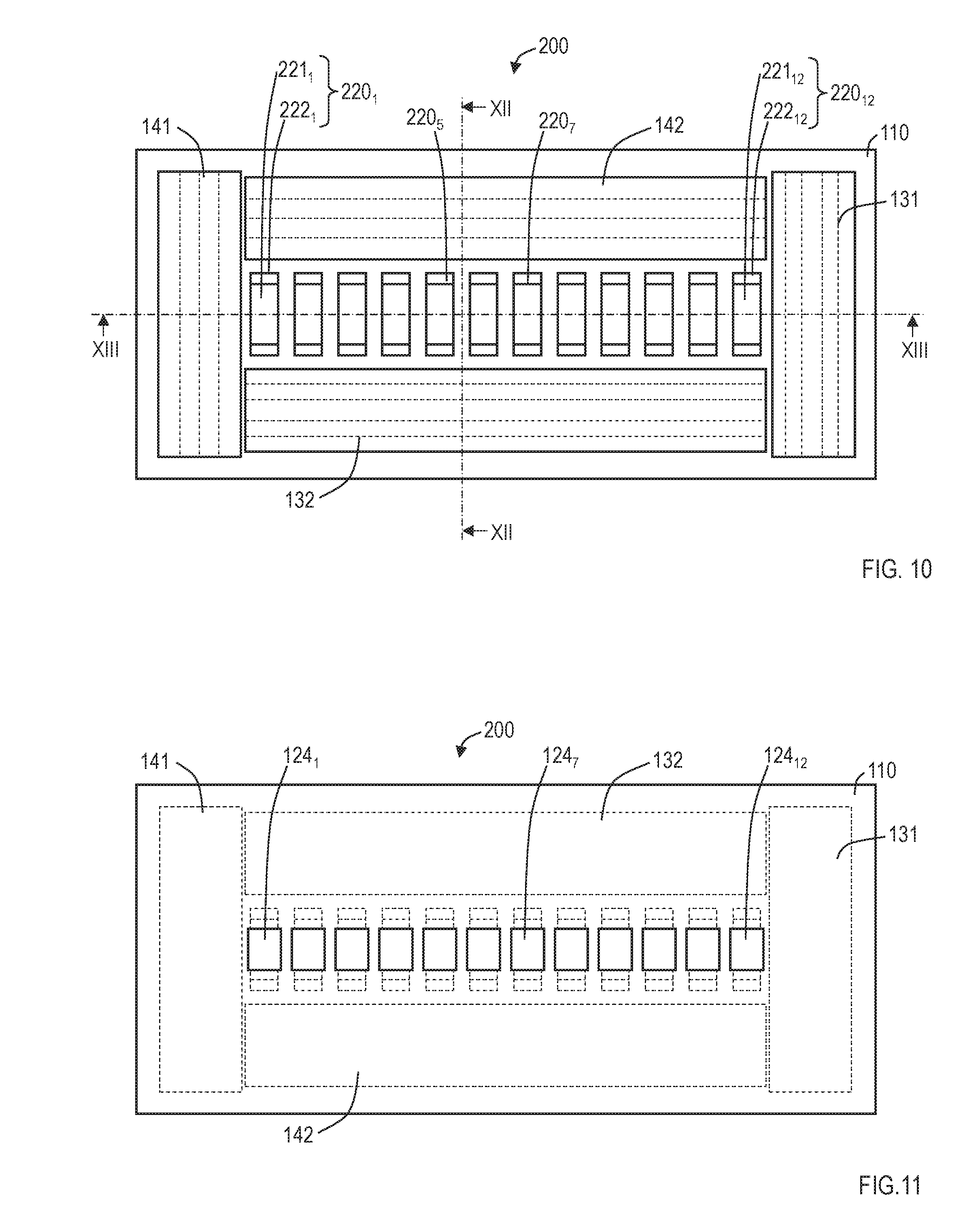
FIG. 10 is a planar view illustrating a first connector of a connector assembly according to a second embodiment. FIG. 11 is a rear view illustrating the first connector of the connector assembly according to the second embodiment. FIG. 12 is a sectional view taken along the line XII-XII of FIG. 10. FIG. 13 is a sectional view taken along the line XIII-XIII of FIG. 10. FIG. 14 is a planar view illustrating a second connector of the connector assembly according to the second embodiment. FIG. 15 is a rear view illustrating the second connector of the connector assembly according to the second embodiment. FIG. 16 is a sectional view taken along the line XVI-XVI of FIG. 14. FIG. 17 is a sectional view taken along the line XVII-XVII of FIG. 14. FIG. 18 is a sectional view on the XVI-XVI position of FIG. 14 in a case where fasteners of the first connector and fasteners of the second connector, which are respectively opposed to each other, of the connector assembly according to the second embodiment are respectively engaged with each other (the second connector is illustrated on the lower side). FIG. 19 is a sectional view on the XVII-XVII position of FIG. 14 in a case where the fasteners of the first connector and the fasteners of the second connector, which are respectively opposed to each other, of the connector assembly according to the second embodiment are respectively engaged with each other (the second connector is illustrated on the lower side). FIG. 20 is a perspective view illustrating the first connector of the connector assembly according to the second embodiment, and FIG. 21 is a perspective view illustrating the second connector of the connector assembly according to the second embodiment. In FIG. 20 and FIG. 21, fasteners 131, 132, 141, and 142 are drawn by dotted lines so as to facilitate understanding of the whole shape and accordingly, parts actually concealed by the fasteners 131, 132, 141, and 142 are also illustrated. Further, FIGS. 10 to 19 illustrate an example in which twelve pieces of first electrical connection members and twelve pieces of second electrical connection members are provided, while FIG. 20 and FIG. 21 illustrate an example in which eight pieces of first electrical connection members and eight pieces of second electrical connection members are provided. As is the case with the first embodiment, the number of the first electrical connection members and the number of the second electrical connection members do not have to be limited and may be determined in accordance with the application.
The connector assembly according to the second embodiment includes a first connector 200 which has first electrical connection members 220.sub.1, . . . , 220.sub.12 arranged on a base material 110 made of resin and a second connector 300 which has second electrical connection members 320.sub.1, . . . , 320.sub.12 on positions respectively opposed to the first electrical connection members 220.sub.1, . . . , 220.sub.12 on a base material 110 made of resin. The first connector 200 and the second connector 300 further include the fasteners 131, 132, 141, and 142 which are made of resin, are engageable, and are integrated with respectively-corresponding base materials 110, on mutually-opposed positions. The fasteners 131, 132, 141, and 142 of the first connector 200 form a polygonal shape which surrounds the first electrical connection members 220.sub.1, . . . , 220.sub.12 and the fasteners 131, 132, 141, and 142 of the second connector 300 form a polygonal shape which surrounds the second electrical connection members 320.sub.1, . . . , 320.sub.12. The fasteners 131, 132, 141, and 142 have water-tightness when they are engaged with corresponding fasteners. By engaging the fasteners 131, 132, 141, and 142 of the first connector 200 and the fasteners 141, 142, 131, and 132 of the second connector 300 which are respectively opposed to each other, the first electrical connection members 220.sub.1, . . . , 220.sub.12 and the second electrical connection members 320.sub.1, . . . , 320.sub.12 are respectively brought into contact with each other. FIGS. 10 to 21 illustrate a case where the fasteners form a rectangular shape. However, the fasteners may form another polygonal shape such as a hexagonal shape. Further, in FIGS. 10 to 21, both of inner sides of the fasteners (sides closer to the first electrical connection members 220.sub.1, . . . , 220.sub.12) and outer sides form rectangular shapes. However, in a case where the fasteners form another polygonal shape, it is sufficient that the inner sides of the fasteners form the polygonal shape, and the outer sides of the fasteners do not have to be brought into contact with each other. The base material 110 and the fasteners 131, 132, 141, and 142 are same as those of the first embodiment. Further, the seal members 150 and water repellent treatment among the fasteners 131, 132, 141, and 142 are same as those of the first embodiment.
The first electrical connection members 220.sub.1, . . . , 220.sub.12 have the configuration in which conductors 221.sub.1, . . . , 221.sub.12 are bonded around elastic members 222.sub.1, . . . , 222.sub.12 respectively. The second electrical connection members 320.sub.1, . . . , 320.sub.12 may have the configuration in which conductors 321.sub.1, . . . , 321.sub.12 are bonded around elastic members 322.sub.1, . . . , 322.sub.12 respectively or the configuration in which the conductors 321.sub.1, . . . , 321.sub.12 are made of copper plates or the like without using elastic members. A material of the elastic members 222.sub.1, . . . , 222.sub.12 is the same as that in the first embodiment. Further, the conductors 221.sub.1, . . . , 221.sub.12 and the conductors 321.sub.1, . . . , 321.sub.12 may be made of copper films, for example. Through conductive portions 123.sub.1, 123.sub.12 and conductors 124.sub.1, . . . , 124.sub.12 are the same as those in the first embodiment.
For example, the height, the width (the longer direction in the planar view of FIG. 10), and the thickness (the shorter direction in the planar view of FIG. 10) of the first electrical connection members 220.sub.1, . . . , 220.sub.12 may be respectively set to approximately 1.6 mm, approximately 3 mm, and approximately 1 mm, and the interval among the first electrical connection members 220.sub.1, . . . , 220.sub.12 may be set to approximately 1 mm. The height, the width (the longer direction in the planar view of FIG. 14), and the thickness (the shorter direction in the planar view of FIG. 14) of the second electrical connection members 320.sub.1, . . . , 320.sub.12 may be respectively set to approximately 0.2 mm, approximately 3 mm, and approximately 1 mm, and the interval among the second electrical connection members 320.sub.1, . . . , 320.sub.12 may be set to approximately 1 mm. An interval between the base materials 110 in a state that the fasteners 131, 132, 141, and 142 are respectively engaged with corresponding fasteners may be set to approximately 1.7 mm. In the state of engagement, the elastic members 222.sub.1, . . . , 222.sub.12 of the first electrical connection members 220.sub.1, . . . , 220.sub.12 deform and thus the first electrical connection members 220.sub.1, . . . , 220.sub.12 and the second electrical connection members 320.sub.1, . . . , 320.sub.12 are in contact with each other in a manner to push against each other. The height of the first electrical connection members 220.sub.1, . . . , 220.sub.12 may be set as appropriate based on a mutual pushing force required in engagement, an elastic modulus of the elastic members 222.sub.1, . . . , 222.sub.12, and the like. That is, at least the first electrical connection members 220.sub.1, . . . , 220.sub.12 have elasticity in the normal direction of the base material 110.
The connector assembly according to the second embodiment has the configuration as that described above, being able to exhibit a similar advantageous effect to that of the connector assembly according to the first embodiment.
Third Embodiment
FIG. 22 is a planar view illustrating a first connector of a connector assembly according to a third embodiment. FIG. 23 is a rear view illustrating the first connector of the connector assembly according to the third embodiment. FIG. 24 is a sectional view taken along the line XXIV-XXIV of FIG. 22. FIG. 25 is a sectional view taken along the line XXV-XXV of FIG. 22. FIG. 26 is a sectional view on the XXIV-XXIV position of FIG. 22 in a case where fasteners of the first connector and fasteners of a second connector, which are respectively opposed to each other, of the connector assembly according to the third embodiment are respectively engaged with each other. FIG. 27 is a sectional view on the XXV-XXV position of FIG. 22 in a case where the fasteners of the first connector and the fasteners of the second connector, which are respectively opposed to each other, of the connector assembly according to the third embodiment are respectively engaged with each other. In the third embodiment, the configuration of a first connector 400 and the configuration of a second connector 400 are the same as each other. Further, FIGS. 22 to 27 illustrate an example in which twelve pieces of first electrical connection members are provided. However, the number of the first electrical connection members and the number of second electrical connection members do not have to be limited and may be determined in accordance with the application.
The connector assembly according to the third embodiment includes the first connector 400 which has first electrical connection members 120.sub.1, . . . , 120.sub.12 arranged on a base material 110 made of resin and the second connector 400 which has second electrical connection members 120.sub.1, 120.sub.12 on positions respectively opposed to the first electrical connection members 120.sub.1, . . . , 120.sub.12 on a base material 110 made of resin. The first connector 400 and the second connector 400 further include the fasteners 132 and 142 which are made of resin, are engageable, and are integrated with respectively-corresponding base materials 110, on mutually-opposed positions. Each of the first connector 400 and the second connector 400 further includes seal portions 451 made of a seal member on mutually-opposed positions. The fasteners 132 and 142 and the seal portions 451 of the first connector 400 surround the first electrical connection members 120.sub.1, . . . , 120.sub.12 and the fasteners 132 and 142 and the seal portions 451 of the second connector 400 surround the second electrical connection members 120.sub.1, 120.sub.12.
The fasteners 132 and 142 have water-tightness when they are engaged with each other. By engaging the fasteners 132 and 142 of the first connector 400 and the fasteners 142 and 132 of the second connector 400 which are respectively opposed to each other, the first electrical connection members 120.sub.1, . . . , 120.sub.12 and the second electrical connection members 120.sub.1, . . . , 120.sub.12 are brought into contact with each other and the seal portions 451 are brought into contact with each other. In FIGS. 22 to 27, the fasteners 132 and 142 and the seal portions 451 form a rectangular shape and surround the first electrical connection members 120.sub.1, . . . , 120.sub.12. However, the fasteners and the seal portions may form another shape. For example, the fasteners and the seal portions may form a hexagonal shape or an octagonal shape, and the seal portion 451 may be formed to be curved. The seal portion 451 may have concavities and convexities though contacting parts are flat in FIG. 25 and FIG. 27. Further, the seal portion 451 has elasticity.
The base material 110 and the fasteners 132 and 142 are the same as those in the first embodiment. Further, the first electrical connection members 120.sub.1, . . . , 120.sub.12, the second electrical connection members 120.sub.1, . . . , 120.sub.12, through conductive portions 123.sub.1, . . . , 123.sub.12, and conductors 124.sub.1, . . . , 124.sub.12 are also the same as those in the first embodiment.
The connector assembly according to the third embodiment has the configuration as that described above, being able to exhibit a similar advantageous effect to that of the connector assembly according to the first embodiment.
First Modification
In this modification, an example in which the seal portions in the third embodiment are changed into water repellent treatment portions is described. FIG. 22 is a planar view illustrating a first connector of a connector assembly according to the present modification. FIG. 23 is a rear view illustrating the first connector of the connector assembly according to the present modification. FIG. 24 is a sectional view taken along the line XXIV-XXIV of FIG. 22. FIG. 28 is a sectional view taken along the line XXV-XXV of FIG. 22. FIG. 26 is a sectional view on the XXIV-XXIV position of FIG. 22 in a case where fasteners of the first connector and fasteners of a second connector, which are respectively opposed to each other, of the connector assembly according to the present modification are respectively engaged with each other. FIG. 29 is a sectional view on the XXV-XXV position of FIG. 22 in a case where the fasteners of the first connector and the fasteners of the second connector, which are respectively opposed to each other, of the connector assembly according to the present modification are respectively engaged with each other. In the present modification, the configuration of a first connector 500 and the configuration of a second connector 500 are the same as each other. Further, FIGS. 22 to 24, 26, 28, and 29 illustrate an example in which twelve pieces of first electrical connection members are provided. However, the number of the first electrical connection members and the number of the second electrical connection members do not have to be limited and may be determined in accordance with the application.
The connector assembly according to the present modification includes the first connector 500 which has first electrical connection members 120.sub.1, . . . , 120.sub.12 arranged on a base material 110 made of resin and the second connector 500 which has second electrical connection members 120.sub.1, . . . , 120.sub.12 on positions respectively opposed to the first electrical connection members 120.sub.1, . . . , 120.sub.12 on a base material 110 made of resin. The first connector 500 and the second connector 500 further include the fasteners 132 and 142 which are made of resin, are engageable, and are integrated with respectively-corresponding base materials 110, on mutually-opposed positions. Each of the first connector 500 and the second connector 500 further includes water repellent treatment portions 551 made of a member subjected to the water repellent treatment on mutually-opposed positions. The fasteners 132 and 142 and the water repellent treatment portions 551 of the first connector 500 surround the first electrical connection members 120.sub.1, . . . , 120.sub.12 and the fasteners 132 and 142 and the water repellent treatment portions 551 of the second connector 500 surround the second electrical connection members 120.sub.1, . . . , 120.sub.12.
The fasteners 132 and 142 have water-tightness when they are engaged with each other. By engaging the fasteners 132 and 142 of the first connector 500 and the fasteners 142 and 132 of the second connector 500 which are respectively opposed to each other, the first electrical connection members 120.sub.1, . . . , 120.sub.12 and the second electrical connection members 120.sub.1, . . . , 120.sub.12 are respectively brought into contact with each other and the water repellent treatment portions 551 mutually approach to have an interval, from which water does not infiltrate within a predetermined atmospheric pressure (for example, 2 atmospheres), or a smaller interval. In FIGS. 22 to 24, 26, 28, and 29, the fasteners 132 and 142 and the water repellent treatment portions 551 form a rectangular shape and surround the first electrical connection members 120.sub.1, . . . , 120.sub.12. However, the fasteners and the water repellent treatment portions may form another shape. For example, the fasteners and the water repellent treatment portions may form a hexagonal shape or an octagonal shape, and the water repellent treatment portion 551 may be formed to be curved. The water repellent treatment portions 551 may be formed such that water repellent treatment is applied to at least mutually opposed parts (a part denoted with A in FIG. 28). By such water repellent treatment, water infiltration from a gap denoted with A of FIG. 29 can be prevented.
The base material 110 and the fasteners 132 and 142 are the same as those in the first embodiment. Further, the first electrical connection members 120.sub.1, . . . , 120.sub.12, the second electrical connection members 120.sub.1, 120.sub.12, through conductive portions 123.sub.1, . . . , 123.sub.12, and conductors 124.sub.1, . . . , 124.sub.12 are also the same as those in the first embodiment.
The connector assembly according to the present modification has the configuration as that described above, being able to exhibit a similar advantageous effect to that of the connector assembly according to the first embodiment.
Second Modification
In this modification, modifications of the first electrical connection members and the second electrical connection members will be described. This modification is applicable to any of the first embodiment, the second embodiment, the third embodiment, and the first modification related to the third embodiment. Only one or both of the first electrical connection members and the second electrical connection members may be changed into electrical connection members which will be described below. Therefore, description will be provided below while referring to the first electrical connection member and/or the second electrical connection member merely as an "electrical connection member".
FIG. 30 is a planar view illustrating an electrical connection member (drawing viewed from the same direction as FIG. 2). FIG. 31 is a sectional view taken along the line XXXI-XXXI of FIG. 30 and including a through conductive portion and a conductor on a rear face. FIG. 32 is a sectional view taken along the line XXXII-XXXII of FIG. 30 and including through conductive portions and conductors on the rear face. An electrical connection member 620 has the configuration in which conductors 621.sub.1, . . . , 621.sub.12 are formed around an elastic member 622. The conductors 621.sub.1, . . . , 621.sub.12 are respectively connected to conductors 124.sub.1, . . . , 124.sub.12 which are arranged on a rear face of a base material 110 respectively via through conductive portions 123.sub.1, . . . , 123.sub.12. The same material as that in the first embodiment may be used for the elastic member 622. The conductors 621.sub.1, . . . , 621.sub.12 may be made of copper films or formed by performing etching after forming a thin film on the elastic member 622 by a method such as vapor deposition, sputtering, and plating.
The electrical connection member described in the present modification has the configuration as that described above, being applicable to any of the first embodiment, the second embodiment, the third embodiment, and the first modification related to the third embodiment.
The foregoing description of the embodiments of the invention has been presented for the purpose of illustration and description. It is not intended to be exhaustive and to limit the invention to the precise form disclosed. Modifications or variations are possible in light of the above teaching. The embodiment was chosen and described to provide the best illustration of the principles of the invention and its practical application, and to enable one of ordinary skill in the art to utilize the invention in various embodiments and with various modifications as are suited to the particular use contemplated. All such modifications and variations are within the scope of the invention as determined by the appended claims when interpreted in accordance with the breadth to which they are fairly, legally, and equitably entitled.
* * * * *
D00000
D00001
D00002
D00003
D00004
D00005
D00006
D00007
D00008
D00009
D00010
D00011
D00012

D00013

D00014
D00015
D00016
XML
uspto.report is an independent third-party trademark research tool that is not affiliated, endorsed, or sponsored by the United States Patent and Trademark Office (USPTO) or any other governmental organization. The information provided by uspto.report is based on publicly available data at the time of writing and is intended for informational purposes only.
While we strive to provide accurate and up-to-date information, we do not guarantee the accuracy, completeness, reliability, or suitability of the information displayed on this site. The use of this site is at your own risk. Any reliance you place on such information is therefore strictly at your own risk.
All official trademark data, including owner information, should be verified by visiting the official USPTO website at www.uspto.gov. This site is not intended to replace professional legal advice and should not be used as a substitute for consulting with a legal professional who is knowledgeable about trademark law.