CO.sub.2 concentration reducing device
Yoshikawa , et al. Oc
U.S. patent number 10,456,731 [Application Number 15/546,814] was granted by the patent office on 2019-10-29 for co.sub.2 concentration reducing device. This patent grant is currently assigned to HITACHI CHEMICAL COMPANY, LTD.. The grantee listed for this patent is HITACHI CHEMICAL COMPANY, LTD.. Invention is credited to Masato Kaneeda, Hidehiro Nakamura, Toshiaki Shirasaka, Kohei Yoshikawa.


| United States Patent | 10,456,731 |
| Yoshikawa , et al. | October 29, 2019 |
CO.sub.2 concentration reducing device
Abstract
Disclosed is a CO.sub.2 concentration reducing device for separating and removing CO.sub.2 from a gas containing CO.sub.2 with a CO.sub.2 adsorbent, the CO.sub.2 concentration reducing device including: an adsorbent container which contains the CO.sub.2 adsorbent; and a heating unit which heats the CO.sub.2 adsorbent by an induction heating or a dielectric heating. Thus, a ventilation quantity can be reduced when CO.sub.2 accumulated in a room is removed, and an electric power required for the ventilation and the electric power required for air conditioning can be reduced.
| Inventors: | Yoshikawa; Kohei (Tokyo, JP), Kaneeda; Masato (Tokyo, JP), Nakamura; Hidehiro (Tokyo, JP), Shirasaka; Toshiaki (Tokyo, JP) | ||||||||||
|---|---|---|---|---|---|---|---|---|---|---|---|
| Applicant: |
|
||||||||||
| Assignee: | HITACHI CHEMICAL COMPANY, LTD.
(Tokyo, JP) |
||||||||||
| Family ID: | 56977232 | ||||||||||
| Appl. No.: | 15/546,814 | ||||||||||
| Filed: | February 24, 2016 | ||||||||||
| PCT Filed: | February 24, 2016 | ||||||||||
| PCT No.: | PCT/JP2016/055383 | ||||||||||
| 371(c)(1),(2),(4) Date: | July 27, 2017 | ||||||||||
| PCT Pub. No.: | WO2016/152363 | ||||||||||
| PCT Pub. Date: | September 29, 2016 |
Prior Publication Data
| Document Identifier | Publication Date | |
|---|---|---|
| US 20180021717 A1 | Jan 25, 2018 | |
Foreign Application Priority Data
| Mar 26, 2015 [JP] | 2015-064101 | |||
| Current U.S. Class: | 1/1 |
| Current CPC Class: | B01D 53/04 (20130101); B01J 20/3433 (20130101); B01J 20/3483 (20130101); B01D 53/0438 (20130101); B01J 20/06 (20130101); B01D 53/12 (20130101); B01D 2259/4508 (20130101); B01D 2259/40098 (20130101); Y02C 20/40 (20200801); B01D 2253/1124 (20130101); B01D 2253/104 (20130101); B01D 2257/504 (20130101); B01D 2259/40096 (20130101); B01D 2259/4566 (20130101); B01D 2253/106 (20130101); B01D 2258/06 (20130101); B01D 2255/2065 (20130101); Y02C 10/08 (20130101) |
| Current International Class: | B01D 53/52 (20060101); B01J 20/34 (20060101); B01D 53/04 (20060101); B01J 20/06 (20060101); B01D 53/12 (20060101) |
| Field of Search: | ;95/139,148 ;96/146 |
References Cited [Referenced By]
U.S. Patent Documents
| 3907971 | September 1975 | Bohm et al. |
| 2007/0169624 | July 2007 | Saito |
| 2012/0025134 | February 2012 | Feng |
| 2012/0048111 | March 2012 | Nakao et al. |
| 2014/0053729 | February 2014 | Crooks et al. |
| 2463013 | Jun 2012 | EP | |||
| 47-010216 | May 1972 | JP | |||
| 09-038460 | Feb 1997 | JP | |||
| 2005-194132 | Jul 2005 | JP | |||
| 2005-279390 | Oct 2005 | JP | |||
| 2012-024648 | Feb 2012 | JP | |||
| 2013-128908 | Jul 2013 | JP | |||
Other References
|
International Search Report for WO 2010/100739 A1, dated Mar. 29, 2016. cited by applicant . Liu et al., "Fundamental and practical developments of magnetofluidized beds: a review," Powder Technology, 64, 3-41 (1991). cited by applicant. |
Primary Examiner: Dang; Thuan D
Attorney, Agent or Firm: Volpe and Koenig, P.C.
Claims
The invention claimed is:
1. A device for separating and removing CO2 from a gas containing CO2, the device comprising: a magnetic body; a plurality of CO2 adsorbent particles that are formed on the magnet body an adsorbent container which contains the magnetic body; and a heating unit which heats the plurality of CO2 adsorbent particles by an induction heating.
2. The device according to claim 1, wherein the plurality of CO2 adsorbent particles contain a cerium oxide or a cerium composite oxide.
3. The device according to claim 1, wherein the magnetic body has a a linear shape, a spiral shape, or an annular shape.
4. The device according to claim 1, wherein the magnetic body is an alloy or a chemical compound containing at least one kind selected from the group consisting of iron, chromium, and cobalt.
5. The device according to claim 1, wherein a binder bonds the plurality of CO2 adsorbent particles and the magnetic body.
6. The device according to claim 5, wherein the binder contains a silicon compound or an aluminum compound.
7. The device according to claim 1, wherein the heating unit is disposed outside the adsorbent container.
8. The device according to claim 1, wherein the heating unit can locally heat a portion of the plurality of CO2 adsorbent particles by changing a position of heating.
9. The device according to claim 1, wherein the plurality of CO2 adsorbent particles adsorb and desorb CO2 in a fluidized-bed style.
Description
TECHNICAL FIELD
The present invention relates to a CO.sub.2 concentration reducing device.
BACKGROUND ART
A CO.sub.2 concentration (carbon dioxide concentration) in a room tends to rise by human breathing in a highly populated space such as a building or a vehicle. It is known that sleepiness is induced when a CO.sub.2 concentration exceeds 1,000 ppm. Consequently, a CO.sub.2 concentration is regulated by taking in the outside air so that a CO.sub.2 concentration may not exceed 1,000 ppm in a building or the like. A blast machine such as a blower has to be operated in order to take in the outside air quickly and hence ventilation electric power is required. Further, the temperature and humidity of air taken in from outside are not adjusted and air cooling has to be applied in a summer season and air heating has to be applied in a winter season. Consequently, the rise of a CO.sub.2 concentration in a room is the main cause of the increase of ventilation electric power and power consumption in air conditioning including cooling and heating. A CO.sub.2 decrement in a room caused by ventilation can be calculated through the following calculation expression. {(Indoor CO.sub.2 concentration)-(Outdoor CO.sub.2 concentration)}.times.(Ventilation quantity)=(CO.sub.2 decrement by ventilation)
If a CO.sub.2 decrement on the right side of the expression is equal to a CO.sub.2 increment caused by human breathing, a CO.sub.2 concentration can be kept constant.
When attention is focused on the removal of CO.sub.2 from indoor air by using an adsorbent, in Patent Document 1, for example, described is a CO.sub.2 removal device using a rotor coated with an H.sub.2O and CO.sub.2 adsorbent. The device has a configuration of adsorbing CO.sub.2 at room temperature and successively desorbing CO.sub.2 by circulating a heated gas and heating a CO.sub.2 adsorbent.
A carbon dioxide capturing material described in Patent Document 2: is developed by the present inventors; and is a substance that includes a porous body containing a cerium oxide having a peak pore size of 1.5 to 10 nm in a pore volume distribution and captures and separates carbon dioxide from a gas containing carbon dioxide. Here, the porous body desirably includes Sm, La, and the like.
In Patent Document 3, described is a technology of: configuring a part of a filter including an adsorbent to adsorb moisture and organic gases including smell in the air by a material compatible with an electromagnetic induction heating; installing a magnetic field generator such as a magnet coil in the vicinity of the filter; self-heating the filter by a magnetic field; and desorbing the moisture and the organic gases from the adsorbent.
PRIOR ART DOCUMENTS
Patent Documents
Patent Document 1: International Patent Publication No. WO 2010/100739
Patent Document 2: Japanese Patent Application Laid-Open No. 2012-24648
Patent Document 3: Japanese Patent Application Laid-Open No. 2005-279390
SUMMARY OF THE INVENTION
Problem to be Solved by the Invention
In recent years, an outdoor CO.sub.2 concentration (about 400 ppm at the time of 2013) increases and hence a CO2 concentration difference from a room interior reduces. Consequently, a ventilation quantity required for adjusting the CO.sub.2 concentration also increases. When an outdoor CO.sub.2 concentration increases further in future, power consumption is thought to increase in the adjustment of a CO.sub.2 concentration by ventilation.
If CO.sub.2 can be reduced selectively by using a method other than ventilation, the ventilation quantity can be reduced and resultantly ventilation electric power and air conditioning electric power may possibly be reduced.
In the device described in Patent Document 1, indoor air is used as a medium of heating an adsorbent for CO.sub.2 desorption. On this occasion, the indoor air that is a heating medium has to be exhausted outdoors. Since outside air of the same quantity as the exhausted gas has to be taken in, the ventilation is resultantly required for heating the adsorbent and desorbing CO.sub.2.
The carbon dioxide capturing material described in Patent Document 2 has an excellent adsorption characteristic but requires a heating means for efficient regeneration.
The technology described in Patent Document 3 is convincing on the point that the electromagnetic induction heating is used but the target of desorption is moisture and organic gases such as smell and is not applied to the desorption of carbon dioxide.
An object of present invention is to: reduce a ventilation quantity when CO.sub.2 accumulated in a room is removed; and reduce electric power required for the ventilation and the electric power required for air conditioning.
Means for Solving the Problem
A CO.sub.2 concentration reducing device of the present invention is for separating and removing CO.sub.2 from a gas containing CO.sub.2 with a CO.sub.2 adsorbent. The CO.sub.2 concentration reducing device includes: an adsorbent container which contains the CO.sub.2 adsorbent; and a heating unit which heats the CO.sub.2 adsorbent by an induction heating or a dielectric heating.
Effect of the Invention
The present invention makes it possible to: reduce a ventilation quantity when CO.sub.2 accumulated in a room is removed; and reduce the electric power required for the ventilation and the electric power required for air conditioning.
BRIEF DESCRIPTION OF THE DRAWINGS
FIG. 1 a schematic configuration diagram showing a CO.sub.2 concentration reducing device according to the present invention.
FIG. 2 is a graph comparatively showing power consumption between a CO.sub.2 concentration reducing device according to Example 1 and a conventional ventilation method (Comparative Example 1).
FIG. 3 is a schematic configuration diagram showing an example (Comparative Example 2) of a CO.sub.2 concentration reducing device of heating a CO.sub.2 adsorbent by heated air.
FIG. 4 is a graph comparatively showing required air quantities in Example 1 and Comparative Examples 1 and 2.
FIG. 5 is a schematic configuration diagram showing a CO.sub.2 concentration reducing device (Example 2) having a movable magnetic field generating unit for an induction heating.
FIG. 6A is a view schematically showing an arrangement at an initial stage of a heating process and a temperature distribution in an adsorbent container according to Example 2.
FIG. 6B is a view schematically showing a situation of advancing from the initial stage in FIG. 6A.
FIG. 6C is a view schematically showing a situation of advancing further from the stage in FIG. 6B.
FIG. 7 is a schematic perspective view showing an example of a configuration of fixing a CO.sub.2 adsorbent to a linear magnetic body.
FIG. 8 a schematic perspective view showing an example of a configuration of fixing a CO.sub.2 adsorbent to a spiral magnetic body.
FIG. 9 is a schematic perspective view showing an example of a configuration of fixing a CO.sub.2 adsorbent to an annular magnetic body.
MODE FOR CARRYING OUT THE INVENTION
The present invention relates to: a device to reduce ventilation electric power and air conditioning electric power by reducing a ventilation quantity in a building, a vehicle, or the like; and in particular a device to reduce an indoor CO.sub.2 concentration while electric power is saved.
Embodiments according to the present invention are explained hereunder. Here, the scope of the present invention is not limited to the examples exhibited below.
The present inventors, as a result of earnestly studying the above problem, have found that it is possible to reduce power consumption required for CO.sub.2 concentration reduction by using a CO.sub.2 concentration reducing device for separating and removing CO.sub.2 from a gas containing CO.sub.2 with a solid CO.sub.2 adsorbent, wherein the CO.sub.2 adsorbent contains cerium oxide or cerium composite oxide and a device to heat the CO.sub.2 adsorbent has a device using an induction heating or a dielectric heating. Here, the cerium composite oxide means a material produced by adding Na, Mg, Y, La, Sm, or another as a second component to cerium oxide and has an excellent adsorption characteristic as described in Patent Document 2.
In the device, since a heating medium is an alternating current magnetic field (alternating magnetic field) or an alternating current electric field (alternating electric field), a heating gas used when CO.sub.2 is heated and desorbed is not required to be circulated or required in very low amounts. As a result, it is possible to reduce pressure loss in circulating a gas into a CO.sub.2 adsorbent, a heat capacity of a gas itself that is the heat medium, and ventilation electric power accompanying the exhaust of the gas.
Further, it is possible to adsorb CO.sub.2 even under the existence of moisture by using cerium oxide or cerium composite oxide as a CO.sub.2 adsorbent. The characteristic is suitable for applications of removing CO.sub.2 from a gas containing moisture, such as human breathing or the atmosphere. As an operation example of the device, exemplified is a method of regenerating the CO.sub.2 adsorbent by: circulating a gas containing CO.sub.2 into the CO.sub.2 adsorbent and adsorbing and removing CO.sub.2; returning a CO.sub.2-removed gas into a room; and after CO.sub.2 is adsorbed, desorbing CO.sub.2 by heating the adsorbent by the induction heating or the like.
One of the advantages of using the induction heating or the dielectric heating is that heating is not limited by a heat transfer rate. When an adsorbent is heated from an exterior with a heating device such as a heater, the whole adsorbent has to be heated by heat transfer. A heat transfer rate is proportional to a temperature gradient. When an adsorbent volume is large in particular, a temperature gradient is moderate, a heat transfer rate is low, moreover a heat requirement increases, and hence a heating rate lowers. The induction heating and the dielectric heating do not depend on a temperature gradient and hence can respond easily even when an adsorbent volume increases.
For heating the CO.sub.2 adsorbent, either of the induction heating or the dielectric heating may be used. As a configuration of heating the CO.sub.2 adsorbent by the induction heating, exemplified is a method of circulating alternating electric current into a device to generate an alternating current magnetic field, for example, a conductive wire wound into a coil, as a heating device. Only the generation of eddy current in a magnetic field is required for generating heat by the induction heating and a conductor such as a metal is named as a used heating element material (hereunder referred to as an "induction heating element"). Further, when a magnetic body is used, hysteresis heating caused by an alternating current magnetic field is generated and hence heating efficiency can be increased further. As magnetic bodies, iron, chromium, cobalt, an alloy and a compound of them are named, for example.
The shape of the induction heating element may be any shape and various shapes such as a columnar shape, a tabular shape, a pulverized shape, a honeycomb shape, and a netlike shape are named.
In the case of a columnar shape, for example, a configuration of installing a columnar induction heating element in an adsorbent container and successively stuffing a pulverized CO.sub.2 adsorbent is conceivable. In the configuration, the induction heating element is not required to touch the container and it is not necessary to penetrate a heat-transfer tube outside a container in order to introduce a fluid into the heat-transfer tube like the case of installing an ordinary heat-transfer tube in the interior of a container, for example.
When a pulverized induction heating element is used, a method of mixing a pulverized CO.sub.2 adsorbent with a pulverized induction heating element beforehand and successively using them by granularly forming them is conceivable. By this method, formed grains themselves constitute a heating element and hence spacially uniform heating is likely to be obtained. As other methods, a method of supporting mixed powder of a CO.sub.2 adsorbent and an induction heating element with a honeycomb or the like, a method of supporting a pulverized induction heating element with a CO.sub.2 adsorbent formed into a honeycomb shape, and a method of supporting a pulverized CO.sub.2 adsorbent with an induction heating element of a honeycomb shape are conceivable.
A binder may be used for promoting the mixture and contact between an induction heating element and a CO.sub.2 adsorbent. As a binder, ether an organic binder or an inorganic binder may be used but an inorganic binder is desirable because the CO.sub.2 adsorbent is heated for desorbing CO.sub.2 and as examples silicon compounds and aluminum compounds such as boehmite, an alumina sol, and a silica sol are named.
When dielectric heating is used for heating the CO.sub.2 adsorbent, the CO.sub.2 adsorbent itself may be used as a dielectric body. When an adsorption gas contains moisture, the moisture adsorbed and condensed in the CO.sub.2 adsorbent functions as a dielectric body and energy is likely to be used for heating the moisture. Consequently, when the amount of moisture is large, a heating rate increases and a spacial distribution of a CO.sub.2 adsorbent temperature is biased. Since the heating rate of the CO.sub.2 adsorbent lowers after moisture has desorbed or evaporated, this method can be used as a method for heating the CO.sub.2 adsorbent to a temperature at which water desorbs or evaporates under the conditions.
A heating device for induction heating or dielectric heating may be installed either inside an adsorbent container or outside a container. As a configuration of installing a heating device for induction heating outside a container, for example, a method of forming an adsorbent container with a non-magnetic body or a non-metal and stuffing a CO.sub.2 adsorbent and an induction heating element in the interior of the container is conceivable. As a device to generate an alternating current magnetic field, only to apply alternating current to a coiled conductive wire is required and a method of installing a conductive wire outside an adsorbent container is conceivable. The configuration has the features of compacting the configuration of the interior of an adsorbent container and simplifying the stuffing of the CO.sub.2 adsorbent and the induction heating element. As another configuration, for example, a container itself may be formed of an induction heating element such as a magnetic body, the adsorbent container itself may be heated, and the heat may be transferred to the CO.sub.2 adsorbent.
A part or the whole of a heating device for induction heating or dielectric heating may be movable. As a configuration in which a heating device for induction heating is movable, for example, a configuration of forming an adsorbent container with a non-magnetic body or a non-metal, stuffing a CO.sub.2 adsorbent and an induction heating element into the container, installing a movable coiled conductive wire outside the adsorbent container, and supplying alternating current to the conductive wire is conceivable. When this configuration is used, it is possible to heat an arbitrary place in the adsorbent container by changing the position of the coil. Here, when it is estimated, for example, that an induction heating element is heated locally by this configuration, a material is sintered by a high temperature, and degradation is caused, it is possible to change the heating position of an adsorbent and inhibit the degradation by changing the position of a coil before it comes to be a high temperature.
A gas may be circulated into the CO.sub.2 adsorbent in a process of heating the CO.sub.2 adsorbent. The circulation gas may be any gas but the air in a room, outside air, water vapor, and a mixed gas of those are named in particular from easiness in handling. As the configuration, for example, a configuration of forming an adsorbent container with a non-magnetic body or a non-metal, stuffing the CO.sub.2 adsorbent and the induction heating element into the container, installing a movable coiled conductive wire outside the adsorbent container, and further installing a blower to circulate indoor air into the CO.sub.2 adsorbent is named.
As a method of using a CO.sub.2 removal device of this configuration, the following method is conceivable.
After CO.sub.2 is adsorbed by circulating indoor air, a part of a CO.sub.2 adsorbent (referred to as a part A of adsorbent) is heated to a prescribed temperature (referred to as temperature T) by induction heating and CO.sub.2 is desorbed. Successively, by circulating the indoor air, a sensible heat in the part A of adsorbent is transported to a not-heated part of the CO.sub.2 adsorbent (referred to as a part B of adsorbent). The part B of adsorbent is heated by the heat transport. Successively, after a movable coiled conductive wire is shifted to a vicinity of the part B of adsorbent, the part B of adsorbent is heated by induction heating. A heat quantity required for heating the part B of adsorbent to the temperature T reduces by the heat transport from the part A of adsorbent. Moreover, since the part A of adsorbent is cooled by the heat transport, time and an air quantity required for cooling the CO.sub.2 adsorbent in order to adsorb CO.sub.2 again can be reduced.
As a method of adsorbing and separating CO.sub.2, a fixed bed method of fixing and using an adsorbent or a fluidized bed method of circulating and using an adsorbent are named and either of the methods may be used.
When a CO.sub.2 concentration reducing device of a fluidized bed method is used, either a gas such as air may be used for transporting a CO.sub.2 adsorbent or a mixed material of the CO.sub.2 adsorbent and a magnetic body may be used and the mixed material may be transported by a magnetic force.
Further, in general when a solid material is circulated, the pulverization of the material caused by collision among the material and the scatter of the material accompanying the pulverization are concerned. In such a device, dust collection is applied with a filter or the like so as not to scatter the material into the atmosphere. To cope with the problem, it is thought to be possible to increase the collection capability of adsorbent powder and inhibit the material from scattering into the atmosphere by using a mixed material of the CO.sub.2 adsorbent and the magnetic body and applying a magnetic force to a filter.
Examples according to the present invention are hereunder explained in detail.
EXAMPLE 1
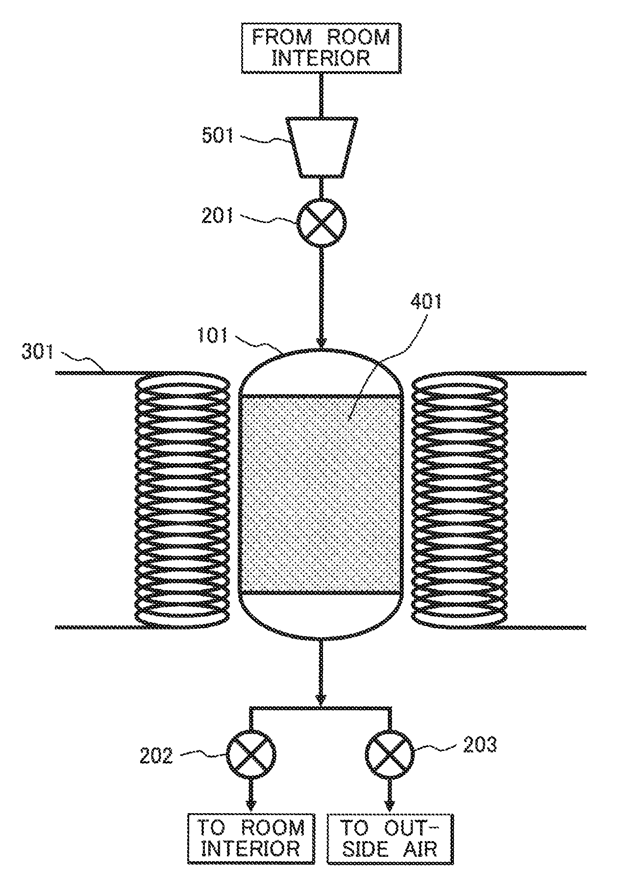
FIG. 1 shows a configuration example for reducing a CO.sub.2 concentration in indoor air by a fixed-bed method using a CO.sub.2 adsorbent.
A CO.sub.2 concentration reducing device shown in FIG. 1 includes an adsorbent container 101, flow control valves 201 to 203, a magnetic field generating unit for induction heating 301 having coiled conductive wires, mixed particles 401 of a CO.sub.2 adsorbent including a cerium oxide and a magnetic body, and a blower 501. A material of a non-magnetic body or a non-metal such as ceramics or an organic substance is desirably used for the adsorbent container 101.
In a method for operating the device, the processes of adsorption, heating, and cooling are repeated. A CO.sub.2 adsorbent temperature during adsorption is set at 30.degree. C. and the CO.sub.2 adsorbent temperature during desorption is set at 200.degree. C.
Firstly, the flow control valves 201 and 202 are opened and the flow control valve 203 is closed. Indoor air is introduced into the adsorbent container 101 with the blower 501, CO.sub.2 is adsorbed and removed, and a gas from which CO.sub.2 is removed is returned to a room interior.
When CO.sub.2 is desorbed and discharged to the atmosphere after CO.sub.2 is adsorbed sufficiently, the flow control valves 201 and 202 are closed and the flow control valve 203 is opened, the mixed particles 401 are heated by the magnetic field generating unit for induction heating 301, and CO.sub.2 is desorbed and discharged to the atmosphere. Successively, during cooling, the flow control valves 201 and 202 are opened and the flow control valve 203 is closed, indoor air is introduced into the adsorbent container 101 with the blower 501, and the mixed particles 401 are cooled.
Trial Calculation of Power Consumption
An electric power consumed when CO.sub.2 is selectively removed by using a CO.sub.2 adsorbent is calculated on trial by the following method. The power consumption is calculated through the following computational expression. (Power consumption)=(Heat requirement)/(Conversion efficiency from electric power to heat)
A heat requirement is calculated as the sum of a heat applied to the CO.sub.2 adsorbent and a CO.sub.2 desorption heat. Physical property values used for the trial calculation are shown in Table 1.
The energy for reducing a CO.sub.2 concentration derived from the physical property values in the table is 8.1 kJ/g-CO.sub.2.
TABLE-US-00001 TABLE 1 Physical property values in using adsorbent method Items Values Adsorbed CO.sub.2 quantity (mol/kg) 0.3 CO.sub.2 adsorbent specific heat (kJ/kgK) 0.4 CO.sub.2 adsorption heat (kJ/mol) 60 Adsorption temperature (.degree. C.) 30 Desorption temperature (.degree. C.) 200 Conversion efficiency from electric power to 80 heat (%)
COMPARATIVE EXAMPLE 1
An electric power required when a CO.sub.2 concentration is adjusted by ventilation, particularly a power consumption required for cooling, is calculated on trial by the following method.
Firstly, an enthalpy difference between outside air and indoor air is calculated and a quotient obtained by dividing the difference by a performance factor is regarded as a power consumption. Here, the enthalpy of air is calculated on the basis of an air temperature of 25.degree. C. and, with regard to water and water vapor, the enthalpy is calculated on the basis of condensed water of 25.degree. C. The variations of the specific heat and the density of air caused by a CO.sub.2 concentration are regarded as minute and thus disregarded. The outside air is regarded as 30.degree. C., a relative density of 70%, and a CO.sub.2 concentration of 400 ppm and indoor air is regarded as 28.degree. C., a relative humidity of 50%, and a CO.sub.2 concentration of 1,000 ppm.
With regard to each of the gases in the respective states, a CO.sub.2 quantity and an enthalpy per dry air 1 kg are shown in Table 2.
The enthalpy difference is 19.1 kJ and the CO.sub.2 content difference is 0.91 g between the outside air and the indoor air. The performance factor in this cooling is assumed to be 2.0 and an electric power required for reducing a CO.sub.2 concentration by ventilation is calculated through the following expression. (Power consumption)=(Enthalpy difference)/{(CO.sub.2 content difference).times.(Performance factor)}
As a result of the trial calculation through the expression, the electric power required for reducing a CO.sub.2 concentration is 10.5 kJ/g-CO.sub.2
TABLE-US-00002 TABLE 2 Physical properties of outside air and indoor air Items Outside air Indoor air Temperature (.degree. C.) 30 28 Relative humidity (%) 70 50 CO.sub.2 concentration (ppm) 400 1000 CO.sub.2 content (g/Nm.sup.3) 0.79 1.96 Air density (kg/Nm.sup.3) 1.293 1.293 CO.sub.2 content (g/kg-Air) 0.61 1.52 Water vapor quantity (g/kg-Air) 19.0 12.0 Condensed water quantity (g/kg-Air) 0 7.0 Total enthalpy (kJ/kg-Air) 51.8 32.7
Electric powers required for reducing a CO.sub.2 concentration by an adsorbent method and by conventional ventilation are shown in FIG. 2.
From FIG. 2, it is obvious that, in comparison with Comparative Example 1, the CO.sub.2 reduction electric power can be lowered and the electric power is saved by the adsorbent method according to Example 1.
COMPARATIVE EXAMPLE 2
FIG. 3 shows a configuration example for reducing a CO.sub.2 concentration in indoor air by a fixed-bed method using a CO.sub.2 adsorbent.
In FIG. 3, a CO.sub.2 concentration reducing device includes an adsorbent container 101, flow control valves 201 to 203, a CO.sub.2 adsorbent 411 including a cerium oxide, a blower 501, and a heater 601 for heating a gas.
In a method for operating the device, the heater 601 for heating a gas is used instead of the magnetic field generating unit for induction heating 301 in FIG. 1. The others are similar to Example 1.
Trial Calculation of Required Ventilation Quantity
In Comparative Example 2, an air quantity required for heating is calculated on trial by the following method. A heat quantity required for heating an adsorbent is regarded as identical to Example 1 and the heat is regarded as obtained by an enthalpy difference of heated air circulating in the adsorbent between an entrance and an exit. A required air quantity calculated by this method is 60.9 g-Air/g-CO.sub.2.
Table 3 shows the conditions used in the trial calculation of Comparative Example 2.
TABLE-US-00003 TABLE 3 Conditions used for trial calculation in Comparative Example 2 Items Values Constant pressure specific heat of air (kJ/kg K) 1.07 Temperature of heated air at adsorbent entrance 300 (.degree. C.) Temperature of heated air at adsorbent exit 200 (.degree. C.)
FIG. 4 is a graph comparatively showing required ventilation quantities in Comparative Examples 1 and 2 and Example 1.
In comparison with Comparative Example 1 of reducing a CO.sub.2 concentration only by ventilation, the required air quantity is reduced substantially in Comparative Example 2 of using an adsorbent. Moreover, in Example 1 using induction heating, it is obvious that ventilation during heating is unnecessary theoretically and a ventilation quantity can be reduced further.
EXAMPLE 2
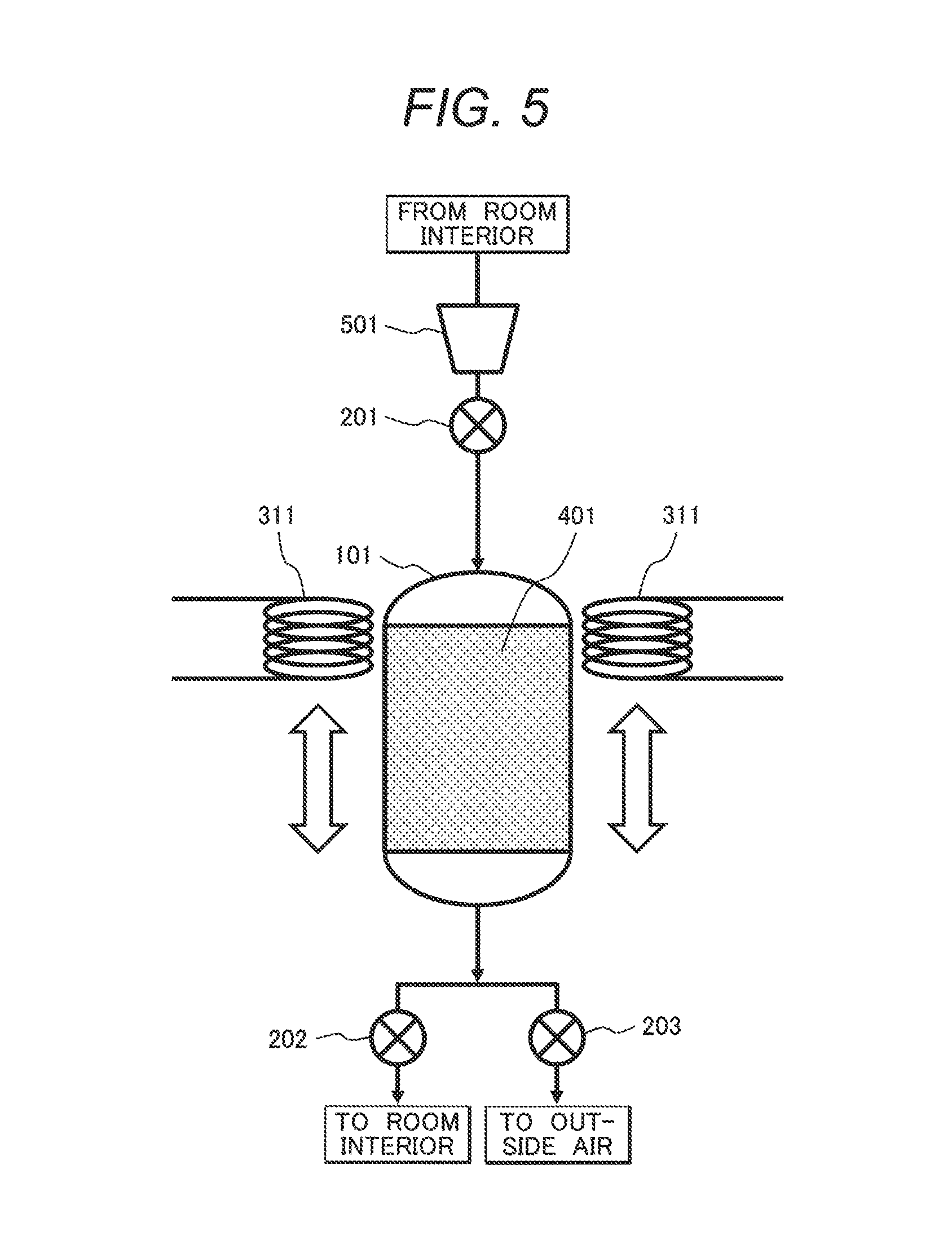
A configuration of arranging a magnetic field generating unit for induction heating so as to be movable in a CO.sub.2 concentration reducing device for reducing a CO.sub.2 concentration in indoor air by a fixed-bed method using a CO.sub.2 adsorbent is shown in FIG. 5.
A CO.sub.2 concentration reducing device shown in FIG. 5 includes an adsorbent container 101, flow control valves 201 to 203, a movable magnetic field generating unit for induction heating 311 having coiled conductive wires, mixed particles 401 of a CO.sub.2 adsorbent including a cerium oxide and a magnetic body, and a blower 501. A material of a non-magnetic body or a non-metal such as ceramics or an organic substance is desirably used for the adsorbent container 101. The magnetic field generating unit for induction heating 311 is movable and can locally heat the magnetic body in the interior of the adsorbent container 101.
In a method for operating the device, the processes of adsorption, heating, and cooling are repeated.
FIGS. 6A to 6C show the state of a heating process by dividing into three stages. The CO.sub.2 absorbent temperature during adsorption is set at 30.degree. C. and the CO.sub.2 absorbent temperature during desorption is set at 200.degree. C.
FIG. 6A is a view schematically showing arrangement at an initial stage of the heating process and a temperature distribution in an adsorbent container according to Example 2. FIG. 6B is a view schematically showing the situation of advancing from the initial stage in FIG. 6A. FIG. 6C is a view schematically showing the situation of advancing further from the stage in FIG. 6B. In each of FIGS. 6A, 6B and 6C, an adsorbent container, a coil schematically representing a magnetic field generating unit for induction heating, and a graph showing the temperature in the adsorbent container are shown side by side.
In an adsorption process as a preliminary stage, the flow control valves 201 and 202 are opened and the flow control valve 203 is closed, those valves being shown in FIG. 5. CO.sub.2 is adsorbed and removed by introducing indoor air into an adsorbent container 101 with a blower 501 and a gas from which CO.sub.2 has been removed is returned to a room interior.
When CO.sub.2 is desorbed and discharged to the atmosphere after CO.sub.2 is adsorbed sufficiently, the flow control valve 202 is closed, the flow control valves 201 and 203 are opened, and mixed particles 401 are heated from the side closer to the blower 501 (entrance side) by a magnetic field generating unit for induction heating 311. The temperature of the relevant site is raised to 200.degree. C. and CO.sub.2 is desorbed. The process is referred to as heating process-1 (FIG. 6A).
Successively, indoor air is circulated in the CO.sub.2 adsorbent container with the blower 501. Heat of the heated adsorbent on the blower side is transported to the exit side by the circulation of the air, the CO.sub.2 adsorbent on the entrance side is cooled, and the CO.sub.2 adsorbent on the exit side is heated. The process is referred to as heating process-2 (FIG. 6B).
Since the CO.sub.2 adsorbent is not heated to 200.degree. C. only by the heat transport, a heat quantity required for raising the temperature to 200.degree. C. is generated by shifting a movable induction heating device to the exit side and applying an alternating current magnetic field. Since the CO.sub.2 adsorbent is heated beforehand by the heat transport caused by air circulation, the consumption of electric power required for heating the CO.sub.2 adsorbent can be reduced more than Example 1. By continuously blowing indoor air during heating and shifting the magnetic field generating unit for induction heating in response to heating, the heated part of the CO.sub.2 adsorbent gradually shifts to the exit side and resultantly CO.sub.2 desorbs. The process is referred to as heating process-3 (FIG. 6C).
By the method, since the CO.sub.2 adsorbent is cooled from the entrance side during CO.sub.2 desorption, the cooling process after CO.sub.2 desorption can be shortened or discarded. When a cooling process is applied, the flow control valves 201 and 202 are opened, the flow control valve 203 is closed, indoor air is introduced into the adsorbent container 101 with the blower 501, and the mixed particles 401 are cooled.
Cases of fixing CO.sub.2 adsorbent particles to a magnetic body are explained hereunder as concrete examples of a shape of a mixed particle (a composite material) of the CO.sub.2 adsorbent and the magnetic body.
FIG. 7 is a schematic perspective view showing an example of a configuration of fixing a CO.sub.2 adsorbent to a linear magnetic body.
In FIG. 7, CO.sub.2 adsorbent particles 702 are fixed to the surface of a straight linear (rod-like) magnetic body 701.
FIG. 8 a schematic perspective view showing an example of a configuration of fixing a CO.sub.2 adsorbent to a spiral magnetic body.
In FIG. 8, CO.sub.2 adsorbent particles 702 are fixed to the surface of a spiral (spring-like) magnetic body 801. By forming such a shape and arranging mixed particles so as to generate a magnetic field in parallel with the center axis of the spiral, when the magnetic body 801 is formed of a metal or the like and has an electric conductivity, electric current is generated in a spiral curve formed by the magnetic body 801 and heat is likely to be generated.
FIG. 9 is a schematic perspective view showing an example of a configuration of fixing a CO.sub.2 adsorbent to an annular magnetic body.
In FIG. 9, CO.sub.2 adsorbent particles 702 are fixed to the surface of an annular magnetic body 901. By forming such a shape and arranging mixed particles so as to generate a magnetic field in parallel with the center axis of the ring, when the magnetic body 901 is formed of a metal or the like and has an electric conductivity, electric current is generated in the ring formed by the magnetic body 901 and heat is likely to be generated.
Here, the dimension of a composite material is not particularly limited and any dimension is acceptable as long as the dimension is efficient as a heating element to generate heat by induction heating or dielectric heating.
In this way, by fixing the particles of a CO.sub.2 adsorbent to a magnetic body acting as a heating element, heat is likely to be transferred to the particles of the CO.sub.2 adsorbent and the desorption efficiency of CO.sub.2 adsorbed in the CO.sub.2 adsorbent to an input energy can be increased.
Meanwhile, although the examples of arranging the coils of the magnetic field generating units for induction heating 301 and 311 over the side faces of the adsorbent containers 101 are shown in FIGS. 1, 5, and 6A to 6C, the position of an magnetic field generating unit for induction heating is not limited to the examples and a configuration of efficiently generating an alternating magnetic field at the position of a magnetic body or the like in the interior of an adsorbent container 101 is desirable. A magnetic field generating unit for induction heating therefore may be arranged so that the center axis of a coil may overlap with an adsorbent container 101 or so that the center axis of a coil may coincide with the center axis of an adsorbent container 101.
Further, in the case of dielectric heating by an alternating electric field, it is desirable to: arrange an electrode pair so as to interpose an adsorbent container 101; and form an electric field so as to penetrate a dielectric body in the interior of the adsorbent container 101 although it is not shown in the figures.
EXPLANATION OF REFERENCE NUMERALS
101: Adsorbent container,
201, 202, 203: Flow control valve,
301, 311: Magnetic field generating unit for induction heating,
401: Mixed particles of CO.sub.2 adsorbent and magnetic body,
411: CO.sub.2 adsorbent,
501: Blower,
601: Heater.
* * * * *
D00000
D00001
D00002
D00003
D00004
D00005
D00006
D00007
D00008
D00009
XML
uspto.report is an independent third-party trademark research tool that is not affiliated, endorsed, or sponsored by the United States Patent and Trademark Office (USPTO) or any other governmental organization. The information provided by uspto.report is based on publicly available data at the time of writing and is intended for informational purposes only.
While we strive to provide accurate and up-to-date information, we do not guarantee the accuracy, completeness, reliability, or suitability of the information displayed on this site. The use of this site is at your own risk. Any reliance you place on such information is therefore strictly at your own risk.
All official trademark data, including owner information, should be verified by visiting the official USPTO website at www.uspto.gov. This site is not intended to replace professional legal advice and should not be used as a substitute for consulting with a legal professional who is knowledgeable about trademark law.