Tissue shaping device
Mathis , et al. Oc
U.S. patent number 10,456,258 [Application Number 15/261,628] was granted by the patent office on 2019-10-29 for tissue shaping device. This patent grant is currently assigned to Cardiac Dimensions Pty. Ltd.. The grantee listed for this patent is Cardiac Dimensions Pty. Ltd.. Invention is credited to Cruz Beeson, Leonard Kowalsky, Mark L. Mathis, David G. Reuter.


| United States Patent | 10,456,258 |
| Mathis , et al. | October 29, 2019 |
Tissue shaping device
Abstract
An anchor anchors a therapeutic device having an elongated body within a body lumen. The anchor includes a fixation member carried on the device which is adjustable from a first configuration that permits placement of the device in the body lumen to a second configuration that anchors the device within the body lumen. The anchor further includes a lock that locks the fixation member in the second configuration. The fixation member may be locked in any one of a plurality of intermediate points between the first configuration and a maximum second configuration.
| Inventors: | Mathis; Mark L. (Fremont, CA), Kowalsky; Leonard (Bothell, WA), Reuter; David G. (Bothell, WA), Beeson; Cruz (Chico, CA) | ||||||||||
|---|---|---|---|---|---|---|---|---|---|---|---|
| Applicant: |
|
||||||||||
| Assignee: | Cardiac Dimensions Pty. Ltd.
(Kirkland, WA) |
||||||||||
| Family ID: | 29399956 | ||||||||||
| Appl. No.: | 15/261,628 | ||||||||||
| Filed: | September 9, 2016 |
Prior Publication Data
| Document Identifier | Publication Date | |
|---|---|---|
| US 20160374810 A1 | Dec 29, 2016 | |
Related U.S. Patent Documents
| Application Number | Filing Date | Patent Number | Issue Date | ||
|---|---|---|---|---|---|
| 10994153 | Nov 19, 2004 | 9474608 | |||
| 10142637 | Nov 30, 2004 | 6824562 | |||
| Current U.S. Class: | 1/1 |
| Current CPC Class: | A61F 2/2466 (20130101); A61F 2/2451 (20130101); A61F 2002/91591 (20130101); A61F 2230/0023 (20130101); A61F 2250/0012 (20130101); A61F 2250/0086 (20130101); A61F 2310/00023 (20130101); A61F 2210/0014 (20130101); A61F 2310/00017 (20130101); A61F 2250/0008 (20130101); A61F 2250/0004 (20130101); A61F 2220/0091 (20130101) |
| Current International Class: | A61F 2/24 (20060101); A61F 2/915 (20130101) |
References Cited [Referenced By]
U.S. Patent Documents
| 3620212 | November 1971 | Fannon, Jr. et al. |
| 3786806 | January 1974 | Johnson et al. |
| 3890977 | June 1975 | Wilson |
| 3974526 | August 1976 | Dardik et al. |
| 3995623 | December 1976 | Blake et al. |
| 4055861 | November 1977 | Carpentier et al. |
| 4164046 | August 1979 | Cooley |
| 4485816 | December 1984 | Krumme |
| 4550870 | November 1985 | Krumme et al. |
| 4588395 | May 1986 | Lemelson |
| 4830023 | May 1989 | de Toledo et al. |
| 5061277 | October 1991 | Carpentier et al. |
| 5099838 | March 1992 | Bardy |
| 5104404 | April 1992 | Wolff |
| 5197978 | March 1993 | Hess |
| 5250071 | October 1993 | Palermo |
| 5261916 | November 1993 | Engelson |
| 5265601 | November 1993 | Mehra |
| 5344426 | September 1994 | Lau et al. |
| 5350420 | September 1994 | Cosgrove et al. |
| 5411549 | May 1995 | Peters |
| 5433727 | July 1995 | Sideris |
| 5441515 | August 1995 | Khosravi et al. |
| 5449373 | September 1995 | Pinchasik et al. |
| 5454365 | October 1995 | Bonutti |
| 5458615 | October 1995 | Klemm et al. |
| 5474557 | December 1995 | Mai |
| 5507295 | April 1996 | Skidmore |
| 5507802 | April 1996 | Imran |
| 5514161 | May 1996 | Limousin |
| 5554177 | September 1996 | Kieval et al. |
| 5562698 | October 1996 | Parker |
| 5575818 | November 1996 | Pinchuk |
| 5584867 | December 1996 | Limousin et al. |
| 5601600 | February 1997 | Ton |
| 5617854 | April 1997 | Munsif |
| 5662703 | September 1997 | Yurek et al. |
| 5676671 | October 1997 | Inoue |
| 5733325 | March 1998 | Robinson et al. |
| 5733328 | March 1998 | Fordenbacher |
| 5741297 | April 1998 | Simon |
| 5752969 | May 1998 | Cunci et al. |
| 5800519 | September 1998 | Sandock |
| 5824071 | October 1998 | Nelson et al. |
| 5836882 | November 1998 | Frazin |
| 5871501 | February 1999 | Leschinsky et al. |
| 5891193 | April 1999 | Robinson et al. |
| 5895391 | April 1999 | Farnholtz |
| 5899882 | May 1999 | Waksman et al. |
| 5908404 | June 1999 | Elliot |
| 5928258 | July 1999 | Khan et al. |
| 5935161 | August 1999 | Robinson et al. |
| 5954761 | September 1999 | Machek et al. |
| 5961545 | October 1999 | Lentz et al. |
| 5978705 | November 1999 | KenKnight et al. |
| 5984944 | November 1999 | Forber |
| 6001118 | December 1999 | Daniel et al. |
| 6007519 | December 1999 | Rosselli |
| 6015402 | January 2000 | Sahota |
| 6022371 | February 2000 | Killion |
| 6027517 | February 2000 | Crocker et al. |
| 6045497 | April 2000 | Schweich, Jr. et al. |
| 6053900 | April 2000 | Brown et al. |
| 6056775 | May 2000 | Borghi et al. |
| 6077295 | June 2000 | Limon et al. |
| 6077297 | June 2000 | Robinson et al. |
| 6080182 | June 2000 | Shaw et al. |
| 6086611 | July 2000 | Duffy et al. |
| 6096064 | August 2000 | Routh |
| 6099549 | August 2000 | Bosma et al. |
| 6099552 | August 2000 | Adams |
| 6129755 | October 2000 | Mathis et al. |
| 6159220 | December 2000 | Gobron et al. |
| 6162168 | December 2000 | Schweich, Jr. et al. |
| 6171320 | January 2001 | Monassevitch |
| 6183512 | February 2001 | Howanec et al. |
| 6190406 | February 2001 | Duerig et al. |
| 6200336 | March 2001 | Pavcnik et al. |
| 6210432 | April 2001 | Solem et al. |
| 6228098 | May 2001 | Kayan et al. |
| 6241757 | June 2001 | An et al. |
| 6254628 | July 2001 | Wallace et al. |
| 6267783 | July 2001 | Letendre et al. |
| 6275730 | August 2001 | KenKnight et al. |
| 6306141 | October 2001 | Jervis |
| 6312446 | November 2001 | Huebsch et al. |
| 6334864 | January 2002 | Amplatz et al. |
| 6342067 | January 2002 | Mathis et al. |
| 6345198 | February 2002 | Mouchawar et al. |
| 6352553 | March 2002 | van der Burg et al. |
| 6352561 | March 2002 | Leopold et al. |
| 6358195 | March 2002 | Green et al. |
| 6368345 | April 2002 | Dehdashtian et al. |
| 6395017 | May 2002 | Dwyer et al. |
| 6402781 | June 2002 | Langberg et al. |
| 6409750 | June 2002 | Hyodoh et al. |
| 6419696 | July 2002 | Ortiz et al. |
| 6442427 | August 2002 | Boute et al. |
| 6464720 | October 2002 | Boatman et al. |
| 6478776 | November 2002 | Rosenman et al. |
| 6503271 | January 2003 | Duerig et al. |
| 6537314 | March 2003 | Langberg et al. |
| 6556873 | April 2003 | Smits |
| 6562066 | May 2003 | Martin |
| 6562067 | May 2003 | Mathis |
| 6569198 | May 2003 | Wilson et al. |
| 6589208 | July 2003 | Ewers et al. |
| 6599314 | July 2003 | Mathis et al. |
| 6602288 | August 2003 | Cosgrove et al. |
| 6602289 | August 2003 | Colvin et al. |
| 6623521 | September 2003 | Steinke et al. |
| 6626899 | September 2003 | Houser et al. |
| 6629534 | October 2003 | St. Goar et al. |
| 6629994 | October 2003 | Gomez et al. |
| 6643546 | November 2003 | Mathis et al. |
| 6648881 | November 2003 | KenKnight et al. |
| 6652538 | November 2003 | Kayan et al. |
| 6656221 | December 2003 | Taylor et al. |
| 6676702 | January 2004 | Mathis |
| 6689164 | February 2004 | Seguin |
| 6709425 | March 2004 | Gambale et al. |
| 6716158 | April 2004 | Raman et al. |
| 6718985 | April 2004 | Hlavka et al. |
| 6721598 | April 2004 | Helland et al. |
| 6723038 | April 2004 | Schroeder et al. |
| 6733521 | May 2004 | Chobotov et al. |
| 6743219 | June 2004 | Dwyer et al. |
| 6764510 | July 2004 | Vidlund et al. |
| 6773446 | August 2004 | Dwyer et al. |
| 6776784 | August 2004 | Ginn |
| 6790231 | September 2004 | Liddicoat et al. |
| 6793673 | September 2004 | Kowalsky et al. |
| 6797001 | September 2004 | Mathis et al. |
| 6798231 | September 2004 | Iwasaki et al. |
| 6800090 | October 2004 | Alferness et al. |
| 6805128 | October 2004 | Pless et al. |
| 6810882 | November 2004 | Langberg et al. |
| 6821297 | November 2004 | Snyders |
| 6824562 | November 2004 | Mathis et al. |
| 6827690 | December 2004 | Bardy |
| 6881220 | April 2005 | Edwin et al. |
| 6890353 | May 2005 | Cohn et al. |
| 6899734 | May 2005 | Castro et al. |
| 6908478 | June 2005 | Alferness et al. |
| 6908482 | June 2005 | McCarthy et al. |
| 6926690 | August 2005 | Renati |
| 6935404 | August 2005 | Duerig et al. |
| 6949122 | September 2005 | Adams et al. |
| 6955689 | October 2005 | Ryan et al. |
| 6960229 | November 2005 | Mathis et al. |
| 6964683 | November 2005 | Kowalsky et al. |
| 6966926 | November 2005 | Mathis |
| 6976995 | December 2005 | Mathis et al. |
| 7004958 | February 2006 | Adams et al. |
| 7152605 | December 2006 | Khairkhahan et al. |
| 7175653 | February 2007 | Gaber |
| 7179282 | February 2007 | Alferness et al. |
| 7270676 | September 2007 | Alferness et al. |
| 7309354 | December 2007 | Mathis et al. |
| 7311729 | December 2007 | Mathis et al. |
| 7316708 | January 2008 | Gordon et al. |
| 7364588 | April 2008 | Mathis et al. |
| 7452375 | November 2008 | Mathis et al. |
| 7503931 | March 2009 | Kowalsky et al. |
| 7591826 | September 2009 | Alferness et al. |
| 7608102 | October 2009 | Adams et al. |
| 7635387 | December 2009 | Reuter et al. |
| 7674287 | March 2010 | Alferness et al. |
| 7758639 | July 2010 | Mathis |
| 7814635 | October 2010 | Gordon |
| 7828841 | November 2010 | Mathis et al. |
| 7828842 | November 2010 | Nieminen et al. |
| 7828843 | November 2010 | Alferness et al. |
| 7837728 | November 2010 | Nieminen et al. |
| 7837729 | November 2010 | Gordon et al. |
| 7887582 | February 2011 | Mathis et al. |
| 8006594 | August 2011 | Hayner et al. |
| 8062358 | November 2011 | Mathis et al. |
| 8075608 | December 2011 | Gordon et al. |
| 8172898 | May 2012 | Alferness et al. |
| 8182529 | May 2012 | Gordon et al. |
| 8439971 | May 2013 | Reuter et al. |
| 8974525 | March 2015 | Nieminen et al. |
| 9320600 | April 2016 | Nieminen et al. |
| 9408695 | August 2016 | Mathis et al. |
| 9474608 | October 2016 | Mathis et al. |
| 9526616 | December 2016 | Nieminen |
| 2001/0018611 | August 2001 | Solem et al. |
| 2001/0041899 | November 2001 | Foster |
| 2001/0044568 | November 2001 | Langberg et al. |
| 2001/0049558 | December 2001 | Liddicoat et al. |
| 2002/0016628 | February 2002 | Langberg et al. |
| 2002/0042621 | April 2002 | Liddicoat et al. |
| 2002/0042651 | April 2002 | Liddicoat et al. |
| 2002/0049468 | April 2002 | Streeter et al. |
| 2002/0055774 | May 2002 | Liddicoat |
| 2002/0065554 | May 2002 | Streeter |
| 2002/0095167 | July 2002 | Liddicoat et al. |
| 2002/0138044 | September 2002 | Streeter et al. |
| 2002/0151961 | October 2002 | Lashinski et al. |
| 2002/0156526 | October 2002 | Hlavka et al. |
| 2002/0161377 | October 2002 | Rabkin et al. |
| 2002/0161393 | October 2002 | Demond et al. |
| 2002/0183837 | December 2002 | Streeter et al. |
| 2002/0183838 | December 2002 | Liddicoat et al. |
| 2002/0183841 | December 2002 | Cohn et al. |
| 2002/0188170 | December 2002 | Santamore et al. |
| 2002/0193827 | December 2002 | McGuckin et al. |
| 2003/0018358 | January 2003 | Saadat |
| 2003/0040771 | February 2003 | Hyodoh et al. |
| 2003/0069636 | April 2003 | Solem et al. |
| 2003/0078465 | April 2003 | Pai et al. |
| 2003/0078654 | April 2003 | Taylor et al. |
| 2003/0083613 | May 2003 | Schaer |
| 2003/0088305 | May 2003 | Van Schie et al. |
| 2003/0093148 | May 2003 | Bolling et al. |
| 2003/0130730 | July 2003 | Cohn et al. |
| 2004/0019377 | January 2004 | Taylor et al. |
| 2004/0039443 | February 2004 | Solem et al. |
| 2004/0073302 | April 2004 | Rourke et al. |
| 2004/0102840 | May 2004 | Solem et al. |
| 2004/0133220 | July 2004 | Lashinski et al. |
| 2004/0133240 | July 2004 | Adams et al. |
| 2004/0153147 | August 2004 | Mathis |
| 2004/0158321 | August 2004 | Reuter et al. |
| 2004/0176840 | September 2004 | Langberg |
| 2004/0193260 | September 2004 | Alferness et al. |
| 2004/0220654 | November 2004 | Mathis et al. |
| 2004/0220657 | November 2004 | Nieminen et al. |
| 2004/0260342 | December 2004 | Vargas et al. |
| 2005/0004667 | January 2005 | Swinford et al. |
| 2005/0027351 | February 2005 | Reuter et al. |
| 2005/0033419 | February 2005 | Alferness et al. |
| 2005/0060030 | March 2005 | Lashinski et al. |
| 2005/0096740 | May 2005 | Langberg et al. |
| 2005/0137449 | June 2005 | Nieminen et al. |
| 2005/0137450 | June 2005 | Aronson et al. |
| 2005/0137451 | June 2005 | Gordon et al. |
| 2005/0149182 | July 2005 | Alferness et al. |
| 2005/0197692 | September 2005 | Pai et al. |
| 2005/0197693 | September 2005 | Pai et al. |
| 2005/0197694 | September 2005 | Pai et al. |
| 2005/0209690 | September 2005 | Mathis et al. |
| 2005/0216077 | September 2005 | Mathis et al. |
| 2005/0261704 | November 2005 | Mathis |
| 2005/0272969 | December 2005 | Alferness et al. |
| 2006/0030882 | February 2006 | Adams et al. |
| 2006/0041305 | February 2006 | Lauterjung |
| 2006/0116758 | June 2006 | Swinford et al. |
| 2006/0142854 | June 2006 | Alferness et al. |
| 2006/0161169 | July 2006 | Nieminen et al. |
| 2006/0167544 | July 2006 | Nieminen et al. |
| 2006/0271174 | November 2006 | Nieminen et al. |
| 2006/0276891 | December 2006 | Nieminen et al. |
| 2007/0066879 | March 2007 | Mathis et al. |
| 2007/0239270 | October 2007 | Mathis et al. |
| 2008/0015407 | January 2008 | Mathis et al. |
| 2008/0015679 | January 2008 | Mathis et al. |
| 2008/0015680 | January 2008 | Mathis et al. |
| 2010/0280602 | November 2010 | Mathis |
| 2011/0066234 | March 2011 | Gordon et al. |
| 2011/0106117 | May 2011 | Mathis et al. |
| 2011/0308367 | December 2011 | Hayner et al. |
| 2012/0123532 | May 2012 | Mathis |
| 2012/0197389 | August 2012 | Alferness et al. |
| 2016/0374809 | December 2016 | Mathis et al. |
| 2017/0189185 | July 2017 | Nieminen et al. |
| 2017/0296341 | October 2017 | Nieminen et al. |
| 2018/0243091 | August 2018 | Nieminen et al. |
| 2018/0243092 | August 2018 | Mathis et al. |
| 0893133 | Jan 1999 | EP | |||
| 0903110 | Mar 1999 | EP | |||
| 0968688 | Jan 2000 | EP | |||
| 1050274 | Nov 2000 | EP | |||
| 1095634 | May 2001 | EP | |||
| 1177779 | Feb 2002 | EP | |||
| 2181670 | May 2010 | EP | |||
| 0741604 | Dec 1955 | GB | |||
| 2754067 | Mar 1998 | JP | |||
| 2000-308652 | Nov 2000 | JP | |||
| 2001-503291 | Mar 2001 | JP | |||
| 2003-503101 | Jan 2003 | JP | |||
| 2003-521310 | Jul 2003 | JP | |||
| 9902455 | Dec 2000 | SE | |||
| WO98/56435 | Dec 1998 | WO | |||
| WO00/44313 | Aug 2000 | WO | |||
| WO00/60995 | Oct 2000 | WO | |||
| WO00/74603 | Dec 2000 | WO | |||
| WO01/00111 | Jan 2001 | WO | |||
| WO01/19292 | Mar 2001 | WO | |||
| WO01/50985 | Jul 2001 | WO | |||
| WO01/54618 | Aug 2001 | WO | |||
| WO01/87180 | Nov 2001 | WO | |||
| WO02/00099 | Jan 2002 | WO | |||
| WO02/01999 | Jan 2002 | WO | |||
| WO02/05888 | Jan 2002 | WO | |||
| WO02/19951 | Mar 2002 | WO | |||
| WO02/34118 | May 2002 | WO | |||
| WO02/47539 | Jun 2002 | WO | |||
| WO02/053206 | Jul 2002 | WO | |||
| WO02/060352 | Aug 2002 | WO | |||
| WO02/062263 | Aug 2002 | WO | |||
| WO02/062270 | Aug 2002 | WO | |||
| WO02/062408 | Aug 2002 | WO | |||
| WO02/076284 | Oct 2002 | WO | |||
| WO02/078576 | Oct 2002 | WO | |||
| WO02/096275 | Dec 2002 | WO | |||
| WO03/015611 | Feb 2003 | WO | |||
| WO03/037171 | May 2003 | WO | |||
| WO03/049647 | Jun 2003 | WO | |||
| WO03/049648 | Jun 2003 | WO | |||
| WO03/055417 | Jul 2003 | WO | |||
| WO03/059198 | Jul 2003 | WO | |||
| WO03/063735 | Aug 2003 | WO | |||
Other References
|
El-Maasarany et al.; The coronary sinus conduit function: Anatomical study (relationship to adjacent structures); http://europace.oxfordjournals.org/cge/content/full/7/5/475. (accessed Sep. 9, 2008). cited by applicant . Gray, H. Anatomy of the Human Body. The Systemic Veins. Philadelphia: Lea & Febiger, 1918; Bartleby.com. 2000. Available at www.bartleby.com/107/. Accessed Jun. 7, 2006. cited by applicant . Heartsite.com. Echocardiogram, 1999; p. 1-4. A.S.M. Systems Inc. Available at: http://www.heartsite.com/html/echocardiogram.html. Accessed Jul. 1, 2005. cited by applicant . Papageorgiou, P., et al. Coronary Sinus Pacing Prevents Induction of Atrial Fibrillation. Circulation. Sep. 16, 1997; 96(6): 1893-1898. cited by applicant . Pelton et al. Medical uses of nitinol; Material Science Forum; vols. 327-328; pp. 63-70; 2000 (held in Kanazawa, Japan, May 1999). cited by applicant . Pijls et al.; Measurement of fractional flow reserve to assess the functional severity of coronary-artery stenoses; The New England J. of Med.; vol. 334; No. 26; pp. 1703-1708; Jun. 27, 1996. cited by applicant . Pai, Suresh; U.S. Appl. No. 60/329,694 entitled "Percutaneous cardiac support structures and deployment means," filed Oct. 16, 2001. cited by applicant . Yamanouchi, et al.; Activation Mapping from the coronary sinus may be limited by anatomic variations; vol. 21 pp. 2522-2526; Nov. 1998. cited by applicant . Nieminen et al.; U.S. Appl. No. 15/136,739 entitled "Tissue shaping device," filed Apr. 22, 2016. cited by applicant . Mathis et al.; U.S. Appl. No. 15/230,060 entitled "Fixed anchor and pull mitral device and method," filed Aug. 5, 2016. cited by applicant . Mathis et al.; U.S. Appl. No. 15/230,093 entitled "Fixed anchor and pull mitral valve device and method," filed Aug. 5, 2016. cited by applicant . Mathis et al.; U.S. Appl. No. 15/261,594 entitled "Tissue shaping device," filed Sep. 9, 2016. cited by applicant . Mathis et al.; U.S. Appl. No. 15/261,549 entitled "Tissue shaping device," filed Sep. 9, 2016. cited by applicant . Mathis et al.; U.S. Appl. No. 15/261,572 entitled "Tissue shaping device," filed Sep. 9, 2016. cited by applicant . Nieminen et al.; U.S. Appl. No. 15/368,467 entitled "Mitral valve annuloplasty device with twisted anchor," filed Dec. 2, 2016. cited by applicant . Wypych; U.S. Appl. No. 15/453,734 entitled "Methods and devices for reducing paravalvular leakage," filed Mar. 8, 2017. cited by applicant. |
Primary Examiner: Wolf; Megan Y
Attorney, Agent or Firm: Shay Glenn LLP
Parent Case Text
CROSS REFERENCE TO RELATED APPLICATIONS
This application is a continuation of U.S. patent application Ser. No. 10/994,153, filed Nov. 19, 2004, now U.S. Pat. No. 9,474,608, which is a divisional of U.S. application Ser. No. 10/142,637, filed May 8, 2002, now U.S. Pat. No. 6,824,562. These applications are incorporated herein by reference in their entirety.
Claims
What is claimed is:
1. A method of performing mitral valve annuloplasty on a patient's heart comprising: percutaneously delivering a mitral valve device to a coronary sinus in a collapsed delivery configuration within a catheter, the mitral valve device comprising a first expandable anchor, a second expandable anchor, and an elongate body extending therebetween, the elongate body defining a longitudinal axis of the mitral valve device; deploying the first expandable anchor from the catheter; expanding the first expandable anchor in the coronary sinus; anchoring the first expandable anchor in an anchored configuration in the coronary sinus, wherein in the anchored configuration the first expandable anchor comprises a flexible elongate member and a securing member for securing a first and second end of the flexible elongate member therein at a distal end of the securing member, the securing member generally aligned with the elongate body along the longitudinal axis, a first segment of the flexible elongate member extending from a distal end of the first expandable anchor to a proximal end of the first expandable anchor to engage the elongate body proximal a distal end of the elongate body, and a second segment of the flexible elongate member extending from where the first segment engages the elongate body to the distal end of the first expandable anchor, the first segment crossing the second segment between the distal and proximal ends of the first expandable anchor; and anchoring the second expandable anchor in the coronary sinus.
2. The method of claim 1, wherein expanding the first expandable anchor comprises allowing the first expandable anchor to self-expand, and wherein deploying the first expandable anchor from the catheter causes the first expandable anchor to self-expand.
3. The method of claim 2, wherein anchoring the first expandable anchor in the anchored configuration comprises locking the first expandable anchor in the anchored configuration.
4. The method of claim 1, wherein anchoring the first expandable anchor in the anchored configuration comprises locking the first expandable anchor in the anchored configuration.
5. The method of claim 4, wherein engagement of the first and second segments of the flexible elongate member to the elongate body comprises a loop in the flexible elongate member around the elongate body, and wherein locking the first expandable anchor in the anchored configuration comprises moving the loop from a first side of a lock element to a second side of the lock element.
6. The method of claim 5, wherein locking the first expandable anchor in the anchored configuration comprises moving the loop from a proximal side of the lock element to a distal side of the lock element.
7. The method of claim 6, wherein moving the loop comprises applying a distally directed force on the first expandable anchor with the catheter.
8. The method of claim 5, wherein expanding the first expandable anchor comprises causing the first expandable anchor to self-expand by deploying the first expandable anchor from the catheter, wherein self-expansion of the first expandable anchor causes the loop to move distally.
9. The method of claim 1, wherein in the collapsed delivery configuration, a location where the first segment crosses the second segment is at a first axial position along the longitudinal axis relative to the securing member, and the location is at a second axial position when the first expandable anchor is in the anchored configuration.
10. The method of claim 9, wherein deploying the first expandable anchor causes the first expandable anchor to self-expand from the catheter, and wherein causing the first expandable anchor to self-expand causes the location to move away from the first axial position.
11. The method of claim 10, wherein causing the first expandable anchor to self-expand causes the location to move distally from the first axial position.
12. The method of claim 11, wherein causing the first expandable anchor to self-expand further causes the location to move radially outward relative to the securing member.
13. The method of claim 9, wherein the first axial position is proximal to the second axial position.
14. The method of claim 1, further comprising recapturing an anchor.
15. The method of claim 14, wherein recapturing an anchor comprises recapturing the first expandable anchor subsequent to expanding the first expandable anchor.
16. The method of claim 15, wherein recapturing the first expandable anchor comprises applying a distally directed force with the catheter on proximal portions of the first and second segments of the flexible elongate member to collapse the proximal portions radially inward toward the securing member and recapture the first expandable anchor within the catheter.
17. The method of claim 15, wherein recapturing the first expandable anchor can occur after locking the first expandable anchor in the anchored configuration.
18. The method of claim 14, wherein recapturing an anchor comprises recapturing the second expandable anchor.
Description
FIELD OF THE INVENTION
The present invention generally relates to an anchor for use with a device which requires anchoring in a body lumen. The present invention more particularly relates to a mitral valve annulus device and assembly wherein the device is deployed and anchored in the coronary sinus of a heart adjacent the mitral valve annulus to reshape the mitral valve annulus.
BACKGROUND OF THE INVENTION
The human heart generally includes four valves. Of these valves, a most critical one is known as the mitral valve. The mitral valve is located in the left atrial ventricular opening between the left atrium and left ventricle. The mitral valve is intended to prevent regurgitation of blood from the left ventricle into the left atrium when the left ventricle contracts. In preventing blood regurgitation the mitral valve must be able to withstand considerable back pressure as the left ventricle contracts.
The valve cusps of the mitral valve are anchored to muscular wall of the heart by delicate but strong fibrous cords in order to support the cusps during left ventricular contraction. In a healthy mitral valve, the geometry of the mitral valve ensures that the cusps overlie each other to preclude regurgitation of the blood during left ventricular contraction.
The normal functioning of the mitral valve in preventing regurgitation can be impaired by dilated cardiomyopathy caused by disease or certain natural defects. For example, certain diseases may cause dilation of the mitral valve annulus. This can result in deformation of the mitral valve geometry to cause ineffective closure of the mitral valve during left ventricular contraction. Such ineffective closure results in leakage through the mitral valve and regurgitation. Diseases such as bacterial inflammations of the heart or heart failure can cause the aforementioned distortion or dilation of the mitral valve annulus. Needless to say, mitral valve regurgitation must not go uncorrected.
One method of repairing a mitral valve having impaired function is to completely replace the valve. This method has been found to be particularly suitable for replacing a mitral valve when one of the cusps has been severely damaged or deformed. While the replacement of the entire valve eliminates the immediate problem associated with a dilated mitral valve annulus, presently available prosthetic heart valves do not possess the same durability as natural heart valves.
Various other surgical procedures have been developed to correct the deformation of the mitral valve annulus and thus retain the intact natural heart valve function. These surgical techniques involve repairing the shape of the dilated or deformed valve annulus. Such techniques, generally known as annuloplasty, require surgically restricting the valve annulus to minimize dilation. Here, a prosthesis is typically sutured about the base of the valve leaflets to reshape the valve annulus and restrict the movement of the valve annulus during the opening and closing of the mitral valve.
Many different types of prostheses have been developed for use in such surgery. In general, prostheses are annular or partially annular shaped members which fit about the base of the valve annulus. The annular or partially annular shaped members may be formed from a rigid material, such as a metal, or from a flexible material.
While the prior art methods mentioned above have been able to achieve some success in treating mitral regurgitation, they have not been without problems and potential adverse consequences. For example, these procedures require open heart surgery. Such procedures are expensive, are extremely invasive requiring considerable recovery time, and pose the concomitant mortality risks associated with such procedures. Moreover, such open heart procedures are particularly stressful on patients with a compromised cardiac condition. Given these factors, such procedures are often reserved as a last resort and hence are employed late in the mitral regurgitation progression. Further, the effectiveness of such procedures is difficult to assess during the procedure and may not be known until a much later time. Hence, the ability to make adjustments to or changes in the prostheses to obtain optimum-effectiveness is extremely limited. Later corrections, if made at all, require still another open heart surgery.
An improved therapy to treat mitral regurgitation without resorting to open heart surgery has recently been proposed. This is rendered possible by the realization that the coronary sinus of a heart is near to and at least partially encircles the mitral valve annulus and then extends into a venous system including the great cardiac vein. As used herein, the term "coronary sinus" is meant to refer to not only the coronary sinus itself but in addition, the venous system associated with the coronary sinus including the great cardiac vein. The therapy contemplates the use of a device introduced into the coronary sinus to reshape and advantageously effect the geometry of the mitral valve annulus.
The device includes a resilient member having a cross sectional dimension for being received within the coronary sinus of the heart and a longitudinal dimension having an unstressed arched configuration when placed in the coronary sinus. The device partially encircles and exerts an inward pressure on the mitral valve. The inward pressure constricts the mitral valve annulus, or at least a portion of it, to essentially restore the mitral valve geometry. This promotes effective valve sealing action and eliminates mitral regurgitation.
The device may be implanted in the coronary sinus using only percutaneous techniques similar to the techniques used to implant cardiac leads such as pacemaker leads. One proposed system for implanting the device includes an elongated introducer configured for being releasably coupled to the device. The introducer is preferably flexible to permit it to advance the device into the heart and into the coronary sinus through the coronary sinus ostium. To promote guidance, an elongated sheath is first advanced into the coronary sinus. Then, the device and introducer are moved through a lumen of the sheath until the device is in position within the coronary sinus. Because the device is formed of resilient material, it conforms to the curvatures of the lumen as it is advanced through the sheath. The sheath is then partially retracted to permit the device to assume its unstressed arched configuration. Once the device is properly positioned, the introducer is then decoupled from the device and retracted through the sheath. The procedure is then completed by the retraction of the sheath. As a result, the device is left within the coronary sinus to exert the inward pressure on the mitral valve to restore mitral valve geometry.
The foregoing therapy has many advantages over the traditional open heart surgery approach. Since the device, system and method may be employed in a comparatively noninvasive procedure, mitral valve regurgitation may be treated at an early stage in the mitral regurgitation progression. Further, the device may be placed with relative ease by any minimally invasive cardiologist. Still further, since the heart remains completely intact throughout the procedure, the effectiveness of the procedure may be readily determined. Moreover, should adjustments be deemed desirable, such adjustments may be made during the procedure and before the patient is sent to recovery.
Another approach to treat mitral regurgitation with a device in the coronary sinus is based upon the observation that the application of a localized force against a discrete portion of the mitral valve annulus can terminate mitral regurgitation. This suggests that mitral regurgitation may be localized and nonuniform. Hence, the device applies a force to one or more discrete portions of the atrial wall of the coronary sinus to provide localized mitral valve annulus reshaping instead of generalized reshaping of the mitral valve annulus. Such localized therapy would have all the benefits of the generalized therapy. In addition, a localized therapy device may be easier to implant and adjust.
A still further approach to treat mitral regurgitation from the coronary sinus of the heart contemplates a device having a first anchor configured to be positioned within and fixed to the coronary sinus of the heart adjacent the mitral valve annulus within the heart, a cable fixed to the first anchor and extending proximally from the first anchor within the heart, a second anchor configured to be positioned in and fixed in the heart proximal to the first anchor and arranged to slidingly receive the cable, and a lock that locks the cable on the second anchor. When the first and second anchors are fixed within the heart, the cable may be drawn proximally and locked on the second anchor. The geometry of the mitral valve is thereby effected. This approach provides flexibility in that the second anchor may be positioned and fixed in the coronary sinus or alternatively, the second anchor may be positioned and fixed in the right atrium. This approach further allows adjustments in the cable tension after implant.
A still further alternative for treating mitral regurgitation contemplates a device having a first anchor configured to be positioned within and anchored to the coronary sinus of the heart adjacent the mitral valve annulus within the heart. A second anchor is configured to be positioned within the heart proximal to the first anchor and adjacent the mitral valve annulus within the heart. A connecting member, having a fixed length, is permanently attached to the first and second anchors. As a result, when the first and second anchors are within the heart with the first anchor anchored in the coronary sinus, the second anchor may be displaced proximally to effect the geometry of the mitral valve annulus and released to maintain the effect on the mitral valve geometry. The second anchor may be configured, when deployed, to anchor against distal movement but be movable proximally to permit the second anchor to be displaced proximally within the coronary sinus.
A further device that effects the condition of a mitral valve annulus of a heart also includes an elongated member dimensioned to be placed in the coronary sinus of the heart adjacent the mitral valve annulus. Here, the elongated member is flexible when placed in the heart in a first orientation to position the device in the coronary sinus adjacent the mitral valve annulus and relatively inflexible when rotated into a second orientation after the device is positioned in the coronary sinus adjacent to the mitral valve annulus.
The device thus has a first radius of curvature when in the first orientation and a second and greater radius of curvature when in the second orientation to effect the mitral valve geometry. Once positioned and in the second orientation, the device is anchored against both longitudinal and rotational movement.
Devices, other than those described above may be placed in body lumens other than the coronary sinus for therapeutic effect. All such devices must be anchored against movement when deployed at least for an acute phase until the natural body mechanisms produce sufficient fibrotic tissue about the devices for permanent fixation. While the device anchors must protect against device movement, they must also allow ready deployment to facilitate device implant. However, it is desirable that the anchors also be readily releasable, at least during the acute phase to permit device position adjustment or even device removal if required. All of these factors are especially important for devices implanted in the heart because of the potential need for precise device positioning during implant and the extreme movement of the heart during heartbeats.
SUMMARY OF THE INVENTION
The invention provides an anchor that anchors a device having an elongated body in a body lumen. The anchor includes a fixation member carried on the device, the fixation member being adjustable from a first configuration that permits placement of the device in the body lumen to a second configuration that anchors the device within the body lumen, and a lock that locks the fixation member in the second configuration.
The lock is releasable to release the fixation member from the second configuration to permit the device to be removed from the body lumen. The fixation member may also be deformable to permit the device to be moved within the body lumen.
The fixation member is adjustable from the first configuration to a maximum second configuration. The lock may be configured to lock the fixation member at any one of a plurality of intermediate points between the first configuration and the maximum second configuration.
The fixation member may be elongated and have a first end hingedly coupled to the device body. The fixation member may thus extend along the device body closely spaced to the device body when in the first configuration and be pivoted from the device body to the second configuration to engage and anchor the device in the body lumen.
The anchor may further include a support that renders the fixation member substantially rigid when in the second configuration. The support may be an extension of the fixation member, wherein the fixation member includes a second end opposite the first end and wherein the lock locks the fixation member second end on the device body.
The fixation member may include a second end opposite the first end. The support may include a support member having a first end hingedly coupled to the fixation member second end and a second end opposite the support member first end. The lock may lock the support member second end on the device body. The support member second end may be slidable along the device body. The anchor may include a plurality of the fixation members and/or a plurality of support members.
The invention further provides a device that effects the condition of a mitral valve annulus of a heart. The device includes an elongated body dimensioned to be placed in the coronary sinus of the heart adjacent the mitral valve annulus. The device further includes a fixation member carried by the device, the fixation member being adjustable from a first configuration that permits placement of the device in the coronary sinus to a second configuration that anchors the device within the coronary sinus, and a lock that locks the fixation member in the second configuration.
The lock is releasable to release the fixation member from the second configuration to permit the device to be moved within the coronary sinus. The fixation member may be deformable to permit the device to be moved within the coronary sinus.
The fixation member may be adjustable from the first configuration to a maximum second configuration and the lock may lock the fixation member at any one of a plurality of intermediate points between the first configuration and the maximum second configuration.
The fixation member is elongated and has a first end hingedly coupled to the device body. The fixation member may extend along the device body closely spaced to the device body when in the first configuration and may be pivoted from the device body when in the second configuration to engage the coronary sinus and anchor the device in the coronary sinus. The device may further include a support that renders the fixation member substantially rigid when in the second configuration. The support may be an extension of the fixation member, wherein the fixation member includes a second end opposite the first end and wherein the lock locks the fixation member second end on the device body. The fixation member second end may be slidable along the device body and the device may include a plurality of the fixation members.
The fixation member may include a second end opposite the first end. The support may be a separate support member having a first end hingedly coupled to the fixation member second end and second end opposite the support member first end. The lock may then lock the support member second end on the device body. The support member second end may be slidable along the device body. The device may include a plurality of the fixation members and support members.
The invention further provides an assembly that effects the condition of a mitral valve annulus of a heart. The assembly includes a mitral valve therapy device dimensioned to be placed in the coronary sinus adjacent the mitral valve annulus. The device includes an elongated body, a fixation member carried by the device, the fixation member being adjustable from a first configuration that permits placement of the device in the coronary sinus to a second configuration that anchors the device within the coronary sinus, and a lock that locks the fixation member in the second configuration. The assembly further includes a flexible catheter having a lumen that receives the device and being dimensioned to be advanced into the coronary sinus to place the device adjacent the coronary sinus.
The assembly may further include an elongated pusher that is received by the lumen of the catheter proximal to the device and that permits the device and the catheter to be moved opposite each other. The assembly may further include a tether receivable by the catheter lumen and engageable with the device to pull the device distally with respect to the catheter. The catheter may be used to transition the fixation member from the first configuration to the second configuration. For example, the fixation member may be elongated and have a first end hingedly coupled to the device body. The fixation member may then extend along the device body when in the first configuration and the fixation member may be pivoted from the device body into the second configuration by distal movement of the catheter with respect to the device to cause the fixation member to engage the coronary sinus and anchor the device in the coronary sinus.
BRIEF DESCRIPTION OF THE DRAWINGS
The features of the present invention which are believed to be novel are set forth with particularity in the appended claims. The invention, together with further aspects and advantages thereof, may best be understood by making reference to the following description taken in conjunction with the accompanying drawings, in the several figures of which like reference numerals identify identical elements, and wherein:
FIG. 1 is a superior view of a human heart with the atria removed;
FIG. 2 is a superior view of a human heart similar to FIG. 1 illustrating a mitral valve therapy device including an anchor embodying the present invention deployed therein along with an assembly embodying the present invention for deploying the device;
FIG. 3 is a side view with portions cut away illustrating a first step in deploying the device anchor of the device of FIG. 2;
FIG. 4 is a side view similar to FIG. 3 illustrating a further step in the deployment of the anchor embodying the present invention;
FIG. 5 is a side view similar to FIG. 3 illustrating a further step in the deployment of the device anchor;
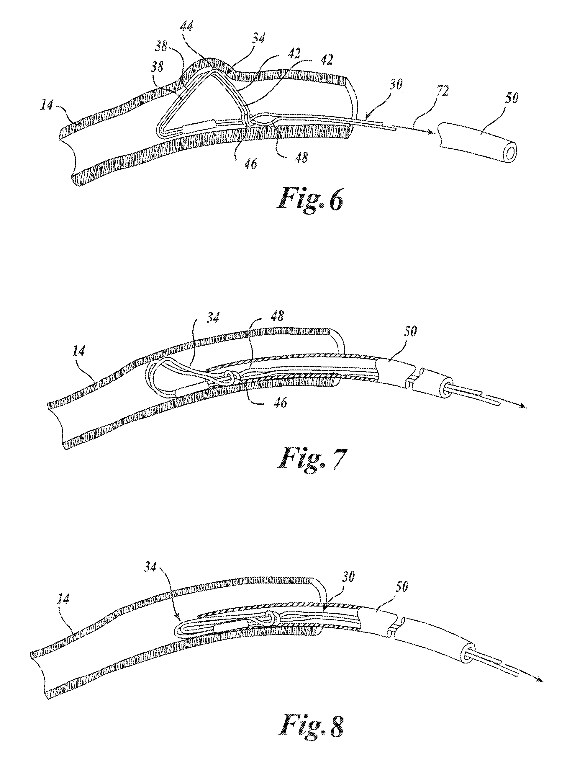
FIG. 6 is a side view similar to FIG. 3 illustrating the deployed device anchor;
FIG. 7 is a side view similar to FIG. 3 illustrating a first step in the removal of the device anchor;
FIG. 8 is a side view similar to FIG. 3 illustrating a final step in the removal of the device anchor;
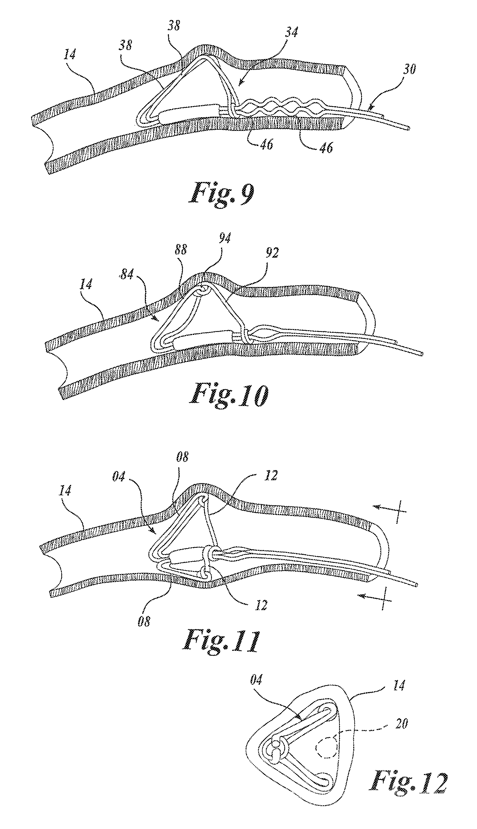
FIG. 9 is a side view similar to FIG. 3 illustrating an alternate embodiment of a deployed device anchor embodying the present invention;
FIG. 10 is a side view similar to FIG. 3 illustrating a further embodiment of a deployed device anchor embodying the present invention;
FIG. 11 is a side view similar to FIG. 3 illustrating a still further embodiment of a deployed device anchor embodying the present invention; and
FIG. 12 is an end view of FIG. 11.
DETAILED DESCRIPTION OF THE INVENTION
Referring now to FIG. 1, it is a superior view of a human heart 10 with the atria removed to expose the mitral valve 12, the coronary sinus 14, the coronary artery 15, and the circumflex artery 17 of the heart 10 to lend a better understanding of the present invention. Also generally shown in FIG. 1 are the pulmonary valve 22, the aortic valve 24, and the tricuspid valve 26 of the heart 10.
The mitral valve 12 includes an anterior cusp 16, a posterior cusp 18 and an annulus 20. The annulus encircles the cusps 16 and 18 and maintains their spacing to provide a complete closure during a left ventricular contraction. As is well known, the coronary sinus 14 partially encircles the mitral valve 12 adjacent to the mitral valve annulus 20. As is also known, the coronary sinus is part of the venous system of the heart and extends along the AV groove between the left atrium and the left ventricle. This places the coronary sinus essentially within the same plane as the mitral valve annulus making the coronary sinus available for placement of the mitral valve therapy device of the present invention therein.
FIG. 2 shows a mitral valve therapy device 30 embodying the present invention shown deployed in the coronary sinus 14 of the heart 10 adjacent the mitral valve annulus 20 for effecting the geometry of the mitral valve annulus. Also shown in FIG. 2 is a deployment system 50 that deploys the device 30 in the coronary sinus 14. The device 30 takes the form of an elongated body 32 which includes a distal anchor 34 embodying the present invention and a proximal anchor 36.
The anchors 34 and 36 are shown in FIG. 2 in their deployed configuration. As will be seen hereinafter, upon deployment of the device 30 in the coronary sinus, the distal anchor 34 is transitioned from a first configuration to a locked second configuration. In the process, it is expanded outwardly to anchor the device in the coronary sinus against both bi-directional longitudinal and rotational movement. The proximal anchor however, when deployed, is configured to permit proximal movement. This allows the device 30 to be tightened within the coronary sinus by proximal pulling of the anchor 36 after the distal anchor 34 is deployed. The device 30 may be formed from Nitinol or stainless steel, for example.
The deployment system 52 illustrated in FIG. 2 includes an elongated catheter 50, an elongated pusher 54, and a tether 56. In deploying the device 30, the tether 56 is first looped about the proximal anchor 36 of the device 30 as illustrated and the device is then loaded into the catheter 50. The tether 56 is then threaded through an internal lumen 58 of the pusher 54 and looped around the proximal anchor 36 of the device 30 as illustrated. The pusher 54 is then advanced along the tether 56 for engaging the device 30 and pushing the device distally down the catheter to a predetermined position at the distal end of the catheter 50. The catheter with the device 30 loaded therein is then fed into the heart and through the coronary sinus ostium 31 into the coronary sinus to place the catheter in a position such that the device 30 is adjacent the mitral valve annulus 20. Thereafter, the device is maintained in a stationary position by the pusher 54 as the catheter 50 is partially withdrawn to expose the distal anchor 34. Once the distal anchor is exposed, it is deployed by the catheter in a manner to be described more particularly with respect to FIGS. 3-6. Once the distal anchor 34 is deployed, the catheter 50 is then retracted proximally of the proximal anchor 36. This exposes the proximal anchor 36 and permits the proximal anchor to self deploy. Once the proximal anchor is deployed, the tether 56 is pulled proximally to move the proximal anchor 36 in a proximal direction for tightening the device within the coronary sinus and to an extent which results in the desired effect on the geometry of the mitral valve annulus 20. During this adjustment process, mitral regurgitation may be monitored and the device adjusted for optimal results. When the device 30 is in its final position within the coronary sinus 14, the pusher 54 and catheter 50 may be removed from the heart. The tether 56 may be permitted to remain in the heart during an acute phase to ascertain the effectiveness of the device 30. Should further adjustment of the device be necessary, the tether 56 may then be used as a guide for guiding the introduction of the catheter 50 back into the heart.
FIGS. 3-6 illustrate the manner in which the distal anchor 34 may be deployed in the coronary sinus 14 for anchoring the device 30. It will be appreciated by those skilled in the art, of course, that the anchor 34 may be utilized in body lumens other than the coronary sinus and with therapeutic devices other than the mitral valve annulus therapy device illustrated in FIG. 2.
In each of FIGS. 3-6 a portion of the coronary sinus has been removed and the pusher has not been illustrated so as to not unduly complicate the figures. FIG. 3 shows the catheter 50 disposed within the coronary sinus 14 with the device 30 and distal anchor within the catheter 50. To that end, the catheter includes a lumen 60 which is dimensioned to receive the device 30 and the distal anchor 34 when the distal anchor 34 is in a first configuration. The distal anchor 34 includes an elongated fixation member 38 which is hingedly coupled to the distal end of the device 30 at a hinge 40. The elongated fixation member thus extends along the body of the device 30. The fixation member includes a support 42 which is an extension of the fixation member 38 and which is hingedly connected to the fixation member 38 at a hinge point 44. The proximal end of the fixation member 38 includes a loop 46 which is looped about the device 30 to permit the loop 46 to slide along the device 30. As will be seen subsequently, the loop 46 forms part of a lock for locking the anchor 34 in a second configuration for anchoring in the coronary sinus.
To complete the anchor, the device 30 includes a resilient enlarged portion 48 over which the loop 46 may slide. Once the loop 46 is located distally of the enlarged portion 48, it will be held by the enlarged portion 48 for locking the device in the second configuration.
FIG. 4 illustrates the anchor 34 after the catheter 50 has been moved proximal to the anchor 34. More specifically, it will be noted that the distal end of the catheter 50 is now proximal to the loop 46 or proximal end of the anchor 34. The shape memory of the anchor has caused the anchor to expand and is now partially transitioned from the first configuration of FIG. 3 to the second and final configuration to be described with reference to FIG. 6 subsequently.
FIG. 5 illustrates the anchor 34 being transitioned from the first configuration to the second configuration. This transition is implemented by the distal end of the catheter 50 pushing the proximal end of the anchor 34 in the distal direction. To maintain the position of the anchor 34 during the transition, the tether 56 is used to hold the device 30 against distal movement.
The particular configuration of the distal anchor 34 in accordance with this embodiment may be more particularly seen in FIG. 5. Here it may be seen that the distal anchor is formed of a wire having a first end secured to the distal end of the device 30, folded back and looped around the device and then back to the distal end of the device. Both ends of the anchor are then crimped by a crimp 70. This configuration results in a pair of fixation members 38 each having a support extension 42. In addition, the fixation members 38 may be formed so as to have a loop configuration to maximize surface contact with the inner wall of the coronary sinus 14. As shown, one of the fixation members 38 crosses the other fixation member 38 at a location between a distal end and a proximal end of the distal anchor 34.
As the catheter 50 is moved distally, it forces the loop 46 of the anchor 34 over the enlarged portion 48 of the device 30 to a point distal to the enlarged portion 48. This locks the loop 46 distally of the enlarged portion 48 for locking the anchor 34 in an enlarged second configuration as illustrated in FIG. 6 to anchor the device 30 within the coronary sinus 14. More specifically, it may be seen that the supports 42 have been pivoted at the hinge 44 relative to the fixation member 38. This allows the fixation members 38 to be supported by the supports 42 and securely locked by the lock of the loop 46 and enlarged portion 48 of the device 30. The fixation members 38 provide broad surface contact with the inner wall of the coronary sinus 14. This provides for anchoring within the coronary sinus of the device 30 against both bi-directional longitudinal and rotational movement. Once the anchor 34 is deployed as illustrated in FIG. 6, the catheter 50 may then be removed as indicated by the arrow 72.
One of the many features of the anchor of the instant invention is that it may be moved within or removed from the body lumen in which it is deployed. More specifically, and making reference to FIG. 6, the anchor 34 may be removed by grabbing the support members 42 and pulling the loop 46 over the resilient enlarged portion 48 of the device 30. When the loop 46 is on the proximal side of the enlarged portion 48, further proximal movement of the loop 46 will fully transition the anchor 34 from the second configuration back to the first configuration for removal within the catheter 50.
Alternatively, by virtue of the support members, the anchor 34 may be formed of deformable material such as stainless steel. Using this to advantage, the anchor 34 may be partially collapsed by the catheter 50 to permit the anchor 34 and hence the device 30 to be moved and repositioned in the coronary sinus after which the resilience of the anchor material returns the anchor to its locked and deployed configuration. The anchor may be collapsed by the catheter 50 as illustrated in FIGS. 7 and 8.
In FIG. 7, it will be noted that the catheter 50, while the device is held stationary by the tether, is moved distally over the enlarged portion 48 and the loop 46. The anchor 34 is now partially collapsed for movement and repositioning. Once repositioned, the catheter may be withdrawn to redeploy the anchor 34 which returns to its second configuration by virtue of its resiliency and shape memory.
As seen in FIG. 8, continued distal movement of the catheter 50 causes the anchor 34 to fully collapse. This allows the anchor 34 to be totally drawn into the catheter 50. Once the anchor 34 is collapsed and within the catheter 50, the device 30 may be removed by removing the catheter with the device therein or by pulling the device proximally through the catheter.
FIGS. 9-12 illustrate alternative embodiments of the anchor of the present invention. These embodiments are once again illustrated in connection with the anchoring of a mitral valve annulus therapy device within the coronary sinus of a heart.
In FIG. 9, the device 30 is shown having a plurality of enlarged portions 46. As a result, a plurality of locks are provided on the device 30 to enable the fixation members to be locked at any one of a plurality of intermediate points between the first configuration and a maximum second configuration illustrated in FIG. 9. This enables the anchor 34 to be sized to a given body lumen.
FIG. 10 shows another anchor 84 embodying the present invention which has a separate fixation member 88 and support member 92. The second or distal end of the fixation member 88 is hingedly coupled to a first or distal end of the support member 92 by a hinged connection 94. The fixation member 88 may have a hoop configuration as the fixation members 38 previously described.
FIGS. 11 and 12 illustrated a still further anchor 104 having a pair of fixation members 108 and corresponding separate support members 112. Here, the fixation members 108 are formed by immediately adjacent anchor wires which, as best seen in FIG. 12, are disposed at an angle to permit a cardiac lead, indicated by the dashed circle 120, to pass through the anchor and thus be within the coronary sinus. Hence, a device having an anchor such as anchor 104 is compatible with the provision of a cardiac lead therewith.
As can thus been seen, the present invention provides a new and improved anchor for anchoring a therapeutic device within a body lumen. The anchor of the present invention, by virtue of the lockable support member, creates mechanical advantage to assist deployment of the anchor. This also increases anchor strength. Because the support members may be of hooped or looped configuration, increased contact area between the anchor and the body lumen can be achieved. In addition, the anchor of the present invention allows deactivation and repositioning of the anchor or therapeutic device incorporating the anchor. Still further, because of the locked support structure, the anchor may be formed of smaller diameter wire, tube wall, or other materials which without the locked support provided by the anchor of the present invention would be unsuitable for this application.
While particular embodiments of the present invention have been shown and described, modifications may be made. It is therefore intended in the appended claims to cover all such changes and modifications which fall within the true spirit and scope of the invention.
* * * * *
References
D00000
D00001
D00002
D00003
D00004
XML
uspto.report is an independent third-party trademark research tool that is not affiliated, endorsed, or sponsored by the United States Patent and Trademark Office (USPTO) or any other governmental organization. The information provided by uspto.report is based on publicly available data at the time of writing and is intended for informational purposes only.
While we strive to provide accurate and up-to-date information, we do not guarantee the accuracy, completeness, reliability, or suitability of the information displayed on this site. The use of this site is at your own risk. Any reliance you place on such information is therefore strictly at your own risk.
All official trademark data, including owner information, should be verified by visiting the official USPTO website at www.uspto.gov. This site is not intended to replace professional legal advice and should not be used as a substitute for consulting with a legal professional who is knowledgeable about trademark law.