Oral care implement
Jimenez , et al. Oc
U.S. patent number 10,455,931 [Application Number 15/539,399] was granted by the patent office on 2019-10-29 for oral care implement. This patent grant is currently assigned to Colgate-Palmolive Company. The grantee listed for this patent is Colgate-Palmolive Company. Invention is credited to Eduardo Jimenez, Joachim Storz, Andreas Wechsler.


| United States Patent | 10,455,931 |
| Jimenez , et al. | October 29, 2019 |
Oral care implement
Abstract
An oral care implement including an elastomeric component that includes a bumper portion that forms a distal-most section of the peripheral surface and a wall portion located along a distal-most section of the perimeter edge and protruding above the front surface. The wall portion may include a first ramped portion, an apex portion, and a second ramped portion. The wall portion may include a plurality of spaced-apart ridges protruding from an outer surface of the bumper portion and an outer surface of the wall portion. An oral care implement is disclosed that includes a soft tissue cleanser having a plurality of protuberances of differing heights.
| Inventors: | Jimenez; Eduardo (Manalapan, NJ), Storz; Joachim (Zell am See, AT), Wechsler; Andreas (Zell am See, AT) | ||||||||||
|---|---|---|---|---|---|---|---|---|---|---|---|
| Applicant: |
|
||||||||||
| Assignee: | Colgate-Palmolive Company (New
York, NY) |
||||||||||
| Family ID: | 52350369 | ||||||||||
| Appl. No.: | 15/539,399 | ||||||||||
| Filed: | December 23, 2014 | ||||||||||
| PCT Filed: | December 23, 2014 | ||||||||||
| PCT No.: | PCT/US2014/072066 | ||||||||||
| 371(c)(1),(2),(4) Date: | June 23, 2017 | ||||||||||
| PCT Pub. No.: | WO2016/105369 | ||||||||||
| PCT Pub. Date: | June 30, 2016 |
Prior Publication Data
| Document Identifier | Publication Date | |
|---|---|---|
| US 20170367473 A1 | Dec 28, 2017 | |
| Current U.S. Class: | 1/1 |
| Current CPC Class: | A46B 9/04 (20130101); A46B 15/0081 (20130101); A46B 2200/1066 (20130101) |
| Current International Class: | A46B 15/00 (20060101); A46B 9/04 (20060101) |
References Cited [Referenced By]
U.S. Patent Documents
| 758764 | May 1904 | MacLeod |
| 846900 | March 1907 | Bloom |
| 1125532 | January 1915 | Himmel |
| 1901230 | March 1933 | Palmer |
| 1924152 | August 1933 | Coney et al. |
| 2161349 | June 1939 | Hadden |
| 2186005 | January 1940 | Casto |
| 2305461 | December 1942 | Spyra |
| D273635 | May 1984 | Stocchi |
| 4517701 | May 1985 | Stanford, Jr. |
| 4958402 | September 1990 | Weihrauch |
| 5144712 | September 1992 | Hansel et al. |
| 5339482 | August 1994 | Desimone et al. |
| 5392483 | February 1995 | Heinzelman et al. |
| 5584690 | December 1996 | Maassarani |
| 5604951 | February 1997 | Shipp |
| 5628082 | May 1997 | Moskovich |
| 5651158 | July 1997 | Halm |
| D390706 | February 1998 | Hohlbein et al. |
| 5735012 | April 1998 | Heinzelman et al. |
| 5746532 | May 1998 | Megill et al. |
| 5758383 | June 1998 | Hohlbein |
| 5781958 | July 1998 | Meessmann et al. |
| 5799353 | September 1998 | Yamamoto et al. |
| 5802656 | September 1998 | Dawson et al. |
| 5839149 | November 1998 | Scheier et al. |
| D404205 | January 1999 | Hohlbein |
| D404206 | January 1999 | Hohlbein |
| 5862559 | January 1999 | Hunter |
| 5863102 | January 1999 | Waguespack et al. |
| 5908038 | June 1999 | Bennett |
| 5915868 | June 1999 | Frazell |
| 5930860 | August 1999 | Shipp |
| 5946758 | September 1999 | Hohlbein et al. |
| 5967152 | October 1999 | Rimkus |
| 5970564 | October 1999 | Inns et al. |
| 5984935 | November 1999 | Budei et al. |
| 5991958 | November 1999 | Hohlbein |
| 6015293 | January 2000 | Rimkus |
| 6032313 | March 2000 | Tsang |
| 6041468 | March 2000 | Chen et al. |
| 6073299 | June 2000 | Hohlbein |
| 6088870 | July 2000 | Hohlbein |
| D429887 | August 2000 | Hohlbein et al. |
| 6099780 | August 2000 | Gellert |
| 6131228 | October 2000 | Chen et al. |
| 6178583 | January 2001 | Volpenhein |
| 6234798 | May 2001 | Salazar et al. |
| 6276021 | August 2001 | Hohlbein |
| 6292973 | September 2001 | Moskovich et al. |
| D450457 | November 2001 | Hohlbein |
| D450929 | November 2001 | Angelini et al. |
| 6314606 | November 2001 | Hohlbein |
| D451286 | December 2001 | Hohlbein |
| D456138 | April 2002 | Hohlbein |
| D456139 | April 2002 | Hohlbein |
| 6370726 | April 2002 | Kini et al. |
| D457323 | May 2002 | Hohlbein |
| 6397425 | June 2002 | Szczech et al. |
| 6408476 | June 2002 | Cann |
| 6421867 | July 2002 | Weihrauch |
| D461313 | August 2002 | Hohlbein |
| 6442786 | September 2002 | Halm |
| 6442787 | September 2002 | Hohlbein |
| D464133 | October 2002 | Barnett et al. |
| 6463618 | October 2002 | Zimmer |
| D474608 | May 2003 | Hohlbein |
| 6564416 | May 2003 | Claire et al. |
| 6596213 | June 2003 | Swenson |
| 6595087 | July 2003 | Whalen et al. |
| 6599048 | July 2003 | Kuo |
| 6601272 | August 2003 | Stvartak et al. |
| 6658688 | December 2003 | Gavney, Jr. |
| D486649 | February 2004 | Sprosta et al. |
| 6687940 | February 2004 | Gross et al. |
| 6749788 | June 2004 | Holden et al. |
| 6766549 | July 2004 | Klupt |
| 6792642 | September 2004 | Wagstaff |
| 6820299 | November 2004 | Gavney, Jr. |
| 6820300 | November 2004 | Gavney, Jr. |
| 6859969 | March 2005 | Gavney, Jr. et al. |
| D503538 | April 2005 | Desalvo |
| 6886207 | May 2005 | Solanki |
| 6889405 | May 2005 | Ritrovato et al. |
| 6895629 | May 2005 | Wenzler |
| 6919038 | July 2005 | Meyer et al. |
| 6957469 | October 2005 | Davies |
| D511249 | November 2005 | Hohlbein |
| 6972106 | December 2005 | Huber et al. |
| D513882 | January 2006 | Hohlbein et al. |
| 6983507 | January 2006 | McDougall |
| D514320 | February 2006 | Hohlbein |
| D514812 | February 2006 | Hohlbein et al. |
| 6996870 | February 2006 | Hohlbein |
| D516819 | March 2006 | Hohlbein |
| D517812 | March 2006 | Hohlbein et al. |
| D517813 | March 2006 | Hohlbein et al. |
| 7007332 | March 2006 | Hohlbein |
| 7020928 | April 2006 | Hohlbein |
| D520753 | May 2006 | Hohlbein |
| 7047591 | May 2006 | Hohlbein |
| 7069615 | July 2006 | Gavney, Jr. |
| 7073225 | July 2006 | Ford |
| D526487 | August 2006 | Chenvainu et al. |
| 7083756 | August 2006 | Strahler |
| 7089621 | August 2006 | Hohlbein |
| D527528 | September 2006 | Hohlbein |
| D528803 | September 2006 | Hohlbein |
| D532202 | November 2006 | Hohlbein |
| D532607 | November 2006 | Hohlbein |
| 7143462 | December 2006 | Hohlbein |
| 7146675 | December 2006 | Ansari et al. |
| 7168125 | January 2007 | Hohlbein |
| 7181799 | February 2007 | Gavney, Jr. et al. |
| 7182542 | February 2007 | Hohlbein |
| 7213288 | May 2007 | Hohlbein |
| 7219384 | May 2007 | Hohlbein |
| 7273327 | September 2007 | Hohlbein et al. |
| D557504 | December 2007 | Hohlbein |
| D557505 | December 2007 | Hohlbein |
| 7322067 | January 2008 | Hohlbein |
| D562560 | February 2008 | Hohlbein |
| 7331731 | February 2008 | Hohlbein et al. |
| 7354112 | April 2008 | Fischer et al. |
| 7383619 | June 2008 | Gross et al. |
| 7386909 | June 2008 | Hohlbein |
| 7415788 | August 2008 | Little |
| 7458125 | December 2008 | Hohlbein |
| 7472448 | January 2009 | Hohlbein et al. |
| 7478959 | January 2009 | Hohlbein |
| 7480955 | January 2009 | Hohlbein |
| D589260 | March 2009 | Hohlbein |
| 7540844 | June 2009 | Muser |
| D598199 | August 2009 | Russell et al. |
| D598654 | August 2009 | Huang |
| D599556 | September 2009 | Russell et al. |
| 7614111 | November 2009 | Moskovich et al. |
| D609915 | February 2010 | Erskine-Smith et al. |
| D612611 | March 2010 | Brown, Jr. et al. |
| 7712175 | May 2010 | Blanchard et al. |
| 7721376 | May 2010 | Hohlbein et al. |
| 7722274 | May 2010 | Hohlbein et al. |
| 7735174 | June 2010 | Hohlbein et al. |
| D623415 | September 2010 | Geiberger |
| 7788756 | September 2010 | Kraemer |
| 7845042 | December 2010 | Moskovich et al. |
| 7854036 | December 2010 | Georgi |
| 7930792 | April 2011 | Russell |
| 7937794 | May 2011 | Huber et al. |
| 7954191 | June 2011 | Hohlbein |
| 7958589 | June 2011 | Braun et al. |
| 7975343 | July 2011 | Hohlbein et al. |
| 7975346 | July 2011 | Moskovch et al. |
| 7979947 | July 2011 | Storkel et al. |
| 8032991 | October 2011 | Lawless |
| 8042217 | October 2011 | Sorrentino |
| 8046864 | November 2011 | Baertschi et al. |
| 8060972 | November 2011 | Geiberger et al. |
| 8083980 | December 2011 | Huber et al. |
| 8239996 | August 2012 | Garber et al. |
| 8307488 | November 2012 | Pfenniger et al. |
| 8327492 | December 2012 | Cann |
| 8332982 | December 2012 | Braun et al. |
| 8332985 | December 2012 | Solanki |
| 8382208 | February 2013 | Baertschi et al. |
| 8448284 | May 2013 | Gross et al. |
| 8448287 | May 2013 | Ponzini et al. |
| 8458846 | June 2013 | Schamberg et al. |
| 8484789 | July 2013 | Claire-Zimmet et al. |
| 8500766 | August 2013 | Jimenez et al. |
| 8528148 | September 2013 | Brown, Jr. et al. |
| 8595886 | December 2013 | Edelstein et al. |
| 8601635 | December 2013 | Goldman et al. |
| 8608251 | December 2013 | Nirwing et al. |
| 8621698 | January 2014 | Chenvainu et al. |
| 8631534 | January 2014 | Blanchard et al. |
| 8732890 | May 2014 | Mohr et al. |
| 8739351 | June 2014 | Kling et al. |
| 8776302 | July 2014 | Baertschi et al. |
| 8813292 | August 2014 | Driesen et al. |
| 9398802 | July 2016 | Moskovich |
| 9681740 | June 2017 | Lee |
| 2002/0017003 | February 2002 | Kramer et al. |
| 2002/0138928 | October 2002 | Calabrese |
| 2003/0077107 | April 2003 | Kuo |
| 2003/0163881 | September 2003 | Driesen et al. |
| 2003/0178745 | September 2003 | Scarabelli et al. |
| 2003/0178885 | September 2003 | Weihrauch |
| 2004/0025275 | February 2004 | Moskovich et al. |
| 2004/0107521 | June 2004 | Chan et al. |
| 2004/0134007 | July 2004 | Davies |
| 2005/0166343 | August 2005 | Gavney, Jr. |
| 2005/0210612 | September 2005 | Hohlbein |
| 2006/0048314 | March 2006 | Kressner |
| 2006/0048323 | March 2006 | Rueb |
| 2006/0064827 | March 2006 | Chan |
| 2006/0123574 | June 2006 | Storkel et al. |
| 2006/0200925 | September 2006 | Moskovich |
| 2006/0236477 | October 2006 | Gavney, Jr. |
| 2006/0236478 | October 2006 | Hohlbein et al. |
| 2006/0248667 | November 2006 | Kraemer |
| 2007/0151058 | July 2007 | Kraemer et al. |
| 2007/0169295 | July 2007 | Winter et al. |
| 2007/0265555 | November 2007 | Deng |
| 2007/0283517 | December 2007 | Blanchard et al. |
| 2007/0283518 | December 2007 | Blanchard |
| 2008/0201884 | August 2008 | Vazquez |
| 2009/0007357 | January 2009 | Meadows et al. |
| 2009/0038097 | February 2009 | Geiberger |
| 2009/0158543 | June 2009 | Lee |
| 2009/0255077 | October 2009 | Mori et al. |
| 2010/0043162 | February 2010 | Kling et al. |
| 2010/0058550 | March 2010 | Ballmaier et al. |
| 2010/0088836 | April 2010 | Kirchhofer et al. |
| 2010/0101037 | April 2010 | Hilfiker et al. |
| 2010/0115724 | May 2010 | Huang |
| 2010/0180392 | July 2010 | Binet et al. |
| 2010/0223746 | September 2010 | Mueller |
| 2010/0263149 | October 2010 | Ballmaier et al. |
| 2010/0306941 | December 2010 | Erskine-Smith et al. |
| 2011/0030160 | February 2011 | Knutzen et al. |
| 2011/0047736 | March 2011 | Jimenez et al. |
| 2011/0138560 | June 2011 | Vitt et al. |
| 2011/0152909 | June 2011 | Jimenez |
| 2011/0219558 | September 2011 | Vitt et al. |
| 2011/0109149 | December 2011 | Loetscher et al. |
| 2012/0034576 | February 2012 | Mostafa |
| 2012/0192369 | August 2012 | Mohr et al. |
| 2013/0007968 | January 2013 | Driesen et al. |
| 2013/0036566 | February 2013 | Schlatter |
| 2013/0139338 | June 2013 | Hess et al. |
| 2013/0255017 | October 2013 | Lee |
| 2013/0269128 | October 2013 | Jimenez |
| 2013/0291320 | November 2013 | Kirchhofer et al. |
| 2013/0333126 | December 2013 | Miller |
| 2014/0047656 | February 2014 | Newman et al. |
| 2014/0158152 | June 2014 | Kirchhofer et al. |
| 2014/0173838 | June 2014 | Dickie et al. |
| 2014/0173853 | June 2014 | Kirchhofer et al. |
| 2014/0298605 | October 2014 | Ivory |
| 2014/0310901 | October 2014 | Geiberger et al. |
| 71556 | Oct 2003 | AR | |||
| 80042 | Nov 2009 | AR | |||
| 7900283 | Aug 2000 | BR | |||
| DI 6601454-9 | Apr 2006 | BR | |||
| DI 6702593 | Aug 2007 | BR | |||
| DI 6805210-3 | Nov 2008 | BR | |||
| DI 6902120-1 | May 2009 | BR | |||
| DI 6903329-3 | Aug 2009 | BR | |||
| DI 6903330-7 | Aug 2009 | BR | |||
| DI 6904386 | Nov 2009 | BR | |||
| DI 7102178-7 | Apr 2011 | BR | |||
| 30 2013 000448-1 | Feb 2013 | BR | |||
| DI 6401609-9 | May 2014 | BR | |||
| 215110 | Jun 1941 | CH | |||
| 3372860D | Jun 2004 | CN | |||
| 3372861D | Jun 2004 | CN | |||
| 2732059 | Oct 2005 | CN | |||
| 300704339 | Oct 2007 | CN | |||
| 201157105 | Dec 2008 | CN | |||
| 201294969 | Aug 2009 | CN | |||
| 201518876 | Jul 2010 | CN | |||
| 201518877 | Jul 2010 | CN | |||
| 201518880 | Jul 2010 | CN | |||
| 201528796 | Jul 2010 | CN | |||
| 201541995 | Aug 2010 | CN | |||
| 201541996 | Aug 2010 | CN | |||
| 201541997 | Aug 2010 | CN | |||
| 201550827 | Aug 2010 | CN | |||
| 301406316 | Dec 2010 | CN | |||
| 301421505 | Dec 2010 | CN | |||
| 201814085 | May 2011 | CN | |||
| 201986933 | Sep 2011 | CN | |||
| 301763519 | Dec 2011 | CN | |||
| 30198826 | May 2012 | CN | |||
| 302058056 | Sep 2012 | CN | |||
| 302225957 | Dec 2012 | CN | |||
| 302328863 | Feb 2013 | CN | |||
| 202800555 | Mar 2013 | CN | |||
| 103005839 | Apr 2013 | CN | |||
| 203194906 | Sep 2013 | CN | |||
| 203220069 | Oct 2013 | CN | |||
| 203220073 | Oct 2013 | CN | |||
| 203252150 | Oct 2013 | CN | |||
| 302956580 | Oct 2014 | CN | |||
| 19858102 | Jun 2000 | DE | |||
| 202005009026 | Oct 2005 | DE | |||
| 102006016939 | May 2007 | DE | |||
| 102006005616 | Aug 2007 | DE | |||
| 102006024874 | Nov 2007 | DE | |||
| 202008016004 | Feb 2009 | DE | |||
| 000366984-0001 | Jul 2005 | EM | |||
| 000638028-0002 | Dec 2006 | EM | |||
| 001975079-0005 | Jan 2012 | EM | |||
| 002163675-0002 | Jan 2013 | EM | |||
| 002163675-0003 | Jan 2013 | EM | |||
| 002212522-0004 | Apr 2013 | EM | |||
| 002212522-0012 | Apr 2013 | EM | |||
| 002424069-0001 | Mar 2014 | EM | |||
| 0716821 | Jun 1996 | EP | |||
| 0769920 | Sep 2003 | EP | |||
| 2810581 | Dec 2014 | EP | |||
| 1063617 | Nov 2006 | ES | |||
| 2010PDO000035-0019 | Oct 2010 | IT | |||
| H08164025 | Jun 1996 | JP | |||
| 10042957 | Aug 1996 | JP | |||
| D1314270 | Oct 2007 | JP | |||
| 2014087475 | May 2014 | JP | |||
| 20040032038 | Apr 2004 | KR | |||
| 838174 | Jun 2007 | KR | |||
| 20-2012-0005449 | Jul 2012 | KR | |||
| 32553 | Nov 2009 | MX | |||
| 36113 | Apr 2011 | MX | |||
| 36650 | Apr 2011 | MX | |||
| 55985 | Jan 2005 | RU | |||
| 79787 | Oct 2011 | RU | |||
| 80086 | Nov 2011 | RU | |||
| 81915 | Jun 2012 | RU | |||
| WO1995/06420 | Mar 1995 | WO | |||
| WO1995/10959 | Apr 1995 | WO | |||
| WO1999/023910 | May 1999 | WO | |||
| WO1999/55514 | Nov 1999 | WO | |||
| WO1999/65358 | Dec 1999 | WO | |||
| WO2000/49911 | Aug 2000 | WO | |||
| WO2001/17392 | Mar 2001 | WO | |||
| WO2001/29128 | Apr 2001 | WO | |||
| WO2001/45573 | Jun 2001 | WO | |||
| WO2001/182741 | Nov 2001 | WO | |||
| WO2004/043669 | May 2004 | WO | |||
| WO2005/122827 | Dec 2005 | WO | |||
| WO2008/017996 | Feb 2008 | WO | |||
| WO2011/070549 | Jun 2011 | WO | |||
| WO2012/017923 | Feb 2012 | WO | |||
| WO2012/115035 | Aug 2012 | WO | |||
| WO2012/176741 | Dec 2012 | WO | |||
| WO2013/031685 | Mar 2013 | WO | |||
Other References
|
International Search Report and the Written Opinion issued in International Application PCT/US2010/046806 dated Mar. 16, 2011. cited by applicant . International Search Report and the Written Opinion issued in International Application PCT/US2012/070760 dated Oct. 14, 2013. cited by applicant . International Search Report and the Written Opinion issued in International Application PCT/US2014/072066 dated Nov. 3, 2015. cited by applicant. |
Primary Examiner: Carlson; Marc
Claims
What is claimed is:
1. An oral care implement comprising: a handle; and a head extending along a longitudinal axis from a proximal end to a distal end, the head comprising: a front surface; a rear surface opposite the front surface; a peripheral surface extending between the front and rear surfaces and defining a perimeter edge of the front surface; a plurality of tooth cleaning elements extending from the front surface; an elastomeric component including a bumper portion that forms a distal-most section of the peripheral surface and a wall portion located along a distal-most section of the perimeter edge and protruding above the front surface; the wall portion extending along the perimeter edge in a continuous manner from a first point of the perimeter edge to a second point of the perimeter edge, the first and second points located on opposite sides of the longitudinal axis; and the wall portion comprises a first ramped portion, an apex portion, and a second ramped portion, the apex portion disposed between the first and second ramped portions; and wherein the wall portion has a maximum height at a third point of the perimeter edge located between the first and second points, the third point located on the longitudinal axis and on the apex portion.
2. The oral care implement according to claim 1 further comprising: the first ramped portion extending from the first point to a fourth point of the perimeter edge, the fourth point located between the first and third points, the height of the first ramped portion of the wall portion increasing from the first point to the fourth point; and the second ramped portion extending from the second point to a fifth point of the perimeter edge, the fifth point located between the second and third points, the height of the second ramped portion of the wall portion increasing from the second point to the fifth point.
3. The oral care implement according to claim 2 further comprising: the apex portion extending from the fourth point to the fifth point, the apex portion having a substantially constant height from the fourth point to the fifth point.
4. The oral care implement according to claim 1 further comprising: the first ramped portion extending from the first point to the third point, the height of the first ramped portion of the wall portion increasing from the first point to the third point; and the second ramped portion extending from the second point to the third point, the height of the second ramped portion of the wall portion increasing from the second point to the third point.
5. The oral care implement according to claim 1 wherein a remaining portion of the perimeter edge is free of the wall portion.
6. The oral care implement according to claim 1 wherein the wall portion is free of through-holes.
7. The oral care implement according to claim 1 wherein elastomeric component further comprises a plurality of spaced-apart ridges protruding from an outer surface of the bumper portion and an outer surface of the wall portion.
8. The oral care implement according to claim 1 wherein the elastomeric component further comprises a soft tissue cleanser on the rear surface of the head, the soft tissue cleanser comprising a plurality of protuberances.
9. The oral care implement according to claim 1 wherein the wall portion and a transverse line drawn between the first and second points of the perimeter edge collectively define a distal-most area of the front surface of the head; and wherein the plurality of tooth cleaning elements comprises a plurality of distal tooth cleaning elements extending from the distal-most area of the front surface, and wherein the wall portion has a maximum height that is less than or equal to one half of a height of a shortest one of the plurality of distal tooth cleaning elements.
10. An oral care implement comprising: a handle; and a head extending along a longitudinal axis from a proximal end to a distal end, the head comprising: a front surface; a rear surface; a plurality of tooth cleaning elements extending from the front surface; and a soft tissue cleanser on the rear surface of the head; the soft tissue cleanser comprising: a plurality of first protuberances protruding from the rear surface of the head and arranged in a first annular zone on the rear surface, each of the first plurality of protuberances having a height measured from the rear surface of the head to a free end of each of the first plurality of protuberances having a height between a first predetermined height and a second predetermined height, the second predetermined height being greater than the first predetermined height; a plurality of second protuberances protruding from the rear surface of the head and arranged in a second annular zone on the rear surface, the first annular zone surrounding the second annular zone, each of the second plurality of protuberances having a height measured from the rear surface of the head to a free end of each of the second plurality of protuberances, the height between the second predetermined height and a third predetermined height, the third predetermined height being greater than the second predetermined height; and a plurality of third protuberances protruding from the rear surface of the head and arranged in a third zone on the rear surface, the second annular zone surrounding the third zone, each of the third plurality of protuberances having a height measured from the rear surface of the head to a free end of each of the third plurality of protuberances, the height between the third predetermined height and a fourth predetermined height, the fourth predetermined height being greater than the third predetermined height.
11. The oral care implement according to claim 10 wherein the free ends of the first, second and third plurality of protuberances collectively form a convex side profile and a convex top profile.
12. The oral care implement according to claim 10 wherein the plurality of first protuberances comprise first conical nubs, the plurality of second protuberances comprise second conical nubs, and the plurality of third protuberances comprise third conical nubs.
13. The oral care implement according to claim 10 wherein the plurality of first protuberances comprise protuberances having a plurality of different heights between the first and second predetermined heights; wherein the plurality of second protuberances comprise protuberances having a plurality of different heights between the second and third predetermined heights; and wherein the plurality of third protuberances comprise protuberances having a plurality of different heights between the third and fourth predetermined heights.
14. The oral care implement according to claim 10 wherein the first predetermined height is in a range 0.5 to 1.5 mm, the second predetermined height is in a range of 1.0 mm to 2.5 mm, the third predetermined height is in a range of 2.5 mm to 3.5 mm, and the fourth predetermined height is in a range of 3.5 mm to 6.0 mm.
15. The oral care implement according to claim 10 wherein the soft tissue cleanser on the rear surface of the head comprises a pad portion that forms at least a portion of the rear surface of the head, the first, second and third pluralities of protuberances extending from the pad portion.
16. The oral care implement according to claim 10 wherein the soft tissue cleanser is an integrally formed singular component.
17. An oral care implement comprising: a handle; and a head extending along a longitudinal axis from a proximal end to a distal end, the head comprising: a front surface; a rear surface; a plurality of tooth cleaning elements extending from the front surface; and a soft tissue cleanser on the rear surface of the head; the soft tissue cleanser comprising: a plurality of cylindrical nubs protruding from the rear surface of the head and having a height measured from the rear surface of the head; wherein the heights of the plurality of cylindrical nubs vary such that free ends of the plurality of cylindrical nubs collectively form a convex side profile and a convex top profile.
18. The oral care implement according to claim 17 wherein the plurality of cylindrical nubs comprises cylindrical nubs having a height greater than or equal to 3.5 mm.
19. The oral care implement according to claim 17 wherein the soft tissue cleanser comprises a pad portion that forms at least a portion of the rear surface of the head, the plurality of cylindrical nubs extending from the pad portion.
Description
BACKGROUND
A major source of bad breath in healthy people is microbial deposits on the tongue, where a bacterial coating harbors organisms and debris that contribute to bad breath. While oral care implements containing tongue scrapers have been used in the past in order to remove bacteria from the tongue, these oral care implements are inadequate in respect to their effectiveness on the soft tissue surface of the tongue. These oral care implements are also limited in that the tissue cleanser is provided only on one major surface of the head and tend to be small in size and can be ineffective in scraping debris off of the tongue. These oral care implements are further limited in that the oral care implement provides inadequate comfort when contacting the surface of a user's gums during cleaning.
BRIEF SUMMARY
Exemplary embodiments according to the present disclosure are directed to an oral care implement that includes an elastomeric component that includes a bumper portion that forms a distal-most section of the peripheral surface and a wall portion located along a distal-most section of the perimeter edge and protruding above the front surface. The wall portion may comprise a first ramped portion, an apex portion, and a second ramped portion in certain embodiments. The wall portion may include a plurality of spaced-apart ridges protruding from an outer surface of the bumper portion and an outer surface of the wall portion in certain embodiments, In still other embodiments, an oral care implement is disclosed that includes a soft tissue cleanser having a plurality of protuberances of differing heights.
In one aspect, the invention can be an oral care implement comprising: a handle and a head extending along a longitudinal axis from a proximal end to a distal end; the head comprising: a front surface, a rear surface opposite the front surface, a peripheral surface extending between the front and rear surfaces and defining a perimeter edge of the front surface, a plurality of tooth cleaning elements extending from the front surface, an elastomeric component including a bumper portion that forms a distal-most section of the peripheral surface and a wall portion located along a distal-most section of the perimeter edge and protruding above the front surface, the wall portion extending along the perimeter edge in a continuous manner from a first point of the perimeter edge to a second point of the perimeter edge, the first and second points located on opposite sides of the longitudinal axis, the wall portion comprises a first ramped portion, an apex portion, and a second ramped portion, the apex portion disposed between the first and second ramped portions.
In another aspect, the invention can be an oral care implement comprising: a handle and a head extending along a longitudinal axis from a proximal end to a distal end, the head comprising: a front surface, a rear surface opposite the front surface, a peripheral surface extending between the front and rear surfaces and defining a perimeter edge of the front face, a plurality of tooth cleaning elements extending from the front surface, an integrally formed elastomeric component including: a bumper portion that forms a distal-most section of the peripheral surface, a wall portion located along a distal-most section of the perimeter edge and protruding above the front surface, a plurality of spaced-apart ridges protruding from an outer surface of the bumper portion and an outer surface of the wall portion, and a soft tissue cleanser on the rear surface of the head, the soft tissue cleanser comprising a plurality of protuberances.
In yet another aspect, the invention can be an oral care implement comprising: a handle and a head extending along a longitudinal axis from a proximal end to a distal end, the head comprising: a front surface, a rear surface, a plurality of tooth cleaning elements extending from the front surface, and a soft tissue cleanser on the rear surface of the head; the soft tissue cleanser comprising: a plurality of first protuberances protruding from the rear surface of the head and arranged in a first annular zone on the rear surface, each of the first plurality of protuberances having a height between a first predetermined height and a second predetermined height, the second predetermined height being greater than the first predetermined height, a plurality of second protuberances protruding from the rear surface of the head and arranged in a second annular zone on the rear surface, the first annular zone surrounding the second annular zone, each of the second plurality of protuberances having a height between the second predetermined height and a third predetermined height, the third predetermined height being greater than the second predetermined height; and a plurality of third protuberances protruding from the rear surface of the head and arranged in a third zone on the rear surface, the second annular zone surrounding the third zone, each of the third plurality of protuberances having a height between the third predetermined height and a fourth predetermined height, the fourth predetermined height being greater than the third predetermined height.
In still another aspect, the invention can be an oral care implement comprising: a handle, a head extending along a longitudinal axis from a proximal end to a distal end, the head comprising: a front surface, a rear surface, a plurality of tooth cleaning elements extending from the front surface, and a soft tissue cleanser on the rear surface of the head; the soft tissue cleanser comprising: a plurality of cylindrical nubs protruding from the rear surface of the head, wherein free ends of the plurality of protuberances collectively form a convex side profile and a convex top profile.
In a further aspect, the invention can be an oral care implement comprising: a handle and a head extending along a longitudinal axis from a proximal end to a distal end, the head comprising: a front surface, a rear surface, a plurality of tooth cleaning elements extending from the front surface, and a soft tissue cleanser on the rear surface of the head; the soft tissue cleanser comprising: a plurality of first protuberances protruding from the rear surface of the head, each of the first plurality of protuberances having a height between a first predetermined height and a second predetermined height, the second predetermined height being greater than the first predetermined height; a plurality of second protuberances protruding from the rear surface of the head, each of the second plurality of protuberances having a height between the second predetermined height and a third predetermined height, the third predetermined height being greater than the second predetermined height; and a plurality of third protuberances protruding from the rear surface of the head, each of the third plurality of protuberances having a height between the third predetermined height and a fourth predetermined height, the fourth predetermined height being greater than the third predetermined height.
Further areas of applicability of the present invention will become apparent from the detailed description provided hereinafter. It should be understood that the detailed description and specific examples, while indicating the preferred embodiment of the invention, are intended for purposes of illustration only and are not intended to limit the scope of the invention.
BRIEF DESCRIPTION OF THE DRAWINGS
The present invention will become more fully understood from the detailed description and the accompanying drawings, wherein:
FIG. 1 is a front perspective view of an oral care implement according to an embodiment of the present invention;
FIG. 2 is a close-up view of the head of the oral care implement of FIG. 1;
FIG. 3 is a front view of the head of the oral care implement of FIG. 1;
FIG. 4 is a longitudinal cross-sectional view of the head of the oral care implement of FIG. 1 along view IV-IV of FIG. 3;
FIG. 5 is a right-side view of the head of the oral care implement of FIG. 1;
FIG. 6 is a left-side view of the head of the oral care implement of FIG. 1;
FIG. 7 is an enlarged top view of the head of the oral care implement of FIG. 1;
FIG. 8 is a rear view of the head of the oral care implement of FIG. 1; and
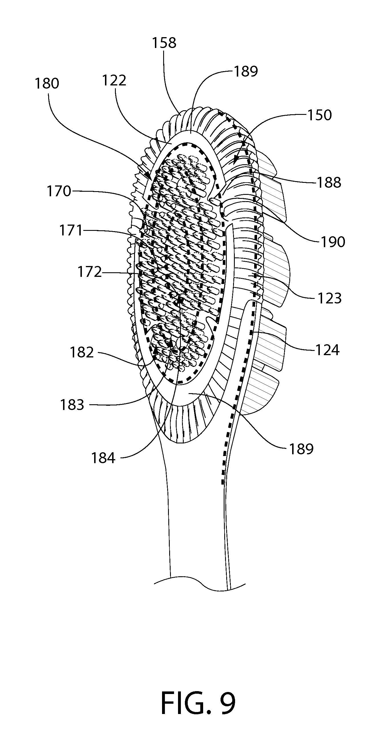
FIG. 9 is a rear perspective view of the head of the oral care implement of FIG. 1.
DETAILED DESCRIPTION
The following description of the preferred embodiment(s) is merely exemplary in nature and is in no way intended to limit the invention, its application, or uses.
The description of illustrative embodiments according to principles of the present invention is intended to be read in connection with the accompanying drawings, which are to be considered part of the entire written description. In the description of the exemplary embodiments of the invention disclosed herein, any reference to direction or orientation is merely intended for convenience of description and is not intended in any way to limit the scope of the present invention. Relative terms such as "lower," "upper," "horizontal," "vertical," "above," "below," "up," "down," "left," "right," "top," "bottom," "front" and "rear" as well as derivatives thereof (e.g., "horizontally," "downwardly," "upwardly," etc.) should be construed to refer to the orientation as then described or as shown in the drawing under discussion. These relative terms are for convenience of description only and do not require that the apparatus be constructed or operated in a particular orientation unless explicitly indicated as such. Terms such as "attached," "affixed," "connected," "coupled," "interconnected," "secured" and similar refer to a relationship wherein structures are secured or attached to one another either directly or indirectly through intervening structures, as well as both movable or rigid attachments or relationships, unless expressly described otherwise. Moreover, the features and benefits of the invention are described by reference to the exemplary embodiments illustrated herein. Accordingly, the invention expressly should not be limited to such exemplary embodiments, even if indicated as being preferred. The discussion herein describes and illustrates some possible non-limiting combinations of features that may exist alone or in other combinations of features. The scope of the invention is defined by the claims appended hereto.
In the following description, the invention is discussed in terms of a manual toothbrush. However, in other forms, the invention could be in the form of other oral care implements including a soft-tissue cleansing implement, a powered toothbrush, a refill head, or other ansate implements designed for oral care.
Referring first to FIG. 1, an oral care implement 100 is illustrated according to one embodiment of the present invention. The oral care implement 100 generally comprises a handle 110 and a head 120. The handle 110 provides the user with a mechanism by which he/she can readily grip and manipulate the oral care implement 100. The handle 110 is generically illustrated and may be formed of many different shapes, sizes, materials and by a variety of manufacturing methods that are well-known to those skilled in the art. For example, the handle 110 can be constructed of elastomers, polypropylene, SAN, ABS, or even paper products such as a typical lollipop stick. If desired, the handle 110 may include a suitable textured grip (not shown) made of a thermoplastic elastomer or can be a multi-part construction. The details of the handle 110 are not limiting of the present invention and, thus, require no further discussion for purposes of the present invention.
The oral care implement 100 extends from a proximal end 112 to a distal end 113. The head 120 is operably connected to a distal end of the handle 110. Generally, the head 110 and the handle 120 of the toothbrush are preferably formed as a single unitary structure using a molding, milling, machining or other suitable process. However, in other embodiments, the handle 110 and head 120 may be formed as separate components which are operably connected at a later stage of the manufacturing process by any suitable technique known in the art, including without limitation thermal welding, a tight-fit assembly, a coupling sleeve, adhesion, or fasteners. Whether the head 120 and handle 110 are of a unitary or multi-piece construction (including connection techniques) is not limiting of the present invention unless specifically stated in the claims.
It should be noted at this time that relative terms such as distal, middle, proximal, upper, lower, top, bottom, left, right etc. are merely used to delineate relative positions of the components of the oral care implement 100 with respect to one another and are not intended to be in any further way limiting of the present invention
Referring to FIGS. 2 and 3, the head 120 extends along a longitudinal axis A-A from a proximal end 131 of the head 120 to a distal end 132 of the head 120. The head 120 generally comprises a front surface 121, a rear surface 122 that is opposite the front surface 121 (as shown in FIG. 4) and a peripheral surface 123. The peripheral surface 123 extends between the front surface 121 and the rear surface 122, connecting the front and rear surfaces 121, 122 and defining a perimeter edge 124 of the front surface 121. The front surface 121, the rear surface 122, and the peripheral surface 123 of the head 120 can take on a wide variety of shapes and contours, none of which are limiting of the present invention. For example, the surfaces can be planar, contoured or combinations thereof. Furthermore, while the head 120 is normally widened relative to the neck 111 of the handle 110, it could in some constructions simply be a continuous extension or narrowing of the handle 110.
Referring to FIGS. 3-6 concurrently, the head 120 further comprises an elastomeric component 150, which may include a bumper portion 151 that forms a distal-most section 130 of the peripheral surface 123 and a wall portion 152 located along a distal-most section of the perimeter edge 124. The wall portion 152 protrudes above the front surface 121. The wall portion 152 extends along the perimeter edge 124 in a continuous manner from a first point 1 of the perimeter edge 124 to a second point 2 of the perimeter edge 124. The first and second points 1, 2 are located on opposite sides of the longitudinal axis A-A. The wall portion 152 may comprise a first ramped portion 153, a second ramped portion 154, and an apex portion 155 (best visible in FIG. 7). The apex portion 155 is disposed between the first ramped position 153 and the second ramped position 154.
In one embodiment, the first ramped portion 153 may extend from the first point 1 to a fourth point 4 of the perimeter edge 124. The fourth point 4 is located between the first and third points 1, 3. The height of the first ramped portion 153 of the wall portion 152 increases from the first point 1 to the fourth point 4. The second ramped portion 154 may extend from the second point 2 to a fifth point 5 of the perimeter edge 124. The fifth point 5 is located between the second and third points 2, 3. The height of the second ramped portion 154 of the wall portion 152 increases from the second point 2 to the fourth point 5. The apex portion 155 may extend from the fourth point 4 to the fifth point 5. The apex portion 155, in the exemplified embodiment, has a substantially constant height from the fourth point 4 to the fifth point 5.
The wall portion 152 has a maximum height H.sub.max at the third point 3 of the perimeter edge 124, which is located between the first and second points 1, 2. The third point 3 is located on the longitudinal axis IV and on the apex portion 155. The wall portion 152 has a substantially zero height at the first and second points 1, 2.
In another embodiment, the first ramped portion 153 may extend from the first point 1 to the third point 3, wherein the height of the first ramped portion 153 of the wall portion 152 may increase from the first point 1 to the third point 3. The second ramped portion 154 may extend from the second point 2 to the third point 3, wherein the height of the second ramped portion 154 of the wall portion 152 may increase from the second point 2 to the third point 3. In such an embodiment, the apex portion 155 may take the form of a single point, rather than a section.
The first and second ramped portions 153, 154 may comprise an upper edge 156, 157 that appear as a linear slope when the head is viewed in side profile (see FIGS. 5 and 6). The first upper edge 156 of the first ramped portion 153 may extend upward from the front surface 121 at an angle of O.sub.1 and the second upper edge 157 of the second ramped portion 154 may extend upward from the front surface 121 at an angle of O.sub.2. The O.sub.1 and O.sub.2 may be the same or different and each O.sub.1 and O.sub.2 may be selected from an angle ranging from about 10.degree. to about 60.degree.; preferably from about 15.degree. to about 45.degree.; and more preferably about 25.degree. to about 35.degree..
The wall portion 152 and a transverse line B-B extending between the first and second points 1, 2 of the perimeter edge 124 collectively define a distal-most area 130 of the front surface 121 of the head 120. A remaining portion of the perimeter edge 125 may be free of the wall portion 152. The remaining portion of the perimeter edge 125 may extend from the first point 1 to a sixth point 6 alone the perimeter edge 125. The remaining portion of the perimeter edge 125 may also extend from the second point 2 to a seventh point 7 along the perimeter edge 125. In some embodiments, the wall portion 152 is arcuate and comprises a convex inner surface and a concave outer surface. The wall portion 152 may be free of through-holes.
Referring to FIGS. 5 and 6, the elastomeric component 150 may further comprise a plurality of spaced-apart ridges 158 protruding from an outer surface of the bumper portion 151 and an outer surface of the wall portion 152. The elastomeric component 150 may also comprise a plurality of spaced-apart ridges 158 protruding from an outer surface along at least a portion of the peripheral surface 123. The elastomeric component 150 may further comprise a soft tissue cleanser 180 on the rear surface 122 of the head 120, the soft tissue cleanser 180 comprising a plurality of protuberances 181. In some embodiments, the elastomeric component 150 may be an integrally formed component and include the bumper portion 151, the wall portion 152, the plurality of spaced-apart ridges 158, and the soft tissue cleanser 180.
The soft tissue cleanser 180 is preferably constructed of a biocompatible resilient material suitable for uses in an oral hygiene apparatus, such as a thermoplastic elastomer. As an example, one preferred elastomeric material is styrene-ethylene/butylene-styrene block copolymer (SEBS) manufactured by GLS Corporation. Nevertheless, SEBS material from other manufacturers or other materials. The soft tissue cleanser 180 can be constructed of different types of resilient materials or the same resilient material with one or more different characteristics, such as color, hardness, density, flavor, and/or sensate.
As shown in FIG. 4, the head 120 comprises a base portion 126 formed of a rigid plastic, such as polypropylene. The elastomeric component 150 may be injection molded to the base portion 126. The base portion 126 comprises a peripheral wall 127 that forms a basin 128, the head 120 further comprises a head plate 160 disposed within the basin 128 and coupled to the base portion 126.
The head plate 160 comprises a plurality of through holes 161. A plurality of cleaning elements 140 are provided that extend through the through holes 161 of the head plate. The plurality of cleaning elements 140 extend from the front surface 121 of the head 120.
Each of the plurality of cleaning elements 140 comprise a cleaning portion 141 extending from an upper surface 162 of the head plate 160 for cleaning contact with an oral surface. Each of the plurality of cleaning elements 140 also includes a melt portion 142 located between a lower surface of the head plate 163 and a floor of the basin 129. The melt portions 142 anchor the cleaning elements 140 to the head. While the plurality of cleaning elements 140 are particularly suited for brushing teeth, the plurality of cleaning elements 140 can also be used to clean oral soft tissue, such as a tongue, gums, or cheeks instead of or in addition to teeth.
As used herein, the term "cleaning element" is used in a generic sense to refer to any structure that can be used to clean or massage an oral surface through relative surface contact. Common examples of "cleaning elements" include, without limitation, filament bristles, fiber bristles, nylon bristles, spiral bristles, rubber bristles, elastomeric protrusions, flexible polymer protrusions, combinations thereof and/or structures containing such materials or combinations.
Referring to FIGS. 4-7, the plurality of cleaning elements 140 comprises a plurality of distal cleaning elements 143 extending from the distal-most area 130 of the front surface 121. The maximum height H.sub.max of the wall portion 152 is less than or equal to one half of a height H.sub.CE of a shortest one of the plurality of distal tooth cleaning elements 143. In one embodiment, the maximum height H.sub.max of the wall portion 152 is less than or equal to one third of the height H.sub.CE of a shortest one of the plurality of distal tooth cleaning elements 143. In another embodiment, the maximum height H.sub.max of the wall portion 152 is less than or equal to one quarter of the height H.sub.CE of a shortest one of the plurality of distal tooth cleaning elements 143. The plurality of distal tooth cleaning elements 143 may comprise tapered bristles.
In some embodiments the peripheral surface 123 may comprise the elastomeric component 150 and the rigid plastic used to form the base portion 126 of the head 120. In another embodiment, the peripheral surface 123 may be entirely formed by the elastomeric component 150.
With reference to FIGS. 5-9, the details of the elastomeric component 150 includes the soft tissue cleanser 180, which will now be discussed. The soft tissue cleanser 180 is on the rear surface 122 of the head 120 and comprises a pad 188 that forms at least a portion of the rear surface 122 of the head 120 of the oral care implement 100. The pad 188 is preferably injection molded directly to the head 120 but can be molded separately and later fixed to the head 120 if desired, for example by an adhesive or sonic welding. The pad 188 extends from a distal end 132 of the head 120 to a proximal end 131 of the head 120 and may cover substantially the entire width of the head 120, extending from a first lateral edge 133 of the head 120 towards a second lateral edge 134 of the head 120.
The elastomeric component 150 may have one or more exposed underlying head portions 189 extending therethrough exposing the base portion 126. The exposed underlying head portions 189 may be a variety of geometric shapes--such as circular or crescent shapes. In one embodiment, the exposed underlying head portions 189 define a boundary for which a plurality of protuberances 181 are positioned on the rear surface 122 of the head 120. In one embodiment, crescent shaped exposed underlying head portions 189 define an annular shaped layout of the plurality of protuberances 181 when looking at the rear surface 122 of the head 120.
The pad 188 includes an exposed top surface 190 on the rear surface 122 of the head. The plurality of protuberances 181 protrude from the rear surface 122 of the head 120 from the top surface 190 of the pad 188. The plurality of protuberances 181 may include a first plurality of protuberances 182 arranged in a first annular zone 170 on the rear surface 122. The first annular zone 170 is the area defined between a first dotted line 173 and a second dotted line 174. Each of the first plurality of protuberances 182 may have a height between a first predetermined height H.sub.1 and a second predetermined height H.sub.2, the second predetermined height H.sub.2 being greater than the first predetermined height H.sub.1.
The plurality of protuberances 181 may further include a plurality of second protuberances 183 protruding from the rear surface 122 of the head 120 and arranged in a second annular zone 171 on the rear surface 122. The first annular zone 170 surrounds the second annular zone 171. The second annular zone 171 is the area defined between the second dotted line 174 and a third dotted line 175. Each of the second plurality of protuberances 183 may have a height between the second predetermined height H.sub.2 and a third predetermined height H.sub.3, the third predetermined height H.sub.3 being greater than the second predetermined height H.sub.2.
The plurality of protuberances 181 may further include a plurality of third protuberances 184 protruding from the rear surface 122 of the head 120 and arranged in a third zone 172 on the rear surface 122. The second annular zone 171 surrounds the third annular zone 173. The third zone 172 may be annular zone or it may be a central zone. The third annular zone 172 is the area defined within the third dotted line 175. Each of the third plurality of protuberances 184 have a height between the third predetermined height H.sub.3 and a fourth predetermined height H.sub.4, the fourth predetermined height H.sub.4 being greater than the third predetermined height H.sub.3.
In some embodiments, the plurality of first protuberances 182 may comprise protuberances having a plurality of different heights between the first and second predetermined heights H.sub.1, H.sub.2. The plurality of second protuberances 183 may comprise protuberances having a plurality of different heights between the second and third predetermined heights H.sub.2, H.sub.3. The plurality of third protuberances 184 may comprises protuberances having a plurality of different heights between the third and fourth predetermined heights H.sub.3, H.sub.4.
In certain embodiments, the plurality of first protuberances 182 consist only of protuberances having a height between the first and second predetermined heights H.sub.1, H.sub.2. The plurality of second protuberances 183 consist only of protuberances having a height between the second and third predetermined heights H.sub.2, H.sub.3. The plurality of third protuberances 184 consist only of protuberances having a height between the third and fourth predetermined heights H.sub.3, H.sub.4.
The first predetermined height H.sub.1 may be in a range of 0.5 mm to 1.5 mm, the second predetermined height H.sub.2 may be in a range of 1.5 mm to 2.5 mm, the third predetermined height H.sub.3 may be in a range of 2.5 mm to 3.5 mm, and the fourth predetermined height H.sub.4 may be in a range of 3.5 mm to 6.0 mm.
In some embodiments, free ends of the first, second and third protuberances 182, 183, 184 collectively form a convex side profile (see FIGS. 5 and 6). In some embodiments, the free ends of the first, second and third protuberances 182, 183, 184 may also collectively form a convex top profile (see FIG. 7).
The plurality of first protuberances 182 comprises first conical nubs, the plurality of second protuberances 183 comprises second conical nubs, and the plurality of third protuberances 184 comprises third conical nubs. In one embodiment, the plurality of first protuberances 182 consists only of the first conical nubs, the plurality of second protuberances 183 consists only of second conical nubs, and the plurality of third protuberances 184 consists only of the third conical nubs. The plurality of conical nubs extends from the pad portion 188.
As used herein a "nub" is generally meant to include a column-like protrusion (without limitation to the cross-sectional shape of the protrusion) which is upstanding from a base surface. In a general sense, the nub, in the preferred construction, has a height that is greater than the width at the base of the nub (as measured in the longest direction). Nevertheless, nubs could include projections wherein the widths and heights are roughly the same or wherein the heights are somewhat smaller than the base widths. Moreover, in some circumstances (e.g., where the nub tapers to a tip or includes a base portion that narrows to a smaller projection), the base width can be substantially larger than the height.
The first, second, and third plurality of nubs 182-184 are designed to engage the oral soft tissue to significantly reduce a major source of bad breath in people and improve hygiene. The first, second, and third plurality of nubs 182-184 enable removal of microflora and other debris from the tongue and other soft tissue surfaces within the mouth. The tongue, in particular, is prone to develop bacterial coatings that are known to harbor organisms and debris that can contribute to bad breath. This microflora can be found in the recesses between the papillae on most of the tongue's upper surface as well as along other soft tissue surfaces in the mouth. When engaged or otherwise pulled against a tongue surface, for example, the first, second, and third nubs provide for gentle engagement with the soft tissue while reaching downward into the recesses of adjacent papillae of the tongue. The elastomeric construction of the soft tissue cleanser 180 also enables a top surface 190 of the pad 188 to follow the natural contours of the oral tissue surfaces, such as the tongue, cheeks, lips, and gums of a user. Moreover, the first, second, and third nubs are able to flex as needed to traverse and clean the soft tissue surfaces in the mouth along which it is moved.
In the illustrated embodiment, the first, second, and third nubs are preferably conically shaped. As used herein, "conically shaped" or "conical" is meant to include true cones, frusto-conically shaped elements, and other shapes that taper to a narrow end and thereby resemble a cone irrespective of whether they are uniform, continuous in their taper, or have rounded cross-sections. The base portion of each the conically shaped first, second, and third nubs 182-184 is larger than the corresponding tip portion.
Furthermore, the resilient material of the first, second, and/or third annular zones 170, 171, 172 may also be imbued with a sensory material, which can be any suitable biocompatible medication or chemical for oral use. The sensory material is released inside the mouth, lips, or cheeks by way of several methods, including but not limited to abrasion, a temperature change, a change in pH or dissolution. In one embodiment, the sensory material is a sensate that provides a biochemical sensory response to the inside tissue and surfaces of the mouth. Such a sensory response is understood to result from stimulation of the trigeminal nerve of a human. A sensate generally produces a physiological effect without a taste, with such effect usually represented by the terms cooling, tingle, and hot (or heat). Sensates are usually derived from single compounds that are not volatile and that do not have a smell or taste per se. As one example, a chemical known as capsaicin, found naturally in chile peppers, can be used to provide a tingle, a hot or warm massage, or a heating or warm, soothing sensation to a user. Capsaicin is also known to provide pain relief and numbing sensations when topically applied. Some examples of sensates that produce cooling sensations include (-)-menthol and camphor. Most of the polyols, including maltitol syrup, sorbitol, mannitol, erythritol, isomalt and xylitol, also provide a cooling sensation. The coolest of the polyols, erythritol, provides a distinct cooling sensation. Both erythritol and xylitol cool the mouth and fight the sensation of dry mouth commonly associated with prescription drugs and dental hygiene products. Erythritol is a naturally occurring four-carbon structure. Xylitol is a five-carbon sugar found in fruits and vegetables and made in small amounts by the human system as a metabolic intermediate.
In another embodiment, the sensory material is provided as flavoring agent for causing an olfactory sensory response in a human. A flavor agent is commonly understood to include a mixture of compounds that are volatile and produce an aromatic effect and that stimulate the olfactory bulb. Flavors are generally transmitted through the nasal passages, and are often selected and used for their unique association with certain consumer benefits, such as lavender for stress relief or relaxation. Another flavor example is chamomile, which has a strong, aromatic smell and is often used medicinally against sore stomach and as a relaxant to help you fall asleep. Chamomile is also used as a mouthwash against oral mucositis (the swelling, irritation, and ulceration of the mucosal cells that line the digestive tract).
In one embodiment, the first, second, and/or third annular zone 170, 171, 172 can be imbued with both a sensate component and a flavor component. The soft tissue cleanser 180 may be an integrally formed singular component.
Referring now to FIGS. 6-8 concurrently, one preferred embodiment of manufacturing the head 120 via an injection molding process will be described. First, the head 120 is formed by injecting a liquefied hard plastic, such as PP or SAN, into a mold having the appropriately shaped fill cavity. Once the head 120 is sufficiently cooled (the structure of which is described above), an outer mold is placed about the head 120 for forming the elastomeric component 150. The elastomeric component 150 is formed by an overmolding process which involves injecting a single shot of a first type of liquefied thermoplastic elastomer about the head 122 via a first port having a first size. The first type of liquefied thermoplastic elastomer surrounds the head 120 and fills available gaps/grooves on the head 120. As a result, the elastomeric component 150 is formed as illustrated. The elastomeric component 150 may also be made using separate shots, each using different types of thermoplastic elastomer, to form different components of the elastomeric component 150--for example one shot for the pad 188 and another shot for the plurality of protuberances 181. This allows the pad 188 and the plurality of protuberances 181 to be formed of different types of elastomers, which may be useful for elastomeric components 150 having differing colors, flavors, sensates or material properties, such as hardness or density.
Another embodiment of manufacturing the head 120 includes the head plate 160 which clusters of the plurality of cleaning elements 140 are inserted through the through holes 161. The rear ends of the plurality of cleaning elements 140 are melted thereby affixing the plurality of cleaning elements 140 to the head plate 160. The melted portions form the melt portion 142 that adheres to the head plate 160 and bonds the plurality of cleaning elements 140 to each other.
As used throughout, ranges are used as shorthand for describing each and every value that is within the range. Any value within the range can be selected as the terminus of the range. In addition, all references cited herein are hereby incorporated by referenced in their entireties. In the event of a conflict in a definition in the present disclosure and that of a cited reference, the present disclosure controls.
While the invention has been described with respect to specific examples including presently preferred modes of carrying out the invention, those skilled in the art will appreciate that there are numerous variations and permutations of the above described systems and techniques. It is to be understood that other embodiments may be utilized and structural and functional modifications may be made without departing from the scope of the present invention. Thus, the spirit and scope of the invention should be construed broadly as set forth in the appended claims.
* * * * *
D00000
D00001
D00002
D00003
D00004
D00005
D00006
D00007
D00008
D00009
XML
uspto.report is an independent third-party trademark research tool that is not affiliated, endorsed, or sponsored by the United States Patent and Trademark Office (USPTO) or any other governmental organization. The information provided by uspto.report is based on publicly available data at the time of writing and is intended for informational purposes only.
While we strive to provide accurate and up-to-date information, we do not guarantee the accuracy, completeness, reliability, or suitability of the information displayed on this site. The use of this site is at your own risk. Any reliance you place on such information is therefore strictly at your own risk.
All official trademark data, including owner information, should be verified by visiting the official USPTO website at www.uspto.gov. This site is not intended to replace professional legal advice and should not be used as a substitute for consulting with a legal professional who is knowledgeable about trademark law.