Wearable device and terminal
Zhang , et al. Oc
U.S. patent number 10,454,297 [Application Number 15/217,478] was granted by the patent office on 2019-10-22 for wearable device and terminal. This patent grant is currently assigned to BOE TECHNOLOGY GROUP CO., LTD.. The grantee listed for this patent is BOE TECHNOLOGY GROUP CO., LTD.. Invention is credited to Zhanfeng Cao, Yanjun Li, Wei Zhang.


| United States Patent | 10,454,297 |
| Zhang , et al. | October 22, 2019 |
Wearable device and terminal
Abstract
Disclosed are a wearable device and a terminal. The wearable device includes: a wearable component and a power supply component fixed on the wearable component. The power supply component includes a first supporting surface, an energy conversion element and an energy storage element. The energy conversion element includes: a magnetic structure, an elastic structure and an induction coil. One end of the magnetic structure is connected to the first supporting surface through the elastic structure. The magnetic structure moves with respect to the induction coil through the elastic structure when the wearable device is shaken, such that an alternating current is generated in the induction coil. The energy storage element is adapted to store electric energy obtained by the energy conversion element.
| Inventors: | Zhang; Wei (Beijing, CN), Cao; Zhanfeng (Beijing, CN), Li; Yanjun (Beijing, CN) | ||||||||||
|---|---|---|---|---|---|---|---|---|---|---|---|
| Applicant: |
|
||||||||||
| Assignee: | BOE TECHNOLOGY GROUP CO., LTD.
(Beijing, CN) |
||||||||||
| Family ID: | 54578734 | ||||||||||
| Appl. No.: | 15/217,478 | ||||||||||
| Filed: | July 22, 2016 |
Prior Publication Data
| Document Identifier | Publication Date | |
|---|---|---|
| US 20170033589 A1 | Feb 2, 2017 | |
Foreign Application Priority Data
| Jul 30, 2015 [CN] | 2015 1 0461236 | |||
| Current U.S. Class: | 1/1 |
| Current CPC Class: | H02J 50/70 (20160201); H02J 50/10 (20160201); H02J 7/025 (20130101); H02J 7/32 (20130101); H02J 7/345 (20130101) |
| Current International Class: | H02J 7/02 (20160101); H02J 7/32 (20060101); H02J 50/70 (20160101); H02J 50/10 (20160101); H02J 7/34 (20060101) |
| Field of Search: | ;320/108 |
References Cited [Referenced By]
U.S. Patent Documents
| 4245640 | January 1981 | Hunt |
| 4321572 | March 1982 | Studer |
| 4837494 | June 1989 | Maier |
| 4904256 | February 1990 | Yamaguchi |
| 5315279 | May 1994 | Ito |
| 5358461 | October 1994 | Bailey, Jr. |
| 5434549 | July 1995 | Hirabayashi |
| 5804892 | September 1998 | Schwan |
| 5907231 | May 1999 | Watanabe |
| 5917307 | June 1999 | Watanabe |
| 6084381 | July 2000 | Kajiura |
| 6211765 | April 2001 | Ito |
| 6346791 | February 2002 | Barguirdjian |
| 6512437 | January 2003 | Jin |
| 6559560 | May 2003 | Jin |
| 7038335 | May 2006 | Choi |
| 7323790 | January 2008 | Taylor |
| 7501726 | March 2009 | Waters |
| 7514818 | April 2009 | Abe |
| 7646863 | January 2010 | Johnston |
| 7688036 | March 2010 | Yarger |
| 8304937 | November 2012 | Cederwall |
| 8387599 | March 2013 | McAlister |
| 8555860 | October 2013 | McAlister |
| 8581426 | November 2013 | Seike |
| 8587154 | November 2013 | Fells |
| 8610311 | December 2013 | Grimes |
| 8629572 | January 2014 | Phillips |
| 8635985 | January 2014 | McAlister |
| 8883351 | November 2014 | Todoriki |
| 8907533 | December 2014 | Battlogg |
| 8946919 | February 2015 | Phillips |
| 8946920 | February 2015 | Phillips |
| 8952560 | February 2015 | Phillips |
| 8963358 | February 2015 | Phillips |
| 8997725 | April 2015 | McAlister |
| 9341152 | May 2016 | McAlister |
| 9476400 | October 2016 | Phillips |
| 9490729 | November 2016 | Hasegawa |
| 9553477 | January 2017 | Yang |
| 9581116 | February 2017 | McAlister |
| 9595384 | March 2017 | Nakamura |
| 9620270 | April 2017 | Uemoto |
| 9624900 | April 2017 | Phillips |
| 9641093 | May 2017 | Artelsmair |
| 9644601 | May 2017 | Phillips |
| 9645248 | May 2017 | Wallace |
| 9647483 | May 2017 | Bana |
| 9774715 | September 2017 | Ma |
| 9837198 | December 2017 | Liu |
| 9859051 | January 2018 | Ren |
| 9866037 | January 2018 | Maekawa |
| 9893536 | February 2018 | Zhou |
| 9948358 | April 2018 | Fells |
| 2002/0057164 | May 2002 | Jin |
| 2005/0244016 | November 2005 | Norris |
| 2006/0208839 | September 2006 | Taylor |
| 2006/0214628 | September 2006 | Chang |
| 2007/0091519 | April 2007 | Abe |
| 2008/0074083 | March 2008 | Yarger |
| 2008/0116849 | May 2008 | Johnston |
| 2009/0219139 | September 2009 | Slesinski |
| 2009/0230786 | September 2009 | Liu |
| 2010/0183993 | July 2010 | McAlister |
| 2011/0042476 | February 2011 | McAlister |
| 2011/0048374 | March 2011 | McAlister |
| 2012/0007437 | January 2012 | Fells |
| 2012/0028127 | February 2012 | Wei |
| 2012/0109399 | May 2012 | Tran |
| 2012/0139389 | June 2012 | Bohringer |
| 2012/0258367 | October 2012 | Jung |
| 2012/0320492 | December 2012 | Radivojevic |
| 2013/0019460 | January 2013 | Mayes |
| 2013/0026999 | January 2013 | Lee |
| 2013/0249325 | September 2013 | Park et al. |
| 2013/0266869 | October 2013 | Todoriki |
| 2013/0335011 | December 2013 | Bohringer |
| 2014/0042824 | February 2014 | Fells |
| 2014/0048037 | February 2014 | McAlister |
| 2014/0063864 | March 2014 | Liu |
| 2014/0117673 | May 2014 | Phillips |
| 2014/0117674 | May 2014 | Phillips |
| 2014/0203902 | July 2014 | Shippee |
| 2014/0255776 | September 2014 | Song |
| 2014/0263697 | September 2014 | McAlister |
| 2014/0292570 | October 2014 | Wallace |
| 2014/0313001 | October 2014 | Phillips |
| 2014/0333144 | November 2014 | Ikeuchi |
| 2014/0339928 | November 2014 | Phillips |
| 2014/0345563 | November 2014 | McAlister |
| 2014/0361642 | December 2014 | Seo |
| 2015/0035634 | February 2015 | Nakamura |
| 2015/0042101 | February 2015 | Luo |
| 2015/0064565 | March 2015 | Todoriki |
| 2015/0145258 | May 2015 | Phillips |
| 2015/0162120 | June 2015 | Ren |
| 2015/0179323 | June 2015 | Uemoto |
| 2015/0221432 | August 2015 | Zhou |
| 2015/0288300 | October 2015 | Hasegawa |
| 2015/0349575 | December 2015 | Yang |
| 2015/0357833 | December 2015 | Maekawa |
| 2015/0364931 | December 2015 | Ren |
| 2016/0010619 | January 2016 | Phillips |
| 2016/0100651 | April 2016 | Rastegar |
| 2016/0252071 | September 2016 | Phillips |
| 2017/0113154 | April 2017 | Kheterpal |
| 2017/0151577 | June 2017 | Baltz |
| 2017/0169924 | June 2017 | Uemoto |
| 2017/0198401 | July 2017 | Phillips |
| 2017/0208161 | July 2017 | Ma |
| 2017/0237061 | August 2017 | Song |
| 2017/0279311 | September 2017 | Hanabusa |
| 2017/0350241 | December 2017 | Shi |
| 2385460 | Jun 2000 | CN | |||
| 201229835 | Apr 2009 | CN | |||
| 202840645 | Mar 2013 | CN | |||
| 103935207 | Jul 2014 | CN | |||
Other References
|
First Office Action regarding Chinese application No. 201510461236.X, dated Dec. 27, 2016. Translation provided by Dragon Intellectual Property Law Firm. cited by applicant . Second Office Action regarding Chinese Application No. 201510461236.X, dated Jul. 11, 2017. Translation provided by Dragon Intellectual Property Law Firm. cited by applicant. |
Primary Examiner: Grant; Robert
Assistant Examiner: Trischler; John T
Attorney, Agent or Firm: Harness, Dickey & Pierce, P.L.C.
Claims
What is claimed is:
1. A wearable device, comprising: a wearable component and a power supply component fixed on the wearable component; wherein the power supply component comprises a first supporting surface, an energy conversion element and an energy storage element; wherein the energy conversion element comprises: a magnetic structure, an elastic structure and an induction coil; one end of the magnetic structure is connected to the first supporting surface through the elastic structure; and the magnetic structure moves with respect to the induction coil through the elastic structure when the wearable device is shaken, such that an electric current is generated in the induction coil; wherein the energy storage element is adapted to store electric energy obtained by the energy conversion element; wherein the magnetic structure is a pillar-shaped structure, a diameter of a middle section of the pillar-shaped structure is less than a diameter of each of two end sections of the pillar-shaped structure, and the induction coil is wound around the middle section of the pillar-shaped structure; wherein a cross section of the pillar-shaped structure comprises two edges each of which is a smooth curve, the cross section being parallel to a center axis of the pillar-shaped structure; wherein the power supply component further comprises a second supporting surface; and the energy conversion element further comprises a limiting structure, and the limiting structure is positioned below another end of the magnetic structure and fixed on the second supporting surface, and is adapted to limit maximum displacement of the magnetic structure with respect to the induction coil; and wherein the limiting structure comprises an airbag or an elastic cushion.
2. The wearable device according to claim 1, wherein the elastic structure of the energy conversion element comprises a plurality of micro springs; and the one end of the magnetic structure is connected to the first supporting surface through the plurality of micro springs.
3. The wearable device according to claim 1, wherein the power supply component is fixed on the wearable component through a velcro tape, a snap fit or a slot lock.
4. The wearable device according to claim 1, wherein a diameter of the limiting structure is greater than the diameter of each of the two end sections of the pillar-shaped structure.
5. The wearable device according to claim 1, wherein the energy storage element comprises a rectifier transformer and an electric energy storage; and the electric energy storage is connected to the induction coil through the rectifier transformer to store the electric energy obtained by the energy conversion element.
6. The wearable device according to claim 5, wherein there is a plurality of energy conversion elements, and the electric energy storage is connected to the induction coil of each of the plurality of energy conversion elements through the rectifier transformer.
7. The wearable device according to claim 5, wherein the electric energy storage is a capacitor whose electrodes are made of graphene.
8. A terminal, comprising: at least one power supply component; wherein each of the at least one power supply component comprises a first supporting surface, an energy conversion element and an energy storage element; wherein the energy conversion element comprises a magnetic structure, an elastic structure and an induction coil; one end of the magnetic structure is connected to the first supporting surface through the elastic structure; and the magnetic structure moves with respect to the induction coil through the elastic structure when the terminal is shaken, such that an electric current is generated in the induction coil; wherein the energy storage element is adapted to store electric energy obtained by the energy conversion element; wherein the magnetic structure is a pillar-shaped structure, a diameter of a middle section of the pillar-shaped structure is less than a diameter of each of two end sections of the pillar-shaped structure, and the induction coil is wound around the middle section of the pillar-shaped structure; wherein a cross section of the pillar-shaped structure comprises two edges each of which is a smooth curve, the cross section being parallel to a center axis of the pillar-shaped structure; the power supply component further comprises a second supporting surface; and the energy conversion element further comprises a limiting structure, and the limiting structure is positioned below another end of the magnetic structure and fixed on the second supporting surface and is adapted to limit maximum displacement of the magnetic structure with respect to the induction coil; and the limiting structure comprises an airbag or an elastic cushion.
9. The terminal according to claim 8, wherein the elastic structure of the energy conversion element comprises a plurality of micro springs; and the one end of the magnetic structure is connected to the first supporting surface through the plurality of micro springs.
10. The terminal according to claim 8, wherein a diameter of the limiting structure is greater than the diameter of each of the two end sections of the pillar-shaped structure.
11. The terminal according to claim 8, wherein the energy storage element comprises a rectifier transformer and an electric energy storage; and the electric energy storage is connected to the induction coil through the rectifier transformer to store the electric energy obtained by the energy conversion element.
12. The terminal according to claim 11, wherein the each of the at least one power supply component comprises a plurality of energy conversion elements, and the electric energy storage is connected to the induction coil of each of the plurality of energy conversion elements through the rectifier transformer.
Description
CROSS-REFERENCE TO RELATED APPLICATION
The present application claims a priority to Chinese Patent Application No. 201510461236.X filed on Jul. 30, 2015, the disclosure of which is incorporated in its entirety by reference herein.
TECHNICAL FIELD
The present disclosure relates to the field of power supplying technology for electronic devices, and in particular to a wearable device and a terminal.
BACKGROUND
With the development of terminal technology, a user may use a terminal in various aspects. However, there is no significant breakthrough in capacity of a battery of the terminal. In many cases, due to limited battery capacity and high power consumption, the user may be subjected to inconvenient charging of the terminal.
Especially, in some emergency circumstances, the user may charge the terminal only by means of a portable power source or a wireless charging station. Actually, battery capacity of the portable power source is usually not too high for good portability; and in case of wireless charging, power conversion efficiency is low and health of the user may be affected by generated high radiation.
In view of the above, a power supplying solution which overcomes the above-mentioned drawbacks is required.
SUMMARY
It is provided, in the present disclosure, a wearable device and a terminal capable of being charged with high efficiency anytime and anywhere.
It is provided a wearable device in the present disclosure, including: a wearable component and a power supply component fixed on the wearable component. The power supply component includes a first supporting surface, an energy conversion element and an energy storage element. The energy conversion element includes: a magnetic structure, an elastic structure and an induction coil; one end of the magnetic structure is connected to the first supporting surface through the elastic structure; and the magnetic structure moves with respect to the induction coil through the elastic structure when the wearable device is shaken, such that an electric current is generated in the induction coil. The energy storage element is adapted to store electric energy obtained by the energy conversion element.
Optionally, the elastic structure of the energy conversion element may include multiple micro springs; and the one end of the magnetic structure is connected to the first supporting surface through the multiple micro springs.
Optionally, the power supply component may further include a second supporting surface; and the energy conversion element may further include a limiting structure, which is positioned below another end of the magnetic structure and fixed on the second supporting surface, and is for limiting maximum displacement of the magnetic structure with respect to the induction coil.
Optionally, the limiting structure may include an airbag and an elastic cushion.
Optionally, the magnetic structure may be a pillar-shaped structure, a diameter of a middle section of the pillar-shaped structure is less than that of each of two end sections of the pillar-shaped structure, and the induction coil is wound around the middle section of the pillar-shaped structure.
Optionally, the energy storage element may include a rectifier transformer and an electric energy storage; and the electric energy storage is connected to the induction coil through the rectifier transformer and stores the electric energy obtained by the energy conversion element.
Optionally, there are multiple energy conversion elements, and the electric energy storage is connected to the induction coil of each of the multiple power conversion elements through the rectifier transformer.
Optionally, the electric energy storage is a capacitor whose electrodes are made of graphene.
Optionally, the power supply component may be fixed on the wearable component through a velcro tape, a snap fit or a slot lock.
It is further provided a terminal in the present disclosure, including: at least one power supply component. Each of the at least one power supply component includes a first supporting surface, an energy conversion element and an energy storage element. The energy conversion element includes: a magnetic structure, an elastic structure and an induction coil; one end of the magnetic structure is connected to the first supporting surface through the elastic structure; and the magnetic structure moves with respect to the induction coil through the elastic structure when the terminal is shaken, such that an electric current is generated in the induction coil. The energy storage element is adapted to store electric energy obtained by the energy conversion element.
Optionally, the elastic structure of the energy conversion element may include multiple micro springs; and the one end of the magnetic structure is connected to the first supporting surface through the multiple micro springs.
Optionally, the power supply component may further include a second supporting surface; and the energy conversion element may further include a limiting structure which is positioned below another end of the magnetic structure and fixed on the second supporting surface, and is for limiting maximum displacement of the magnetic structure with respect to the induction coil.
Optionally, the limiting structure may include an airbag and an elastic cushion.
Optionally, the magnetic structure may be a pillar-shaped structure, a diameter of a middle section of the pillar-shaped structure is less than that of each of two end sections of the pillar-shaped structure, and the induction coil is wound around the middle section of the pillar-shaped structure.
Optionally, the energy storage element may include a rectifier transformer and an electric energy storage; and the electric energy storage is connected to the induction coil through the rectifier transformer and stores the electric energy obtained by the energy conversion element.
Optionally, each of the at least one power supply component is provided with multiple power conversion elements; and the electric energy storage is connected to the induction coil of each of the multiple power conversion elements through the rectifier transformer.
In technical solutions of the present disclosure, since the wearable device and the terminal may easily get shaken when being carried, the kinetic energy generated through shake is converted into the electric energy and the electric energy is stored, thereby achieving charging anytime and anywhere. Compared with the related technologies where a portable power source or a wireless charging station is used to perform charging, the wearable device and the terminal in the present disclosure can generate electric energy by themselves; hence, such wearable device and terminal can be charged in various scenarios and has a very high use value.
BRIEF DESCRIPTION OF THE DRAWINGS
FIG. 1 is a schematic structural diagram of a wearable device provided in the present disclosure;
FIG. 2 is a schematic structural diagram of a power supply component provided in the present disclosure;
FIG. 3 is a schematic structural diagram of a power supply component including multiple power conversion elements provided in the present disclosure;
FIG. 4 is a schematic structural diagram of a terminal provided in the present disclosure; and
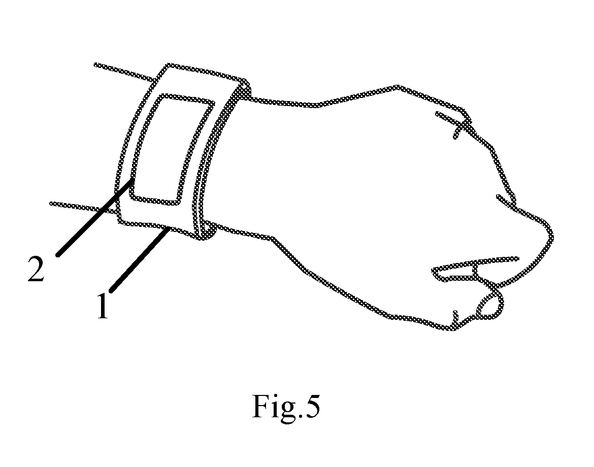
FIG. 5 is a schematic structural diagram of a wearable device provided in the present disclosure.
DETAILED DESCRIPTION OF THE EMBODIMENTS
To further clarify technical solutions and advantages of the present disclosure, the present disclosure is described in detail hereinafter in conjunction with drawings and embodiments.
According to the embodiments of the present disclosure, it is provided a wearable device and a terminal, capable of being charged efficiently anytime and anywhere.
As shown in FIG. 1, a wearable device according to some embodiments of the present disclosure includes a wearable component 1 and a power supply component 2 fixed on the wearable component 1.
The power supply component 2 further includes a first supporting surface, an energy conversion element 21 for converting kinetic energy of the wearable device into electric energy, and an energy storage element 22 for storing the electric energy obtained by the energy conversion element 21.
As shown in FIG. 2, the energy conversion element 21 includes a magnetic structure 21A, an elastic structure 21B and an induction coil 21C. One end of the magnetic structure 21A is connected to the first supporting surface 23 of the power supply component 2 through the elastic structure 21B. The first supporting surface 23 may be a surface of a main structure of the power supply component 2. In the embodiments, the magnetic structure 21A moves with respect to the induction coil 21C through the elastic structure 21B when the wearable device is shaken, such that an electric current is generated in the induction coil 21C.
In the embodiments, since the wearable device may easily get shaken when being carried, the kinetic energy generated through shake is converted into the electric energy and the electric energy is stored, thereby achieving charging anytime and anywhere. Compared with the related technologies where a portable power source or a wireless charging station is used to perform charging, the wearable device according to the embodiments of the present disclosure can generate electric energy by itself; hence, such wearable device can be charged in various scenarios and has a very high use value.
Optionally, in some embodiments of the present disclosure, as shown in FIG. 2, the magnetic structure 21A may be a pillar-shaped structure. A diameter of a middle section of the pillar-shaped structure is less than that of each of the two end sections of the pillar-shaped structure; thus, there is much room for winding the induction coil 21C and energy conversion efficiency is improved.
In a practical application, the elastic structure 21B of the energy conversion element 21 may include multiple micro springs, and one end of the magnetic structure 21A is connected to the first supporting surface 23 through the multiple micro springs.
Further, in order to avoid falling off or damage of the magnetic structure 21A due to severe shake of the wearable device, as shown in FIG. 2, the energy conversion element 21 may further include a limiting structure 21D, which is positioned below another end of the magnetic structure 21A and fixed on a second supporting surface 24 of the power supply component 2. The second supporting surface 24 may be a surface of the main structure of the power supply component 2. The limiting structure 21D is capable of limiting maximum displacement of the magnetic structure 21A. Practically, the limiting structure 21D may be an article for buffering the magnetic structure 21A, such as, an airbag, an elastic cushion or the like.
In the embodiments, as shown in FIG. 2, the energy storage element 22 includes a rectifier transformer 22A and an electric energy storage 22B.
The electric energy storage 22B is connected to the induction coil through the rectifier transformer 22A. An alternating current generated by the induction coil 21C is converted, by the rectifier transformer 22A, into a direct current whose voltage is in range of a rated voltage of the electric energy storage 22B, and the direct current is stored by the electric energy storage 22B.
Optionally, in some embodiments, the electric energy storage 22B may be a super capacitor whose electrodes are made of graphene. Charging efficiency and discharging efficiency of the super capacitor are much higher than those of a general electric energy storage.
In a practical application, as shown in FIG. 3, in order to increase efficiency of the wearable device in generating a current, the power supply component 2 may include multiple energy conversion elements 21, and the electric energy storage 22B of the energy storage element 22 is connected to the induction coil 21C of each of the multiple energy conversion elements 21 through the rectifier transformer 22A.
A principle for generating electric energy of the power supply component of the present disclosure is explained above. In addition, electric energy may be generated in other manners for the skilled in the art. For example, a wearable device may utilize body temperature of a user to generate the electric energy, the power supply component may be provided with a closed loop circuit formed by connecting two sections of different metals, and a current may be generated through "Seebeck" effect in the case that temperatures of connecting points of the two sections of different metals are different. Actually, different charging manners may be combined for further improving charging efficiency.
Practically, the power supply component may be fixed on the wearable component through a velcro tape, a snap fit, a slot lock or the like. In the case that the wearable component is designed as a ring structure, the wearable device may be worn as an accessory such as a bracelet (for example, as shown in FIG. 5, the wearable device is implemented as a bracelet, which includes the wearable component 1 and the power supply component 2) or a necklace by the user or may be bound to a vehicle such as a car or the like. Electric energy, which is obtained by converting the shake of a moving human body or a moving vehicle, can be stored. Moreover, the power supply component may be removed from the wearable component and used as a portable power source at any time.
Moreover, as shown in FIG. 4, it is further provided a terminal 3 according to some embodiments of the present disclosure. The terminal may be a smart phone, a tablet computer, an electronic reader, etc. The terminal 3 includes: at least one power supply component 2 including an energy conversion element 21 and an energy storage element 22. The energy conversion element 21 is adapted to convert kinetic energy of the terminal into electric energy, and the energy storage element 22 is adapted to store the electric energy obtained by the energy conversion element 21.
In the embodiments, since the terminal may easily get shaken when being carried, the kinetic energy generated through shake is converted into the electric energy and the electric energy is stored, thereby achieving charging anytime and anywhere. Compared with the related technologies where a portable power source or a wireless charging station is used to perform charging, the terminal according to the embodiments of the present disclosure can generate the electric energy by itself; hence, such terminal can be charged in various scenarios and has a very high use value.
In conjunction with FIG. 2, the power supply component 2 further includes a first supporting surface 23 and the energy conversion element 21 includes a magnetic structure 21A, an elastic structure 21B and an induction coil 21C; one end of the magnetic structure 21A is connected to the first supporting surface 23 through the elastic structure 21B, the magnetic structure 21A moves with respect to the induction coil 21C through the elastic structure 21B when the terminal 3 is shaken, such that an electric current is generated in the induction coil 21C. In a practical application, the elastic structure 21B may include multiple micro springs, and the one end of the magnetic structure 21A is connected to the first supporting surface 23 through the multiple micro springs.
Moreover, the power supply component 2 further includes a first supporting surface 24, and a limiting structure 21D is positioned below another end of the magnetic structure 21A and fixed on the second supporting surface 24. The limiting structure 21D is adapted to limit maximum displacement of the magnetic structure 21A with respect to the induction coil 21C, so as to avoid falling off or damage of the magnetic structure 21A due to severe shake of the terminal. Practically, the limiting structure 21D may be an article for buffering the magnetic structure 21A, such as, an airbag, an elastic cushion or the like.
Optionally, the magnetic structure 21A may be a pillar-shaped structure. A diameter of a middle section of the pillar-shaped structure is less than that of each of the two end sections of the pillar-shaped structure; thus, there is much room for winding the induction coil 21C and energy conversion efficiency is improved.
In the embodiments, as shown in FIG. 4, the energy storage element 22 includes a rectifier transformer 22A and an electric energy storage 22B.
The electric energy storage 22B is connected to the induction coil through the rectifier transformer 22A. An alternating current generated by the induction coil 21C is converted by the rectifier transformer 22A into a direct current and the direct current is stored in the electric energy storage 22B.
Optionally, in some embodiments, the electric energy storage 22B may be a super capacitor whose electrodes are made of graphene. Charging efficiency and discharging efficiency of the super capacitor are much higher than those of a general electric energy storage.
Moreover, in order to increase efficiency of the terminal 3 in generating a current, the power supply component 2 may include multiple energy conversion elements; and the electric energy storage 22B of the energy storage element 22 is connected to the induction coil 21C of each of the multiple energy conversion elements 21 through the rectifier transformer 22A.
The terminal of the present disclosure is described above. When being carried by the user, the terminal can convert the kinetic energy generated from shake into the electric energy, thereby achieving charging anytime and anywhere.
In a practical application, the energy storage element may be used in an emergency and may be provided to different terminal elements depending on of the amount of energy stored in the energy storage element, for example, may be used for providing emergency lighting, supplying power for a GPS module of a mobile phone or supplying power for a battery of the terminal.
In summary, with the wearable device and the terminal of the present disclosure, the kinetic energy can be converted into the electric energy for charging, and such charging manner is healthy and environmentally friendly, and is worth being popularized.
Those described above are preferred embodiments of the present disclosure. It should be noted that, for the skilled in the art, improvements and modifications may also be made without departing from the principle of the disclosure. Those improvements and modifications should also be included in the scope of protection of the present disclosure.
* * * * *
D00000
D00001
D00002
D00003
XML
uspto.report is an independent third-party trademark research tool that is not affiliated, endorsed, or sponsored by the United States Patent and Trademark Office (USPTO) or any other governmental organization. The information provided by uspto.report is based on publicly available data at the time of writing and is intended for informational purposes only.
While we strive to provide accurate and up-to-date information, we do not guarantee the accuracy, completeness, reliability, or suitability of the information displayed on this site. The use of this site is at your own risk. Any reliance you place on such information is therefore strictly at your own risk.
All official trademark data, including owner information, should be verified by visiting the official USPTO website at www.uspto.gov. This site is not intended to replace professional legal advice and should not be used as a substitute for consulting with a legal professional who is knowledgeable about trademark law.