Operating an infusion pump system
Estes Oc
U.S. patent number 10,449,294 [Application Number 14/988,697] was granted by the patent office on 2019-10-22 for operating an infusion pump system. This patent grant is currently assigned to Bigfoot Biomedical, Inc.. The grantee listed for this patent is Bigfoot Biomedical, Inc.. Invention is credited to Mark Estes.
| United States Patent | 10,449,294 |
| Estes | October 22, 2019 |
Operating an infusion pump system
Abstract
An infusion pump system can operate to control dispensation of medicine according to a closed-loop delivery mode and according to an open-loop delivery mode. In the closed-loop delivery mode, the system can determine user-specific settings. In the open-loop delivery mode, the system can determine insulin dosages for dispensation based at least in part on the user-specific settings that were determined during the closed-loop delivery mode.
| Inventors: | Estes; Mark (Milpitas, CA) | ||||||||||
|---|---|---|---|---|---|---|---|---|---|---|---|
| Applicant: |
|
||||||||||
| Assignee: | Bigfoot Biomedical, Inc.
(Milpitas, CA) |
||||||||||
| Family ID: | 68242077 | ||||||||||
| Appl. No.: | 14/988,697 | ||||||||||
| Filed: | January 5, 2016 |
| Current U.S. Class: | 1/1 |
| Current CPC Class: | A61M 5/14244 (20130101); A61M 5/1413 (20130101); A61M 5/1723 (20130101); A61M 5/1452 (20130101); A61M 2005/14208 (20130101); A61M 2230/005 (20130101); A61M 2205/502 (20130101); A61M 2205/3576 (20130101); A61M 2230/201 (20130101) |
| Current International Class: | A61M 5/172 (20060101); A61M 5/142 (20060101); A61M 5/14 (20060101); A61M 5/145 (20060101) |
References Cited [Referenced By]
U.S. Patent Documents
| 2605765 | August 1952 | Kollsman |
| 3886938 | June 1975 | Szabo et al. |
| 4077405 | March 1978 | Haerten et al. |
| 4151845 | May 1979 | Clemens |
| 4231368 | November 1980 | Becker |
| 4265241 | May 1981 | Portner et al. |
| 4300554 | November 1981 | Hessberg et al. |
| 4313439 | February 1982 | Babb et al. |
| 4398908 | August 1983 | Siposs |
| 4435173 | March 1984 | Siposs et al. |
| 4443218 | April 1984 | DeCant, Jr. et al. |
| 4475901 | October 1984 | Kraegen et al. |
| 4493704 | January 1985 | Beard et al. |
| 4529401 | July 1985 | Leslie et al. |
| 4850817 | July 1989 | Nason et al. |
| 5045064 | September 1991 | Idriss |
| 5088981 | February 1992 | Howson et al. |
| 5190522 | March 1993 | Wojcicki et al. |
| 5250027 | October 1993 | Lewis et al. |
| 5261882 | November 1993 | Sealfon et al. |
| 5314412 | May 1994 | Rex |
| 5335994 | August 1994 | Weynant Nee Girones |
| 5338157 | August 1994 | Blomquist |
| 5342180 | August 1994 | Daoud |
| 5395340 | March 1995 | Lee |
| 5411487 | May 1995 | Castagna |
| 5545143 | August 1996 | Fischell et al. |
| 5551850 | September 1996 | Williamson et al. |
| 5569186 | October 1996 | Lord et al. |
| 5626566 | May 1997 | Petersen et al. |
| 5637095 | June 1997 | Nason et al. |
| 5665065 | September 1997 | Colman et al. |
| 5741216 | April 1998 | Hemmingsen et al. |
| 5772635 | June 1998 | Dastur et al. |
| 5816306 | October 1998 | Giacomel |
| 5822715 | October 1998 | Worthington |
| 5852803 | December 1998 | Ashby, III et al. |
| 5873731 | February 1999 | Prendergast |
| 5919167 | July 1999 | Mulhauser |
| 5925018 | July 1999 | Ungerstedt |
| 5928201 | July 1999 | Poulsen et al. |
| 5947934 | September 1999 | Hansen et al. |
| 5951530 | September 1999 | Steengaard et al. |
| 5957889 | September 1999 | Poulsen et al. |
| 5984894 | November 1999 | Poulsen et al. |
| 5984897 | November 1999 | Petersen et al. |
| 5997475 | December 1999 | Bortz |
| 6003736 | December 1999 | Ljunggren |
| 6010485 | January 2000 | Buch-Rasmussen et al. |
| 6033377 | March 2000 | Rasmussen et al. |
| 6045537 | April 2000 | Klitmose |
| 6074372 | June 2000 | Hansen |
| 6110149 | August 2000 | Klitgaard et al. |
| 6126595 | October 2000 | Amano |
| 6156014 | December 2000 | Petersen et al. |
| 6171276 | January 2001 | Lippe et al. |
| 6231540 | May 2001 | Smedegaard |
| 6233471 | May 2001 | Berner et al. |
| 6248067 | June 2001 | Causey, III et al. |
| 6248090 | June 2001 | Jensen et al. |
| 6248093 | June 2001 | Moberg |
| 6277098 | August 2001 | Klitmose et al. |
| 6302855 | October 2001 | Lav et al. |
| 6302869 | October 2001 | Klitgaard |
| 6375638 | April 2002 | Nason et al. |
| 6379301 | April 2002 | Worthington et al. |
| 6379339 | April 2002 | Klitgaard et al. |
| 6381496 | April 2002 | Meadows et al. |
| 6397098 | May 2002 | Uber, III et al. |
| 6404098 | June 2002 | Kayama et al. |
| 6461331 | October 2002 | Van Antwerp |
| 6474219 | November 2002 | Klitmose et al. |
| 6485461 | November 2002 | Mason et al. |
| 6508788 | January 2003 | Preuthun |
| 6524280 | February 2003 | Hansen et al. |
| 6533183 | March 2003 | Aasmul et al. |
| 6537251 | March 2003 | Klitmose |
| 6540672 | April 2003 | Simonsen et al. |
| 6544212 | April 2003 | Galley |
| 6544229 | April 2003 | Danby et al. |
| 6547764 | April 2003 | Larsen et al. |
| 6551276 | April 2003 | Mann et al. |
| 6554798 | April 2003 | Mann et al. |
| 6554800 | April 2003 | Nezhadian et al. |
| 6558320 | May 2003 | Causey, III et al. |
| 6558345 | May 2003 | Houben et al. |
| 6558351 | May 2003 | Steil et al. |
| 6562001 | May 2003 | Lebel et al. |
| 6562011 | May 2003 | Buch-Rasmussen et al. |
| 6564105 | May 2003 | Starkweather et al. |
| 6569126 | May 2003 | Poulsen et al. |
| 6571128 | May 2003 | Lebel et al. |
| 6572542 | June 2003 | Houben |
| 6572545 | June 2003 | Knobbe et al. |
| 6577899 | June 2003 | Lebel et al. |
| 6582404 | June 2003 | Klitgaard et al. |
| 6585644 | July 2003 | Lebel et al. |
| 6585699 | July 2003 | Ljunggreen et al. |
| 6587199 | July 2003 | Luu |
| 6589229 | July 2003 | Connelly et al. |
| 6599281 | July 2003 | Struys et al. |
| 6605067 | August 2003 | Larsen |
| 6605072 | August 2003 | Struys et al. |
| 6613019 | September 2003 | Munk |
| 6641533 | November 2003 | Causey, III et al. |
| 6648821 | November 2003 | Lebel et al. |
| 6650951 | November 2003 | Jones et al. |
| 6656158 | December 2003 | Mahoney et al. |
| 6656159 | December 2003 | Flaherty |
| 6659948 | December 2003 | Lebel et al. |
| 6659978 | December 2003 | Kasuga et al. |
| 6659980 | December 2003 | Moberg et al. |
| 6663602 | December 2003 | Moller |
| 6668196 | December 2003 | Villegas et al. |
| 6669669 | December 2003 | Flaherty et al. |
| 6687546 | February 2004 | Lebel et al. |
| 6690192 | February 2004 | Wing |
| 6691043 | February 2004 | Ribeiro, Jr. |
| 6692457 | February 2004 | Flaherty |
| 6692472 | February 2004 | Hansen et al. |
| 6694191 | February 2004 | Starkweather et al. |
| 6699218 | March 2004 | Flaherty et al. |
| 6702779 | March 2004 | Connelly et al. |
| 6715516 | April 2004 | Ohms et al. |
| 6716198 | April 2004 | Larsen |
| 6723072 | April 2004 | Flaherty et al. |
| 6723077 | April 2004 | Pickup et al. |
| 6733446 | May 2004 | Lebel et al. |
| 6736796 | May 2004 | Shekalim |
| 6740059 | May 2004 | Flaherty |
| 6740072 | May 2004 | Starkweather et al. |
| 6740075 | May 2004 | Lebel et al. |
| 6744350 | June 2004 | Blomquist |
| 6749587 | June 2004 | Flaherty |
| 6752787 | June 2004 | Causey, III et al. |
| 6758810 | July 2004 | Lebel et al. |
| 6768425 | July 2004 | Flaherty et al. |
| 6780156 | August 2004 | Haueter et al. |
| 6786246 | September 2004 | Ohms et al. |
| 6786890 | September 2004 | Preuthun et al. |
| 6796970 | September 2004 | Klitmose et al. |
| 6799149 | September 2004 | Hartlaub |
| 6809653 | October 2004 | Mann et al. |
| 6810290 | October 2004 | Lebel et al. |
| 6811533 | November 2004 | Lebel et al. |
| 6811534 | November 2004 | Bowman, IV et al. |
| 6813519 | November 2004 | Lebel et al. |
| 6827702 | December 2004 | Lebel et al. |
| 6830558 | December 2004 | Flaherty et al. |
| 6852104 | February 2005 | Blomquist |
| 6854620 | February 2005 | Ramey |
| 6854653 | February 2005 | Eilersen |
| 6855129 | February 2005 | Jensen et al. |
| 6872200 | March 2005 | Mann et al. |
| 6873268 | March 2005 | Lebel et al. |
| 6878132 | April 2005 | Kipfer |
| 6893415 | May 2005 | Madsen et al. |
| 6899695 | May 2005 | Herrera |
| 6899699 | May 2005 | Enggaard |
| 6922590 | July 2005 | Whitehurst |
| 6923763 | August 2005 | Kovatchev et al. |
| 6925393 | August 2005 | Kalatz |
| 6936006 | August 2005 | Sabra |
| 6936029 | August 2005 | Mann et al. |
| 6945961 | September 2005 | Miller et al. |
| 6948918 | September 2005 | Hansen |
| 6950708 | September 2005 | Bowman, IV et al. |
| 6960192 | November 2005 | Flaherty et al. |
| 6979326 | December 2005 | Mann et al. |
| 6997911 | February 2006 | Klitmose |
| 6997920 | February 2006 | Mann et al. |
| 7005078 | February 2006 | Van Lintel et al. |
| 7008399 | March 2006 | Larson et al. |
| 7014625 | March 2006 | Bengtsson |
| 7018360 | March 2006 | Flaherty et al. |
| 7025743 | April 2006 | Mann |
| 7029455 | April 2006 | Flaherty |
| 7054836 | May 2006 | Christensen et al. |
| 7060059 | June 2006 | Keith et al. |
| 7066910 | June 2006 | Bauhahn et al. |
| 7104972 | September 2006 | Moller et al. |
| 7109878 | September 2006 | Mann et al. |
| 7128727 | October 2006 | Flaherty et al. |
| 7133329 | November 2006 | Skyggebjerg et al. |
| 7179226 | February 2007 | Crothall et al. |
| 7204823 | April 2007 | Estes et al. |
| 7220240 | May 2007 | Struys et al. |
| 7232423 | June 2007 | Mernoe et al. |
| 7267665 | September 2007 | Steil et al. |
| 7278983 | October 2007 | Ireland et al. |
| 7291107 | November 2007 | Hellwig et al. |
| 7354420 | April 2008 | Steil et al. |
| 7402153 | July 2008 | Steil et al. |
| 7404796 | July 2008 | Ginsberg |
| 7429255 | September 2008 | Thompson |
| 7491187 | February 2009 | Van Den Berghe et al. |
| 7547281 | June 2009 | Hayes et al. |
| 7569030 | August 2009 | Lebel et al. |
| 7570980 | August 2009 | Ginsberg |
| 7591801 | September 2009 | Brauker et al. |
| 7651845 | January 2010 | Doyle, III et al. |
| 7670288 | March 2010 | Sher |
| 7704226 | April 2010 | Mueller, Jr. et al. |
| 7734323 | June 2010 | Blomquist et al. |
| 7785313 | August 2010 | Mastrototaro |
| 7806853 | October 2010 | Wittmann et al. |
| 7806854 | October 2010 | Damiano et al. |
| 7806886 | October 2010 | Kanderian, Jr. et al. |
| 7815602 | October 2010 | Mann et al. |
| 7819843 | October 2010 | Mann et al. |
| 7850641 | December 2010 | Lebel et al. |
| 7879026 | February 2011 | Estes et al. |
| 7946985 | May 2011 | Mastrototaro et al. |
| 7959598 | June 2011 | Estes |
| 7967812 | June 2011 | Jasperson et al. |
| 7976492 | July 2011 | Brauker et al. |
| 8029459 | October 2011 | Rush et al. |
| 8062249 | November 2011 | Wilinska et al. |
| 8088098 | January 2012 | Yodfat et al. |
| 8105268 | January 2012 | Lebel et al. |
| 8114023 | February 2012 | Ward et al. |
| 8152789 | April 2012 | Starkweather et al. |
| 8206296 | June 2012 | Jennewine |
| 8206350 | June 2012 | Mann et al. |
| 8208984 | June 2012 | Blomquist et al. |
| 8226556 | July 2012 | Hayes et al. |
| 8246540 | August 2012 | Ginsberg |
| 8257300 | September 2012 | Budiman et al. |
| 8267893 | September 2012 | Moberg et al. |
| 8273052 | September 2012 | Damiano et al. |
| 8318154 | November 2012 | Frost et al. |
| 8348844 | January 2013 | Kunjan et al. |
| 8348886 | January 2013 | Kanderian, Jr. et al. |
| 8348923 | January 2013 | Kanderian, Jr. et al. |
| 8352011 | January 2013 | Van Antwerp et al. |
| 8417311 | April 2013 | Rule |
| 8439834 | May 2013 | Schmelzeisen-Redeker et al. |
| 8439897 | May 2013 | Yodfat et al. |
| 8454576 | June 2013 | Mastrototaro et al. |
| 8460231 | June 2013 | Brauker et al. |
| 8467972 | June 2013 | Rush |
| 8475409 | July 2013 | Tsoukalis |
| 8480655 | July 2013 | Jasperson et al. |
| 8548544 | October 2013 | Kircher, Jr. et al. |
| 8548552 | October 2013 | Tsoukalis |
| 8551045 | October 2013 | Sie et al. |
| 8560082 | October 2013 | Wei |
| 8560131 | October 2013 | Haueter et al. |
| 8562558 | October 2013 | Kamath et al. |
| 8562587 | October 2013 | Kovatchev et al. |
| 8568713 | October 2013 | Frost et al. |
| 8579854 | November 2013 | Budiman et al. |
| 8579879 | November 2013 | Palerm et al. |
| 8585591 | November 2013 | Sloan et al. |
| 8585593 | November 2013 | Kovatchev et al. |
| 8585637 | November 2013 | Wilinska et al. |
| 8585638 | November 2013 | Blomquist |
| 8597274 | December 2013 | Sloan et al. |
| 8615366 | December 2013 | Galley et al. |
| 8622988 | January 2014 | Hayter |
| 8679016 | March 2014 | Mastrototaro et al. |
| 8734422 | March 2014 | Hayter |
| 8690820 | April 2014 | Cinar et al. |
| 8694115 | April 2014 | Goetz et al. |
| 8706691 | April 2014 | McDaniel et al. |
| 8718949 | May 2014 | Blomquist et al. |
| 8721585 | May 2014 | Brauker et al. |
| 8727982 | May 2014 | Jennewine |
| 8734428 | May 2014 | Blomquist |
| 8747315 | June 2014 | Brauker et al. |
| 8762070 | June 2014 | Doyle, III et al. |
| 8771222 | July 2014 | Kanderian, Jr. et al. |
| 8777896 | July 2014 | Starkweather et al. |
| 8777924 | July 2014 | Kanderian, Jr. et al. |
| 8784364 | July 2014 | Kamen et al. |
| 8784369 | July 2014 | Starkweather et al. |
| 8784370 | July 2014 | Lebel et al. |
| 8795224 | August 2014 | Starkweather et al. |
| 8795252 | August 2014 | Hayter |
| 8876755 | November 2014 | Taub et al. |
| 8882741 | November 2014 | Brauker et al. |
| 8903501 | December 2014 | Perryman et al. |
| 8919180 | December 2014 | Gottlieb et al. |
| 8920401 | December 2014 | Brauker et al. |
| 8926585 | January 2015 | Brauker et al. |
| 8945094 | February 2015 | Nordh |
| 8956291 | February 2015 | Valk et al. |
| 8956321 | February 2015 | DeJournett |
| 8977504 | March 2015 | Hovorka |
| 8992475 | March 2015 | Mann et al. |
| 9034323 | May 2015 | Frost et al. |
| 9050413 | June 2015 | Brauker et al. |
| 9056165 | June 2015 | Steil et al. |
| 9056168 | June 2015 | Kircher, Jr. et al. |
| 9089305 | July 2015 | Hovorka |
| 9149233 | October 2015 | Kamath et al. |
| 9155843 | October 2015 | Brauker et al. |
| 9247901 | February 2016 | Kamath et al. |
| 9320471 | April 2016 | Hayes et al. |
| 9333298 | May 2016 | Kim et al. |
| 9415157 | August 2016 | Mann et al. |
| 9474855 | October 2016 | McCann et al. |
| 9480796 | November 2016 | Starkweather et al. |
| 9486172 | November 2016 | Cobelli et al. |
| 9486578 | November 2016 | Finan et al. |
| 2001/0056262 | December 2001 | Cabiri |
| 2002/0004651 | January 2002 | Ljndggreen et al. |
| 2002/0007154 | January 2002 | Hansen et al. |
| 2002/0016534 | February 2002 | Trepagnier et al. |
| 2002/0040208 | April 2002 | Flaherty et al. |
| 2002/0091358 | July 2002 | Klitmose |
| 2002/0126036 | September 2002 | Flaherty et al. |
| 2003/0055380 | March 2003 | Flaherty |
| 2003/0060753 | March 2003 | Starkweather et al. |
| 2003/0088238 | March 2003 | Poulsen et al. |
| 2003/0104982 | March 2003 | Flaherty |
| 2003/0130616 | March 2003 | Flaherty |
| 2003/0065308 | April 2003 | Lebel et al. |
| 2003/0208113 | May 2003 | Poulsen et al. |
| 2003/0114836 | June 2003 | Estes |
| 2003/0181852 | September 2003 | Mann et al. |
| 2003/0187525 | October 2003 | Mann et al. |
| 2003/0191431 | October 2003 | Mann et al. |
| 2003/0195462 | October 2003 | Mann et al. |
| 2003/0199825 | October 2003 | Flaherty |
| 2003/0212364 | November 2003 | Mann et al. |
| 2003/0216683 | November 2003 | Shekalim |
| 2004/0010207 | January 2004 | Flaherty et al. |
| 2004/0019325 | January 2004 | Shekalim |
| 2004/0078028 | January 2004 | Flaherty et al. |
| 2004/0087894 | January 2004 | Shekalim |
| 2004/0064088 | April 2004 | Gorman et al. |
| 2004/0064096 | April 2004 | Flaherty et al. |
| 2004/0092865 | April 2004 | Gorman et al. |
| 2004/0092878 | April 2004 | Flaherty et al. |
| 2004/0116866 | April 2004 | Flaherty et al. |
| 2004/0127844 | May 2004 | Flaherty |
| 2004/0153032 | May 2004 | Flaherty et al. |
| 2004/0167464 | May 2004 | Flaherty |
| 2004/0171983 | June 2004 | Gorman et al. |
| 2004/0176720 | June 2004 | Gorman et al. |
| 2004/0176727 | July 2004 | Flaherty |
| 2004/0193025 | August 2004 | Garribotto et al. |
| 2004/0204673 | August 2004 | Ireland et al. |
| 2004/0220551 | September 2004 | Kipfer |
| 2004/0235446 | September 2004 | Shekalim |
| 2004/0220517 | November 2004 | Starkweather et al. |
| 2004/0260233 | December 2004 | Garibotto et al. |
| 2005/0021005 | January 2005 | Flaherty et al. |
| 2005/0021104 | January 2005 | DiLorenzo |
| 2005/0022274 | January 2005 | Campbell et al. |
| 2005/0090808 | January 2005 | Flaherty et al. |
| 2005/0160858 | January 2005 | Campbell et al. |
| 2005/0065465 | March 2005 | Lebel et al. |
| 2005/0065760 | March 2005 | Murtfeldt et al. |
| 2005/0095063 | May 2005 | Fathallah et al. |
| 2005/0171512 | August 2005 | Flaherty |
| 2005/0171513 | August 2005 | Mann et al. |
| 2005/0182366 | August 2005 | Flaherty |
| 2005/0192561 | August 2005 | Vogt et al. |
| 2005/0203461 | September 2005 | Flaherty et al. |
| 2005/0215982 | September 2005 | Flaherty et al. |
| 2005/0222645 | September 2005 | Malave et al. |
| 2005/0238507 | October 2005 | Malave et al. |
| 2005/0240544 | October 2005 | DiIanni et al. |
| 2005/0245878 | November 2005 | Mernoe et al. |
| 2005/0251097 | November 2005 | Mernoe |
| 2005/0267402 | December 2005 | Stewart et al. |
| 2005/0273059 | December 2005 | Mernoe et al. |
| 2005/0277890 | December 2005 | Stewart et al. |
| 2006/0041229 | February 2006 | Garibotto et al. |
| 2006/0069382 | March 2006 | Pedersen |
| 2006/0074381 | April 2006 | Malave et al. |
| 2006/0095014 | May 2006 | Ethelfeld |
| 2006/0135913 | June 2006 | Ethelfeld |
| 2006/0142698 | June 2006 | Ethelfeld |
| 2006/0173406 | August 2006 | Hayes et al. |
| 2006/0178633 | August 2006 | Garibotto et al. |
| 2006/0184119 | August 2006 | Remde et al. |
| 2006/0200073 | September 2006 | Radmer et al. |
| 2006/0206054 | September 2006 | Shekalim |
| 2006/0224109 | October 2006 | Steil et al. |
| 2006/0247581 | November 2006 | Pedersen et al. |
| 2007/0016127 | January 2007 | Staib et al. |
| 2007/0073228 | March 2007 | Mernoe et al. |
| 2007/0073235 | March 2007 | Estes et al. |
| 2007/0073236 | March 2007 | Mernoe et al. |
| 2007/0118405 | May 2007 | Campbell et al. |
| 2007/0124002 | May 2007 | Estes et al. |
| 2007/0156092 | July 2007 | Estes et al. |
| 2007/0167905 | July 2007 | Estes et al. |
| 2007/0167912 | July 2007 | Causey et al. |
| 2007/0173761 | July 2007 | Kanderian, Jr. et al. |
| 2007/0179444 | August 2007 | Causey et al. |
| 2007/0219432 | September 2007 | Thompson |
| 2007/0282299 | December 2007 | Hellwig |
| 2008/0033357 | February 2008 | Mann et al. |
| 2008/0109050 | May 2008 | John |
| 2008/0125700 | May 2008 | Moberg et al. |
| 2008/0129535 | June 2008 | Thompson |
| 2008/0147004 | June 2008 | Mann et al. |
| 2008/0147050 | June 2008 | Mann et al. |
| 2008/0172027 | July 2008 | Blomquist |
| 2008/0177165 | July 2008 | Blomquist et al. |
| 2008/0183060 | July 2008 | Steil et al. |
| 2008/0188796 | August 2008 | Steil et al. |
| 2008/0201325 | August 2008 | Doniger et al. |
| 2008/0269714 | October 2008 | Mastrototaro |
| 2008/0269723 | October 2008 | Mastrototaro et al. |
| 2008/0275384 | November 2008 | Mastrototaro |
| 2008/0294094 | November 2008 | Mhatre et al. |
| 2008/0294142 | November 2008 | Patel et al. |
| 2008/0306434 | December 2008 | Dobbles et al. |
| 2008/0306444 | December 2008 | Brister |
| 2008/0312512 | December 2008 | Brukalo et al. |
| 2009/0043291 | February 2009 | Thompson |
| 2009/0048584 | February 2009 | Thompson |
| 2009/0069784 | March 2009 | Estes et al. |
| 2009/0069787 | March 2009 | Estes et al. |
| 2009/0099507 | April 2009 | Koops |
| 2009/0118664 | May 2009 | Estes et al. |
| 2009/0143916 | June 2009 | Boll et al. |
| 2009/0149728 | June 2009 | Van Antwerp et al. |
| 2009/0192722 | July 2009 | Shariati et al. |
| 2009/0105636 | August 2009 | Hayter et al. |
| 2009/0234213 | September 2009 | Hayes et al. |
| 2009/0264856 | October 2009 | Lebel et al. |
| 2010/0010329 | January 2010 | Taub et al. |
| 2010/0056992 | March 2010 | Hayter |
| 2010/0057040 | March 2010 | Hayter |
| 2010/0057041 | March 2010 | Hayter |
| 2010/0057042 | March 2010 | Hayter |
| 2010/0094251 | April 2010 | Estes |
| 2010/0121167 | May 2010 | McGarraugh |
| 2010/0165795 | July 2010 | Elder et al. |
| 2010/0168538 | July 2010 | Keenan et al. |
| 2010/0168820 | July 2010 | Maniak et al. |
| 2010/0174266 | July 2010 | Estes |
| 2010/0179409 | July 2010 | Kamath et al. |
| 2010/0228110 | September 2010 | Tsoukalis |
| 2010/0280441 | November 2010 | Wilinska et al. |
| 2010/0298765 | November 2010 | Budiman et al. |
| 2010/0324382 | December 2010 | Cantwell et al. |
| 2011/0015511 | January 2011 | Bousamra et al. |
| 2011/0034909 | February 2011 | Lebel et al. |
| 2011/0071464 | March 2011 | Palerm |
| 2011/0098637 | April 2011 | Hill |
| 2011/0106011 | May 2011 | Cinar et al. |
| 2011/0106050 | May 2011 | Yodfat |
| 2011/0112505 | May 2011 | Starkweather et al. |
| 2011/0112506 | May 2011 | Starkweather et al. |
| 2011/0118699 | May 2011 | Yodfat |
| 2011/0130716 | June 2011 | Estes et al. |
| 2011/0184380 | July 2011 | Starkweather et al. |
| 2011/0208155 | August 2011 | Palerm et al. |
| 2011/0313390 | December 2011 | Roy et al. |
| 2012/0010600 | January 2012 | Wilinska et al. |
| 2012/0046606 | February 2012 | Arefieg |
| 2012/0065894 | March 2012 | Tubb et al. |
| 2012/0078067 | March 2012 | Kovatchev et al. |
| 2012/0109113 | May 2012 | Lebel et al. |
| 2012/0123234 | May 2012 | Atlas et al. |
| 2012/0136336 | May 2012 | Mastrototaro et al. |
| 2012/0150556 | June 2012 | Galasso et al. |
| 2012/0172694 | July 2012 | Desborough et al. |
| 2012/0172802 | July 2012 | Blomquist |
| 2012/0197207 | August 2012 | Stefanski |
| 2012/0203467 | August 2012 | Kamath et al. |
| 2012/0209208 | August 2012 | Stefanski |
| 2012/0227737 | September 2012 | Mastrototaro et al. |
| 2012/0238853 | September 2012 | Arefieg |
| 2012/0245448 | September 2012 | Shariati et al. |
| 2012/0245556 | September 2012 | Kovatchev et al. |
| 2012/0245855 | September 2012 | Kamath et al. |
| 2012/0246106 | September 2012 | Atlas |
| 2012/0259191 | October 2012 | Shariati et al. |
| 2012/0259278 | October 2012 | Hayes et al. |
| 2012/0277723 | November 2012 | Skladnev et al. |
| 2012/0283694 | November 2012 | Yodfat |
| 2012/0289931 | November 2012 | Robinson et al. |
| 2013/0046281 | February 2013 | Javitt |
| 2013/0053818 | February 2013 | Estes et al. |
| 2013/0053819 | February 2013 | Estes |
| 2013/0053820 | February 2013 | Estes et al. |
| 2013/0102867 | April 2013 | Desborough et al. |
| 2013/0116649 | May 2013 | Breton et al. |
| 2013/0204186 | August 2013 | Moore et al. |
| 2013/0218126 | August 2013 | Hayter et al. |
| 2013/0237932 | September 2013 | Thueer et al. |
| 2013/0245563 | September 2013 | Mercer et al. |
| 2013/0253418 | September 2013 | Kamath et al. |
| 2013/0297334 | November 2013 | Galasso et al. |
| 2013/0338629 | December 2013 | Agrawal et al. |
| 2013/0338630 | December 2013 | Agrawal et al. |
| 2013/0345663 | December 2013 | Agrawal et al. |
| 2014/0005633 | January 2014 | Finan |
| 2014/0025015 | January 2014 | Cross et al. |
| 2014/0031759 | January 2014 | Kouyoumjian et al. |
| 2014/0039383 | February 2014 | Dobbles et al. |
| 2014/0052091 | February 2014 | Dobbles et al. |
| 2014/0052092 | February 2014 | Dobbles et al. |
| 2014/0052093 | February 2014 | Dobbles et al. |
| 2014/0052094 | February 2014 | Dobbles et al. |
| 2014/0052095 | February 2014 | Dobbles et al. |
| 2014/0066884 | March 2014 | Keenan et al. |
| 2014/0066885 | March 2014 | Keenan et al. |
| 2014/0066886 | March 2014 | Roy et al. |
| 2014/0066887 | March 2014 | Mastrototaro et al. |
| 2014/0066888 | March 2014 | Parikh et al. |
| 2014/0066889 | March 2014 | Grosman et al. |
| 2014/0066892 | March 2014 | Keenan et al. |
| 2014/0094766 | April 2014 | Estes et al. |
| 2014/0107607 | April 2014 | Estes |
| 2014/0114278 | April 2014 | Dobbles et al. |
| 2014/0121635 | May 2014 | Hayter |
| 2014/0128705 | May 2014 | Mazlish |
| 2014/0128803 | May 2014 | Dobbles et al. |
| 2014/0163517 | June 2014 | Finan et al. |
| 2014/0180240 | June 2014 | Finan et al. |
| 2014/0228627 | August 2014 | Soffer et al. |
| 2014/0228668 | August 2014 | Wakizaka et al. |
| 2014/0235981 | August 2014 | Hayter |
| 2014/0249500 | September 2014 | Estes |
| 2014/0276553 | September 2014 | Rosinko et al. |
| 2014/0276554 | September 2014 | Finan et al. |
| 2014/0276555 | September 2014 | Morales |
| 2014/0276583 | September 2014 | Chen et al. |
| 2014/0309615 | October 2014 | Mazlish |
| 2015/0018757 | January 2015 | Starkweather et al. |
| 2015/0025471 | January 2015 | Enggaard |
| 2015/0025495 | January 2015 | Peyser |
| 2015/0030641 | January 2015 | Anderson et al. |
| 2015/0045737 | February 2015 | Stefanski |
| 2015/0073337 | March 2015 | Saint et al. |
| 2015/0080789 | March 2015 | Estes et al. |
| 2015/0100038 | April 2015 | McCann et al. |
| 2015/0120323 | April 2015 | Galasso et al. |
| 2015/0148774 | May 2015 | Yao |
| 2015/0157794 | June 2015 | Roy et al. |
| 2015/0164414 | June 2015 | Matthews |
| 2015/0165119 | June 2015 | Palerm et al. |
| 2015/0217051 | August 2015 | Mastrototaro et al. |
| 2015/0217052 | August 2015 | Keenan et al. |
| 2015/0265767 | September 2015 | Vazquez et al. |
| 2015/0265768 | September 2015 | Vazquez et al. |
| 2015/0314062 | November 2015 | Blomquist et al. |
| 2015/0320933 | November 2015 | Estes |
| 2015/0328402 | November 2015 | Nogueira et al. |
| 2015/0351683 | December 2015 | Brauker et al. |
| 2015/0352282 | December 2015 | Mazlish |
| 2015/0352283 | December 2015 | Galasso |
| 2016/0000998 | January 2016 | Estes |
| 2016/0030669 | February 2016 | Harris et al. |
| 2016/0038673 | February 2016 | Morales |
| 2016/0082187 | March 2016 | Schiable et al. |
| 2016/0082188 | March 2016 | Blomquist et al. |
| 2016/0158438 | June 2016 | Monirabbasi et al. |
| 2016/0162662 | June 2016 | Monirabbasi et al. |
| 2016/0213841 | July 2016 | Geismar et al. |
| 2016/0256629 | September 2016 | Grosman et al. |
| 2017/0182248 | June 2017 | Rosinko |
| 2543545 | May 2005 | CA | |||
| 196 27 619 | Jan 1998 | DE | |||
| 102 36 669 | Feb 2004 | DE | |||
| 20 2005 012 358 | Oct 2005 | DE | |||
| 0 062 974 | Oct 1982 | EP | |||
| 0 098 592 | Jan 1984 | EP | |||
| 0 275 213 | Jul 1988 | EP | |||
| 0 496 141 | Jul 1992 | EP | |||
| 0 612 004 | Aug 1994 | EP | |||
| 0 580 723 | Oct 1995 | EP | |||
| 1 045 146 | Oct 2000 | EP | |||
| 1 136 698 | Sep 2001 | EP | |||
| 1 177 802 | Feb 2002 | EP | |||
| 0 721 358 | May 2002 | EP | |||
| 1 495 775 | Jan 2005 | EP | |||
| 1 527 792 | May 2005 | EP | |||
| 1 754 498 | Feb 2007 | EP | |||
| 1 818 664 | Aug 2007 | EP | |||
| 2 585 252 | Jan 1987 | FR | |||
| 747 701 | Apr 1956 | GB | |||
| 2 218 831 | Nov 1989 | GB | |||
| WO 1990/015928 | Dec 1990 | WO | |||
| WO 1997/021457 | Jun 1997 | WO | |||
| WO 1998/011927 | Mar 1998 | WO | |||
| WO 1998/057683 | Dec 1998 | WO | |||
| WO 1999/021596 | May 1999 | WO | |||
| WO 1999/039118 | Aug 1999 | WO | |||
| WO 1999/048546 | Sep 1999 | WO | |||
| WO 2001/072360 | Oct 2001 | WO | |||
| WO 2001/091822 | Dec 2001 | WO | |||
| WO 2001/091833 | Dec 2001 | WO | |||
| WO 2002/040083 | May 2002 | WO | |||
| WO 2002/057627 | Jul 2002 | WO | |||
| WO 2002/100469 | Dec 2002 | WO | |||
| WO 2003/103763 | Dec 2003 | WO | |||
| WO 2004/056412 | Jul 2004 | WO | |||
| WO 2004/093648 | Nov 2004 | WO | |||
| WO 2004/110526 | Dec 2004 | WO | |||
| WO 2005/002652 | Jan 2005 | WO | |||
| WO 2005/039673 | May 2005 | WO | |||
| WO 2005/072794 | Aug 2005 | WO | |||
| WO 2005/072795 | Aug 2005 | WO | |||
| WO 2006/075016 | Jul 2006 | WO | |||
| WO 2006/105792 | Oct 2006 | WO | |||
| WO 2006/105793 | Oct 2006 | WO | |||
| WO 2006/105794 | Oct 2006 | WO | |||
| WO 2008/073609 | Jun 2008 | WO | |||
| WO 2009/032402 | Mar 2009 | WO | |||
| WO 2009/035759 | Mar 2009 | WO | |||
| WO 2010/045460 | Apr 2010 | WO | |||
| WO 2010/097796 | Sep 2010 | WO | |||
| WO 2014/062399 | Apr 2014 | WO | |||
| WO 2014/074476 | May 2014 | WO | |||
| WO 2014/134459 | Sep 2014 | WO | |||
| WO 2014/172467 | Oct 2014 | WO | |||
| WO 2015/191459 | Dec 2015 | WO | |||
| WO 2016/004210 | Jan 2016 | WO | |||
Other References
|
"Minimed Inc. Introduces 407C Infusion Pump for General Medication Use" [online]. Business Wire, AllBusiness.com, Aug. 10, 1999 [retrieved on Feb. 28, 2011]. Retrieved from the Internet: <URL: http://www.allbusiness.com/company-activities-management/product-manageme- nt/6734565-1.html>. cited by applicant . "Using the Deltec Cozmo Insulin Pump Correction Bolus Feature" believed to be publicly available before May 5, 2008, pp. 36-41. cited by applicant . "Which Insulin Pump is Right for Me?", Albany Medical Center, Goodman Diabetes Service, Jan. 2006, 4 pages. cited by applicant . Asante Pearl, Insulin Pump User Manual, 2012, 180 pages. cited by applicant . Brown et al., "CGM, Pumps, and SMBG." American Diabetes Association--71.sup.st Scientific Sessions, San Diego, CA, Jun. 24-28, 2011, 38 pages. cited by applicant . Collins and Lee, "Microfluidic flow transducer based on the measurement of electrical admittance," Lab Chip, 2003, 12 pages. cited by applicant . Cox et al. "Prediction of Severe Hypoglycemia." Diabetes Care, vol. 30, No. 6, Jun. 2007, 4 pages. cited by applicant . Debiotech News Release, "Debiotech reveals its new miniaturized Disposable Insulin Nanopump.TM. for Diabetes therapy," available at http://www.debiotech.com/news/nw_159.html Apr. 24, 2006, 3 pages. cited by applicant . Medtronic News Release, "Medtronic Receives FDA Approval for World's First Insulin Pump with Real-time Continuous Glucose Monitoring," Apr. 13, 2006, 3 pages. cited by applicant . Patent Abstracts of Japan, vol. 1999, No. 04, and JP 11 010036, Apr. 30, 1999 and Jan. 19, 1999, Toray Ind. Inc. cited by applicant . The Content of Investigational Device Exemption (IDE) and Premarket Approval (PMA) Application for Low Glucose Suspend (LGS) Device System. Rockville, MD, Food and Drug Administration, 2011, 59 pages. cited by applicant . Walsh et al., "Guidelines for Insulin Dosing in Continuous Subcutaneous Insulin Infusion Using New Formulas from a Retrospective Study of Individuals with Optimal Glucose Levels", J. Diabetes Science and Technology, vol. 4 Issue 5, Sep. 2010 (8 pages). cited by applicant . Walsh et al., "Guidelines for Optimal Bolus Calculator Settings in Adults", J. Diabetes Science and Technology; vol. 5 Issue 1; Jan. 2011 (7 pages). cited by applicant. |
Primary Examiner: Bosworth; Kami A
Attorney, Agent or Firm: Fish & Richardson P.C.
Claims
What is claimed is:
1. A medical infusion pump system, comprising: a pump housing configured to receive medicine for dispensation to a user, the pump housing at least partially containing a pump drive system to dispense the medicine through a flow path to the user; a controller configured to control the pump drive system to dispense the medicine from the pump housing; and wherein the controller is configured to control the dispensation of the medicine according to a closed-loop delivery mode in which the controller controls the pump drive system to dispense the medicine, receives feedback data in response to the dispensation of the medicine, automatically delivers a corrected dosage of the medicine determined based at least in part on the feedback data, and determines one or more user-specific settings based at least in part on the feedback data and according to an open-loop delivery mode in which one or more insulin dosages for dispensation are based at least in part on the one or more user-specific settings that were determined during the closed-loop delivery mode, wherein said one or more insulin dosages for dispensation during the open-loop delivery mode include a suggested bolus dosage calculated and displayed by the controller during the open-loop delivery mode, wherein the controller determines the suggested bolus dosage during the open-loop delivery mode based at least in part on the one or more user-specific settings of any of the user's insulin sensitivity and the user's carbohydrate ratio, the one or more user-specific settings being determined and stored by the controller during the closed-loop delivery mode.
2. The system of claim 1, wherein the controller is configured to transition from the closed-loop delivery mode to the open-loop delivery mode in response to detecting a transition trigger event.
3. The system of claim 2, wherein the transition trigger event comprises actuation of a user interface button indicating the user's acknowledgement to exit the closed-loop delivery mode.
4. The system of claim 1, wherein the controller determines the suggested bolus dosage according to the function: Suggested Bolus Dosage=(Food Offsetting Component)+(Blood Glucose Correction Component)-(Insulin Load Correction Component), wherein each of the Food Offsetting Component, the Blood Glucose Correction Component, and the Insulin Load Correction Component are dependent upon one of the one or more user-specific settings that were determined during the closed-loop delivery mode.
5. The system of claim 1, wherein the controller comprises a user interface including a display device and a plurality of user-actuatable buttons.
6. The system of claim 5, wherein the controller comprises a controller housing configured to removably attach to the pump housing.
7. The system of claim 6, wherein the controller is electrically connected to the pump drive system when the controller housing is removably attached to the pump housing.
8. The system of claim 7, wherein the controller is a reusable device and the pump housing and pump drive system are disposable and nonreusable.
9. The system of claim 1, wherein the one or more user-specific settings that were determined during the closed-loop delivery mode comprise values for the user's personal dosage parameters.
10. The system of claim 1, further comprising a monitoring device configured to communicate glucose information to the controller, the glucose information being indicative of a blood glucose level of the user.
11. A portable insulin pump system, comprising: a disposable and non-reusable pump device including: a pump housing that defines a space to receive an insulin cartridge; and a drive system to dispense insulin when the insulin cartridge is received by the pump housing, the drive system including a piston rod that is incrementally movable to apply a dispensing force; and a removable controller device including: a controller housing configured to removably attach to the pump housing to provide an electrical connection between the controller device and the pump device; control circuitry arranged in the controller housing to electrically communicate with the drive system in the pump housing; a user interface connected to the control circuitry, the user interface including a display and one or more user-selectable buttons; and a wireless communication device to receive glucose information from a wearable monitoring device, the glucose information being indicative of a blood glucose level of the user, wherein the removable controller device is configured to control dispensation of medicine to a user according to a closed-loop delivery mode in which the controller controls the drive system to dispense the medicine, receives feedback data in response to the dispensation of the medicine, automatically delivers a corrected dosage of the medicine determined based at least in part on the feedback data, and determines customized dosage parameters that are specific to the user based at least in part on the feedback data and according to an open-loop delivery mode in which insulin dosages for dispensation to the user are based at least in part on the customized dosage parameters that were determined during the closed-loop delivery mode, wherein the insulin dosages include a suggested bolus dosage calculated during the open-loop delivery mode, wherein the customized dosage parameters include a customized insulin sensitivity and a customized carbohydrate ratio that are used in the open-loop delivery mode to determine the suggested bolus dosage.
Description
TECHNICAL FIELD
This document relates to an infusion pump system, such as a portable infusion pump system for dispensing insulin or another medicine.
BACKGROUND
Pump devices are commonly used to deliver one or more fluids to a targeted individual. For example, a medical infusion pump device may be used to deliver a medicine to a patient as part of a medical treatment. The medicine that is delivered by the infusion pump device can depend on the condition of the patient and the desired treatment plan. For example, infusion pump devices have been used to deliver insulin to the vasculature of diabetes patients so as to regulate blood-glucose levels.
Infusion pump devices often need to deliver medicine in accurately controlled dosages. Over-dosages and under-dosages of medicine can be detrimental to patients. For example, an infusion pump device that delivers an over-dosage or under-dosage of insulin to a diabetes patient can significantly affect the blood-glucose level of the patient.
In some circumstances, an infusion pump device can store (via input from a clinician or a user) a number of settings (e.g., dosage parameters or other settings) that are customized for the particular user. In one example, an infusion pump device can be programmed to store a user's insulin sensitivity (e.g., in units of mg/dL/insulin unit), which can be employed by the infusion pump system when calculating a correction bolus dosage for that particular user. In another example, an infusion pump device can be programmed to store a user's carbohydrate ratio (e.g., in units of g/insulin unit), which can be employed by the infusion pump system when calculating meal bolus dosage for that particular user. In many cases, these user-specific settings are manually input into the infusion pump device via user interface buttons on the infusion pump device. If any of these settings are erroneously input into the infusion pump system (e.g., due to a transcribing error or other error when manually inputting the data), the resulting consequences could lead to improper bolus dosage calculations, blood glucose levels that are unnecessarily too high or too low.
SUMMARY
Some embodiments an infusion pump system can be configured to control dispensation of medicine according to a closed-loop delivery mode and according to an open-loop delivery mode. In some circumstances, the infusion pump system can, during the closed-loop delivery mode, more accurately determines one or more user-specific settings, and then transition to the open-loop delivery mode in which one or more insulin dosages for dispensation are calculated and implemented based at least in part on the user-specific settings that were determined during the closed-loop delivery mode. As such, in particular embodiment, the infusion pump system can be programmed to enter a personal setting learning mode for purposes of identifying or updating customized values for the particular user's dosage parameters--even if the default or originally entered dosage parameters were inaccurate for the particular user. From there, the user can optionally exit the closed-loop delivery mode and instead operate the infusion pump system according to the open-loop delivery mode (which may use a basal delivery pattern and user-initiated bolus deliveries) that accesses and uses the customized values for purposes of providing accurate and user-specific bolus dosages, basal dosages, or both.
In one implementation, a method includes operating an infusion pump system to dispense insulin according to a closed-loop delivery mode; determining one or more user-specific dosage parameters based on feedback data received during the closed-loop delivery mode; storing the user-specific dosage parameters that were determined in one or more computer readable memory devices of the infusion pump system; transitioning to operate the infusion pump system to dispense insulin according to an open-loop delivery mode; and while the infusion pump system is operating in the open-loop delivery mode, calculating an insulin dosage to be dispensed based at least in part on the stored user-specific dosage parameters that were determined based on the feedback data received during the closed-loop delivery mode.
Such a method can, in some instances, optionally include one or more of the following features. Said transitioning can occur in response to detecting a transition trigger event. Said transition trigger event can include actuation of a user interface button indicating the user's acknowledgement to exit the closed-loop delivery mode. The method can further include receiving glucose information via wireless communication from a monitoring device, the glucose information being indicative of a blood glucose level of the user, wherein said feedback data received during the closed-loop delivery mode includes at least in part said glucose information. The infusion pump system can include a controller including a user interface display device, control circuitry arranged in a controller housing and being programmed to perform said determining, storing, and calculating operations. The infusion pump system can include a pump device having a pump housing that houses a drive system and an insulin reservoir, the controller housing being removably mountable to the pump housing so that the controller is electrically connected to the drive system. The user-specific dosage parameters that were determined based on the feedback data received during the closed-loop delivery mode can include values for a user's insulin sensitivity, carbohydrate ratio, insulin onset time, insulin on board duration, and basal rate profile.
In another implementation, a medical infusion pump system can include a portable pump housing that receives medicine for dispensation to a user, the pump housing at least partially containing a pump drive system to dispense the medicine through a flow path to the user; a controller that controls the pump drive system to dispense the medicine from the portable pump housing; and wherein the controller is configured to control the dispensation of medicine according to a closed-loop delivery mode in which the controller determines one or more user-specific settings and according to an open-loop delivery mode in which one or more insulin dosages for dispensation are based at least in part on the user-specific settings that were determined during the closed-loop delivery mode.
Such a system can, in some instances, optionally include one or more of the following features. The controller can be configured to transition from the closed-loop delivery mode to the open-loop delivery mode in response to detecting a transition trigger event. The transition trigger event can include actuation of a user interface button indicating the user's acknowledgement to exit the closed-loop delivery mode. Said one or more insulin dosages for dispensation during the open-loop delivery mode can include a suggested bolus dosage calculated and displayed by the controller during the open-loop delivery mode. The controller can determine the suggested bolus dosage during the open-loop delivery mode based at least in part on the user-specific setting of any of a user's insulin sensitivity and a user's carbohydrate ratio, said the user-specific setting being determined and stored by the controller during the closed-loop delivery mode. The controller can determine the suggested bolus dosage according to the function: Suggested Bolus Dosage=(Food Offsetting Component)+(Blood Glucose Correction Component)-(Insulin Load Correction Component), wherein each of the Food Offsetting Component, the Blood Glucose Correction Component, and the Insulin Load Correction Component can be dependent upon one of the user-specific settings that were determined during the closed-loop delivery mode. The controller can include a user interface including a display device and a plurality of user-actuatable buttons. The controller can include a controller housing that removably attaches to the pump housing. The controller can be electrically connected to the pump drive system when the controller housing is removably attached to the pump housing. The controller can be a reusable device and the pump housing and pump drive system are disposable and nonreusable. The user-specific settings that were determined during the closed-loop delivery mode can include values for a user's personal dosage parameters. The system can further include monitoring device that communicates glucose information to the controller, the glucose information being indicative of a blood glucose level of the user.
In another implementation, a portable insulin pump system includes a disposable and non-reusable pump device including: a pump housing that defines a space to receive an insulin cartridge; and a drive system to dispense insulin when the insulin cartridge is received by the pump housing, the drive system including a piston rod that is incrementally movable to apply a dispensing force; and a removable controller device including: a controller housing that is removably attachable to the pump housing to provide an electrical connection between the controller device and the pump device; control circuitry arranged in the controller housing to electrically communicate with the drive system in the pump housing; a user interface connected to the control circuitry, the user interface including a display and one or more user-selectable buttons; and a wireless communication device to receive glucose information from a wearable monitoring device, the glucose information being indicative of a blood glucose level of the user, wherein the removable controller device is configured to control the dispensation of medicine to a user according to a closed-loop delivery mode in which the controller determines customized dosage parameters that are specific to the user and according to an open-loop delivery mode in which insulin dosages for dispensation to the user are based at least in part on the customized dosage parameters that were determined during the closed-loop delivery mode.
The details of one or more embodiments of the invention are set forth in the accompanying drawings and the description below. Other features, objects, and advantages of the invention will be apparent from the description and drawings, and from the claims.
DESCRIPTION OF DRAWINGS
FIG. 1 is a perspective view of a first example infusion pump system, in accordance with some embodiments.
FIG. 2 is an exploded perspective view of an infusion pump assembly in accordance with some embodiments.
FIG. 3 is an exploded perspective view of a controller device for an infusion pump system, in accordance with some embodiments.
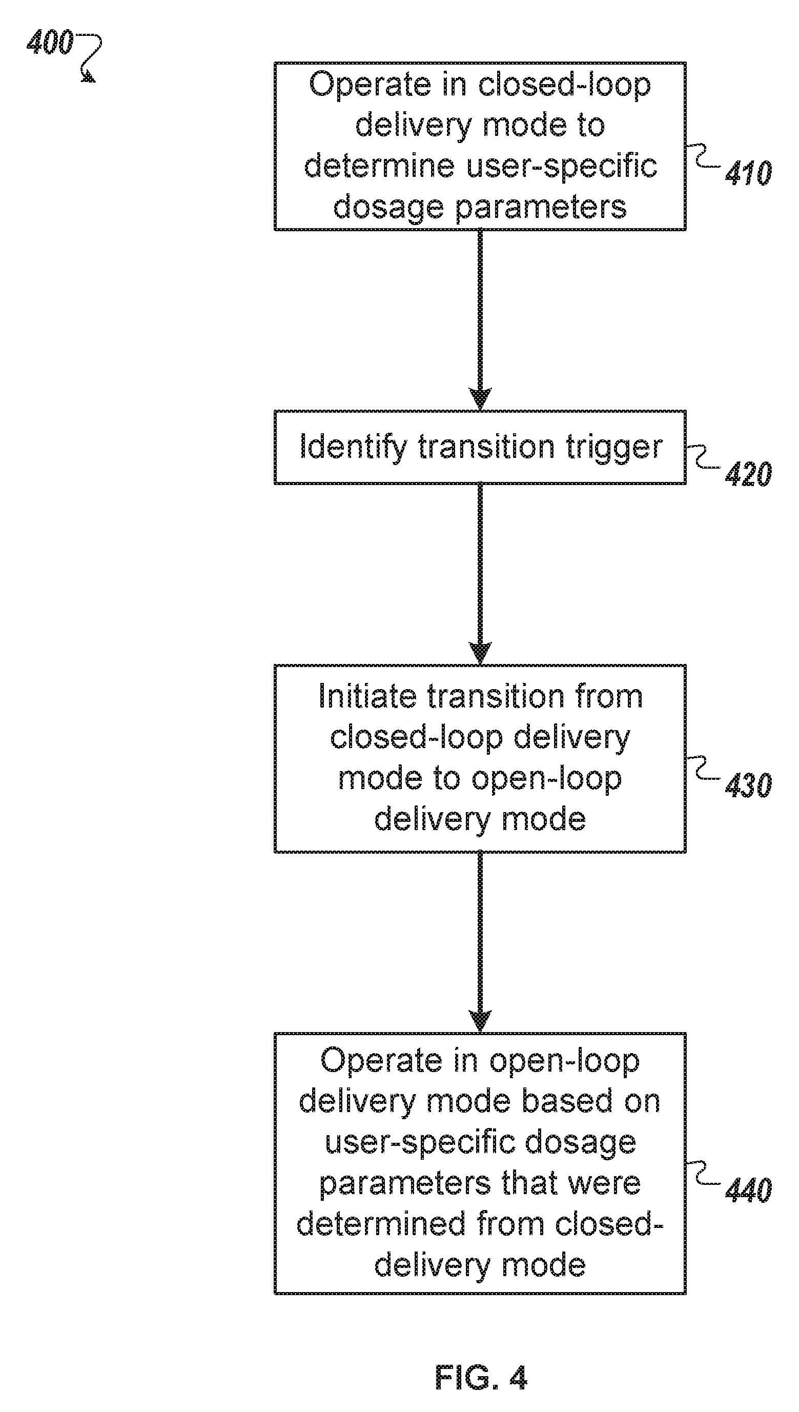
FIG. 4 is a flowchart of an example process for operating an infusion pump system according to multiple dosage delivery modes, in accordance with some embodiments.
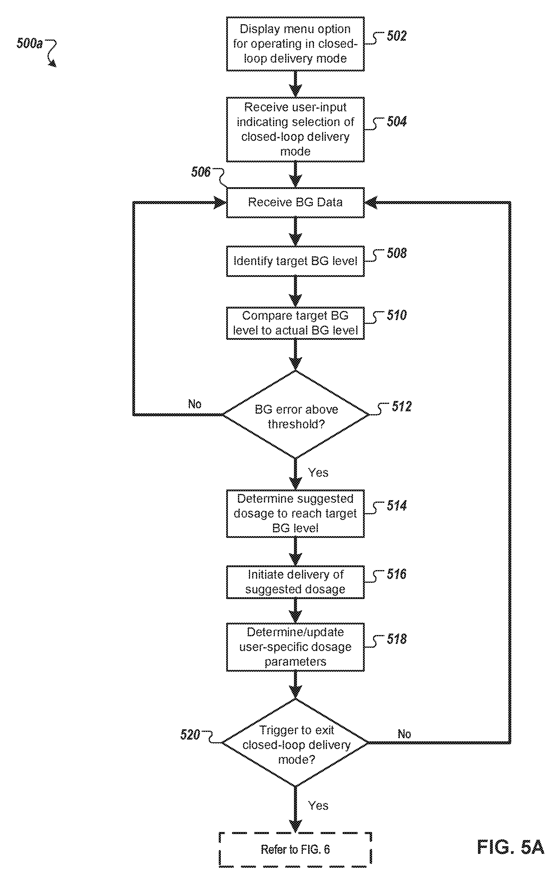
FIG. 5A is a flowchart of a first example process for operating an infusion pump system in a closed-loop delivery mode, in accordance with some embodiments.
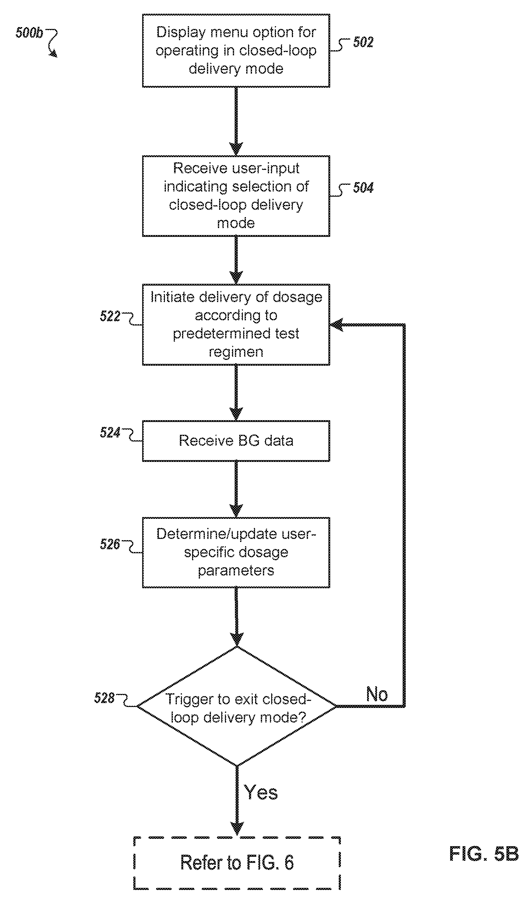
FIG. 5B is a flowchart of a second example process for operating an infusion pump system in a closed-loop delivery mode, in accordance with some embodiments.
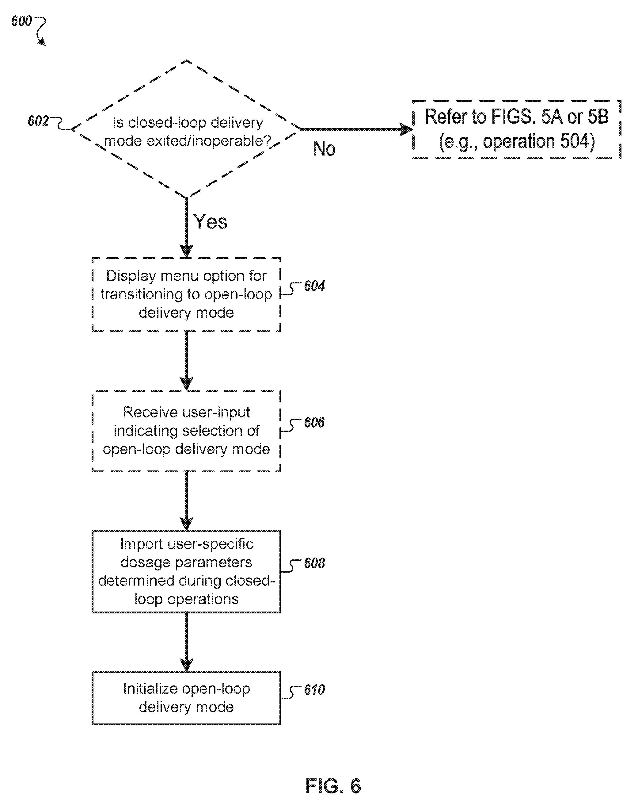
FIG. 6 is a flow chart of an example process for operating an infusion pump system to transition between a closed-loop delivery mode and an open-loop delivery mode, in accordance with some embodiments.
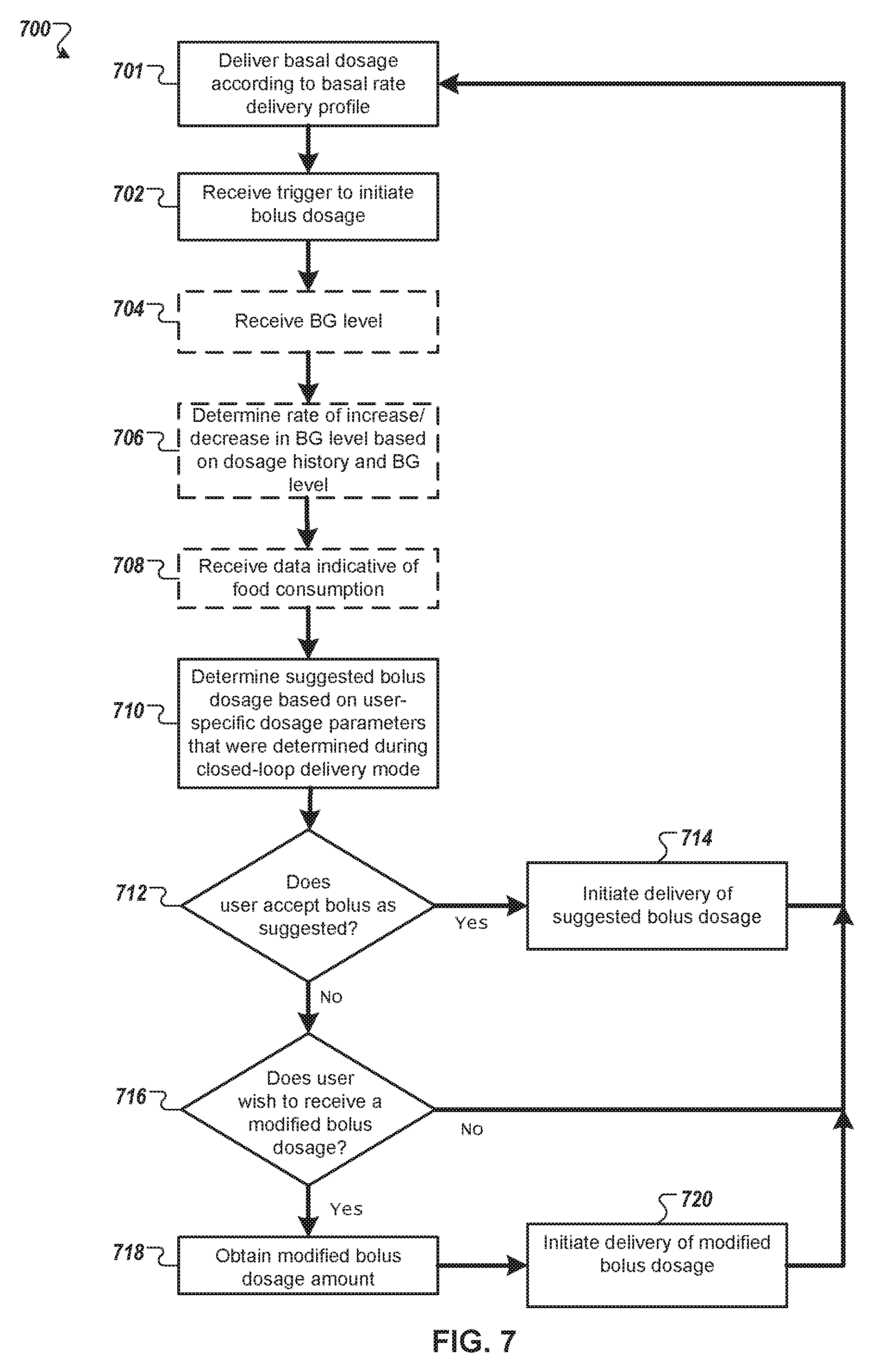
FIG. 7 is a flow chart of an example process for operating an infusion pump system in an open-loop delivery mode, in accordance with some embodiments.
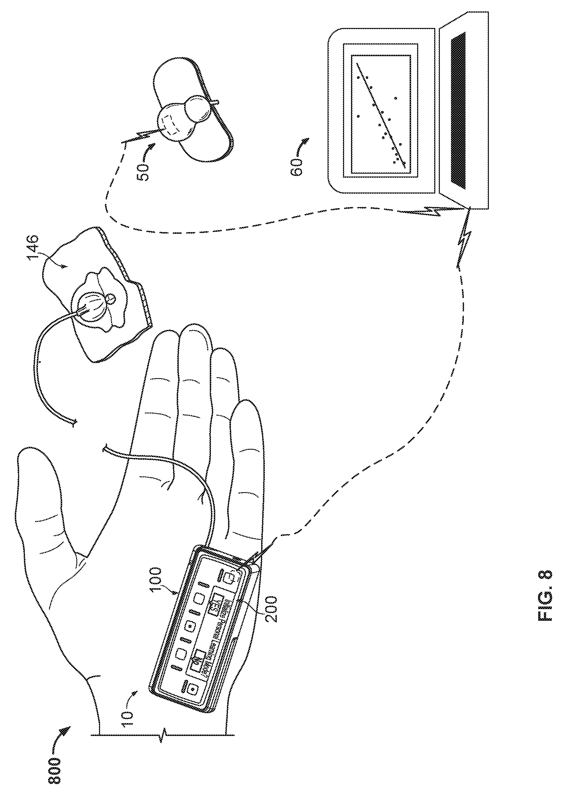
FIG. 8 is a perspective view of a second example infusion pump system, in accordance with some embodiments.
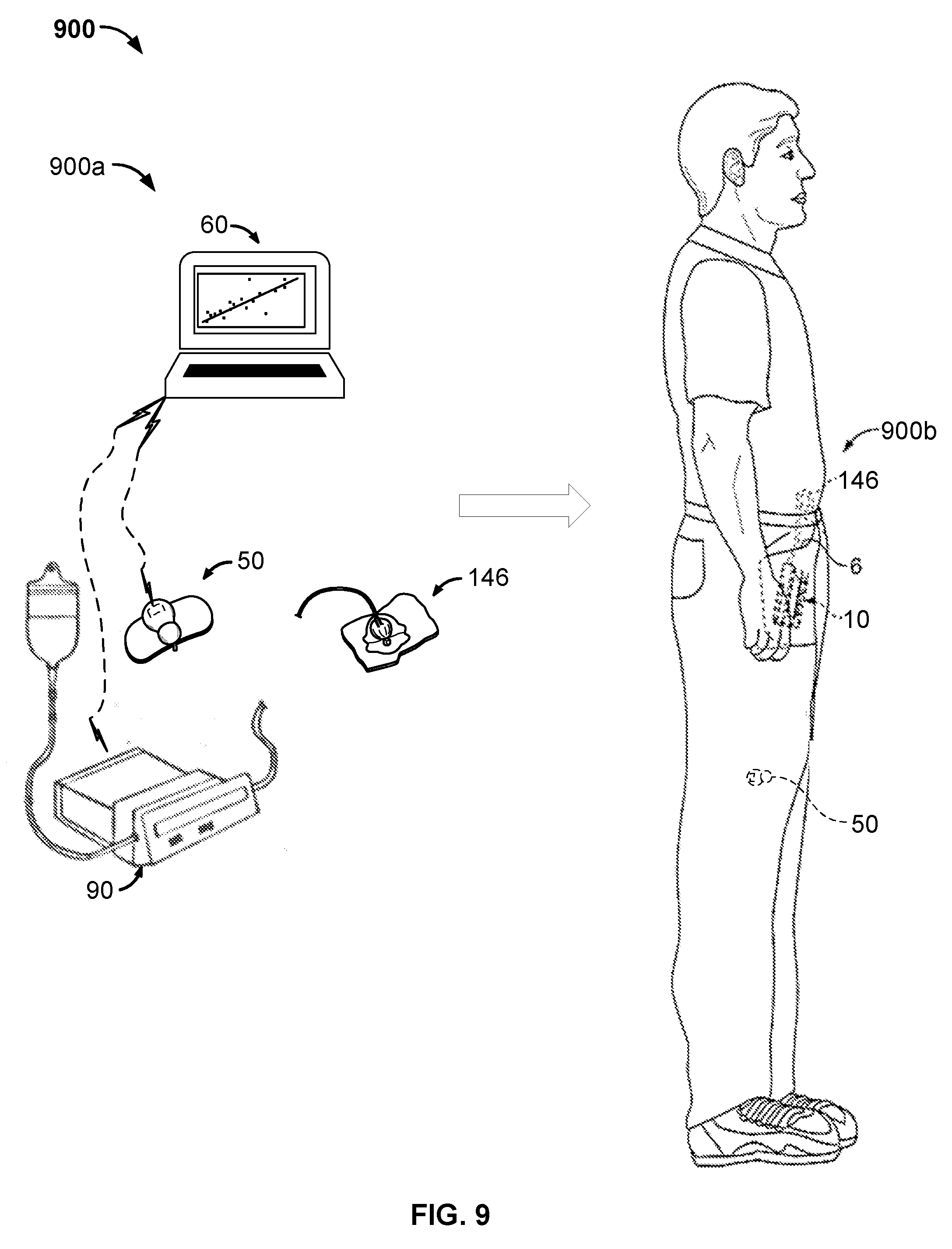
FIG. 9 is a perspective view of a third example infusion pump system, in accordance with some embodiments.
Like reference symbols in the various drawings may indicate like elements.
DETAILED DESCRIPTION OF ILLUSTRATIVE EMBODIMENTS
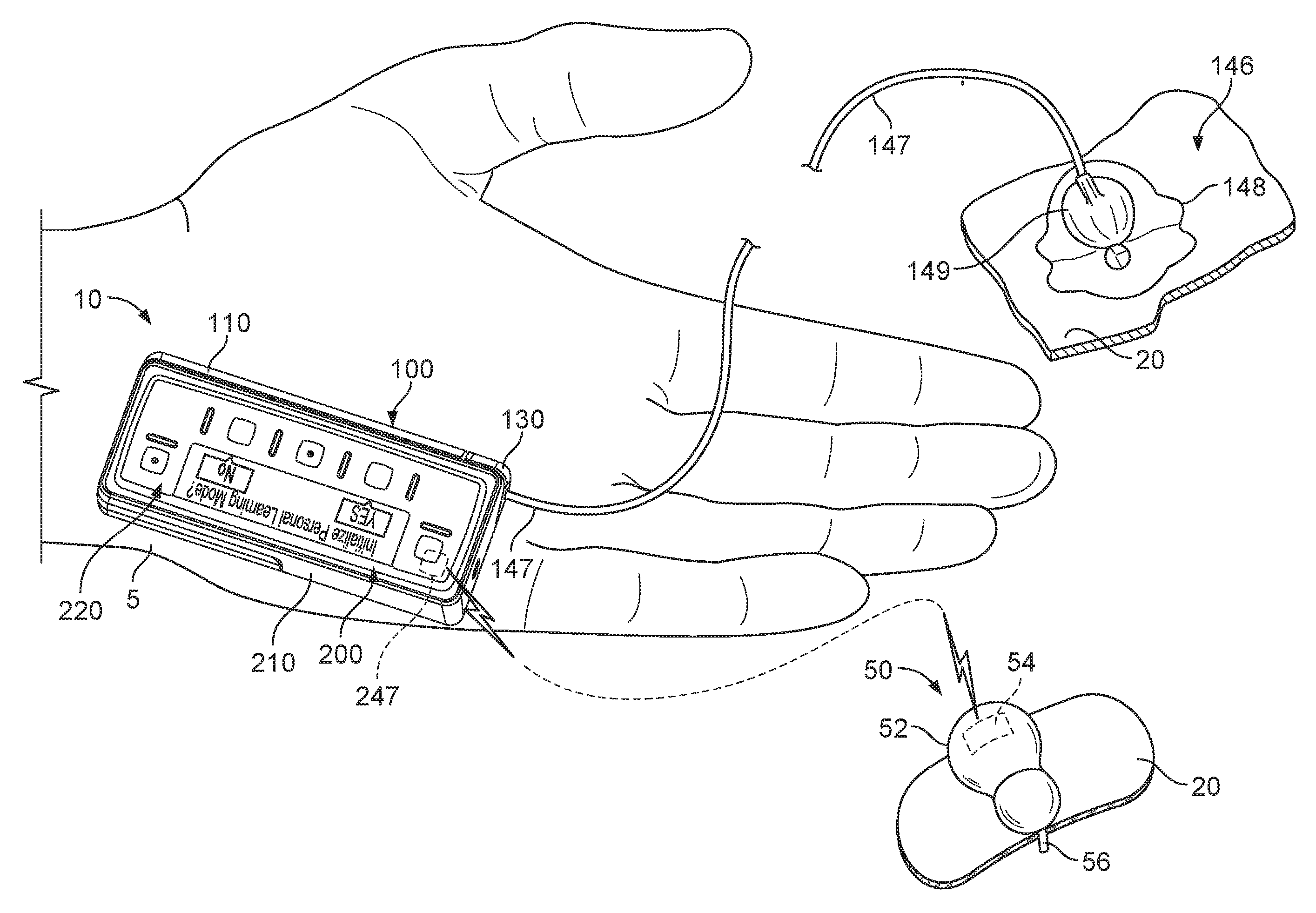
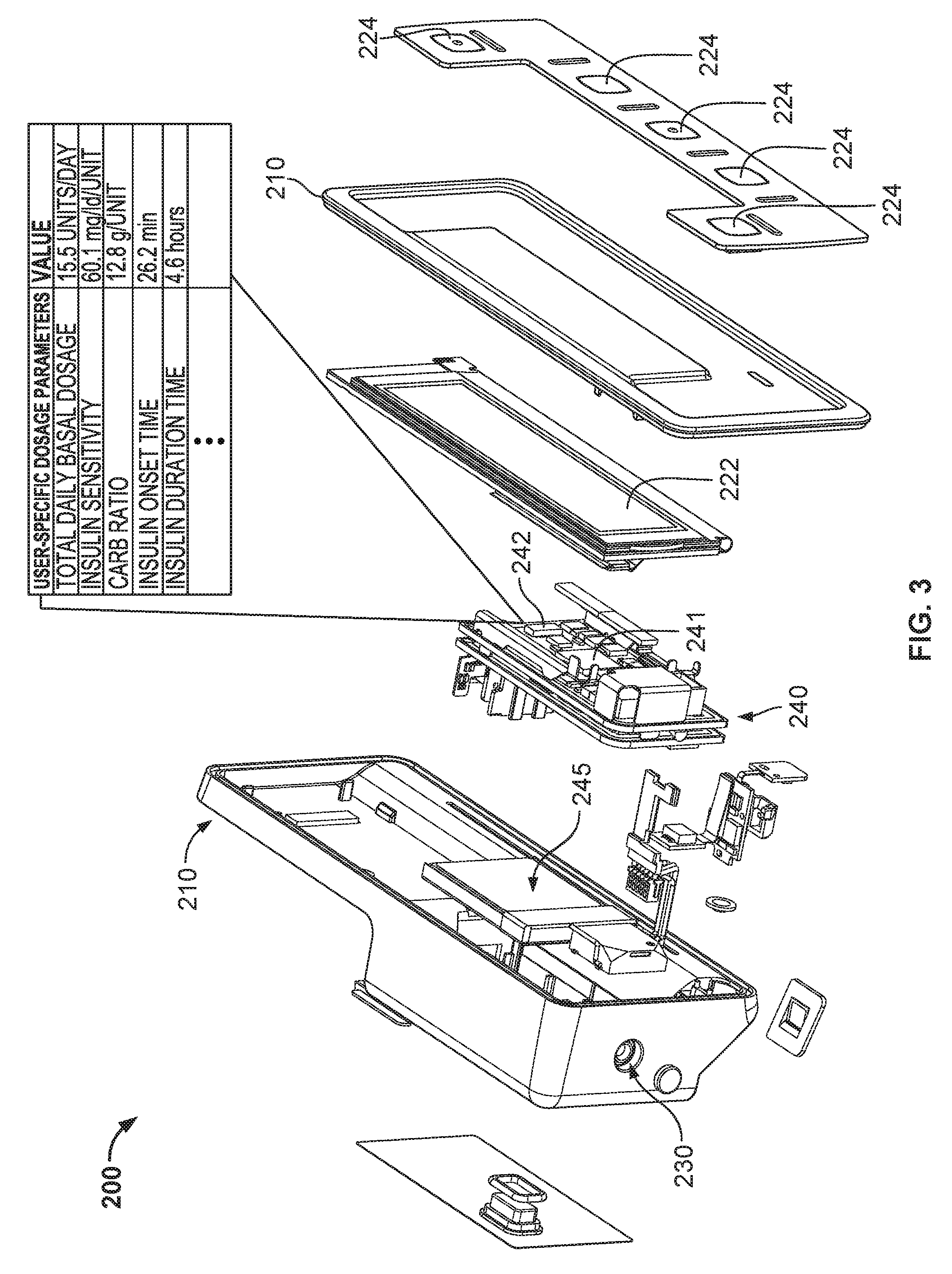
Referring to FIG. 1, some embodiments of an infusion pump system 1 can include a pump assembly 10 featuring a pump device 100 and a controller device 200. Optionally, the controller device 200 can be configured to releasably attach with the pump device 100. The controller device 200 can electrically communicate with the pump device 100 to control a drive system housed in the pump device 100 to dispense a medicine to a user (e.g., through a tube 147 of an infusion set 146 in this example). When the controller device 200 and the pump device 100 are assembled together, the user can (in some embodiments) conveniently wear the infusion pump system 1 on the user's skin under clothing, in a pouch clipped at the waist, or in the user's pocket while receiving the fluid dispensed from the pump device 100.
Briefly, in use, the pump device 100 in this embodiment is configured to removably attach to the controller device 200 in a manner that provides a secure fitting, an overall compact size, and a reliable electrical connection. For example, as described in more detail below in connection with FIG. 2, the controller device 200 can include a housing 210 having a number of features that mate with complementary features of the pump housing 110. In such circumstances, the controller device 200 can removably attach with the pump device 100 in a generally side-by-side configuration. The compact size permits the pump assembly 10 to be discrete and portable. The controller device 200 can receive user input for purposes of operating the infusion pump system 1. In some embodiments, as described further below in connection with FIGS. 4-7, the pump system 1 can be configured (e.g., appropriately designed and programmed) to operate in a personal settings learning mode in which the controller device 200 learns and stores one or more user-specific dosage parameters or other settings (e.g., the user's insulin sensitivity, the user's carb ratio, or other settings). For example, the controller device 200 can be configured to operate the infusion pump system 1 according to closed-loop delivery mode and an open-loop delivery mode. During operations under the closed-loop delivery mode, the controller device 200 is configured to determine and store one or more user-specific settings, such as a user's personal dosage parameters, which can be subsequently accessed during future closed-loop or open-loop operations (e.g., bolus dosage calculations and the like).
Still referring to FIG. 1, the infusion pump system 1 may optionally include a glucose monitoring device 50 in communication with the pump assembly 10 for the purpose of supplying data indicative of a user's blood glucose level to the controller device 200. In some embodiments, as described further below in connection with FIGS. 5A and 5B, the controller device 200 can utilize the data indicative of a user's blood glucose level during a closed-loop delivery mode to determine and/or update one or more user-specific dosage parameters. In some embodiments, as described further below in connection with FIG. 6, the controller device can also utilize the data indicative of a user's blood glucose level during an open-loop delivery mode, for example, to calculate a suggested bolus dosage based on the user-specific dosage parameters determined or updated during the closed-loop delivery mode.
The glucose monitoring device 50 can include a housing 52, a wireless communication device 54, and a sensor shaft 56. The wireless communication device 54 can be contained within the housing 52 and the sensor shaft 56 can extend outward from the housing 52. In use, the sensor shaft 56 can penetrate the skin 20 of a user to make measurements indicative of characteristics of the user's blood (e.g., the user's blood glucose level or the like). In response to the measurements made by the sensor shaft 56, the glucose monitoring device 50 can employ the wireless communication device 54 to transmit data to a corresponding wireless communication device 247 housed in the pump system 10. In some embodiments, the monitoring device 50 may include a circuit that permits sensor signals (e.g., data from the sensor shaft 56) to be communicated to the communication device 54. The communication device 54 can transfer the collected data to the controller device 200 (e.g., by wireless communication to the communication device 247). Alternatively, the monitoring device 50 can employ other methods of obtaining information indicative of a user's blood characteristics and transferring that information to the controller device 200. For example, an alternative monitoring device may employ a micropore system in which a laser porator creates tiny holes in the uppermost layer of a user's skin, through which interstitial glucose is measured using a patch. In the alternative, the monitoring device can use iontophoretic methods to non-invasively extract interstitial glucose for measurement. In other examples, the monitoring device can include non-invasive detection systems that employ near IR, ultrasound or spectroscopy, and particular embodiments of glucose-sensing contact lenses. Invasive methods involving optical means of measuring glucose could also be added. In yet another example, the monitoring device can include an optical detection instrument that is inserted through the skin for measuring the user's glucose level.
Furthermore, it should be understood that in some alternative embodiments, the monitoring device 50 can be in communication with the controller device 200 via a wired connection. In other embodiments of the infusion pump system 1, one or more test strips (e.g., blood test strips) containing a sample of the user's blood can be inserted into a strip reader portion of the pump system 1 to be tested for characteristics of the user's blood. Alternatively, the test strips (e.g., glucose test strips) containing a sample of the user's blood can be inserted into a glucose meter device (not shown in FIG. 1), which then analyzes the characteristics of the user's blood and communicates the information (via a wired or wireless connection) to the controller device 200. In still other embodiments, characteristics of the user's blood glucose information can be entered directly into the pump system 10 via a user interface 220 on the controller device 200.
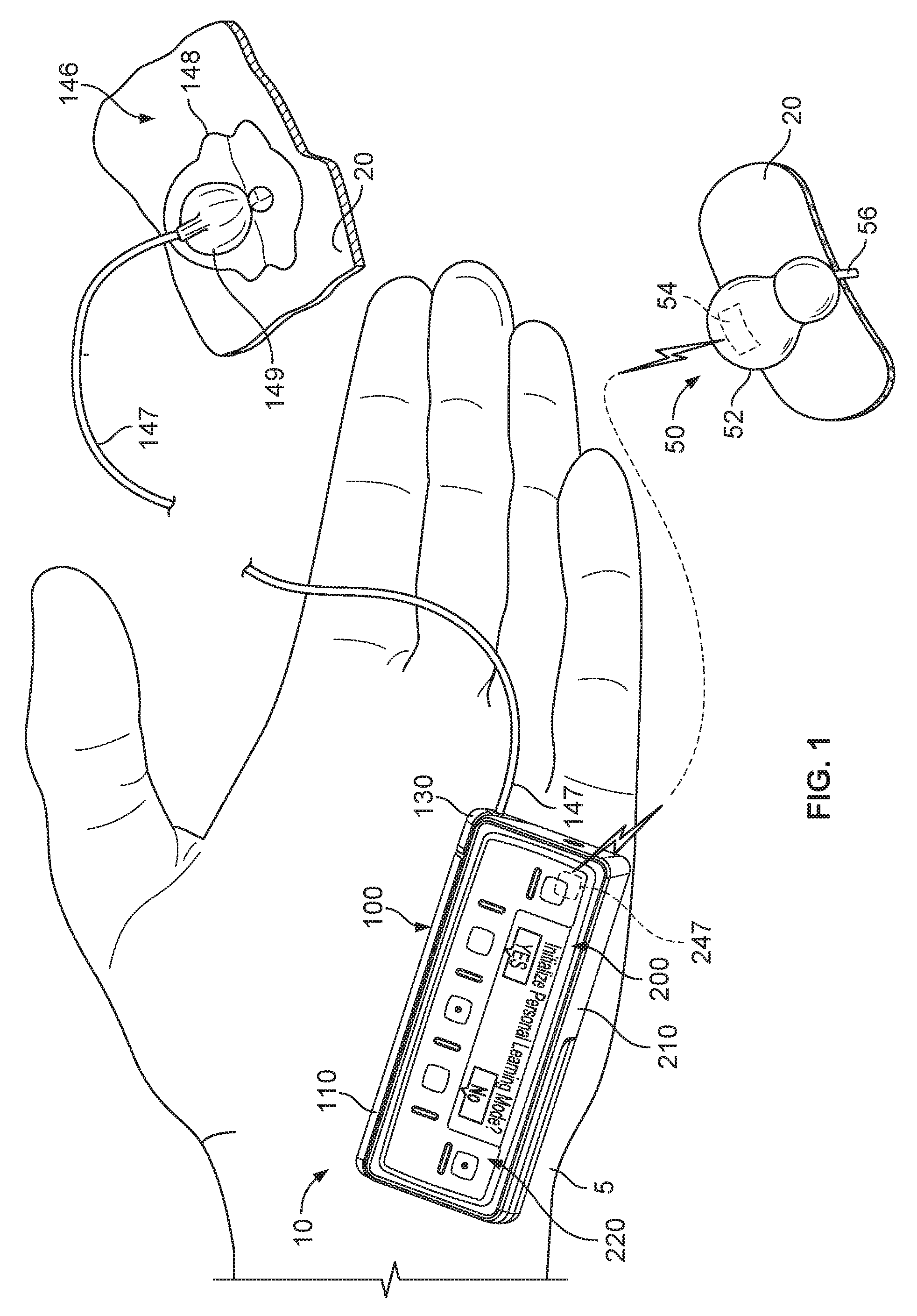
Referring now to FIG. 2, the pump device 100 in this embodiment includes a housing structure 110 that defines a cavity 116 in which a fluid cartridge 120 can be received. The pump device 100 also can include a cap device 130 to retain the fluid cartridge 120 in the cavity 116 of the housing structure 110. The pump device 100 can include a drive system (not shown) that advances a plunger 125 in the fluid cartridge 120 so as to dispense fluid therefrom. In this embodiment, the controller device 200 communicates with the pump device 100 to control the operation of the drive system. Optionally, the controller device 200 may be configured as a reusable component that provides electronics and a user interface to control the operation of the pump device 100. In such circumstances, the pump device 100 can be a disposable component that is disposed of after a single use. For example, the pump device 100 can be a "one time use" component that is thrown away after the fluid cartridge 120 therein is exhausted. Thereafter, the user can removably attach a new pump device (having a new fluid cartridge) to the reusable controller device 200 for the dispensation of fluid from a new fluid cartridge. Accordingly, the user is permitted to reuse the controller device 200 (which may include complex or valuable electronics, as well as a rechargeable battery) while disposing of the relatively low-cost pump device 100 after each use. Such a pump assembly 10 can provide enhanced user safety as a new pump device (and drive system therein) is employed with each new fluid cartridge.
The pump assembly 10 can be a medical infusion pump assembly that is configured to controllably dispense a medicine from the cartridge 120. As such, the fluid cartridge 120 can contain a medicine 126 to be infused into the tissue or vasculature of a targeted individual, such as a human or animal patient. For example, the pump device 100 can be adapted to receive a fluid cartridge 120 in the form of a carpule that is preloaded with insulin or another medicine for use in the treatment of Diabetes (e.g., Byetta.RTM., Symlin.RTM., or others). Such a cartridge 120 may be supplied, for example, by Eli Lilly and Co. of Indianapolis, Ind. Other examples of medicines that can be contained in the fluid cartridge 120 include: pain relief drugs, hormone therapy, blood pressure treatments, anti-emetics, osteoporosis treatments, or other injectable medicines. The fluid cartridge 120 may have other configurations. For example, the fluid cartridge 120 may comprise a reservoir that is integral with the pump housing structure 110 (e.g., the fluid cartridge 120 can be defined by one or more walls of the pump housing structure 110 that surround a plunger to define a reservoir in which the medicine is injected or otherwise received).
In some embodiments, the pump device 100 can include one or more structures that interfere with the removal of the fluid cartridge 120 after the fluid cartridge 120 is inserted into the cavity 116. For example, the pump housing structure 110 can include one or more retainer wings (not shown) that at least partially extend into the cavity 116 to engage a portion of the fluid cartridge 120 when the fluid cartridge 120 is installed therein. Such a configuration may facilitate the "one-time-use" feature of the pump device 100. In some embodiments, the retainer wings can interfere with attempts to remove the fluid cartridge 120 from the pump device 100, thus ensuring that the pump device 100 will be discarded along with the fluid cartridge 120 after the fluid cartridge 120 is emptied, expired, or otherwise exhausted. In another example, the cap device 130 can be configured to irreversibly attach to the pump body 110 so as to cover the opening of the cavity 116. For example, a head structure of the cap device 130 can be configured to turn so as to threadably engage the cap device 130 with a mating structure along an inner wall of the cavity 116, but the head structure may prevent the cap device from turning in the reverse direction so as to disengage the threads. Accordingly, the pump device 100 can operate in a tamper-resistant and safe manner because the pump device 100 can be designed with a predetermined life expectancy (e.g., the "one-time-use" feature in which the pump device is discarded after the fluid cartridge 120 is emptied, expired, or otherwise exhausted).
Still referring to FIG. 2, the controller device 200 can be removably attached to the pump device 100 so that the two components are mechanically mounted to one another in a fixed relationship. In some embodiments, such a mechanical mounting can also form an electrical connection between the removable controller device 200 and the pump device 100. For example, the controller device 200 can be in electrical communication with a portion of the drive system (show shown) of the pump device 100. In some embodiments, the pump device 100 can include a drive system that causes controlled dispensation of the medicine or other fluid from the cartridge 120. In some embodiments, the drive system incrementally advances a piston rod (not shown) longitudinally into the cartridge 120 so that the fluid is forced out of an output end 122. A septum 121 at the output end 122 of the fluid cartridge 120 can be pierced to permit fluid outflow when the cap device 130 is connected to the pump housing structure 110. For example, the cap device 130 may include a penetration needle that punctures the septum 121 during attachment of the cap device to the housing structure 110. Thus, when the pump device 100 and the controller device 200 are mechanically attached and thereby electrically connected, the controller device 200 communicates electronic control signals via a hardwire-connection (e.g., electrical contacts or the like) to the drive system or other components of the pump device 100. In response to the electrical control signals from the controller device 200, the drive system of the pump device 100 causes medicine to incrementally dispense from the fluid cartridge 120. Power signals, such as signals from a battery (not shown) of the controller device 200 and from the power source (not shown) of the pump device 100, may also be passed between the controller device 200 and the pump device 100.
Still referring to FIG. 2, the controller device 200 can include a user interface 220 that permits a user to monitor and actively control the operation of the pump device 100. In some embodiments, the user interface 220 can include a device 222 and one or more user-selectable buttons (e.g., several buttons 224 are shown in the embodiment of FIGS. 1-2). The display device 222 can include an active area in which numerals, text, symbols, images, or a combination thereof can be displayed. For example, the display device 222 can be used to communicate a number of settings or menu options for the infusion pump system 1 (FIG. 1). In this embodiment, the user may press one or more of the buttons to shuffle through a number of menus or program screens that show particular operational modes (e.g., closed-loop delivery mode and open-loop delivery mode), settings (e.g., user-specific dosage parameters) and data (e.g., review data that shows the medicine dispensing rate, the total amount of medicine dispensed in a given time period, the amount of medicine scheduled to be dispensed at a particular time or date, the approximate amount of medicine remaining in the cartridge 120, or the like). In some embodiments, the user can adjust the modes and/or settings, or otherwise program the controller device 200 by pressing one or more buttons 224 of the user interface 220. For example, the user may press one or more of the buttons to change the operation of the infusion pump system 1 from a closed-loop delivery mode to an open-loop delivery mode. In some implementations, the display device 222 may also be used to communicate information regarding remaining battery life.
The pump assembly 10 can be configured to be portable and can be wearable and concealable. For example, a user can conveniently wear the pump assembly 10 on the user's skin (e.g., skin adhesive) underneath the user's clothing or carry the pump device 100 in the user's pocket (or other portable location) while receiving the medicine dispensed from the pump device 100. The pump assembly 10 depicted in FIG. 1 as being held in a user's hand 5 so as to illustrate its size in accordance with some embodiments.
This embodiment of the pump assembly 10 is compact so that the user can wear the portable pump assembly 10 (e.g., in the user's pocket, connected to a belt clip, adhered to the user's skin, or the like) without the need for carrying and operating a separate module. In such embodiments, the cap device 130 of the pump device 100 can be configured to mate with an infusion set 146. In general, the infusion set 146 can be a tubing system that connects the pump assembly 10 to the tissue or vasculature of the user (e.g., to deliver medicine into the tissue or vasculature under the user's skin). The infusion set 146 can include a flexible tube 147 that extends from the pump device 100 to a subcutaneous cannula 149 that may be retained by a skin adhesive patch (not shown) that secures the subcutaneous cannula 149 to the infusion site. The skin adhesive patch can retain the infusion cannula 149 in fluid communication with the tissue or vasculature of the user so that the medicine dispensed through the tube 147 passes through the cannula 149 and into the user's body. The cap device 130 can provide fluid communication between the output end 122 (FIG. 2) of the fluid cartridge 120 and the tube 147 of the infusion set 146.
In some embodiments, the pump assembly 10 can be pocket-sized so that the pump device 100 and controller device 200 can be worn in the user's pocket or in another portion of the user's clothing. In some circumstances, the user may desire to wear the pump assembly 10 in a more discrete manner. Accordingly, the user can pass the tube 147 from the pocket, under the user's clothing, and to the infusion site where the adhesive patch can be positioned. As such, the pump assembly 10 can be used to deliver medicine to the tissues or vasculature of the user in a portable, concealable, and discrete manner.
In some embodiments, the pump assembly 10 can be configured to adhere to the user's skin directly at the location in which the skin is penetrated for medicine infusion. For example, a rear surface of the pump device 100 can include a skin adhesive patch so that the pump device 100 can be physically adhered to the skin of the user at a particular location. In these embodiments, the cap device 130 can have a configuration in which medicine passes directly from the cap device 130 into an infusion cannula 149 that is penetrated into the user's skin. In some examples, the user can temporarily detach the controller device 200 (while the pump device 100 remains adhered to the skin) so as to view and interact with the user interface 220.
In some embodiments, the pump assembly 10 can operate (during an open-loop mode, for example) to deliver insulin to the user by basal dosages, selected bolus dosages, or a combination thereof. A basal rate of insulin can be delivered in an incremental manner (e.g., dispense 0.25 U every fifteen minutes for a rate of 1.0 U per hour) to help maintain the user's blood glucose level within a targeted range during normal activity, when the user is not consuming food items. The user may select one or more bolus deliveries, for example, to offset the blood glucose effects caused by food intake, to correct for an undesirably high blood glucose level, to correct for a rapidly increasing blood glucose level, or the like. In some circumstances, the basal rate delivery pattern may remain at a substantially constant rate for a long period of time (e.g., a first basal dispensation rate for a period of hours in the morning, and a second basal dispensation rate for a period of hours in the afternoon and evening). In contrast, the bolus dosages can be more frequently dispensed based on calculations made by the controller device 200. For example, the controller device 200 can determine that the user's blood glucose level is rapidly increasing (e.g., by interpreting data received from the glucose monitoring device 50) and can administer appropriate bolus dosage of insulin to correct for the rapid increase in blood glucose level. In another example, the user can request (via the user interface 220) that the controller device 200 calculate and suggest a bolus dosage based, at least in part, on a proposed meal that the user plans to consume.
The basal and bolus insulin dispensed into the user's body may act over a period of time to control the user's blood glucose level. As such, the user can benefit from the embodiments of the infusion pump system 1 that can take into account different circumstances and information when determining a suggested amount of a basal or bolus dosage. For example, the controller device 200 may be triggered to calculate a suggested bolus dosage in response to the user's food intake. When calculating the bolus dosage, however, the user may benefit if the controller device 200 employed one or more user-specific dosage parameters that reflect the user's physiological response to insulin. In some embodiments, the controller device 200 can employ the user-specific dosage parameters in combination with data indicative of the user's blood glucose level, historical food intake data previously submitted by the user, the user's insulin load, and the like to provide an accurate dosage calculation. Exemplary information that can be derived from the user's blood glucose information that can be used by the controller device 200 in determining a bolus dosage can include the user's current blood glucose level, the rate of change in the user's blood glucose level, the 2.sup.nd derivative of the user's blood glucose data, the shape and/or appearance of the user's blood glucose curve, or the like. In some embodiments, the controller device 200 can use information from previously entered meals and previously delivered insulin dosages when calculating a suggested bolus dosage. In these embodiments, information regarding previously entered meals and previously delivered insulin dosages from 12 hours or more (e.g., 24 hours, 12 hours, 8 hours, 6 hours, 0.5 hours, or the like) can be used in the bolus dosage calculations.
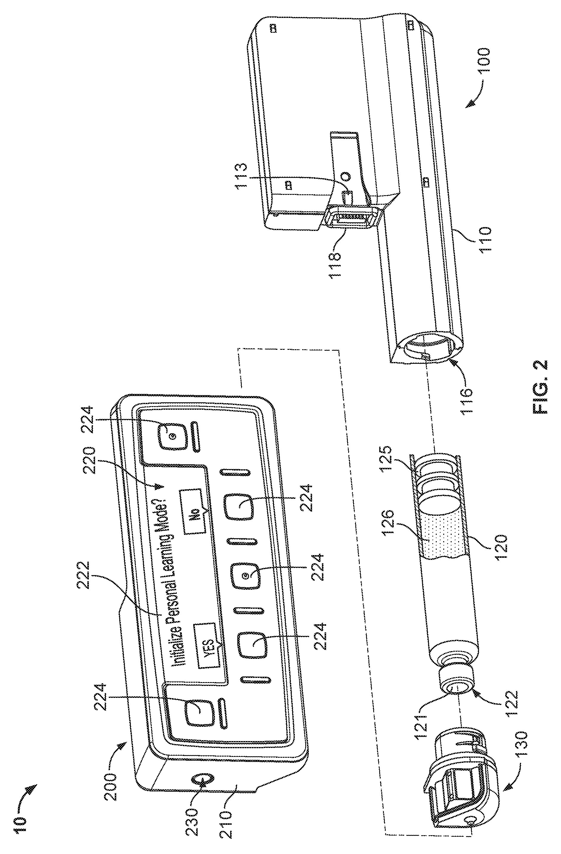
Referring now to FIG. 3, the controller device 200 (shown in an exploded view) houses a number of components that can be reused with a series of successive pump devices 100. In particular, the controller device 200 can include control circuitry 240 and a rechargeable battery pack 245, each arranged in the controller housing 210. The rechargeable battery pack 245 may provide electrical energy to components of the control circuitry 240, other components of the controller device (e.g., the display device 222 and other user interface components, sensors, or the like), or to components of the pump device 100. The control circuitry 240 may be configured to communicate control or power signals to the drive system of the pump device 100, or to receive power or feedback signals from the pump device 100.
The control circuitry 240 of the controller device 200 can include one or more microprocessors 241 configured to execute computer-readable instructions stored on one or more memory devices 242 so as to achieve any of the control operations described herein. At least one memory device 242 of the control circuitry may be configured to store a number of user-specific dosage parameters. One or more user-specific dosage parameters may be input by a user via the user interface 220. Further, as described further below in connection with FIGS. 5A and 5B, various user-specific dosage parameters can be automatically determined and/or updated by control operations implemented by the control circuitry 240 of the controller device 200. For example, the control circuitry 240 can determine and/or update one or more user-specific dosage parameters while the infusion pump system 1 operates in a closed-loop delivery mode. Whether determined automatically or received via the user interface 220, the control circuitry 240 can cause the memory device 242 to store the user-specific dosage parameters for future use during operations according to a closed-loop or open-loop delivery mode.
Such user-specific dosage parameters may include, but are not limited to, one or more of the following: insulin sensitivity (e.g., in units of mg/dL/insulin unit), carbohydrate ratio (e.g., in units of g/insulin unit), insulin onset time (e.g., in units of minutes and/or seconds), insulin on board duration (e.g., in units of minutes and/or seconds), and basal rate profile (e.g., an average basal rate or one or more segments of a basal rate profile expressed in units of insulin unit/hour). Also, the control circuitry 240 can cause the memory device 242 to store any of the following parameters derived from the historical pump usage information: dosage logs, average total daily dose, average total basal dose per day, average total bolus dose per day, a ratio of correction bolus amount per day to food bolus amount per day, amount of correction boluses per day, a ratio of a correction bolus amount per day to the average total daily dose, a ratio of the average total basal dose to the average total bolus dose, average maximum bolus per day, and a frequency of cannula and tube primes per day. To the extent these aforementioned dosage parameters or historical parameters are not stored in the memory device 241, the control circuitry 240 can be configured to calculate any of these aforementioned dosage parameters or historical parameters from other data stored in the memory device 241 or otherwise input via the user interface 220.
The user interface 220 of the controller device 200 can include input components and/or output components that are electrically connected to the control circuitry 240. For example, the user interface 220 can include the display device 222 having an active area that outputs information to a user and buttons 224 that the user can use to provide input. Here, the display device 222 can be used to communicate a number of settings (e.g., user-specific dosage parameters) or menu options (e.g., options for switching between closed-loop and open-loop delivery modes) for the infusion pump system 1. In some embodiments, the control circuitry 240 can receive input commands from a user's button selections and thereby cause the display device 222 to output a number of menus or program screens that show particular settings and data (e.g., review data that shows the medicine dispensing rate, the total amount of medicine dispensed in a given time period, the amount of medicine scheduled to be dispensed at a particular time or date, the approximate amount of medicine remaining the cartridge 120, the amount of battery life remaining, or the like). The control circuitry 240 can be programmable to cause the control circuitry 240 to change any one of a number of settings or modes of operation for the infusion pump system 1. In some embodiments, the control circuitry 240 can include a cable connector (e.g., a USB connection port or another data cable port) that is accessible on an external portion of the controller housing 210. As such, a cable can be connected to the control circuitry 240 to upload or download data or program settings to the control circuitry.
Referring now to FIG. 4, the control circuitry of an infusion pump system can implement a process 400 of operating the infusion pump system according to multiple dosage delivery modes. Such a process 400, for example, can be implemented by the control circuitry 240 housed in the controller device 200 of an infusion pump assembly 10 (FIGS. 1-3). However, the description here not necessarily limited to any particular infusion pump system with respect to process 400, and the process 400 may be implemented using, for example, an infusion pump system in which the control circuitry and drive system components are housed together in a reusable pump unit. In another alternative example, the process 400 may be implemented using a remote device (a specially programmed smart phone device) that wireless communicates with an infusion pump system and is configured to calculate various user-specific dosage parameters during the closed-loop delivery mode.
In operation 410, the control circuitry operates the infusion pump system in a closed-loop delivery mode to determine one or more user-specific dosage parameters (see, e.g., FIGS. 5A and 5B). In the closed-loop delivery mode, the control circuitry can operate the medical device to autonomously (e.g., without user-interaction) alter the dispensation of medication to a user based upon a sensed physiological condition. For example, if the infusion pump system is dispensing insulin, closed-loop operations facilitated by the control circuitry may cause the infusion pump system to imitate a pancreatic beta cell (see FIG. 5A) so that the insulin dispensation is adjusted according to increases or decreases in the user's blood glucose level. This type of closed-loop control delivery mode can be executed by the control circuitry via any suitable control algorithm (e.g., a proportional-integral-derivative (PID), fuzzy logic, or model predictive control algorithm). Further, in some examples, the control circuitry can facilitate closed-loop operations that are consistent with a test regimen (see FIG. 5B). During such closed-loop operations, the control circuitry can monitor one or more sensor signals indicative of the user's response to the dispensation of medication. The sensory feedback signals can be used to implement a feedback control loop (see FIG. 5A) and/or to determine one or more user-specific dosage parameters. In one or more embodiments featuring an insulin-dispensing infusion pump system, suitable feedback signals may include, but are not limited to: physiological signals such as blood glucose data, activity data (e.g., heart rate, EKG heart activity, EMG muscle activity, respiration activity, etc.), blood pressure, and the like, glucagon delivery data, and food intake data. As noted above, in such embodiments, user-specific dosage parameters may include, but are not limited to: insulin sensitivity (e.g., in units of mg/dL/insulin unit), carbohydrate ratio (e.g., in units of g/insulin unit), insulin onset time (e.g., in units of minutes and/or seconds), insulin on board duration (e.g., in units of minutes and/or seconds), and basal rate profile (e.g., an average basal rate or one or more segments of a basal rate profile expressed in units of insulin unit/hour).
In some embodiments, a user-specific dosage parameter can be determined as a function time and/or as a function of a monitored sensory feedback signal. As one non-limiting example, a series of multiple insulin sensitivities can be determined based on the time of day and/or based on the user's blood glucose level. The user-specific dosage parameters can be determined using any suitable mathematical technique. For example, in some embodiments, the control circuitry may employ a predefined data model (e.g., an empirical or statistical model expressed in an algebraic formula) and/or a regression analysis (e.g., a single or multi-variable regression analysis) to determine the parameters. The scope of the present disclosure is not limited to any particular process, algorithm, or technique for determining the various user-specific dosage parameters described herein.
In operation 420, the control circuitry identifies a transition trigger signaling a change in the dosage delivery mode (see, e.g., FIG. 6). In one example, the user may access a menu option displayed by the infusion pump system and press a user interface button that triggers the user's requested change from the closed-loop delivery mode to an open-loop delivery mode. In another example, a transition trigger may arise upon expiration of a predetermined time period for operating in the closed-loop delivery mode.
In operation 430, the control circuitry initiates a transition from the closed-loop delivery mode to an open-loop delivery mode (see e.g., FIG. 6). For example, the infusion pump system may cease adjustments of the insulin delivery in response to changes in the user's glucose feedback data, and instead may prompt the user (via the user interface) to confirm that insulin delivery will return to a basal profile delivery according the open-loop delivery mode. In operation 440, the control circuitry operates the medical device in the open-loop delivery mode based on the user-specific dosage parameters determined during operations in the closed-loop delivery mode (see, e.g., FIG. 7). In the open-loop delivery mode, the control circuitry can operate the infusion pump system to dispense medication according to a selected basal delivery pattern and according to user-initiated bolus deliveries. For example, the user may manually input food intake data or blood glucose data and the control circuitry may calculate a suggested bolus dosage of insulin in response. As another example, the control circuitry may monitor a continuous glucose sensor on the user and provide an alert to the user when his/her blood glucose level suggests that a correction bolus dosage is needed. In some embodiments, the suggested bolus dosage is calculated based on the user-specific dosage parameters that were determined (and stored in the memory) during the closed-loop delivery mode.
FIG. 5A depicts a first example process 500a executable by the controller device 200 for operating the infusion pump system 1 in a closed-loop delivery mode to determine one or more user-specific dosage parameters. In operation 502, the controller device causes a menu option for operating in a closed-loop delivery mode to be displayed to the user via the display device 222 (see FIGS. 1 and 2). The user can accept or decline the option by selecting the appropriate user-interface buttons 224. In operation 504, the controller device 200 can receive user-input indicating selection of the closed-loop delivery mode. For example, the user can select the user interface button 224 corresponding to "YES" on the display screen presenting the menu option (see FIGS. 1 and 2).
In operation 506, the controller device 200 initiates an iterative sequence of operations that facilitate the closed-loop delivery of medication (e.g., insulin) by receiving blood glucose data. As described above, blood glucose data can be received from a glucose monitoring device 50 in wireless communication with the pump assembly 10 (or received from a blood glucose test strip reader). In operation 508, the controller device 200 identifies a target blood glucose level. For example, one or more target blood glucose levels may be stored in memory device 242 of the control circuitry 240. The target blood glucose levels may correspond to one or more monitored sensory feedback signals. For instance, the target blood glucose level may vary according to the user's food intake and/or physiological status. As one example, the member device 242 stores data indicating at least a fasting target blood glucose level and a postprandial target blood glucose level. In some embodiments, a target blood glucose level can be expressed as a range. In some embodiments, the target blood glucose levels can be manually submitted to the controller device 200 via the user interface 220. In some embodiments, the target blood glucose levels can be determined statistically or empirically by the controller device 200 as a user-specific dosage parameter based on previous iterations of a closed-loop delivery scheme. In operation 510, the controller device 200 compares the user's actual blood glucose level (as indicated by the received blood glucose data) to the identified target blood glucose level to ascertain a blood glucose error. In operation 512, the controller device determines whether the blood glucose error is above a predetermined threshold. In operation 514, if the controller device 200 concludes that the actual blood glucose error is above a predetermined threshold (512), a correction dosage to correct the blood glucose error is determined. Otherwise (512), the controller device 200 returns to operation 506 to await the receipt of further blood glucose data. In some embodiments, the correction dosage is determined via suitable PID control calculations, fuzzy logic control calculations, and/or model predictive control calculations. In operation 516, the controller device 200 initiates delivery of the correction dosage. For example, as described above, the controller device 200 can issue one or more electronic control signals to the drive system of the pump device 100 to cause the dispensation of the correction bolus.
In operation 518, the controller device 200 determines (including determining a new value or updating a previously stored value) one or more user-specific dosage parameters (e.g., insulin sensitivity, carbohydrate ratio, insulin onset time, insulin on board duration, and basal rate profile). For example, the controller device 200 may initially calculate the dosage parameters after one or more iterations of the closed-loop delivery scheme and continue to update the dosage parameters during future iterations. Alternatively, one or more default dosage parameters may be manually input via the user interface 220, and subsequently updated during the closed-loop delivery mode. In some embodiments, the user-specific dosage parameters can be determined or updated based on historical sensory feedback data (e.g., historical blood glucose data) and historical pump-usage data generated during the closed-loop delivery operations. As noted above, the user-specific dosage parameters can be determined using any suitable mathematical technique (e.g., a predefined data model and/or a regression analysis). As one example, a regression analysis approximating the relationship between the correction dosage (refer to operation 516, described above) and blood glucose level can be used to determine an insulin sensitivity parameter that is specific to the user (because various users will respond differently to correction dosages of insulin).
In operation 520, the controller device 200 can detect a trigger to exit the closed-loop delivery mode. In one example, the user may access a menu option displayed by the controller 200 and press a user interface button 224 that triggers the user's requested change from the closed-loop delivery mode to an open-loop delivery mode. In another example, a transition trigger may arise upon expiration of a predetermined time period for operating in the closed-loop delivery mode. If the controller device 200 detects a trigger to exit the closed-loop delivery mode (520), it initiates a transition sequence (see FIG. 6). Otherwise (520), the controller device 200 returns to operation 506 to await the receipt of further blood glucose data (and operations under the closed-loop delivery mode).
FIG. 5B depicts a second example process 500b executable by the controller device 200 for operating the infusion pump system 1 in a closed-loop delivery mode to determine one or more user-specific dosage parameters. Similar to the example process 500a of FIG. 5A, in operation 502, a menu option for operating in a closed-loop delivery mode is displayed to the user via the display device 222 (see FIGS. 1 and 2). The user can accept or decline the option by selecting the appropriate user-interface buttons 224. In operation 504, the controller device 200 receives user-input indicating selection of the closed-loop delivery mode (e.g., the user can select the user interface button 224 corresponding to the "YES" option on the display device 222).
In operation 522, the controller device 200 initiates the delivery of at least one medicine dosage (e.g., a predetermined, test bolus of insulin) according to a test regimen. In some embodiments, the test regimen is designed to produce data that can be used to update or determine one or more user-specific dosage parameters. Accordingly, a suitable test regimen may include a plurality of medicine dosages delivered across a predefined time period. In some embodiments, the test regimen may include a schedule of two or more dosages delivered at predetermined times. For example, a suitable test regimen may provide for X number of medicine dosages (where X is any non-negative whole number) to be delivered at two-hour intervals across a specified time period (e.g., during a time of day that the user is expected to be sleeping or otherwise fasting). In some embodiments, the test regimen may include a dynamic schedule of two or more dosages. In such embodiments, the dosage amount and delivery time may vary according to the user's measured bodily response to the medicine. For example, a suitable test regimen may provide for X number of medicine dosages to be delivered across a specified time period when the user's blood glucose level is determined to be at or above a predetermined threshold. Of course, the present disclosure is not limited to these particular example techniques. Any appropriate test regimen involving a planned dispensation of medicine is within the scope of this disclosure.
In operation 524, the controller device 200 receives blood glucose data. As described above, blood glucose data can be received from a glucose monitoring device 50 in wireless communication with the pump assembly 10 (or received from a blood glucose test strip reader). The blood glucose data received in operation 524 as well as other sensory feedback signals and pump usage data can be stored in a memory device 242 included in the control circuitry 240 of the controller 200. In operation 526, the controller device 200 determines or updates one or more user-specific dosage parameters (e.g., insulin sensitivity, carbohydrate ratio, insulin onset time, insulin on board duration, and basal rate profile). For example, the controller device 200 may initially calculate the dosage parameters after one or more iterations of the closed-loop delivery scheme and continue to update the dosage parameters during future iterations. Alternatively, one or more default dosage parameters may be manually input via the user interface 220, and subsequently updated during the closed-loop delivery mode. In this embodiment, the controller device 200 can determine or update the user-specific dosage parameters based on historical data (e.g., historical pump data and/or historical sensory feedback data) generated during the test regimen initiated in operation 522. As noted above, the user-specific dosage parameters can be determined using any suitable mathematical technique (e.g., a predefined data model and/or a regression analysis).
In operation 528, the controller device 200 can detect a trigger to exit the closed-loop delivery mode. For example, as previously described, the transition trigger may arise upon expiration of the predefined time period for operating in the closed-loop delivery mode. In another example, the transition trigger may arise upon the control circuitry confirming that all dosages of the test regimen (refer to operation 522) have been delivered and the blood glucose data responsive to the test regimen is received. If the controller device 200 detects a trigger to exit the closed-loop delivery mode (528), it initiates a transition sequence (see FIG. 6). Otherwise (528), the controller device 200 returns to operation 522 to continue the test regimen.
FIG. 6 depicts an example process 600 executable by the controller device 200 for operating an infusion pump system to transition between a closed-loop delivery mode and an open-loop delivery mode. In operation 602, the controller device 200 can determine if the closed-loop delivery mode has been exited (e.g., upon detection of a transition trigger, for example, as described above) or is otherwise inoperable. As one example, the controller device 200 may determine that a closed-loop delivery mode is completed by confirming that all dosages of a test regimen (see operation 522 of FIG. 5B) have been delivered and the blood glucose data responsive to the test regimen is received. As another example, the controller device 200 may determine that a closed-loop delivery mode is completed by receiving a trigger signal caused by the user engaging the user interface 220. For instance, the user may interact with the user interface buttons 224 to select on option to terminate the closed-loop delivery mode. As yet another example, the controller device 200 may determine that the closed-loop delivery mode is inoperable by detecting the disconnecting or malfunctioning of one or more feedback sensors (e.g., the blood glucose monitoring device 50). If the controller device 200 determines that the closed-loop delivery mode is complete or otherwise inoperable (602), it displays (e.g., via the display device 222 shown in FIGS. 1 and 2) a menu option for transitioning to an open-loop delivery mode in operation 604.
In any event, the user can accept or decline the option by selecting the appropriate user-interface buttons 224. In operation 606, the controller device 200 receives user-input indicating selection of the open-loop delivery mode. For example, the user can select the user interface button 224 corresponding to "YES" on the display screen presenting the menu option (see FIGS. 1 and 2). In response to the user's acceptance of the menu option, the controller device 200 imports (e.g., stores for access during the open-loop delivery mode) the user specific dosage parameters that were determined during closed-loop operations in operation 608, and initializes the open loop delivery mode in operation 610.
FIG. 7 depicts a process 700 for operating an infusion pump system in an open-loop delivery mode, where medicine dosages (e.g., bolus dosages of insulin) are calculated in response to a request by the user and/or suggested by the controller device and confirmed by the user. In some embodiments, the controller device 200 may implement one or more operations of the process 700 to determine and suggest an insulin bolus dosage which includes a food offsetting component, a blood glucose correction component, and an insulin load correction component. The food offsetting component can represent an insulin bolus dosage to offset food intake data that have not previously been offset by an earlier bolus dosage. The blood glucose correction component can represent an insulin bolus dosage to maintain or return the user's blood glucose level to a targeted value within a predetermined range. This component can be derived from one or more user-specific dosage parameters (e.g., insulin sensitivity and carbohydrate ratio), data indicative of a user's blood glucose level (e.g., the user's current blood glucose level) and the recent rate of change in the user's blood glucose level. The insulin load correction component can also take into account one or more user-specific dosage parameters (e.g., insulin onset time and insulin on board duration), as well as historical data indicative of insulin that has been previously received and food that has been previously consumed, but has not acted on the user. For example, the delay between a subcutaneous delivery of a bolus dosage of insulin and the peak plasma insulin level achieved from this bolus can be one hour or more. Additionally, the bolus dosage may not enter the subcutaneous tissue all at once. As such, the effect of the bolus can peak at about one to two hours and then decay in a predictable manner over as much as eight hours or. Due to the time decay effects of insulin activity, the user could be susceptible to request a subsequent bolus dosage while some insulin from a previously delivered bolus dosage has not yet acted upon the user (a scenario sometimes referred to as "bolus stacking"). To reduce the likelihood of undesirable bolus stacking, the insulin load information can be determined by the controller device 200 on a periodic basis so that the user can be aware of the previously dispensed insulin which has not yet acted in the user's body. In a similar manner, food that has been previously consumed does not instantaneously act on the user and have its effects quickly decay. Depending on the type of food consumed, the effects of the food can be delayed and then slowly decay over time. In particular embodiments, the insulin load correction component may correct for the delayed effects of both previously delivered insulin and previously consumed food items.
Referring in more detail to FIG. 7, in operation 701, the controller device can cause the pump system to dispense basal dosages according to a basal rate delivery profile. The basal rate delivery profile can be stored in the memory of the controller device, and can optionally be updated based upon the dosage parameters that were determined during the closed-loop delivery mode. In this embodiment, the basal dosages are dispensed in an incremental manner (e.g., dispense 0.25 U every fifteen minutes for a rate of 1.0 U per hour during the period of 8:00 AM to 9:00 PM, and dispense 0.15 U every fifteen minutes for a rate of 0.6 U per hour during the period between 9:00 PM to 8:00 AM) to help maintain the user's blood glucose level within a targeted range during normal activity act selected periods of the day.
In operation 702, the controller device 200 can receive a trigger to initiate a bolus dosage calculation. Exemplary triggers that can cause the controller device 200 to initiate a bolus dosage calculation can include a user input of food intake data (e.g., via the user interface 220), a user request for a bolus dosage, the user's blood glucose level exceeding a predetermined threshold level, the user's blood glucose level increasing at a high rate greater than a predetermined threshold rate, or the like. In some embodiments, the suggested bolus dosage value can be calculated based on at least two of the three components as previously described: the food offsetting component, the blood glucose correction component, and the insulin load correction component. It should be understood from the description herein that the components can be contemporaneously calculated to provide the suggested bolus dosage value or, alternatively, calculated in discrete steps and then combined to provide the suggested bolus dosage value.
In operation 704, the controller device 200 receives the user's current blood glucose level. As described above, the user's current blood glucose level can be received via wireless communication from the glucose monitoring device 50 (or received from a blood glucose test strip reader, or entered manually by the user via the user interface 220). In operation 706, the controller device 200 can determine a rate of change (e.g., increase or decrease) based on the dosage history and the blood glucose level. Alternatively, the user may manually enter the rate-of-change information for his or her blood glucose level (rather than this information being determined by the controller device 200). For example, when using a blood glucose test strip reader, the test strip reader may store blood glucose measurements performed by the user, which can be used to determine the rate of change in the user's blood glucose level. When prompted by the controller device 200, the user may enter the most recent rate of change data. In operation 708, the user can optionally enter data indicative of food intake (e.g., a meal that is about to be consumed, a meal that has recently been consumed, or the like). For example, if the user is testing his or her blood glucose level before consuming a meal, the user may input such food intake information when inputting the blood glucose level.
After the user's blood glucose information is obtained (e.g., via operations 704-708), in operation 710, the controller device 200 can determined a suggested bolus dosage based on the obtained data and the user-specific dosage parameters that were determined during the closed-loop delivery mode. As noted above, in some embodiments, the suggested bolus dosage value can be calculated by the controller device 200 based on at least one, but preferably two or more of the three following components: the food offsetting component (which employs the value for the user's carb ratio that was, in this embodiment, calculated during the closed-loop delivery mode), the blood glucose correction component (which employs the value for the user's insulin sensitivity that was, in this embodiment, calculated during the closed-loop delivery mode), and the insulin load correction component. In such embodiments, the food offsetting component can represent an insulin bolus dosage to offset food intake data that have not previously been offset by an earlier bolus dosage. The blood glucose correction component can represent an insulin bolus dosage to maintain or return the user's blood glucose level to a targeted value within a predetermined range. The insulin load correction component can take into account insulin that has been previously received and food that has been previously consumed, but has not acted on the user. One non-limiting example is described below: Suggested Bolus Dosage=(Food Offsetting Component)+(Blood Glucose Correction Component)-(Insulin Load Correction Component), where Food Offsetting Component=(Carbohydrate Intake)*(Insulin to Carb. Ratio), where Carbohydrate Intake represents the number of grams of carbohydrates consumed (or to be consumed) and Insulin to Carb. Ratio represents a user-specific ratio (which was preferably determined and stored during the closed-loop mode during this embodiment) of the amount of insulin required to offset the consumption of a gram of carbohydrates (e.g., 14.8 U/g or the like). Blood Glucose Correction Component=(Current Blood Glucose Level-Target Glucose Level)*Insulin Sensitivity, where Current Blood Glucose Level represents the most recent blood glucose level, Target Glucose Level represents the user's desired blood glucose level, Insulin Sensitivity represents a user-specific value (which was preferably determined and stored during the closed-loop mode during this embodiment) that correlates the number of units of insulin required to alter the user's blood glucose level by 1 mg/dL. Insulin Load Correction Component=Insulin Load-(Carb. Load)*Insulin to Carb Ratio, where Insulin Load represents the units of previously delivered insulin that have not yet acted on the user, Carb. Load represents the grams of carbohydrates that have been consumed, but have not acted on the user's blood glucose level, and Insulin to Carb. Ratio represents a user-specific ratio (which was preferably determined and stored during the closed-loop mode during this embodiment) of the amount of insulin required to offset the consumption of a gram of carbohydrates.
In operation 712, the controller device 200 can determine if the user accepts the suggested bolus dosage. For example, the user can select the user interface button 224 corresponding to the "YES" or "NO" option presented on the display device 222 to accept or decline the suggested bolus dosage. In operation 714, if the accepts the suggested bolus dosage (712), the controller device 200 can initiate delivery of the suggested bolus dosage by the pump device 100. If the user declines the suggested bolus dosage (712), the controller device 200 can prompt the user for a modified dosage. In operation 716, the controller device 200 can determine if the user wishes to receive a modified bolus dosage. In operation 718, if the user wishes to receive a modified bolus dosage (716), the controller device 200 can obtain the modified bolus dosage. For example, the user can enter a modified bolus dosage or provide additional data that can be used to calculate a modified dosage via the user interface 220. In operation 720, the controller device 200 can initiate delivery of the modified bolus dosage by the pump device 100. After a suggested (714) or modified (720) bolus dosage has been initiated, or after the user has declined the suggested (712) and modified dosages (716), the process 700 can return to operation 702, where the controller device 200 can wait for a subsequent trigger to initiate a bolus dosage calculation.
Referring now to FIG. 8, some embodiments of an infusion pump system 800 can include a pump assembly 10, featuring a controller device 200 and a pump device 100, mating with an infusion set 146 and a glucose monitoring device 50 (similar to previous embodiments described above with reference to FIGS. 1 and 2). The infusion pump system 800 further includes a computing device 60 in wireless communication with the controller device 200 of the pump assembly 10. In general, the term "computing device" refers to any appropriate type of data processing device capable of running operating systems and application programs. Example computing devices can include a general-purpose personal computer (PC), Macintosh, workstation, UNIX-based workstation, a blade server, a handheld computer, a tablet computing device, a personal digital assistant (PDA), a smartphone, or any appropriate combination of any two or more of these data processing devices or other data processing devices. The computing device 60 can provide additional processing power to the infusion pump system 800 for executing complex mathematical calculations and algorithms. Thus, the computing device 60 can be configured (e.g., appropriately designed and programmed) to execute a suitable program application for determining and/or updating one or more user-specific dosage parameters. As one example, the computing device 60 may determine and/or update one or more user-specific dosage parameters based on blood glucose data received from the glucose monitoring device 50 and pump-usage data received from the controller device 200. The computing device 60 can transmit the user-specific parameters back to the controller device 200 for use in future open-loop and/or closed-loop operations.
Referring now to FIG. 9, an infusion pump system 900 can include a bedside infusion pump subsystem 900a and a portable infusion pump subsystem 900b. The bedside infusion pump subsystem 900a includes a bedside infusion pump assembly 90 mating with an infusion set 146, a glucose monitoring device 50, and a computing device 60. Similar to the previous embodiments described above with respect to FIG. 8, the computing device 60 can receive data from the bedside infusion pump assembly 90 and the glucose monitoring device 50 for the purpose of determining one or more user-specific parameters. The portable infusion pump subsystem 900b features a portable pump assembly 10 (see FIGS. 1 and 2) that is pocket-sized so that the pump device 100 and controller device 200 can be worn in the user's pocket 6 or in another portion of the user's clothing. For example, the pump device 100 and the controller device 200 can be attached together and form the pump assembly 10 that comfortably fits into a user's pocket 6. The user can carry the portable infusion pump assembly 10 and use the tube of an infusion set 146 to direct the dispensed medicine to the desired infusion site. Furthermore, a monitoring device 50 can be worn on the user's skin while the pump assembly 10 is carried by the user (e.g., in a pocket). In some embodiments, the bedside infusion pump system 900a may be operable to execute operations according to a closed-loop delivery mode (see FIGS. 5A and 5B) to determine one or more user-specific dosage parameters. The dosage parameters can then be input to the controller device 200 for use in future open-loop and/or closed-loop operations.
A number of embodiments of the invention have been described. Nevertheless, it will be understood that various modifications may be made without departing from the spirit and scope of the invention. Accordingly, other embodiments are within the scope of the following claims.
* * * * *
References
D00000
D00001
D00002
D00003
D00004
D00005
D00006
D00007
D00008
D00009
D00010
XML
uspto.report is an independent third-party trademark research tool that is not affiliated, endorsed, or sponsored by the United States Patent and Trademark Office (USPTO) or any other governmental organization. The information provided by uspto.report is based on publicly available data at the time of writing and is intended for informational purposes only.
While we strive to provide accurate and up-to-date information, we do not guarantee the accuracy, completeness, reliability, or suitability of the information displayed on this site. The use of this site is at your own risk. Any reliance you place on such information is therefore strictly at your own risk.
All official trademark data, including owner information, should be verified by visiting the official USPTO website at www.uspto.gov. This site is not intended to replace professional legal advice and should not be used as a substitute for consulting with a legal professional who is knowledgeable about trademark law.