Synchronized transmission on shared channel
Hinman , et al. Oc
U.S. patent number 10,447,417 [Application Number 15/955,723] was granted by the patent office on 2019-10-15 for synchronized transmission on shared channel. This patent grant is currently assigned to Mimosa Networks, Inc.. The grantee listed for this patent is Mimosa Networks, Inc.. Invention is credited to Jaime Fink, Brian L. Hinman.


| United States Patent | 10,447,417 |
| Hinman , et al. | October 15, 2019 |
Synchronized transmission on shared channel
Abstract
Simultaneous transmission on a shared channel by a plurality of collocated radios is provided herein. The two or more radios are collocated with one another and are communicating with two far radios over a pair of long range wireless links. The two or more radios are configured to transmit and receive in synchronization with one another on a same channel. An off-axis response for each of the two or more radios is reduced compared to their on-axis response for improved signal to noise ratio, and the on-axis response the two or more radios are substantially equal to one another.
| Inventors: | Hinman; Brian L. (Los Gatos, CA), Fink; Jaime (San Francisco, CA) | ||||||||||
|---|---|---|---|---|---|---|---|---|---|---|---|
| Applicant: |
|
||||||||||
| Assignee: | Mimosa Networks, Inc. (Santa
Clara, CA) |
||||||||||
| Family ID: | 54070166 | ||||||||||
| Appl. No.: | 15/955,723 | ||||||||||
| Filed: | April 18, 2018 |
Prior Publication Data
| Document Identifier | Publication Date | |
|---|---|---|
| US 20180241491 A1 | Aug 23, 2018 | |
Related U.S. Patent Documents
| Application Number | Filing Date | Patent Number | Issue Date | ||
|---|---|---|---|---|---|
| 14657942 | Mar 13, 2015 | 9998246 | |||
| 61952597 | Mar 13, 2014 | ||||
| Current U.S. Class: | 1/1 |
| Current CPC Class: | H01Q 17/00 (20130101); H04L 1/00 (20130101); H01Q 1/40 (20130101); H01Q 19/19 (20130101); H04J 3/0676 (20130101); H04W 52/04 (20130101); H04W 72/0453 (20130101); H04W 72/12 (20130101) |
| Current International Class: | H04J 3/06 (20060101); H04L 1/00 (20060101); H01Q 1/40 (20060101); H04W 52/04 (20090101); H01Q 17/00 (20060101); H01Q 19/19 (20060101); H04W 72/04 (20090101); H04W 72/12 (20090101) |
References Cited [Referenced By]
U.S. Patent Documents
| 2735993 | February 1956 | Humphrey |
| 3182129 | May 1965 | Clark et al. |
| D227476 | June 1973 | Kennedy |
| 4188633 | February 1980 | Frazita |
| 4402566 | September 1983 | Powell et al. |
| D273111 | March 1984 | Hirata et al. |
| 4543579 | September 1985 | Teshirogi |
| 4562416 | December 1985 | Sedivec |
| 4626863 | December 1986 | Knop et al. |
| 4835538 | May 1989 | McKenna et al. |
| 4866451 | September 1989 | Chen |
| 4893288 | January 1990 | Maier et al. |
| 4903033 | February 1990 | Tsao et al. |
| 4986764 | January 1991 | Eaby et al. |
| 5015195 | May 1991 | Piriz |
| 5226837 | July 1993 | Cinibulk et al. |
| 5231406 | July 1993 | Sreenivas |
| D346598 | May 1994 | McCay et al. |
| D355416 | February 1995 | McCay et al. |
| 5389941 | February 1995 | Yu |
| 5491833 | February 1996 | Hamabe |
| 5513380 | April 1996 | Ivanov et al. |
| 5561434 | October 1996 | Yamazaki |
| D375501 | November 1996 | Lee et al. |
| 5580264 | December 1996 | Aoyama et al. |
| 5684495 | November 1997 | Dyott et al. |
| D389575 | January 1998 | Grasfield et al. |
| 5724666 | March 1998 | Dent |
| 5742911 | April 1998 | Dumbrill et al. |
| 5746611 | May 1998 | Brown et al. |
| 5764696 | June 1998 | Barnes et al. |
| 5831582 | November 1998 | Muhlhauser et al. |
| 5966102 | October 1999 | Runyon |
| 6014372 | January 2000 | Kent et al. |
| 6067053 | May 2000 | Runyon et al. |
| 6137449 | October 2000 | Kildal |
| 6140962 | October 2000 | Groenenboom |
| 6176739 | January 2001 | Denlinger et al. |
| 6216266 | April 2001 | Eastman et al. |
| 6271802 | August 2001 | Clark et al. |
| 6304762 | October 2001 | Myers et al. |
| D455735 | April 2002 | Winslow |
| 6421538 | July 2002 | Byrne |
| 6716063 | April 2004 | Bryant et al. |
| 6754511 | June 2004 | Halford et al. |
| 6847653 | January 2005 | Smiroldo |
| D501848 | February 2005 | Uehara et al. |
| 6877277 | April 2005 | Kussel et al. |
| 6962445 | November 2005 | Zimmel et al. |
| 7075492 | July 2006 | Chen et al. |
| D533899 | December 2006 | Ohashi et al. |
| 7173570 | February 2007 | Wensink et al. |
| 7187328 | March 2007 | Tanaka et al. |
| 7193562 | March 2007 | Shtrom et al. |
| 7212163 | May 2007 | Huang et al. |
| 7245265 | July 2007 | Kienzle et al. |
| 7253783 | August 2007 | Chiang et al. |
| 7264494 | September 2007 | Kennedy et al. |
| 7281856 | October 2007 | Grzegorzewska et al. |
| 7292198 | November 2007 | Shtrom et al. |
| 7306485 | December 2007 | Masuzaki |
| 7324057 | January 2008 | Argaman et al. |
| D566698 | April 2008 | Choi et al. |
| 7362236 | April 2008 | Hoiness |
| 7369095 | May 2008 | Hirtzlin et al. |
| 7380984 | June 2008 | Wuester |
| 7431602 | October 2008 | Corona |
| 7498996 | March 2009 | Shtrom et al. |
| 7507105 | March 2009 | Peters et al. |
| 7522095 | April 2009 | Wasiewicz et al. |
| 7542717 | June 2009 | Green, Sr. et al. |
| 7581976 | September 2009 | Liepold et al. |
| 7586891 | September 2009 | Masciulli |
| 7616959 | November 2009 | Spenik et al. |
| 7675473 | March 2010 | Kienzle et al. |
| 7726997 | June 2010 | Kennedy et al. |
| 7778226 | August 2010 | Rayzman et al. |
| 7857523 | December 2010 | Masuzaki |
| 7929914 | April 2011 | Tegreene |
| RE42522 | July 2011 | Zimmel et al. |
| 8009646 | August 2011 | Lastinger et al. |
| 8069465 | November 2011 | Bartholomay et al. |
| 8111678 | February 2012 | Lastinger et al. |
| 8270383 | September 2012 | Lastinger et al. |
| 8325695 | December 2012 | Lastinger et al. |
| D674787 | January 2013 | Tsuda et al. |
| 8345651 | January 2013 | Lastinger et al. |
| 8482478 | July 2013 | Hartenstein |
| 8515434 | August 2013 | Narendran et al. |
| 8515495 | August 2013 | Shang et al. |
| D694740 | December 2013 | Apostolakis |
| 8777660 | July 2014 | Chiarelli et al. |
| 8792759 | July 2014 | Benton et al. |
| 8827729 | September 2014 | Gunreben et al. |
| 8836601 | September 2014 | Sanford et al. |
| 8870069 | October 2014 | Bellows |
| 8935122 | January 2015 | Stisser |
| 9001689 | April 2015 | Hinman et al. |
| 9019874 | April 2015 | Choudhury et al. |
| 9077071 | July 2015 | Shtrom et al. |
| 9107134 | August 2015 | Belser et al. |
| 9130305 | September 2015 | Ramos et al. |
| 9161387 | October 2015 | Fink et al. |
| 9179336 | November 2015 | Fink et al. |
| 9191081 | November 2015 | Hinman et al. |
| D752566 | March 2016 | Hinman et al. |
| 9295103 | March 2016 | Fink et al. |
| 9362629 | June 2016 | Hinman et al. |
| 9391375 | July 2016 | Bales et al. |
| 9407012 | August 2016 | Shtrom et al. |
| 9431702 | August 2016 | Hartenstein |
| 9504049 | November 2016 | Hinman et al. |
| 9531114 | December 2016 | Ramos et al. |
| 9537204 | January 2017 | Cheng et al. |
| 9577340 | February 2017 | Fakharzadeh et al. |
| 9693388 | June 2017 | Fink et al. |
| 9780892 | October 2017 | Hinman et al. |
| 9843940 | December 2017 | Hinman et al. |
| 9871302 | January 2018 | Hinman et al. |
| 9888485 | February 2018 | Hinman et al. |
| 9930592 | March 2018 | Hinman |
| 9949147 | April 2018 | Hinman |
| 9986565 | May 2018 | Fink et al. |
| 9998246 | June 2018 | Hinman et al. |
| 10090943 | October 2018 | Hinman et al. |
| 10096933 | October 2018 | Ramos et al. |
| 10117114 | October 2018 | Hinman et al. |
| 10186786 | January 2019 | Hinman et al. |
| 10200925 | February 2019 | Hinman |
| 10257722 | April 2019 | Hinman et al. |
| 2001/0033600 | October 2001 | Yang et al. |
| 2002/0102948 | August 2002 | Stanwood et al. |
| 2002/0159434 | October 2002 | Gosior et al. |
| 2003/0013452 | January 2003 | Hunt et al. |
| 2003/0027577 | February 2003 | Brown et al. |
| 2003/0169763 | September 2003 | Choi |
| 2003/0222831 | December 2003 | Dunlap |
| 2003/0224741 | December 2003 | Sugar et al. |
| 2004/0002357 | January 2004 | Benveniste |
| 2004/0029549 | February 2004 | Fikart |
| 2004/0110469 | June 2004 | Judd et al. |
| 2004/0120277 | June 2004 | Holur et al. |
| 2004/0196812 | October 2004 | Barber |
| 2004/0196813 | October 2004 | Ofek et al. |
| 2004/0240376 | December 2004 | Wang et al. |
| 2004/0242274 | December 2004 | Corbett et al. |
| 2005/0032479 | February 2005 | Miller et al. |
| 2005/0058111 | March 2005 | Hung et al. |
| 2005/0124294 | June 2005 | Wentink |
| 2005/0143014 | June 2005 | Li et al. |
| 2005/0195758 | September 2005 | Chitrapu |
| 2005/0227625 | October 2005 | Diener |
| 2005/0254442 | November 2005 | Proctor, Jr. et al. |
| 2005/0271056 | December 2005 | Kaneko |
| 2005/0275527 | December 2005 | Kates |
| 2006/0025072 | February 2006 | Pan |
| 2006/0072518 | April 2006 | Pan et al. |
| 2006/0098592 | May 2006 | Proctor, Jr. et al. |
| 2006/0099940 | May 2006 | Pfleging et al. |
| 2006/0132359 | June 2006 | Chang et al. |
| 2006/0132602 | June 2006 | Muto et al. |
| 2006/0172578 | August 2006 | Parsons |
| 2006/0187952 | August 2006 | Kappes et al. |
| 2006/0211430 | September 2006 | Persico |
| 2007/0001910 | January 2007 | Yamanaka et al. |
| 2007/0019664 | January 2007 | Benveniste |
| 2007/0035463 | February 2007 | Hirabayashi |
| 2007/0060158 | March 2007 | Medepalli et al. |
| 2007/0132643 | June 2007 | Durham et al. |
| 2007/0173199 | July 2007 | Sinha |
| 2007/0173260 | July 2007 | Love et al. |
| 2007/0202809 | August 2007 | Lastinger et al. |
| 2007/0210974 | September 2007 | Chiang |
| 2007/0223701 | September 2007 | Emeott et al. |
| 2007/0238482 | October 2007 | Rayzman et al. |
| 2007/0255797 | November 2007 | Dunn et al. |
| 2007/0268848 | November 2007 | Khandekar et al. |
| 2008/0109051 | May 2008 | Splinter et al. |
| 2008/0112380 | May 2008 | Fischer |
| 2008/0192707 | August 2008 | Xhafa et al. |
| 2008/0218418 | September 2008 | Gillette |
| 2008/0231541 | September 2008 | Teshirogi et al. |
| 2008/0242342 | October 2008 | Rofougaran |
| 2009/0046673 | February 2009 | Kaidar |
| 2009/0052362 | February 2009 | Meier et al. |
| 2009/0059794 | March 2009 | Frei |
| 2009/0075606 | March 2009 | Shtrom et al. |
| 2009/0096699 | April 2009 | Chiu et al. |
| 2009/0232026 | September 2009 | Lu |
| 2009/0233475 | September 2009 | Mildon et al. |
| 2009/0291690 | November 2009 | Guvenc et al. |
| 2009/0315792 | December 2009 | Miyashita et al. |
| 2010/0029282 | February 2010 | Stamoulis et al. |
| 2010/0039340 | February 2010 | Brown |
| 2010/0046650 | February 2010 | Jongren et al. |
| 2010/0067505 | March 2010 | Fein et al. |
| 2010/0085950 | April 2010 | Sekiya |
| 2010/0091818 | April 2010 | Sen et al. |
| 2010/0103065 | April 2010 | Shtrom et al. |
| 2010/0103066 | April 2010 | Shtrom et al. |
| 2010/0136978 | June 2010 | Cho et al. |
| 2010/0151877 | June 2010 | Lee et al. |
| 2010/0167719 | July 2010 | Sun |
| 2010/0171665 | July 2010 | Nogami |
| 2010/0171675 | July 2010 | Borja et al. |
| 2010/0189005 | July 2010 | Bertani et al. |
| 2010/0202613 | August 2010 | Ray et al. |
| 2010/0210147 | August 2010 | Hauser |
| 2010/0216412 | August 2010 | Rofougaran |
| 2010/0225529 | September 2010 | Landreth et al. |
| 2010/0238083 | September 2010 | Malasani |
| 2010/0315307 | December 2010 | Syed et al. |
| 2010/0322219 | December 2010 | Fischer et al. |
| 2011/0006956 | January 2011 | McCown |
| 2011/0028097 | February 2011 | Memik et al. |
| 2011/0032159 | February 2011 | Wu et al. |
| 2011/0044186 | February 2011 | Jung et al. |
| 2011/0103309 | May 2011 | Wang et al. |
| 2011/0111715 | May 2011 | Buer et al. |
| 2011/0133996 | June 2011 | Alapuranen |
| 2011/0170424 | July 2011 | Safavi |
| 2011/0172916 | July 2011 | Pakzad et al. |
| 2011/0182260 | July 2011 | Sivakumar |
| 2011/0182277 | July 2011 | Shapira |
| 2011/0194644 | August 2011 | Liu et al. |
| 2011/0206012 | August 2011 | Youn et al. |
| 2011/0241969 | October 2011 | Zhang et al. |
| 2011/0243291 | October 2011 | McAllister et al. |
| 2011/0256874 | October 2011 | Hayama et al. |
| 2011/0291914 | December 2011 | Lewry et al. |
| 2012/0008542 | January 2012 | Koleszar et al. |
| 2012/0040700 | February 2012 | Gomes et al. |
| 2012/0057533 | March 2012 | Junell et al. |
| 2012/0093091 | April 2012 | Kang et al. |
| 2012/0115487 | May 2012 | Josso |
| 2012/0134280 | May 2012 | Rotvold et al. |
| 2012/0140651 | June 2012 | Nicoara et al. |
| 2012/0238201 | September 2012 | Du et al. |
| 2012/0263145 | October 2012 | Marinier et al. |
| 2012/0282868 | November 2012 | Hahn |
| 2012/0299789 | November 2012 | Orban et al. |
| 2012/0314634 | December 2012 | Sekhar |
| 2013/0003645 | January 2013 | Shapira et al. |
| 2013/0005350 | January 2013 | Campos et al. |
| 2013/0023216 | January 2013 | Moscibroda et al. |
| 2013/0064161 | March 2013 | Hedayat et al. |
| 2013/0082899 | April 2013 | Gomi |
| 2013/0095747 | April 2013 | Moshfeghi |
| 2013/0128858 | May 2013 | Zou et al. |
| 2013/0176902 | July 2013 | Wentink et al. |
| 2013/0182652 | July 2013 | Tong et al. |
| 2013/0195081 | August 2013 | Merlin et al. |
| 2013/0210457 | August 2013 | Kummetz |
| 2013/0223398 | August 2013 | Li et al. |
| 2013/0234898 | September 2013 | Leung et al. |
| 2013/0271319 | October 2013 | Trerise |
| 2013/0286950 | October 2013 | Pu |
| 2013/0286959 | October 2013 | Lou et al. |
| 2013/0288735 | October 2013 | Guo |
| 2013/0301438 | November 2013 | Li et al. |
| 2013/0322276 | December 2013 | Pelletier et al. |
| 2013/0322413 | December 2013 | Pelletier et al. |
| 2014/0024328 | January 2014 | Balbien et al. |
| 2014/0051357 | February 2014 | Steer et al. |
| 2014/0098748 | April 2014 | Chan et al. |
| 2014/0113676 | April 2014 | Hamalainen et al. |
| 2014/0145890 | May 2014 | Ramberg |
| 2014/0185494 | July 2014 | Yang et al. |
| 2014/0191918 | July 2014 | Cheng et al. |
| 2014/0198867 | July 2014 | Sturkovich et al. |
| 2014/0206322 | July 2014 | Dimou et al. |
| 2014/0225788 | August 2014 | Schulz et al. |
| 2014/0233613 | August 2014 | Fink et al. |
| 2014/0235244 | August 2014 | Hinman |
| 2014/0253378 | September 2014 | Hinman |
| 2014/0253402 | September 2014 | Hinman et al. |
| 2014/0254700 | September 2014 | Hinman et al. |
| 2014/0256166 | September 2014 | Ramos et al. |
| 2014/0320306 | October 2014 | Winter |
| 2014/0320377 | October 2014 | Cheng et al. |
| 2014/0355578 | December 2014 | Fink et al. |
| 2014/0355584 | December 2014 | Fink et al. |
| 2015/0002335 | January 2015 | Hinman et al. |
| 2015/0002354 | January 2015 | Knowles |
| 2015/0015435 | January 2015 | Shen et al. |
| 2015/0116177 | April 2015 | Powell et al. |
| 2015/0215952 | July 2015 | Hinman et al. |
| 2015/0256275 | September 2015 | Hinman et al. |
| 2015/0263816 | September 2015 | Hinman et al. |
| 2015/0319584 | November 2015 | Fink et al. |
| 2015/0321017 | November 2015 | Perryman et al. |
| 2015/0325945 | November 2015 | Ramos et al. |
| 2015/0327272 | November 2015 | Fink et al. |
| 2015/0365866 | December 2015 | Hinman et al. |
| 2016/0119018 | April 2016 | Lindgren |
| 2016/0149634 | May 2016 | Kalkunte et al. |
| 2016/0149635 | May 2016 | Hinman et al. |
| 2016/0211583 | July 2016 | Lee et al. |
| 2016/0240929 | August 2016 | Hinman et al. |
| 2016/0338076 | November 2016 | Hinman et al. |
| 2016/0365666 | December 2016 | Ramos et al. |
| 2016/0366601 | December 2016 | Hinman et al. |
| 2017/0048647 | February 2017 | Jung et al. |
| 2017/0201028 | July 2017 | Eberhardt et al. |
| 2017/0238151 | August 2017 | Fink et al. |
| 2017/0294975 | October 2017 | Hinman et al. |
| 2018/0034166 | February 2018 | Hinman |
| 2018/0035317 | February 2018 | Hinman et al. |
| 2018/0083365 | March 2018 | Hinman et al. |
| 2018/0084563 | March 2018 | Hinman et al. |
| 2018/0160353 | June 2018 | Hinman |
| 2018/0192305 | July 2018 | Hinman et al. |
| 2018/0199345 | July 2018 | Fink et al. |
| 2019/0006789 | January 2019 | Ramos et al. |
| 2019/0182686 | June 2019 | Hinman et al. |
| 2019/0214699 | July 2019 | Eberhardt et al. |
| 2019/0215745 | July 2019 | Hinman |
| 104335654 | Feb 2015 | CN | |||
| 303453662 | Nov 2015 | CN | |||
| 105191204 | Dec 2015 | CN | |||
| 105191204 | May 2019 | CN | |||
| 002640177 | Feb 2015 | EM | |||
| 1384285 | Jun 2007 | EP | |||
| 3491697 | Jun 2019 | EP | |||
| WO2014137370 | Sep 2014 | WO | |||
| WO2014138292 | Sep 2014 | WO | |||
| WO2014193394 | Dec 2014 | WO | |||
| WO2015112627 | Jul 2015 | WO | |||
| WO2017123558 | Jul 2017 | WO | |||
| WO2018022526 | Feb 2018 | WO | |||
| WO2019136257 | Jul 2019 | WO | |||
Other References
|
"Office Action," Chinese Patent Application No. 201580000078.6, dated Jul. 30, 2018, 5 pages [11 pages including translation]. cited by applicant . "Office Action," Chinese Patent Application No. 201580000078.6, dated Oct. 31, 2018, 3 pages [6 pages including translation]. cited by applicant . "Notice of Allowance," Chinese Patent Application No. 201580000078.6, dated Feb. 11, 2019, 2 pages. cited by applicant . "International Search Report" and "Written Opinion of the International Search Authority," dated Mar. 22, 2019 in Patent Cooperation Treaty Application No. PCT/US2019/012358, filed Jan. 4, 2019, 9 pages. cited by applicant . 63 FR 40836, Jul. 31, 1998, as amended at 69 FR 2687, Jan. 20, 2004; 69 FR 54036, Sep. 7, 2004; 4 pages. cited by applicant . "International Search Report" and "Written Opinion of the International Search Authority," dated Nov. 26, 2013 in Patent Cooperation Treaty Application No. PCT/US2013/047406, filed Jun. 24, 2013, 9 pages. cited by applicant . "International Search Report" and "Written Opinion of the International Search Authority," dated Aug. 9, 2013 in Patent Cooperation Treaty Application No. PCT/US2013/043436, filed May 30, 2013, 13 pages. cited by applicant . "International Search Report" and "Written Opinion of the International Search Authority," dated Jul. 1, 2014 in Patent cooperation Treaty Application No. PCT/US2014/020880, filed Mar. 5, 2014, 14 pages. cited by applicant . "International Search Report" and "Written Opinion of the International Search Authority," dated Jun. 29, 2015 in Patent Cooperation Treaty Application No. PCT/US2015/012285, filed Jan. 21, 2015, 15 pages. cited by applicant . Hinman et al., U.S. Appl. No. 61/774,632, filed Mar. 7, 2013, 23 pages. cited by applicant . Office Action dated Jun. 15, 2015 in Chinese Design Patent Application 201530058063.8, filed Mar. 11, 2015, 1 page. cited by applicant . Notice of Allowance dated Sep. 8, 2015 in Chinese Design Patent Application 2015300580618, filed Mar. 11, 2015, 3 pages. cited by applicant . Weisstein, Eric, "Electric Polarization", Wolfram Reasearch [online], Retrieved from the Internet [retrieved Mar. 23, 2017] <URL:http://scienceworld.wolfram.com/physics/ElectricPolarization.html- >, 2007, 1 page. cited by applicant . Liu, Lingjia et al., "Downlink MIMO in LTE-Advanced: SU-MIMO vs. MU-MIMO," IEEE Communications Magazine, Feb. 2012, pp. 140-147. cited by applicant . "International Search Report" and "Written Opinion of the International Searching Authority," Patent Cooperation Treaty Application No. PCT/US2017/012884, dated Apr. 6, 2017, 9 pages. cited by applicant . "Office Action," Chinese Patent Application No. 201580000078.6, dated Nov. 3, 2017, 5 pages [10 pages including translation]. cited by applicant . "International Search Report" and "Written Opinion of the International Searching Authority," Patent Cooperation Treaty Application No. PCT/US2017/043560, dated Nov. 16, 2017, 11 pages. cited by applicant . "International Search Report" and "Written Opinion of the International Search Authority," dated May 23, 2019 in Patent Cooperation Treaty Application No. PCT/US2019/019462, filed Feb. 25, 2019, 8 pages. cited by applicant . Teshirogi, Tasuku et al., "Wideband Circularly Polarized Array Antenna with Sequential Rotations and Phase Shift of Elements," Proceedings of the International Symposium on Antennas and Propagation, 1985, pp. 117-120. cited by applicant. |
Primary Examiner: Grey; Christopher P
Attorney, Agent or Firm: Carr & Ferrell LLP
Parent Case Text
CROSS REFERENCE TO RELATED APPLICATIONS
This application is a continuation of U.S. application Ser. No. 14/657,942, filed Mar. 13, 2015, which claims the priority benefit of U.S. Provisional Application No. 61/952,597, filed Mar. 13, 2014, which is hereby incorporated by reference for all purposes.
Claims
What is claimed is:
1. A method for communications comprising: transmitting at a frequency first data using a first radio and second data using a second radio, the first radio and the second radio being disposed at a location; reducing an off-axis response of the first radio relative to an on-axis response of the first radio, the on-axis response of the first radio occurring along a first main axis between the first radio and a first far radio, the off-axis response of the first radio occurring when the first radio experiences first overlapping signals from at least one of the second radio and a second far radio; and lowering an off-axis response of the second radio relative to an on-axis response of the second radio, the on-axis response of the second radio occurring along a second main axis between the second radio and the second far radio, the off-axis response of the second radio occurring when the second radio experiences second overlapping signals from at least one of the first radio and the first far radio.
2. The method of claim 1 further comprising: adjusting at least one of a transmit antenna gain and a receive antenna gain of the first radio, such that a first disparate signal strength in the on-axis response of the first radio is compensated for; and altering at least one of a transmit antenna gain and a receive antenna gain of the second radio, such that a second disparate signal strength in the on-axis response of the second radio is compensated for.
3. The method of claim 1 further comprising: balancing the on-axis response of the first radio and the on-axis response of the second radio.
4. The method of claim 1 further comprising: maintaining a first predetermined signal-to-noise ratio (SNR) between the on-axis response of the first radio and the off-axis response of the first radio; and keeping a second predetermined SNR between the on-axis response of the second radio and the off-axis response of the second radio.
5. The method of claim 1 further comprising: synchronizing at least one of a transmit time period and a receive time period for the first radio and the second radio, such that the first radio and the second radio perform at least one of transmit and receive at a same time at the frequency.
6. The method of claim 5, wherein the synchronizing comprises: receiving from the first radio Global Positioning System (GPS) information; and providing to the second radio the GPS information, the GPS information being used to synchronize the at least one of the transmit time period and the receive time period for the first radio and the second radio.
7. The method of claim 6, wherein the synchronizing is performed using a communications network.
8. The method of claim 1 further comprising: optimizing an angular separation between the first radio and the second radio to limit the off-axis response of the first radio and the off-axis response of the second radio.
9. The method of claim 1, wherein at least one of the first radio and the second radio includes a shroud, the shroud reducing broadcast of off-axis radiation.
10. The method of claim 1, wherein at least one of the first radio and the second radio is a time division duplex radio.
11. A system for communications comprising: a first radio transmitting first data at a frequency, an off-axis response of the first radio relative to an on-axis response of the first radio being reduced, the on-axis response of the first radio occurring along a first main axis between the first radio and a first far radio, the off-axis response of the first radio occurring when the first radio experiences first overlapping signals from at least one of a second radio and a second far radio; and the second radio transmitting second data at the frequency, an off-axis response of the second radio relative to an on-axis response of the second radio being lowered, the on-axis response of the second radio occurring along a second main axis between the second radio and the second far radio, the off-axis response of the second radio occurring when the second radio experiences second overlapping signals from at least one of the first radio and the first far radio, the first radio and the second radio being disposed at a location.
12. The system of claim 11, wherein: at least one of a transmit antenna gain and a receive antenna gain of the first radio is adjusted, such that a first disparate signal strength in the on-axis response of the first radio is compensated for; and at least one of a transmit antenna gain and a receive antenna gain of the second radio is altered, such that a second disparate signal strength in the on-axis response of the second radio is compensated for.
13. The system of claim 11, wherein the on-axis response of the first radio and the on-axis response of the second radio are balanced.
14. The system of claim 11, wherein: a first predetermined signal-to-noise ratio (SNR) between the on-axis response of the first radio and the off-axis response of the first radio is maintained; and a second predetermined SNR between the on-axis response of the second radio and the off-axis response of the second radio is kept.
15. The system of claim 11, wherein: at least one of a transmit time period and a receive time period for the first radio and the second radio are synchronized, such that the first radio and the second radio perform at least one of transmit and receive at a same time at the frequency.
16. The system of claim 15, wherein the synchronizing comprises: receiving from the first radio Global Positioning System (GPS) information; and providing to the second radio the GPS information, the GPS information being used to synchronize the at least one of the transmit time period and the receive time period for the first radio and the second radio.
17. The system of claim 16, wherein the synchronizing is performed using a communications network.
18. The system of claim 11, wherein: an angular separation between the first radio and the second radio is optimized to limit the off-axis response of the first radio and the off-axis response of the second radio.
19. The system of claim 11, wherein at least one of the first radio and the second radio includes a shroud, the shroud reducing broadcast of off-axis radiation.
20. The system of claim 11, wherein at least one of the first radio and the second radio is a time division duplex radio.
Description
FIELD OF THE INVENTION
The present technology may be generally described as providing simultaneous transmission of data on a shared channel, such as in the context of a wireless radio communications system.
SUMMARY
According to some embodiments, the present technology is directed to a system, comprising two or more radios collocated with one another, the two or more radios communicating with two far radios over a pair of long range wireless links, the two or more radios being configured to transmit and receive in synchronization with one another on a same channel, wherein an off-axis response for each of the two or more radios is reduced compared to their on-axis response for improved signal to noise ratio, further wherein the on-axis response the two or more radios are substantially equal to one another.
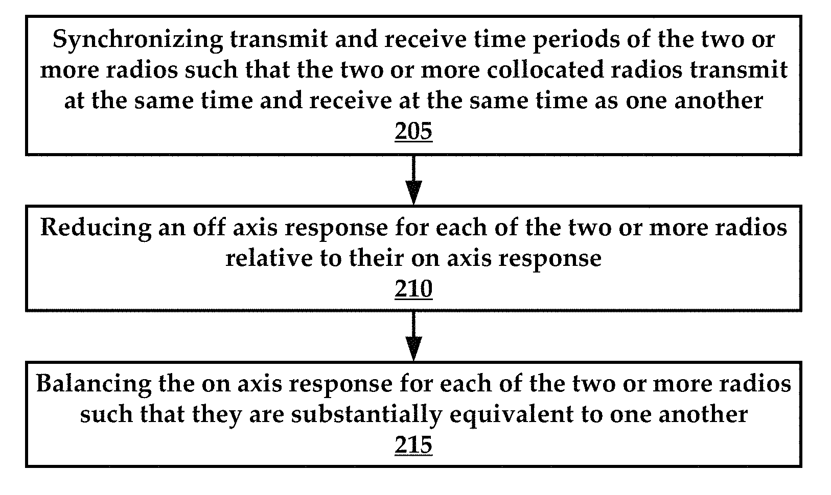
According to some embodiments, the present technology is directed to a method, comprising: (a) transmitting signals on a same channel by two or more collocated radios by: (i) synchronizing transmit and receive time periods of the two or more radios such that the two or more collocated radios transmit at the same time and receive at the same time as one another; (ii) reducing an off-axis response for each of the two or more radios relative to their on-axis response; and (iii) balancing the on-axis response for each of the two or more radios such that they are substantially equivalent to one another.
According to some embodiments, the present technology is directed to a method of communication synchronization between two or more radios, the two or more radios having angular separation or physical characteristics that optimize their on-axis responses, the method comprising: (a) selecting a shared channel for the two or more radios; (b) synchronizing transmit and receive time periods of the two or more radios such that the two or more collocated radios transmit at the same time and receive at the same time as one another on the shared channel; and (c) balancing an on-axis response for each of the two or more radios such that they are substantially equivalent to one another.
BRIEF DESCRIPTION OF THE DRAWINGS
Certain embodiments of the present technology are illustrated by the accompanying figures. It will be understood that the figures are not necessarily to scale and that details not necessary for an understanding of the technology or that render other details difficult to perceive may be omitted. It will be understood that the technology is not necessarily limited to the particular embodiments illustrated herein.
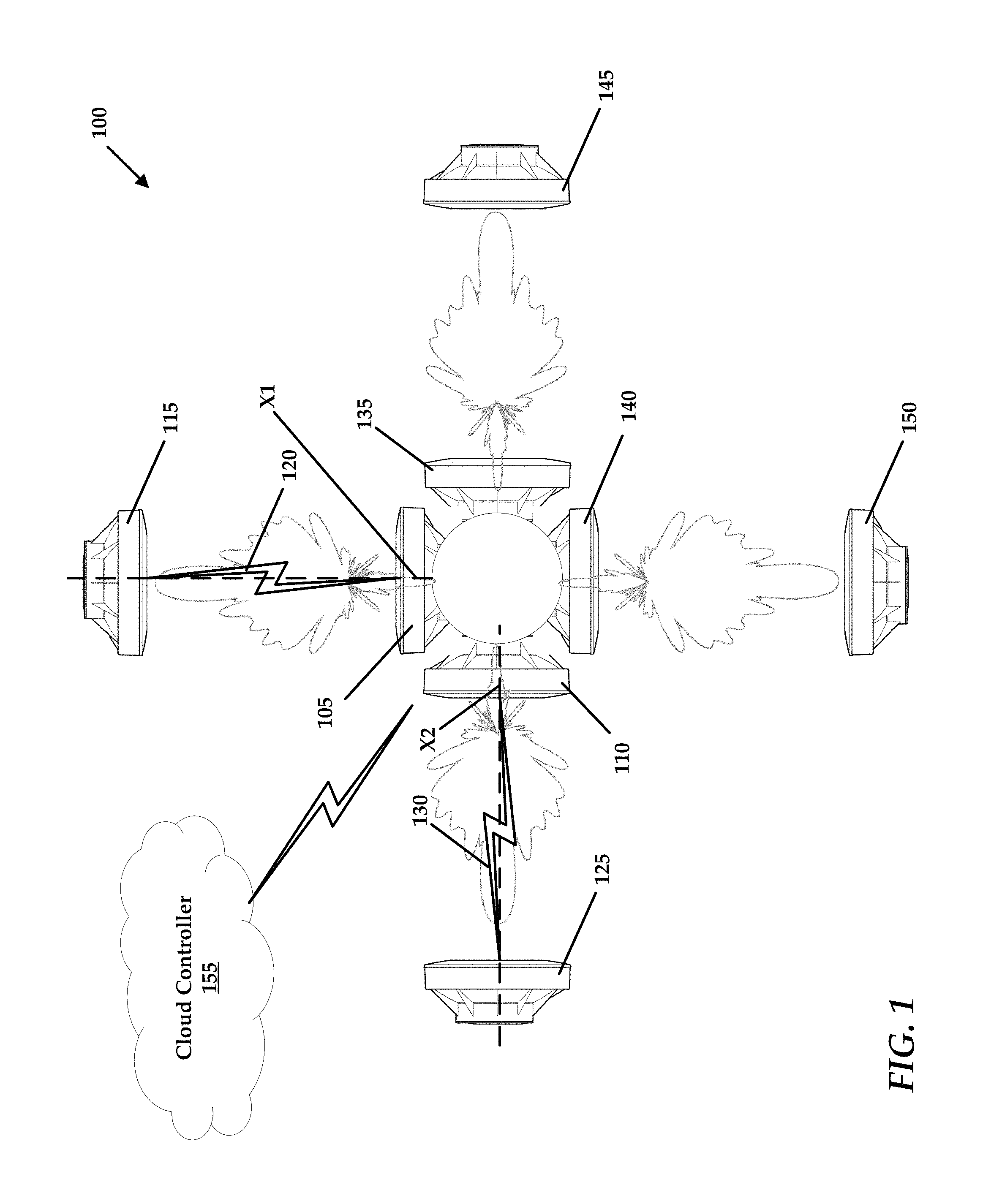
FIG. 1 is a schematic diagram of an example radio system that comprises a plurality of collocated radios that are configured to use a shared channel for communication with a plurality of far radios.
FIG. 2 is a flowchart of an example method for synchronous radio transmission on a shared channel.
FIGS. 3A-C collectively illustrate an example radio for use in accordance with the present technology.
FIG. 4 is another example method for synchronous radio transmission on a shared channel.
FIG. 5 illustrates an exemplary computing device that may be used to implement embodiments according to the present technology.
DESCRIPTION OF EXEMPLARY EMBODIMENTS
While this technology is susceptible of embodiment in many different forms, there is shown in the drawings and will herein be described in detail several specific embodiments with the understanding that the present disclosure is to be considered as an exemplification of the principles of the technology and is not intended to limit the technology to the embodiments illustrated.
It will be understood that like or analogous elements and/or components, referred to herein, may be identified throughout the drawings with like reference characters. It will be further understood that several of the figures are merely schematic representations of the present technology. As such, some of the components may have been distorted from their actual scale for pictorial clarity.
Generally speaking, the present technology provides methods for simultaneous transmission of data on a shared channel using a plurality of collocated radios.
Referring now to FIG. 1, an example radio system 100 is illustrated. The radio system 100 comprises two or more collocated radios such as radio 105 and radio 110. These radios are located in proximity to one another such that without the use of the present technology, the radios would interfere with one another when transmitting or receiving.
The radios 105 and 110 are each coupled with far radios over long range wireless links. For example, radio 105 is couplable with a first far radio 115 over a long range wireless link 120 and radio 110 is couplable with a second far radio 125 over a long range wireless link 130. To be sure, additional collocated and far radios can be utilized to practice the present technology, such as radios 135 and 140 and far radios 145 and 150.
The radio system 100 can comprise a cloud controller 155 that is utilized to control various aspects of the radio system 100 such as channel synchronization and antenna gain adjustment, as will be described in greater detail infra.
Each of the radios 105 and 110 will have an on-axis response and an off-axis response when transmitting and receiving signals. The on-axis response for a radio occurs along a main axis of a radio such as axis X1 for radio 105 and axis X2 for radio 110. For example, radio 105 will have an on-axis response to signals from the first far radio 115. An off-axis response is where interference is experienced by a radio due to overlapping signals from other radios. For example, radio 105 may have an off-axis response due to bleed over from radio 110 or over from the second far radio 125. For example, if the second far radio 125 antenna gain is too powerful its radiation pattern can partially envelop the radio 105, interfering with the on-axis signal.
Generally, the present technology utilizes a set of features that allow the radios 105 and 110 to transmit or receive in synchronization with one another. In one embodiment, the radios 105 and 110 utilize the same channel or frequency. Additionally, a signal-to-noise (SNR) ratio is maintained between the on-axis response and the off-axis response to ensure that the SNR of the radios 105 and 110 are transmitting and/or receiving a high quality signal.
Additionally, the present technology utilizes selective adjustment of the on-axis responses of the radios 105 and 110 to ensure that the on-axis responses are substantially equal to one another.
These features, when combined and optimized allow for the radios 105 and 110 to transmit in synchronization with one another, both in time and on the same channel.
With respect to optimizing an on-axis versus an off-axis response for the radios 105 and 110, the radio 105 can be placed in alignment with a reference line that extends along axis X1. The radio 110 can be placed in alignment with a reference line that extends along axis X2. To be sure, the reference line R1 and R2 are angularly spaced apart from one another by approximately 90 degrees. The angular spacing of the radios 105 and 110 function to reduce the likelihood that radiation bleed over will occur between the radios 105 and 110.
In one embodiment, each of the radios 105 and 110 comprises an enclosure that possesses side lobe rejection shrouds or foam insulation that reduces the broadcast of off-axis radiation. An example radio with enclosure is illustrated and described relative to FIGS. 3A-C.
In addition to the radios being configured to transmit data on the same channel (e.g., frequency) as one another, the radios 105 and 110 may transmit different data from one another, which increases the volume and diversity of data that can be transmitted at the same time.
It will be understood that collocated radios may be grouped together according to a common time reference, such as a time slot. That is, collocated radios may be configured to transmit simultaneously according to a schedule.
The spacing of the radios 105 and 110, as well as careful timing of the data transmissions allow for simultaneous transmission of different data using the same channel. It will be understood that using radios 105 and 110 having adequate side lobe radiation rejection may enhance the efficacy of data transmissions of the radio system 100.
According to some embodiments, the radio system 100 may implement signal synchronization using, for example, GPS time references. The radio system 100 may obtain GPS time references from a GPS satellite system (not shown). A GPS receiver may be associated with each transmitter and receiver individually and may be utilized to obtain GPS time references from the GPS satellite system. In contrast to systems that utilize a common GPS receiver to provide GPS information to a plurality of devices, integrating the GPS receiver within a device itself advantageously eliminates time deltas present in systems that require the transmission of GPS information from a GPS receiver to a desired device. That is, wired or wireless transmission of GPS information between a main GPS receiver and a plurality of devices introduces timing delays.
Thus, in some embodiments each radio 105 and 110 is provided with a GPS module that receives GPS information such as time and location data. The GPS information can be utilized to synchronize the radios 105 and 110 in their broadcast times.
The radios 105 and 110 can be selectively controlled to broadcast on a selected channel by, for example, a human installer or technician. In another example, the radios 105 and 110 are selectively controlled by the cloud controller 155 over a network.
In another embodiment, radio 105 is provided with a GPS module. Radio 105 shares its GPS information with radio 110 over a wired connection such as an Ethernet connection.
In yet another embodiment, the radios 105 and 110 are channel and time synchronized with one another over a network connection. For example, the radios 105 and 110 can receive channel and/or time parameters over a network connection from local WiFi network.
With respect to balancing the on-axis response for the radios 105 and 110, it will be understood that disparities between on-axis responses can occur in certain scenarios. For example, when radio 105 and first far radio 115 are closer one another than radio 110 and second far radio 125, and the radios are all broadcasting at approximately the same power level, the difference in proximity can cause the radio 105 to have an on-axis response that is greater than the on-axis response of the radio 110. This is due to signal power reduction due to free space loss that is greater for radio 110 than radio 105.
To deal with interference this scenario, several methods for receive signal strength balancing (i.e., equalizing) or power back-off may be implemented. One method may be to observe the distance between the radios (collocated and far) and calculating the free space path loss, thereby allowing the transmitters to approximate the power required to achieve a receive signal level. However, this is merely an approximation as path loss is mostly related to distance, but pointing errors and obstructions may add to the loss. For example, if one distance is one kilometer long and another distance is two kilometers long, based on the free space path loss, a transmission for the two kilometer distance may be 6 dBm quieter than a transmission for the one kilometer distance. To achieve the same power level in transmissions, the transmitter or radio for the one kilometer distance may be backed down by 6 dBm.
Another method of implementing power back-off may be a closed-loop method. This method may have the receiver radio communicate the current signal strength to the transmitter radio. Depending on whether the signal strength is higher or lower than the target, the transmitter radio then knows how many decibels to reduce or increase its power level to achieve the target receive signal strength.
In sum, the radios 105 and 110 can have their transmit and/or receive antenna gains selectively adjusted to compensate for disparate signal strengths in their on-axis responses. Selective adjustment of transmit or receive antenna gain can be accomplished using a microprocessor that executes gain adjustment logic stored in memory, in accordance with the examples provided above.
Advantageously, the present technology can be utilized to synchronize collocated radios owned by different entities, such as ISPs. To be sure, multiple radios operated by a plurality of entities can be collocated on public or private structures such as buildings or towers. Since these entities typically do not strategically plan their broadcast schedules, interference frequently occurs between these radios.
In some embodiments, the cloud controller 155 is configured to monitor interference between collocated radios by determining radios that are not operating in synchronization with one another. This lack of synchronization can itself be indicative of interference. In one example, a spectral scanner may be utilized at the collocated radio location to sense asynchronous broadcast periods. In other embodiments, the entities can provide the cloud controller 155 with access to broadcast schedules for their radios.
The cloud controller 155 can identify these out of synch radios and inform the owners of these radios that synchronization may improve network performance. The cloud controller 155 can then synchronize the collocated radios in their channel usage and their operational timing using the aforementioned features.
As mentioned above, the radio system 100 comprises additional collocated radios 135 and 140. The radio system 100 allows for a synchronized timing scheme may result in each transceiver may be assigned a timing. For example, radios 105 and 110 may be assigned a timing A and radios 135 and 140 may be assigned a timing B. The units with timing A transmit at the same time, while timing B units receive during this time. When timing B units are transmitting, timing A units are receiving.
Under the 802.11 standard, there are access points that typically broadcast an SSID, and there are clients/stations that associate with the access points. Using the synchronized timing scheme described above, access points may be allowed to be either timing A, or timing B units, and similarly allow clients/stations to be either. This is necessary, because all radios per tower or site must have the same timing gender to avoid interference, and yet not all radios per location are necessarily access points or clients/stations exclusively.
After placement or installation of the various radios of the radio system 100, each radio may be configured to execute a configuration cycle in order to communicatively couple itself with the radio system 100. The configuration cycle may include execution of a site survey, where the device determines whether a radio is a transmitter or receiver. Because the radios used herein may operate as a transmitter or a receiver, the radio may initially determine whether it has been purposed as a transmitter or a receiver. The radio may be pre-loaded (executable instructions stored in memory) with an augmented service identifier (SSID) information set. Rather than just including a typical identifier that is used to uniquely identify a device on a network, the augmented SSID information set of the present technology may additionally include location information (e.g., latitude and longitude) as well as a mode of operation and security type (e.g., security protocol used by the radio). The location information may allow the radio to deduce or determine additional radios with which the radio has been collocated. If the radio is replacing another radio, a mode of operation instruction set may be provided to the replacement radio that informs the radio of its required mode of operation.
The mode of operation may inform the radio of its broadcast and/or receiving schedules, as well as channel information, such as the shared channel utilized by the plurality of radios.
According to some embodiments, the radio may, upon power up, enter into scan mode to determine a list of collocated radios, as well as broadcast its own SSID to other collocated radios. The radio may then exit the scan mode and perform a manual rescan, listing for configuration information. The radio may reset configuration details to default or factory settings. In other instances, the configuration details determined by the radio during the scan session may be installed or accepted by the radio.
In some instances, if a radio needs to determine its location information, the radio may be configured to broadcast ping signals that are received by, for example, receivers/radios that are not collocated with the radio. Using the time differential between transmission of a ping signal by a radio, relative to receiving of the ping signal by a receiver, an approximate distance between radios may be determined. Again, a GPS counter may track the broadcast and receipt of signals. The radio system may compare the GPS time references associated with the broadcast and received signals to determine distance values.
In other embodiments, each radio (transmitter or receiver) may utilize a media access control (MAC) layer protocol that uses GPS coordinates. When a site survey is conducted, the latitude and longitude of each transmitter and receiver is shown on a map, which may be displayed via a graphical user interface. In other instances, the site survey data points may be stored in a log file.
Additional features can also be implemented, above and beyond radio synchronization. For example, the radio system 100 of FIG. 1 can be configured to selectively vary transmit and receive bandwidth.
In one embodiment, the radio system 100 of FIG. 1, in operation may provide in the 80 megahertz spectrum, 802.11ac wireless data transmission having TCP/IP bandwidth of approximately 4.8 gigabits per second (Gbps), which includes 2.4 Gbps of upload bandwidth and 2.4 Gbps of download bandwidth, assuming the transmit/receive workload of the radio system 100 is split evenly at 50 percent transmit and 50 percent receive. For each antenna the TCP/IP bandwidth may be approximately 1 Gbps to 1.2 Gbps, which includes 500 megabits per second (Mbps) to 600 Mbps of upload bandwidth and 500 Mbps to 600 Mbps of download bandwidth, assuming the transmit/receive workload of the antenna split evenly between 50 percent transmit and 50 percent receive. Advantageously, the available bandwidth of the radio system 100 may be selectively adjusted such that more bandwidth may be dedicated to download bandwidth. For example, the bandwidth split may be selectively adjusted such that the download bandwidth is 70 percent of the total bandwidth of the radio system 100 while the upload bandwidth is approximately 30 percent. Such selective adjustment allows for fine tuning of the radio system 100 to service the needs of end users. For example, when end users frequently consume more download bandwidth than upload bandwidth, the download bandwidth may be increased. This bandwidth split may be automatically varied according to the empirical end user behavior. While the embodiment described provides for wireless data transmission in the 80 MHz spectrum, other embodiments may utilize up to the 160 MHz spectrum, inclusive of the 20 MHz, 40 MHz, or 80 MHz spectrums beneath it.
FIG. 2 is a flowchart of an example method that is executed in accordance with the present technology. In some embodiments, the method includes transmitting signals on a same channel by two or more collocated radios by initially synchronizing 205 transmit and receive time periods of the two or more radios such that the two or more collocated radios transmit at the same time and receive at the same time as one another.
Again, the radios are collocated in proximity to one another such that without use of the present technology, the radios would interfere with one another when broadcasting and/or receiving.
The method also includes reducing 210 an off-axis response for each of the two or more radios relative to their on-axis response. For example, the reduction in off-axis response can occur with the use of side lobe rejecting enclosures or with adequate angular separation between radios.
Additionally, the method includes balancing 215 the on-axis response for each of the two or more radios such that they are substantially equivalent to one another.
To be sure, the steps of the method need be executed in any particular order. Thus, the reduction in off-axis response may occur due to physical properties or placement of radios, which can occur prior to channel and time synchronization, as well as on-axis response balancing.
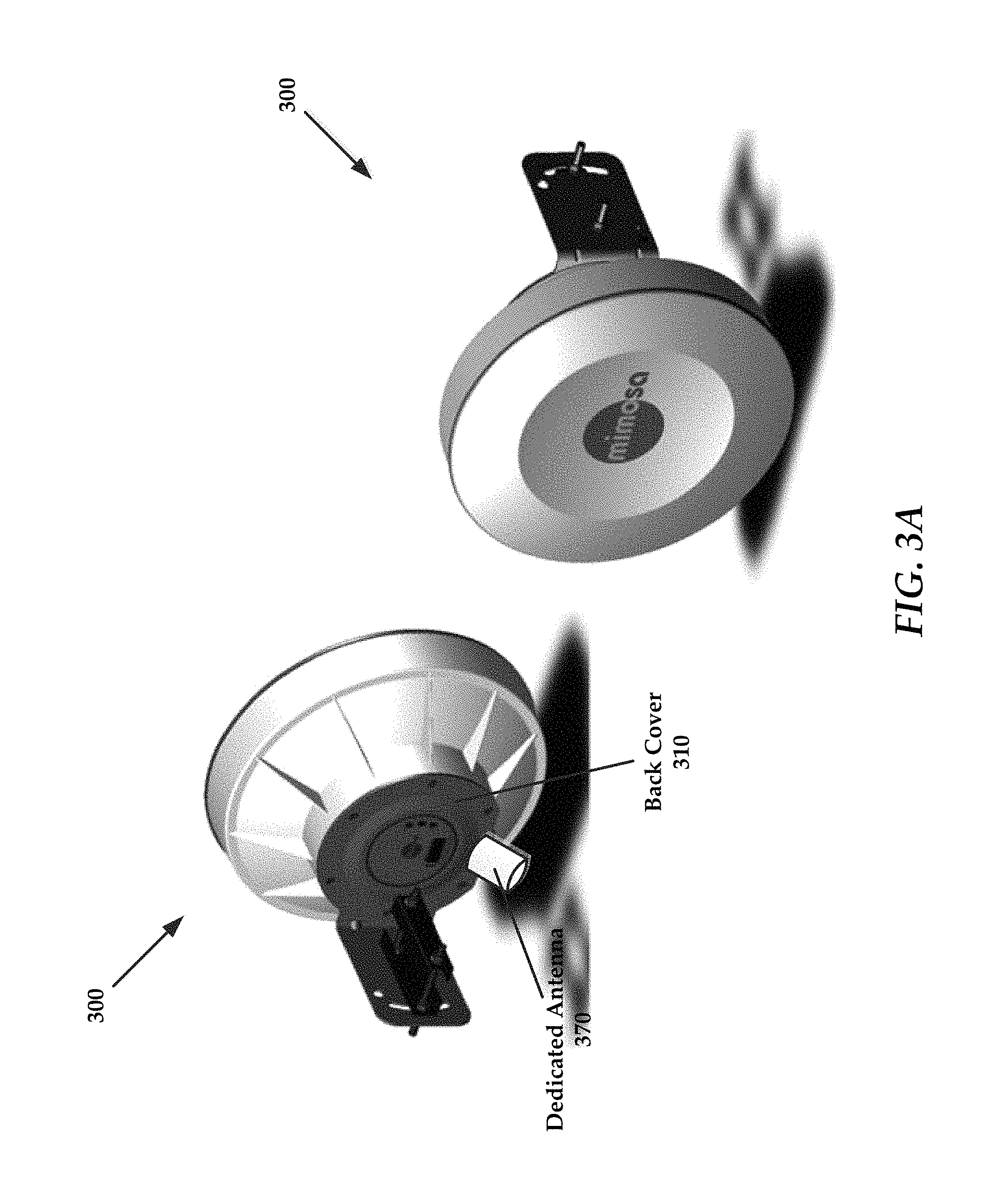
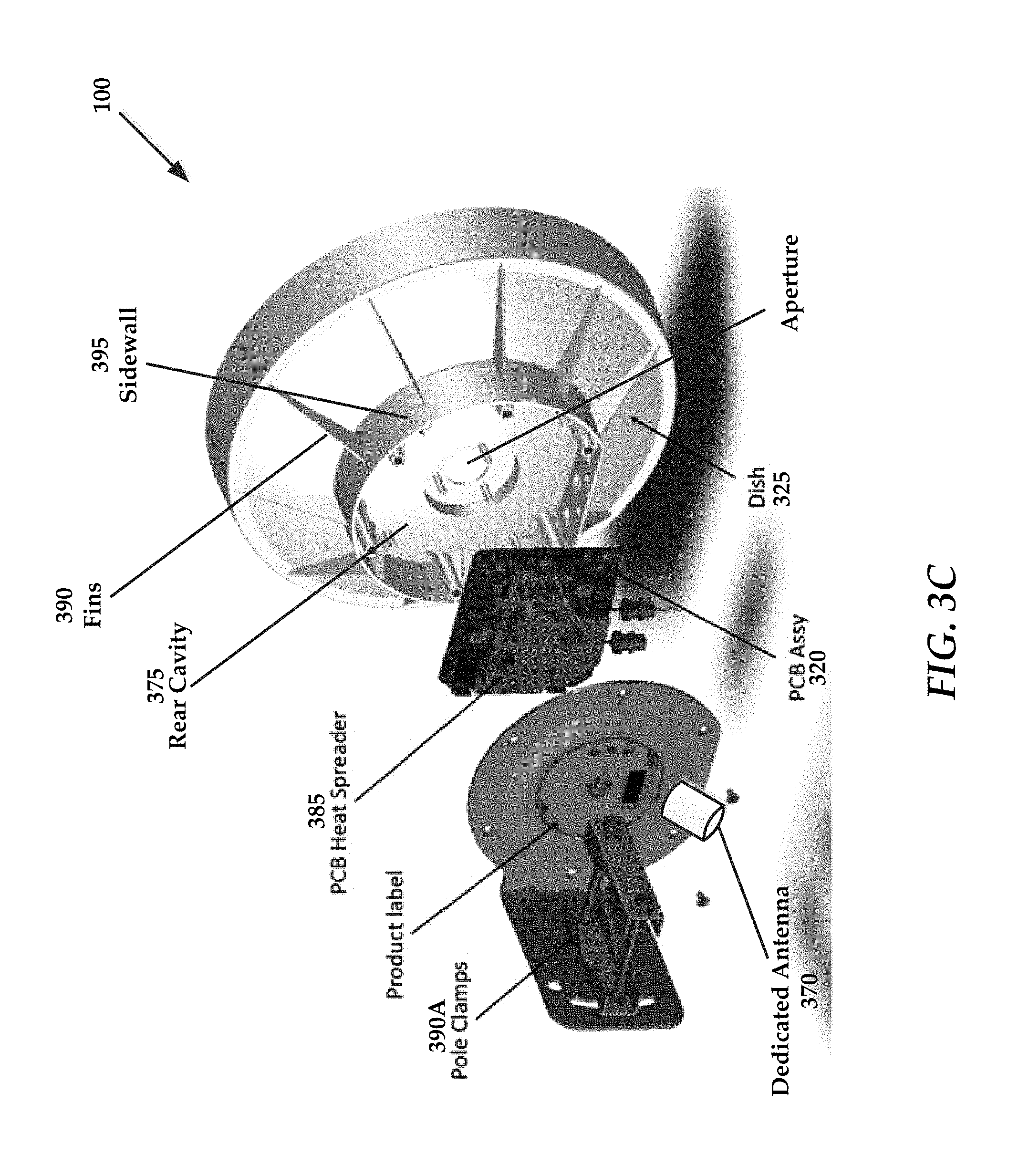
FIGS. 3A-C collectively illustrate an exemplary device 300. FIG. 3A includes front and rear perspective views of a device 300 in an assembled configuration. The device 300 is provided with a dedicated antenna 370 that extends from a back cover 310 of the device 300.
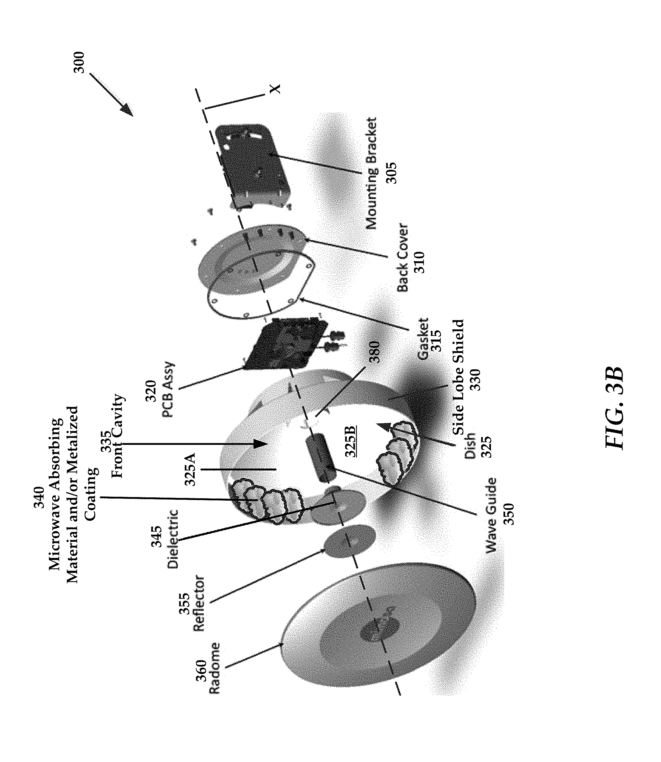
FIG. 3B is an exploded perspective view of the device 300 (e.g., radio). Generally, the device 300 comprises a mounting bracket 305, a back cover 310, a gasket 315, a PCB (printed circuit board) assembly 320, a dish 325, a cylindrical dielectric plate 345, a reflector 355, and a radome 360.
It will be understood that advantageously, the dish of the present technology is manufactured monolithically as one piece. That is, the dish antenna (also referred to as "dish") 325 includes a parabolic circular reflector 325B that is bounded by the side lobe shield 330 to form the front cavity 335, and rear cavity 375. All these components are manufactured as a single device, as opposed to technologies where dishes are formed from separate components that are assembled in the field. Further, many dishes are an amalgamation of parts from a plurality of manufacturers, which can lead to physical incompatibility and on the fly modification in the field.
Advantageously, the monolithic dish provides advantages such as reduced manufacturing cost, since the dish can be manufactured in a single process. For example, the dish can be manufactured using injection molding, or any other similar process that is capable of producing a dish with the physical features as those illustrated in the drawings of the disclosure.
Another advantage of the monolithic structure is that it allows for storage and incorporation of necessary electronics for the antenna within the dish. For example, the PCB assembly 320 can be housed within the rear cavity 375. This places the PCB assembly 320 and waveguide 350 (discussed in greater detail below) in very close proximity to the parabolic circular reflector 325B, which reduces or eliminates signal attenuation of signals produced by the PCB assembly 320 that are directed through the waveguide 350 that would be present if the PCB assembly 320 and/or waveguide 350 are not located proximate the parabolic circular reflector 325B.
The mounting bracket 305 that allows the device 300 to be pivotally coupled to a mounting surface, such as a tower (not shown). The ability of the device 300 to be pivotally connected to a mounting surface allows for an azimuth angle to be established, as would be known to one of ordinary skill in the art with the present disclosure before them. While the mounting bracket 305 has been described, the device 300 couples with a structure using any one or more of a number of mechanisms that would be apparent to one of ordinary skill in the art with the present disclosure before them. The mounting bracket 305 couples with a back cover via a plurality of fasteners. The mounting bracket 305 couples to the back cover 310 using fasteners.
In some embodiments, the mounting bracket 305 couples with a set of pole clamps 390A that allow the device 300 to be clamped to a pole or other similar structure.
The device 300 also comprises a dish antenna 325 that is formed so as to include a rear cavity 375 (see FIG. 3C) and a front cavity 335. A PCB assembly 320 is disposed at least partially within the rear cavity of the dish. The PCB assembly 320 includes any circuits needed to operate the device 300. In some embodiments, the dish antenna 325 is a parabolic circular reflector 325B that is bounded by the side lobe shield 330 to form the front cavity 335. The front cavity extends forwardly from the dish.
The shape of the parabolic reflector 325B depends upon the desired radiation pattern for the device 300. Thus, the exact shape and size of the parabolic circular reflector 325B varies according to design and implementational requirements.
A seal, such as a gasket 315, is disposed between the outer peripheral edge of the rear cavity 375 and the back cover 310 to sealingly protect the PCB assembly 320 from contamination. The PCB assembly 320 also includes a PCB heat spreader 385 or other means for transferring heat generated by the PCB assembly 320 to the ambient environment such as fans and so forth.
In some instances, the dish 325 includes a side lobe shield 330 that extends beyond the outer peripheral edge of the dish 325. In some instances the side lobe shield 330 is a shroud having a sidewall that forms a ring around the outer peripheral edge of an upper surface of the dish 325. The side lobe shield 330 extends from the dish 325 axially along a longitudinal axis X of the device 300.
The dish 325, in some embodiments, is manufactured as a monolithic or one piece device. The dish 325 is manufactured from any one or combination of materials that are suitable for use as with an antenna.
Advantageously, the inner surface of the side lobe shield 330 is provided with a metalized coating. The upper surface 325A of the parabolic circular reflector 325B also includes a metalized coating. In some instances at least a portion of the inner surface of the side lobe shield is augmented with a metallic coating and/or a microwave absorbing material (also referred to as "material") 340, such as a foam or other electrically insulating material that is coated along the inner surface of the front cavity 335 of the dish 325. For example, the material 340 lines the inner portion of the side lobe shield 330.
The upper surface 325A is generally circular and parabolic in shape, which aids in directing radiation along the longitudinal axis X. Again, the shape of the dish 325 functions to reduce emissions of side lobe radiation. In some embodiments, the dish 325 has an annular shaped mounting ring 380 that is configured to receive the wave guide 350.
The microwave absorbing material 340 is shown as being disposed within the front cavity 335 in FIG. 3B, but can also be applied or sprayed to the inner surface of the side lobe shield 330. In other instances, the microwave absorbing material 340 is integrated into the side lobe shield 330 itself. That is, the side lobe shield 330 is manufactured as a layered or composite. For example, the side lobe shield 330 comprises a substrate of a metallic material that has a layer of microwave absorbing material applied thereto. Specifically, the absorbing material would be applied to a surface of the side lobe shield that is proximate the wave guide 350 of the device.
In other embodiments, a metalized coating is applied to the entire upper surface of the dish 325 and the inner sidewall of the side lobe shield 330.
Because the side lobe shield 330 extends beyond the outer peripheral edge of the dish 325, the side lobe shield 330 functions to direct the signals reflected by the dish surface in a more uniform and directed pattern. For example, the side lobe shield 330 reduces side lobe radiation which is transmitted from and/or received by the device 300. Thus, the device 300 reduces an amount of signals (e.g., radiation) which are received by the device 300 such as those transmitted by adjacent transmitters. Also, the side lobe shield 330 of the device 300 also reduces an amount of microwave signals transmitted via side lobe projection by the device 300. Thus, the device 300 reduces both the transmission and reception of deleterious side lobe signals.
The device 300 also comprises a wave guide 350 that is communicatively coupled with the PCB assembly 320. A cylindrical dielectric plate 345 couples with the wave guide 350. Also, a reflector 355 is associated with the cylindrical dielectric plate 345. The combination of the PCB assembly 320, wave guide 350, cylindrical dielectric plate 345, and reflector 355 are collectively referred to as a "radio." A radome cover 360 attaches to the side lobe shield 330 to sealingly cover the reflector 355, cylindrical dielectric plate 345, and wave guide 350 that are housed within the front cavity 335.
It will be understood that the radome 360, side lobe shield 330, dish 325, and back cover 310 of the device 300 is constructed from any suitable material such as a plastic, a polymeric material, a resin, a composite material, a natural material, or any other material that would be known to one of ordinary skill in the art.
According to some embodiments, the dish 325 and the side lobe shield 330 is manufactured as an integral unit. Moreover, the rear cavity 375 of the dish 325 is formed to provide a mounting surface for receiving the PCB assembly 320. The rear cavity 375 is formed by a sidewall 395 that extends rearwardly from the dish antenna 325 along the longitudinal axis X. The sidewall 395 extends in an opposing direction from the side lobe shield 330.
The dish 325, as an integral unit, is manufactured from a plastic material, a polymeric material, a resin, a composite material, or other suitable material that would be known to one of ordinary skill in the art with the present disclosure before them. As mentioned before, the inner sidewall of the side lobe shield 330 and the upper surface 325A of the dish 325 is metalized while the rear cavity 375 is not metalized. Additionally, the side lobe shield 330 is provided with a microwave insulating material.
According to some embodiments, the dish antenna 325 comprises a series of fins 390. These fins 390 may extend from the rear cavity 375 upwardly to the edge of the side lobe shield 330. More specifically, the series of fins extends upwardly from the sidewall of the rear cavity along an underside of the parabolic circular reflector or dish 325.
FIG. 4 is a flowchart of another example method of the present technology. To be sure, the method involves communication synchronization between two or more radios. As mentioned herein, the two or more radios have angular separation or physical characteristics that optimize their on-axis responses.
The method can include an optional step of detecting 405 interference between the radios. This could include a cloud controller that is configured to detect when collocated radios are interfering with one another by detecting non-synchronized broadcast time periods of multiple radios. The method can also omit step 405 in some embodiments.
In one embodiment, the method includes selecting 410 a shared channel for the two or more radios. For example, the cloud controller can select 80 MHz as the shared frequency/channel.
Next, the method includes synchronizing 415 transmit and receive time periods of the two or more radios such that the two or more collocated radios transmit at the same time and receive at the same time as one another on the shared channel. As mentioned above, this could be accomplished using GPS modules in each of the radios.
In some embodiments, the method includes balancing 420 an on-axis response for each of the two or more radios such that they are substantially equivalent to one another.
Indeed, the combination of on-axis response balancing with off-axis response reduction to produce adequate signal to noise ratio at each of the radios, as well as time and channel uniformity allow for synchronized transmission of data by two or more collocated radios.
FIG. 5 is a diagrammatic representation of an example machine in the form of a computer system 1, within which a set of instructions for causing the machine to perform any one or more of the methodologies discussed herein may be executed. In various example embodiments, the machine operates as a standalone device or may be connected (e.g., networked) to other machines. In a networked deployment, the machine may operate in the capacity of a server or a client machine in a server-client network environment, or as a peer machine in a peer-to-peer (or distributed) network environment. The machine may be a radio, a base station, a personal computer (PC), a web appliance, a network router, switch or bridge, or any machine capable of executing a set of instructions (sequential or otherwise) that specify actions to be taken by that machine. Further, while only a single machine is illustrated, the term "machine" shall also be taken to include any collection of machines that individually or jointly execute a set (or multiple sets) of instructions to perform any one or more of the methodologies discussed herein.
The example computer system 1 includes a processor or multiple processors 5 (e.g., a central processing unit (CPU), a graphics processing unit (GPU), or both), and a main memory 10 and static memory 15, which communicate with each other via a bus 20. The computer system 1 may further include a video display 35 (e.g., a liquid crystal display (LCD)). The computer system 1 may also include an alpha-numeric input device(s) 30 (e.g., a keyboard), a cursor control device (e.g., a mouse), a voice recognition or biometric verification unit (not shown), a drive unit 37 (also referred to as disk drive unit), a signal generation device 40 (e.g., a speaker), and a network interface device 45. The computer system 1 may further include a data encryption module (not shown) to encrypt data.
The disk drive unit 37 includes a computer or machine-readable medium 50 on which is stored one or more sets of instructions and data structures (e.g., instructions 55) embodying or utilizing any one or more of the methodologies or functions described herein. The instructions 55 may also reside, completely or at least partially, within the main memory 10 and/or within the processors 5 during execution thereof by the computer system 1. The main memory 10 and the processors 5 may also constitute machine-readable media.
The instructions 55 may further be transmitted or received over a network via the network interface device 45 utilizing any one of a number of well-known transfer protocols (e.g., Hyper Text Transfer Protocol (HTTP)). While the machine-readable medium 50 is shown in an example embodiment to be a single medium, the term "computer-readable medium" should be taken to include a single medium or multiple media (e.g., a centralized or distributed database and/or associated caches and servers) that store the one or more sets of instructions. The term "computer-readable medium" shall also be taken to include any medium that is capable of storing, encoding, or carrying a set of instructions for execution by the machine and that causes the machine to perform any one or more of the methodologies of the present application, or that is capable of storing, encoding, or carrying data structures utilized by or associated with such a set of instructions. The term "computer-readable medium" shall accordingly be taken to include, but not be limited to, solid-state memories, optical and magnetic media, and carrier wave signals. Such media may also include, without limitation, hard disks, floppy disks, flash memory cards, digital video disks, random access memory (RAM), read only memory (ROM), and the like. The example embodiments described herein may be implemented in an operating environment comprising software installed on a computer, in hardware, or in a combination of software and hardware.
Not all components of the computer system 1 are required and thus portions of the computer system 1 can be removed if not needed, such as I/O devices.
One skilled in the art will recognize that the Internet service may be configured to provide Internet access to one or more computing devices that are coupled to the Internet service, and that the computing devices may include one or more processors, buses, memory devices, display devices, input/output devices, and the like. Furthermore, those skilled in the art may appreciate that the Internet service may be coupled to one or more databases, repositories, servers, and the like, which may be utilized in order to implement any of the embodiments of the disclosure as described herein.
The corresponding structures, materials, acts, and equivalents of all means or step plus function elements in the claims below are intended to include any structure, material, or act for performing the function in combination with other claimed elements as specifically claimed. The description of the present technology has been presented for purposes of illustration and description, but is not intended to be exhaustive or limited to the present technology in the form disclosed. Many modifications and variations will be apparent to those of ordinary skill in the art without departing from the scope and spirit of the present technology. Exemplary embodiments were chosen and described in order to best explain the principles of the present technology and its practical application, and to enable others of ordinary skill in the art to understand the present technology for various embodiments with various modifications as are suited to the particular use contemplated.
Aspects of the present technology are described above with reference to flowchart illustrations and/or block diagrams of methods, apparatus (systems) and computer program products according to embodiments of the present technology. It will be understood that each block of the flowchart illustrations and/or block diagrams, and combinations of blocks in the flowchart illustrations and/or block diagrams, can be implemented by computer program instructions. These computer program instructions may be provided to a processor of a general purpose computer, special purpose computer, or other programmable data processing apparatus to produce a machine, such that the instructions, which execute via the processor of the computer or other programmable data processing apparatus, create means for implementing the functions/acts specified in the flowchart and/or block diagram block or blocks.
These computer program instructions may also be stored in a computer readable medium that can direct a computer, other programmable data processing apparatus, or other devices to function in a particular manner, such that the instructions stored in the computer readable medium produce an article of manufacture including instructions which implement the function/act specified in the flowchart and/or block diagram block or blocks.
The computer program instructions may also be loaded onto a computer, other programmable data processing apparatus, or other devices to cause a series of operational steps to be performed on the computer, other programmable apparatus or other devices to produce a computer implemented process such that the instructions which execute on the computer or other programmable apparatus provide processes for implementing the functions/acts specified in the flowchart and/or block diagram block or blocks.
The flowchart and block diagrams in the Figures illustrate the architecture, functionality, and operation of possible implementations of systems, methods and computer program products according to various embodiments of the present technology. In this regard, each block in the flowchart or block diagrams may represent a module, segment, or portion of code, which comprises one or more executable instructions for implementing the specified logical function(s). It should also be noted that, in some alternative implementations, the functions noted in the block may occur out of the order noted in the figures. For example, two blocks shown in succession may, in fact, be executed substantially concurrently, or the blocks may sometimes be executed in the reverse order, depending upon the functionality involved. It will also be noted that each block of the block diagrams and/or flowchart illustration, and combinations of blocks in the block diagrams and/or flowchart illustration, can be implemented by special purpose hardware-based systems that perform the specified functions or acts, or combinations of special purpose hardware and computer instructions.
In the following description, for purposes of explanation and not limitation, specific details are set forth, such as particular embodiments, procedures, techniques, etc. in order to provide a thorough understanding of the present invention. However, it will be apparent to one skilled in the art that the present invention may be practiced in other embodiments that depart from these specific details.
Reference throughout this specification to "one embodiment" or "an embodiment" means that a particular feature, structure, or characteristic described in connection with the embodiment is included in at least one embodiment of the present invention. Thus, the appearances of the phrases "in one embodiment" or "in an embodiment" or "according to one embodiment" (or other phrases having similar import) at various places throughout this specification are not necessarily all referring to the same embodiment. Furthermore, the particular features, structures, or characteristics may be combined in any suitable manner in one or more embodiments. Furthermore, depending on the context of discussion herein, a singular term may include its plural forms and a plural term may include its singular form. Similarly, a hyphenated term (e.g., "on-demand") may be occasionally interchangeably used with its non-hyphenated version (e.g., "on demand"), a capitalized entry (e.g., "Software") may be interchangeably used with its non-capitalized version (e.g., "software"), a plural term may be indicated with or without an apostrophe (e.g., PE's or PEs), and an italicized term (e.g., "N+1") may be interchangeably used with its non-italicized version (e.g., "N+1"). Such occasional interchangeable uses shall not be considered inconsistent with each other.
Also, some embodiments may be described in terms of "means for" performing a task or set of tasks. It will be understood that a "means for" may be expressed herein in terms of a structure, such as a processor, a memory, an I/O device such as a camera, or combinations thereof. Alternatively, the "means for" may include an algorithm that is descriptive of a function or method step, while in yet other embodiments the "means for" is expressed in terms of a mathematical formula, prose, or as a flow chart or signal diagram.
The terminology used herein is for the purpose of describing particular embodiments only and is not intended to be limiting of the invention. As used herein, the singular forms "a", "an" and "the" are intended to include the plural forms as well, unless the context clearly indicates otherwise. It will be further understood that the terms "comprises" and/or "comprising," when used in this specification, specify the presence of stated features, integers, steps, operations, elements, and/or components, but do not preclude the presence or addition of one or more other features, integers, steps, operations, elements, components, and/or groups thereof.
It is noted at the outset that the terms "coupled," "connected", "connecting," "electrically connected," etc., are used interchangeably herein to generally refer to the condition of being electrically/electronically connected. Similarly, a first entity is considered to be in "communication" with a second entity (or entities) when the first entity electrically sends and/or receives (whether through wireline or wireless means) information signals (whether containing data information or non-data/control information) to the second entity regardless of the type (analog or digital) of those signals. It is further noted that various figures (including component diagrams) shown and discussed herein are for illustrative purpose only, and are not drawn to scale.
If any disclosures are incorporated herein by reference and such incorporated disclosures conflict in part and/or in whole with the present disclosure, then to the extent of conflict, and/or broader disclosure, and/or broader definition of terms, the present disclosure controls. If such incorporated disclosures conflict in part and/or in whole with one another, then to the extent of conflict, the later-dated disclosure controls.
The terminology used herein can imply direct or indirect, full or partial, temporary or permanent, immediate or delayed, synchronous or asynchronous, action or inaction. For example, when an element is referred to as being "on," "connected" or "coupled" to another element, then the element can be directly on, connected or coupled to the other element and/or intervening elements may be present, including indirect and/or direct variants. In contrast, when an element is referred to as being "directly connected" or "directly coupled" to another element, there are no intervening elements present. The description herein is illustrative and not restrictive. Many variations of the technology will become apparent to those of skill in the art upon review of this disclosure. For example, the technology is not limited to use for stopping email threats, but applies to any messaging threats including email, social media, instant messaging, and chat.
While various embodiments have been described above, it should be understood that they have been presented by way of example only, and not limitation. The descriptions are not intended to limit the scope of the invention to the particular forms set forth herein. To the contrary, the present descriptions are intended to cover such alternatives, modifications, and equivalents as may be included within the spirit and scope of the invention as defined by the appended claims and otherwise appreciated by one of ordinary skill in the art. Thus, the breadth and scope of a preferred embodiment should not be limited by any of the above-described exemplary embodiments.
* * * * *
References
D00000
D00001
D00002
D00003
D00004
D00005
D00006
D00007
XML
uspto.report is an independent third-party trademark research tool that is not affiliated, endorsed, or sponsored by the United States Patent and Trademark Office (USPTO) or any other governmental organization. The information provided by uspto.report is based on publicly available data at the time of writing and is intended for informational purposes only.
While we strive to provide accurate and up-to-date information, we do not guarantee the accuracy, completeness, reliability, or suitability of the information displayed on this site. The use of this site is at your own risk. Any reliance you place on such information is therefore strictly at your own risk.
All official trademark data, including owner information, should be verified by visiting the official USPTO website at www.uspto.gov. This site is not intended to replace professional legal advice and should not be used as a substitute for consulting with a legal professional who is knowledgeable about trademark law.