MPO optical fiber connector
Takano , et al. Oc
U.S. patent number 10,444,442 [Application Number 15/802,693] was granted by the patent office on 2019-10-15 for mpo optical fiber connector. This patent grant is currently assigned to Senko Advanced Components, Inc.. The grantee listed for this patent is SENKO Advanced Components, Inc.. Invention is credited to Man Ming Ho, Siu Kei Ma, Kazuyoshi Takano.


View All Diagrams
| United States Patent | 10,444,442 |
| Takano , et al. | October 15, 2019 |
MPO optical fiber connector
Abstract
A multiple push-on (MPO) optical connector is provided having a ferrule configured to house multiple optical fibers and a housing having a distal end in a connection direction configured to hold the ferrule. The housing further includes a pair of proximal apertures and at least one proximal groove. A backpost has a distal end that urges the ferrule toward the distal end of the housing and a proximal end configured to receive a crimp ring. The backpost includes a pair of proximally extending latch arms that reverse latch in the proximal apertures of the housing. To strengthen the connector in side-loading environments, the backpost further includes a reinforcing rib that is received in the housing proximal groove. In a further aspect, the proximal end of the backpost may include a neck with an approximately curved side profile that, following crimping with a stepped crimp ring, results in an angled crimp.
| Inventors: | Takano; Kazuyoshi (Southborough, MA), Ho; Man Ming (Hong Kong, HK), Ma; Siu Kei (Hong Kong, HK) | ||||||||||
|---|---|---|---|---|---|---|---|---|---|---|---|
| Applicant: |
|
||||||||||
| Assignee: | Senko Advanced Components, Inc.
(Marlborough, MA) |
||||||||||
| Family ID: | 66327026 | ||||||||||
| Appl. No.: | 15/802,693 | ||||||||||
| Filed: | November 3, 2017 |
Prior Publication Data
| Document Identifier | Publication Date | |
|---|---|---|
| US 20190137700 A1 | May 9, 2019 | |
| Current U.S. Class: | 1/1 |
| Current CPC Class: | G02B 6/3887 (20130101); G02B 6/3893 (20130101); G02B 6/3857 (20130101); G02B 6/3885 (20130101); G02B 6/3821 (20130101); G02B 6/3825 (20130101); G02B 6/3831 (20130101) |
| Current International Class: | G02B 6/38 (20060101) |
References Cited [Referenced By]
U.S. Patent Documents
| 4150790 | April 1979 | Potter |
| 4327964 | May 1982 | Haesly et al. |
| 4478473 | October 1984 | Frear |
| 4762388 | August 1988 | Tanaka et al. |
| 4764129 | August 1988 | Jones et al. |
| 4840451 | June 1989 | Sampson et al. |
| 4844570 | July 1989 | Tanabe |
| 4872736 | October 1989 | Myers et al. |
| 4979792 | December 1990 | Weber et al. |
| 5041025 | August 1991 | Haitmanek |
| 5074637 | December 1991 | Rink |
| D323143 | January 1992 | Ohkura et al. |
| 5212752 | May 1993 | Stephenson et al. |
| 5265181 | November 1993 | Chang |
| 5280552 | January 1994 | Yokoi et al. |
| 5289554 | February 1994 | Cubukclyan et al. |
| 5317663 | May 1994 | Beard et al. |
| 5335301 | August 1994 | Newman et al. |
| 5348487 | September 1994 | Marazzi et al. |
| 5444806 | August 1995 | de Marchi et al. |
| 5481634 | January 1996 | Anderson et al. |
| 5506922 | April 1996 | Grois et al. |
| 5521997 | May 1996 | Rovenolt et al. |
| 5570445 | October 1996 | Chou et al. |
| 5588079 | December 1996 | Tanabe et al. |
| 5684903 | November 1997 | Kyomasu et al. |
| 5687268 | November 1997 | Stephenson et al. |
| 5781681 | July 1998 | Manning |
| 5915056 | June 1999 | Bradley et al. |
| 5937130 | August 1999 | Amberg et al. |
| 5956444 | September 1999 | Duda et al. |
| 5971626 | October 1999 | Knodell et al. |
| 6041155 | March 2000 | Anderson et al. |
| 6049040 | April 2000 | Biles et al. |
| 6134370 | October 2000 | Childers et al. |
| 6178283 | January 2001 | Weigel |
| 6186670 | February 2001 | Austin et al. |
| RE37080 | March 2001 | Stephenson et al. |
| 6206577 | March 2001 | Hall, III et al. |
| 6206581 | March 2001 | Driscoll et al. |
| 6227717 | May 2001 | Ott et al. |
| 6238104 | May 2001 | Yamakawa et al. |
| 6247849 | June 2001 | Liu |
| 6347888 | February 2002 | Puetz |
| 6461054 | October 2002 | Iwase |
| 6471412 | October 2002 | Belenkiy |
| 6478472 | November 2002 | Anderson et al. |
| 6551117 | April 2003 | Poplawski et al. |
| 6579014 | June 2003 | Melton et al. |
| 6634801 | October 2003 | Waldron et al. |
| 6648520 | November 2003 | McDonald et al. |
| 6682228 | January 2004 | Rathnam et al. |
| 6685362 | February 2004 | Burkholder et al. |
| 6695486 | February 2004 | Falkenberg |
| 6785460 | August 2004 | de Jong et al. |
| 6817780 | November 2004 | Ngo |
| 6854894 | February 2005 | Yunker et al. |
| 6872039 | March 2005 | Baus et al. |
| 6935789 | August 2005 | Gross, III et al. |
| 7020376 | March 2006 | Dang et al. |
| 7090406 | August 2006 | Melton et al. |
| 7090407 | August 2006 | Melton et al. |
| 7091421 | August 2006 | Kukita et al. |
| 7111990 | September 2006 | Melton et al. |
| 7113679 | September 2006 | Melton et al. |
| D533504 | December 2006 | Lee |
| D534124 | December 2006 | Taguchi |
| 7150567 | December 2006 | Luther et al. |
| 7153041 | December 2006 | Mine et al. |
| 7198409 | April 2007 | Smith et al. |
| 7207724 | April 2007 | Gurreri |
| D543146 | May 2007 | Chen et al. |
| 7241056 | July 2007 | Kuffel et al. |
| 7258493 | August 2007 | Milette |
| 7281859 | October 2007 | Mudd et al. |
| D558675 | January 2008 | Chien et al. |
| 7315682 | January 2008 | En Lin et al. |
| 7325976 | February 2008 | Gurreri et al. |
| 7325980 | February 2008 | Pepe |
| 7329137 | February 2008 | Martin et al. |
| 7331718 | February 2008 | Yazaki et al. |
| 7354291 | April 2008 | Caveney et al. |
| 7371082 | May 2008 | Zimmel et al. |
| D572661 | June 2008 | En Lin et al. |
| 7387447 | June 2008 | Mudd et al. |
| 7390203 | June 2008 | Murano et al. |
| 7431604 | October 2008 | Waters et al. |
| 7463803 | December 2008 | Cody et al. |
| 7465180 | December 2008 | Kusuda et al. |
| 7510335 | March 2009 | Su et al. |
| 7513695 | April 2009 | Lin et al. |
| 7561775 | July 2009 | Lin et al. |
| 7591595 | September 2009 | Lu et al. |
| 7594766 | September 2009 | Sasser et al. |
| 7641398 | January 2010 | O'Riorden et al. |
| 7654748 | February 2010 | Kuffel et al. |
| 7695199 | April 2010 | Teo et al. |
| 7699533 | April 2010 | Milette |
| 7824113 | November 2010 | Wong et al. |
| 7837395 | November 2010 | Lin et al. |
| D641708 | July 2011 | Yamauchi |
| 8186890 | May 2012 | Lu |
| 8192091 | June 2012 | Hsu et al. |
| 8202009 | June 2012 | Lin et al. |
| 8224146 | July 2012 | Hackett |
| 8251733 | August 2012 | Wu |
| 8267595 | September 2012 | Lin et al. |
| 8270796 | September 2012 | Nhep |
| 8408815 | April 2013 | Lin et al. |
| 8465317 | June 2013 | Gniadek et al. |
| 8556520 | October 2013 | Elenbaas et al. |
| 8636424 | January 2014 | Kuffel et al. |
| 8636425 | January 2014 | Nhep |
| 8651749 | February 2014 | J nior et al. |
| 8770863 | July 2014 | Cooke et al. |
| 8855458 | October 2014 | Belenkiy et al. |
| 9239437 | January 2016 | Belenkiy et al. |
| 9383539 | July 2016 | Hill |
| 9618702 | April 2017 | Takano et al. |
| 9618703 | April 2017 | Iizumi et al. |
| 9658409 | May 2017 | Gniadek et al. |
| 9772457 | September 2017 | Hill |
| 9778090 | October 2017 | Hirt |
| 9778425 | October 2017 | Nguyen et al. |
| 9798090 | October 2017 | Takano |
| 9798094 | October 2017 | Kuffel et al. |
| 9897766 | February 2018 | Gniadek et al. |
| 9933582 | April 2018 | Lin |
| 9939589 | April 2018 | Takano et al. |
| 9977199 | May 2018 | Chang et al. |
| 2001/0010741 | August 2001 | Hizuka |
| 2003/0007739 | January 2003 | Perry et al. |
| 2003/0053787 | March 2003 | Lee |
| 2003/0063867 | April 2003 | McDonald et al. |
| 2013/0121653 | May 2003 | Shitama et al. |
| 2003/0147598 | August 2003 | McPhee et al. |
| 2003/0156796 | August 2003 | Rathnam |
| 2003/0161586 | August 2003 | Hirabayashi |
| 2004/0047566 | March 2004 | McDonald et al. |
| 2004/0052473 | March 2004 | Seo et al. |
| 2004/0136657 | July 2004 | Ngo |
| 2004/0141693 | July 2004 | Szilagyi et al. |
| 2004/0161958 | August 2004 | Togami et al. |
| 2004/0234209 | November 2004 | Cox et al. |
| 2004/0264873 | December 2004 | Smith et al. |
| 2005/0111796 | May 2005 | Matasek et al. |
| 2005/0141817 | June 2005 | Yazaki et al. |
| 2005/0213897 | September 2005 | Palmer et al. |
| 2006/0089049 | April 2006 | Sedor |
| 2006/0127025 | June 2006 | Haberman |
| 2006/0269194 | November 2006 | Luther et al. |
| 2006/0274411 | December 2006 | Yamauchi |
| 2007/0028409 | February 2007 | Yamada |
| 2007/0079854 | April 2007 | You |
| 2007/0098329 | May 2007 | Shimoji et al. |
| 2007/0149062 | June 2007 | Long et al. |
| 2007/0230874 | October 2007 | Lin |
| 2007/0232115 | October 2007 | Burke et al. |
| 2007/0243749 | October 2007 | Wu |
| 2008/0008430 | January 2008 | Kewitsch |
| 2008/0026647 | January 2008 | Boehnlein et al. |
| 2008/0044137 | February 2008 | Luther et al. |
| 2008/0069501 | March 2008 | Mudd et al. |
| 2008/0101757 | May 2008 | Lin et al. |
| 2008/0226237 | September 2008 | O'Riorden et al. |
| 2008/0267566 | October 2008 | En Lin |
| 2009/0022457 | January 2009 | de Jong et al. |
| 2009/0028507 | January 2009 | Jones et al. |
| 2009/0148101 | June 2009 | Lu et al. |
| 2009/0196555 | August 2009 | Lin et al. |
| 2009/0214162 | August 2009 | O'Riorden et al. |
| 2009/0220197 | September 2009 | Gniadek et al. |
| 2009/0226140 | September 2009 | Belenkiy et al. |
| 2009/0269014 | October 2009 | Winberg et al. |
| 2010/0034502 | February 2010 | Lu et al. |
| 2010/0092136 | April 2010 | Nhep |
| 2010/0129031 | May 2010 | Danley |
| 2010/0215322 | August 2010 | Matsumoto et al. |
| 2010/0247041 | September 2010 | Szilagyi |
| 2010/0322561 | December 2010 | Lin et al. |
| 2011/0044588 | February 2011 | Larson et al. |
| 2011/0081119 | April 2011 | Togami |
| 2011/0131801 | June 2011 | Nelson et al. |
| 2011/0177710 | July 2011 | Tobey |
| 2012/0099822 | April 2012 | Kuffel et al. |
| 2012/0128305 | May 2012 | Cooke |
| 2012/0189260 | July 2012 | Kowalczyk et al. |
| 2012/0269485 | October 2012 | Haley et al. |
| 2012/0301080 | November 2012 | Gniadek |
| 2013/0071067 | March 2013 | Lin |
| 2013/0089995 | April 2013 | Gniadek et al. |
| 2013/0094816 | April 2013 | Lin et al. |
| 2013/0183012 | July 2013 | Lopez et al. |
| 2013/0216185 | August 2013 | Klavuhn |
| 2013/0322825 | December 2013 | Cooke et al. |
| 2014/0016901 | January 2014 | Lambourn et al. |
| 2014/0023322 | January 2014 | Gniadek |
| 2014/0050446 | February 2014 | Chang |
| 2014/0133808 | May 2014 | Hill et al. |
| 2014/0334780 | November 2014 | Nguyen et al. |
| 2014/0348477 | November 2014 | Chang |
| 2015/0023646 | January 2015 | Belenkiy et al. |
| 2015/0078717 | March 2015 | Lin |
| 2015/0177467 | June 2015 | Gniadek et al. |
| 2015/0241642 | August 2015 | Hikosaka |
| 2015/0355417 | December 2015 | Takano et al. |
| 2015/0378113 | December 2015 | Good et al. |
| 2016/0041349 | February 2016 | Pimpinella |
| 2016/0259135 | September 2016 | Gniadek et al. |
| 2017/0091671 | March 2017 | Mitarai |
| 2017/0254966 | September 2017 | Gniadek et al. |
| 2018/0011261 | January 2018 | Hill |
| 2019/0137700 | May 2019 | Takano |
| 2495693 | Apr 2004 | CA | |||
| 2836038 | Nov 2006 | CN | |||
| 201383588 | Jan 2010 | CN | |||
| 19901473 | Jul 2000 | DE | |||
| 202006011910 | Apr 2007 | DE | |||
| 102006019335 | Oct 2007 | DE | |||
| 1072915 | Jan 2001 | EP | |||
| 1074868 | Feb 2001 | EP | |||
| 1211537 | Jun 2002 | EP | |||
| 1245980 | Oct 2002 | EP | |||
| 1566674 | Aug 2005 | EP | |||
| 3B2111240 | Jun 1983 | GB | |||
| 2009229545 | Oct 2009 | JP | |||
| 2009276493 | Nov 2009 | JP | |||
| 200821653 | May 2008 | TW | |||
| WO2001079904 | Oct 2001 | WO | |||
| WO2004027485 | Apr 2004 | WO | |||
| WO2008112986 | Sep 2008 | WO | |||
| WO2009135787 | Nov 2009 | WO | |||
| WO2010024851 | Mar 2010 | WO | |||
| WO2012136702 | Oct 2012 | WO | |||
| WO2012162385 | Nov 2012 | WO | |||
| WO2013052070 | Apr 2013 | WO | |||
| WO2013179197 | Dec 2013 | WO | |||
| WO2014028527 | Feb 2014 | WO | |||
| WO2014182351 | Nov 2014 | WO | |||
Other References
|
ARK Communication Co., Ltd., SC/LC/FC/ST/MU/D4/DIN Fiber Optic Connectors, Oct. 21, 2014, Shenzhen, China, https://web.archive.org/web/20141021222819/http://www.ark-opitical.com/pr- oduct-1-1-optic-fiber-connector-en/14296. cited by applicant. |
Primary Examiner: Wong; Tina M
Attorney, Agent or Firm: Jarmolowicz, Esq.; Edward S.
Claims
What is claimed is:
1. A multiple fiber push-on (MPO) optical connector having a longitudinal axis, the connector comprising: a ferrule configured to house multiple optical fibers; a housing having a distal end in a connection direction and a proximal end in a cable direction and configured to hold the ferrule, the proximal end of the housing being spaced apart proximally of the distal end of the housing along the longitudinal axis of the connector, the housing further including a pair of proximal apertures; a backpost having a distal end urging the ferrule toward the distal end of the housing and a proximal end configured to receive a crimp ring, the proximal end of the backpost being spaced apart proximally of the distal end of the backpost along the longitudinal axis of the connector, the backpost including a pair of proximally extending latch arms configured to reverse latch in the proximal apertures of the housing, wherein each latch arm has a length extending from a first end portion that is connected to the backpost to a free second end portion, the free second end portion of each latch arm being located proximally of the first end portion along the longitudinal axis of the connector.
2. The multiple fiber push-on (MPO) optical connector as recited in claim 1, further including protrusions on the backpost.
3. The multiple fiber push-on (MPO) optical connector as recited in claim 1, wherein the backpost includes a proximally-extending neck, a flange, and a fillet extending between the neck and the flange.
4. The multiple fiber push-on (MPO) optical connector as recited in claim 3 further comprising protrusions extending from the fillet to prevent the crimp ring from damaging the fillet during crimping.
5. The multiple fiber push-on (MPO) optical connector as recited in claim 1, wherein the crimp ring includes a stepped region for receiving the initial crimping force.
6. The multiple fiber push-on (MPO) optical connector as recited in claim 5, wherein the backpost includes a proximally-extending neck having a curved side profile.
7. The multiple fiber push-on (MPO) optical connector as recited in claim 6, wherein the curved side profile of the neck and the crimp ring form an angled crimp line.
8. The multiple fiber push-on (MPO) optical connector as recited in claim 1, further comprising an outer housing slidably positioned over the housing.
9. The multiple fiber push-on (MPO) optical connector as recited in claim 8 further comprising resilient biasing members positioned between the outer housing and the housing to distally bias the outer housing.
10. The multiple fiber push-on (MPO) optical connector as recited in claim 8, further comprising a removable pull tab positioned over the outer housing.
11. The multiple fiber push-on (MPO) optical connector as recited in claim 1, further comprising a boot positioned over the crimp ring.
12. The multiple fiber push-on (MPO) optical connector as recited in claim 1, further comprising a window in the housing approximately coextensive with the housing proximal groove to accommodate the rib.
13. A reverse latch multiple fiber push-on (MPO) optical connector having a longitudinal axis, the connector comprising: a ferrule configured to house multiple optical fibers; a housing having a distal end in a connection direction and a proximal end in a cable direction and configured to hold the ferrule, the proximal end of the housing being spaced apart proximally of the distal end of the housing along the longitudinal axis of the connector, the housing further including a pair of proximal apertures; a backpost having a distal end urging the ferrule toward the distal end of the housing and a proximal end configured to receive a crimp ring, the proximal end of the backpost being spaced apart proximally of the distal end of the backpost along the longitudinal axis of the connector, the backpost including a pair of proximally-extending latch arms configured to reverse latch in the proximal apertures of the housing, wherein each latch arm has a length extending from a first end portion that is connected to the backpost to a free second end portion, the free second end portion of each latch arm being located proximally of the first end portion along the longitudinal axis of the connector.
14. The multiple fiber push-on (MPO) optical connector as recited in claim 13, wherein the crimp ring includes a stepped region for receiving the initial crimping force.
15. The multiple fiber push-on (MPO) optical connector as recited in claim 14, wherein the backpost includes a proximally-extending neck having a curved side profile.
16. The multiple fiber push-on (MPO) optical connector as recited in claim 15, wherein the curved side profile of the neck and the crimp ring form an angled crimp line.
17. In a multiple fiber push-on (MPO) optical connector having a longitudinal axis, a ferrule configured to house multiple optical fibers, a housing having a distal end in a connection direction and a proximal end in a cable direction and configured to hold the ferrule, a backpost having a distal end urging the ferrule toward the distal end of the housing and a proximal end configured to receive a crimp ring, the improvement comprising a proximally-extending neck from the backpost having a curved side profile for forming a skewed crimp line with a stepped crimp ring, wherein the skewed crimp line is oriented at a skew angle with respect to the longitudinal axis.
18. A multiple fiber push-on (MPO) optical connector having a longitudinal axis, the connector comprising: a ferrule configured to house multiple optical fibers; a housing having a distal end in a connection direction and a proximal end in a cable direction and configured to hold the ferrule, the proximal end of the housing being spaced apart proximally of the distal end of the housing along the longitudinal axis of the connector, the housing further including a pair of proximal apertures and at least one proximal groove; a backpost having a distal end urging the ferrule toward the distal end of the housing and a proximal end configured to receive a crimp ring, the proximal end of the backpost being spaced apart proximally of the distal end of the backpost along the longitudinal axis of the connector, the backpost further comprising a reinforcing rib configured to be received in the housing proximal groove, the backpost including a pair of proximally-extending latch arms configured to reverse latch in the proximal apertures of the housing, wherein each latch arm has a length extending from a first end portion that is connected to the backpost to a free second end portion, the free second end portion of each latch arm being located proximally of the first end portion along the longitudinal axis of the connector.
19. The multiple fiber push-on (MPO) optical connector as recited in claim 18, further including protrusions on the backpost.
20. The multiple fiber push-on (MPO) optical connector as recited in claim 18, wherein the backpost includes a proximally-extending neck, a flange, and a fillet extending between the neck and the flange.
Description
BACKGROUND
Demand for bandwidth by enterprises and individual consumers continues to experience exponential growth. To meet this demand efficiently and economically, data centers have to achieve ultra-high density cabling with low loss budgets. Fiber optics have become the standard cabling medium used by data centers to meet the growing needs for data volume and transmission speeds.
Individual optical fibers are extremely small. For example, even with protective coatings, optical fibers may be only about 250 microns in diameter (only about 4 times the diameter of a human hair). As such, hundreds of fibers can be installed in cables that will take up relatively little space. For connections between cables, however, the fibers are terminated with connectors. Multiple fibers may be arranged within a single connector. For example, multi-fiber connectors such as those using multi-fiber push-on/pull-off (MPO) technology may contain and connect 12 or 24 fibers. Connectors, such as MPO type connectors, generally include a housing portion that contains a ferrule that terminates the ends of the fibers. Ferrules are generally used to retain the ends of the optical fibers for connecting the optical fibers. One type of optical ferrule that may be used with MPO type connectors is an MT (Mechanically Transferable) ferrule.
Typically, MPO connectors are joined together to connect the optical transmission path of one fiber optic cable to another fiber optic cable or device, and the connection may be made by inserting the MPO connectors in an MPO adapter. An adapter generally includes a housing, or portion of a housing, having at least one port which is configured to receive and hold a connector to facilitate the optical connection of the connector ferrule with the ferrule of another connector or other device. Adapters may be used to facilitate connections contained within a chassis. The term "chassis" as used herein broadly refers to a containment structure for housing electrical components or switching components.
When connected to a chassis, optical connectors may be subject to significant side loads as the optical cables attached to the connectors may hang downward, pulling sideways on the optical connector. There is a need in the art for MPO connectors having improved strength in side loading environments.
SUMMARY
In one aspect, the present invention relates to a multiple fiber push-on (MPO) optical connector having a ferrule configured to house multiple optical fibers and a housing having a distal end in a connection direction and a proximal end in a cable direction that is configured to hold the ferrule. The housing further includes a pair of proximal apertures and at least one proximal groove. A backpost has a distal end that urges the ferrule toward the distal end of the housing and a proximal end configured to receive a crimp ring. The backpost includes a pair of proximally extending latch arms configured to reverse latch in the proximal apertures of the housing. To strengthen the connector in side-loading environments, the backpost further includes a reinforcing rib configured to be received in the housing proximal groove. In a further aspect, the proximal end of the backpost may include a neck having an approximately curved side profile that, following crimping with a stepped crimp ring, results in an angled crimp that increases the pull-out strength of the connection. Protrusions extending from the backpost may be provided to prevent the crimp ring from extending too far distally, ensuring proper positioning of the crimp ring.
BRIEF DESCRIPTION OF THE DRAWINGS
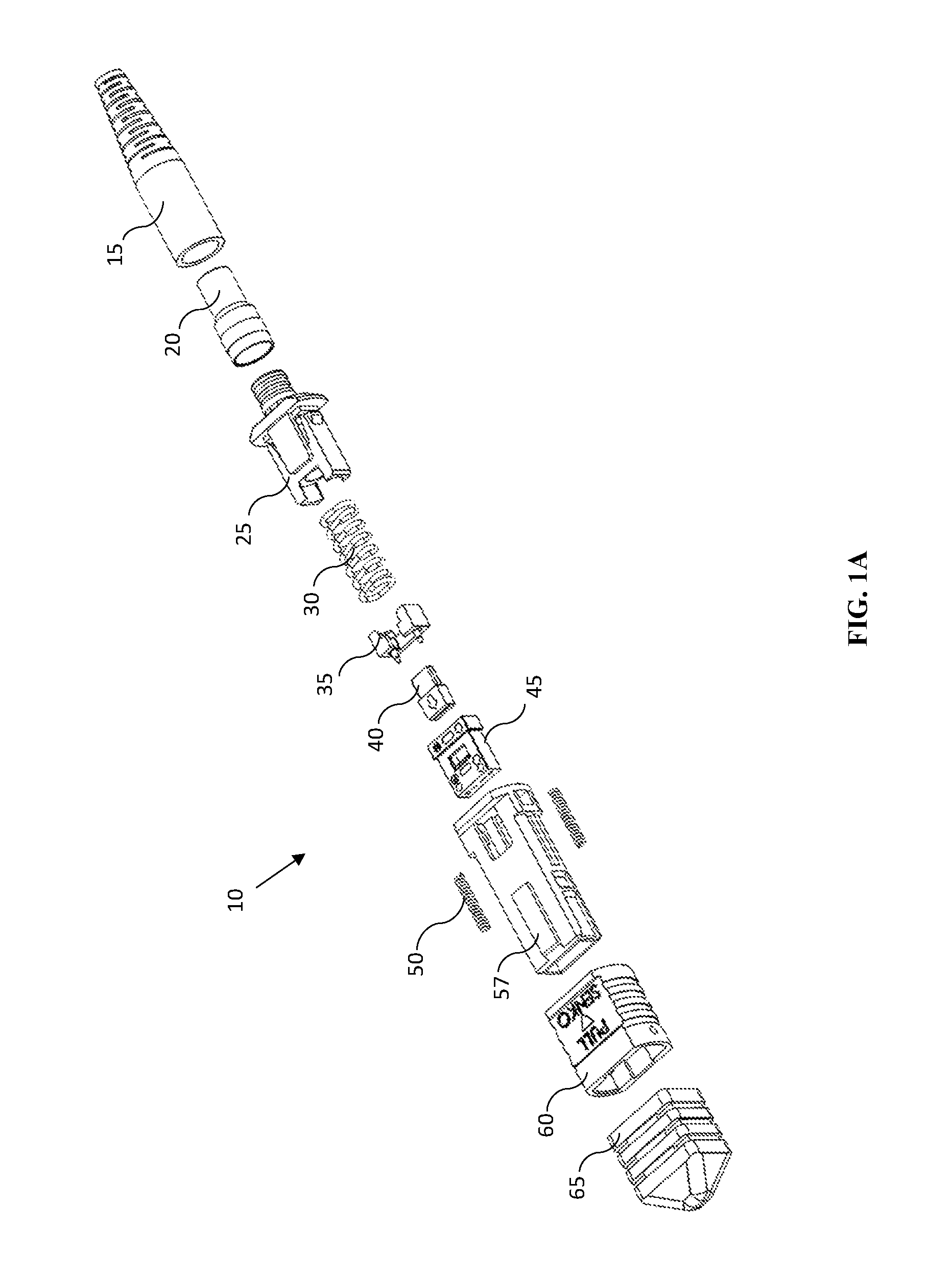
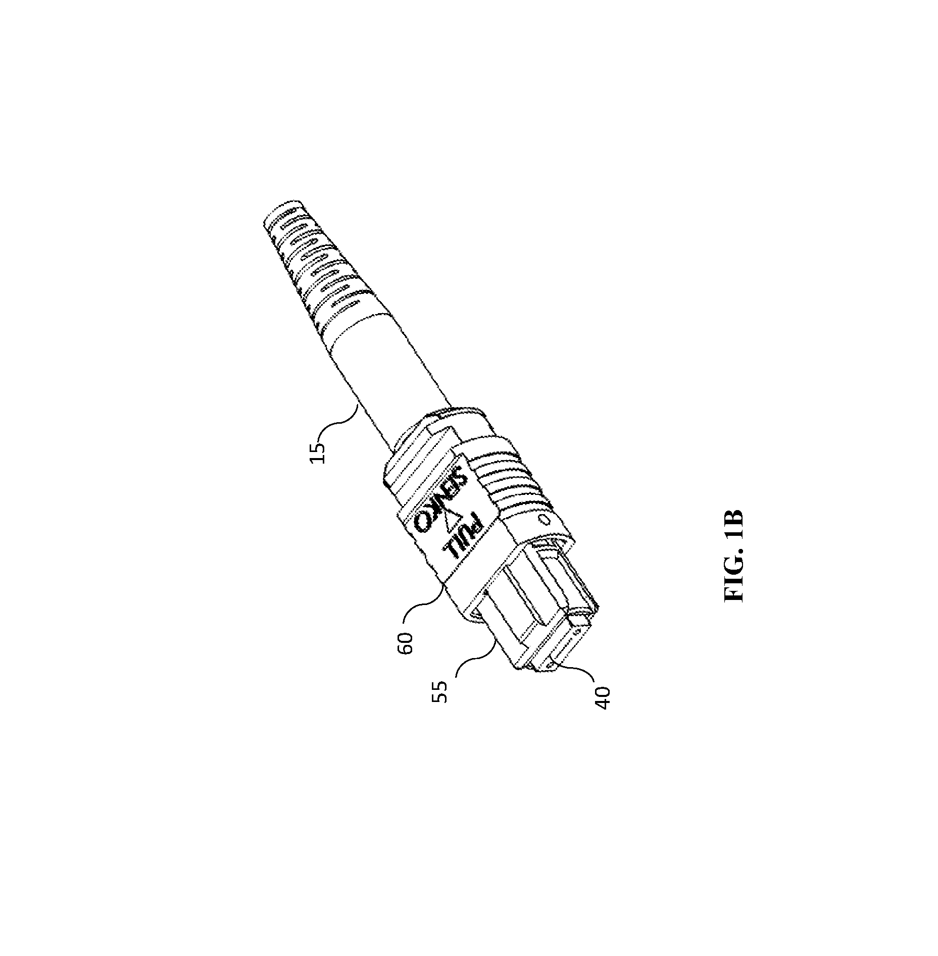
FIGS. 1A and 1B depict an exploded perspective view and an assembled perspective view, respectively, of an MPO optical connector according to an embodiment.
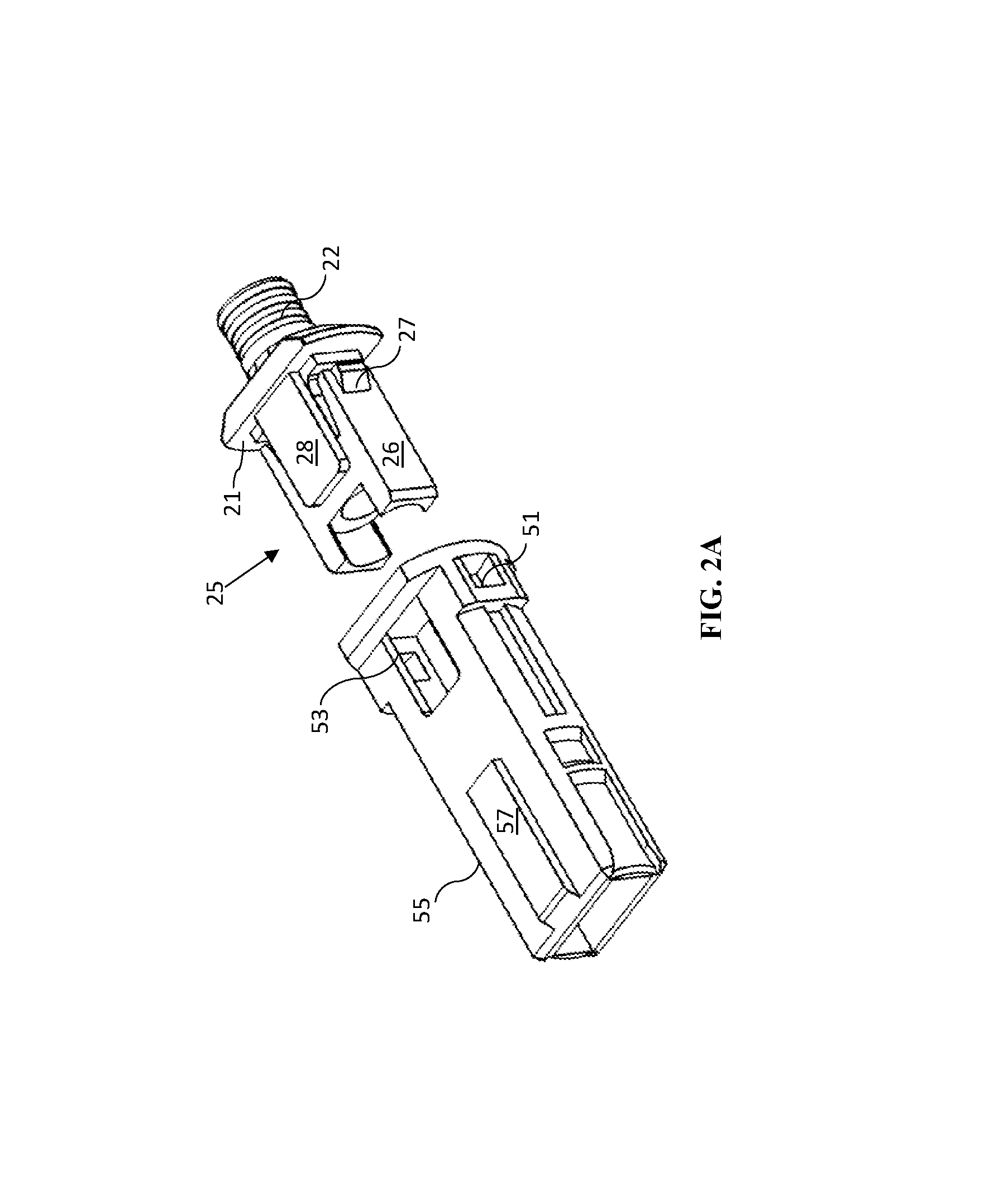
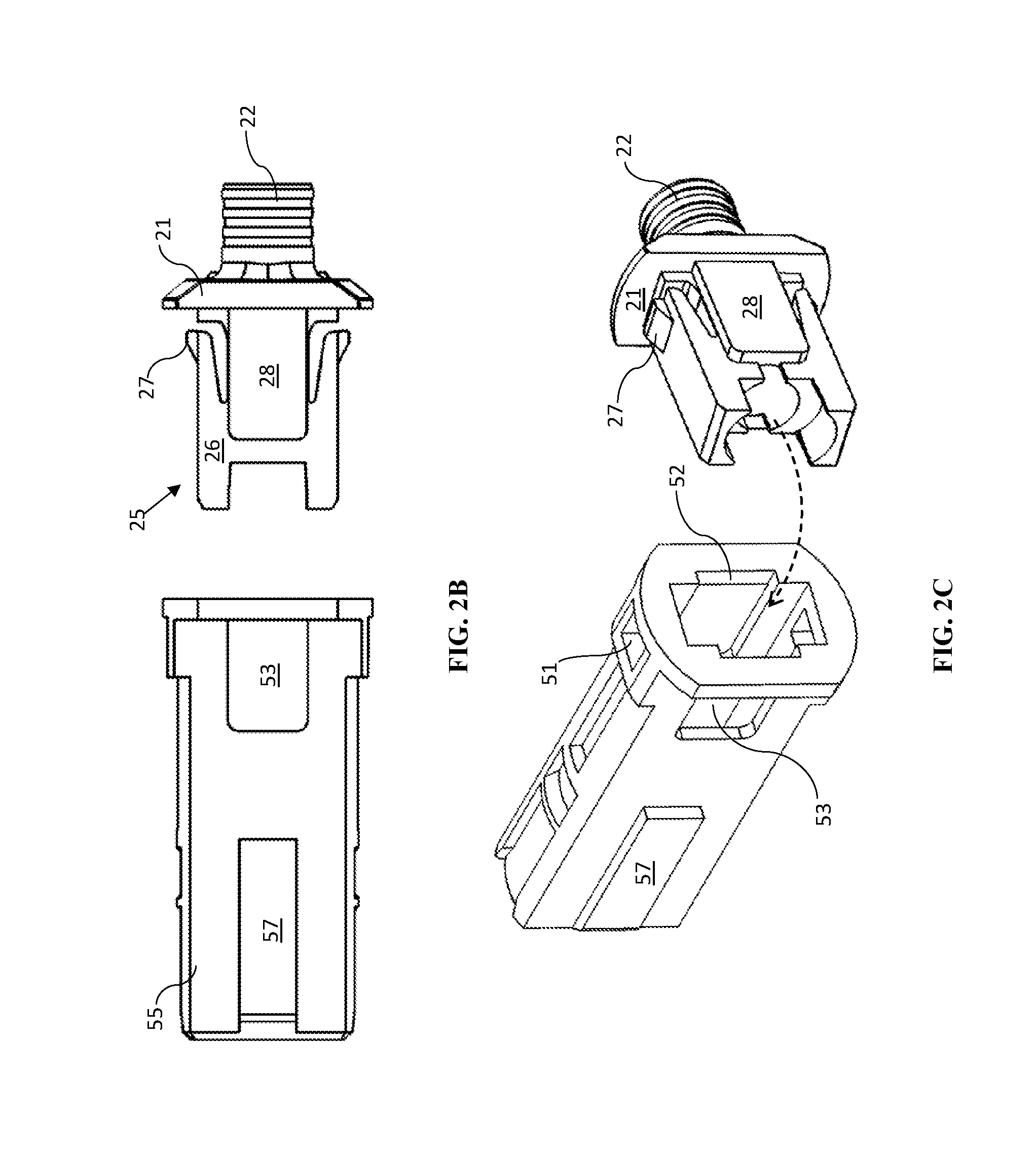
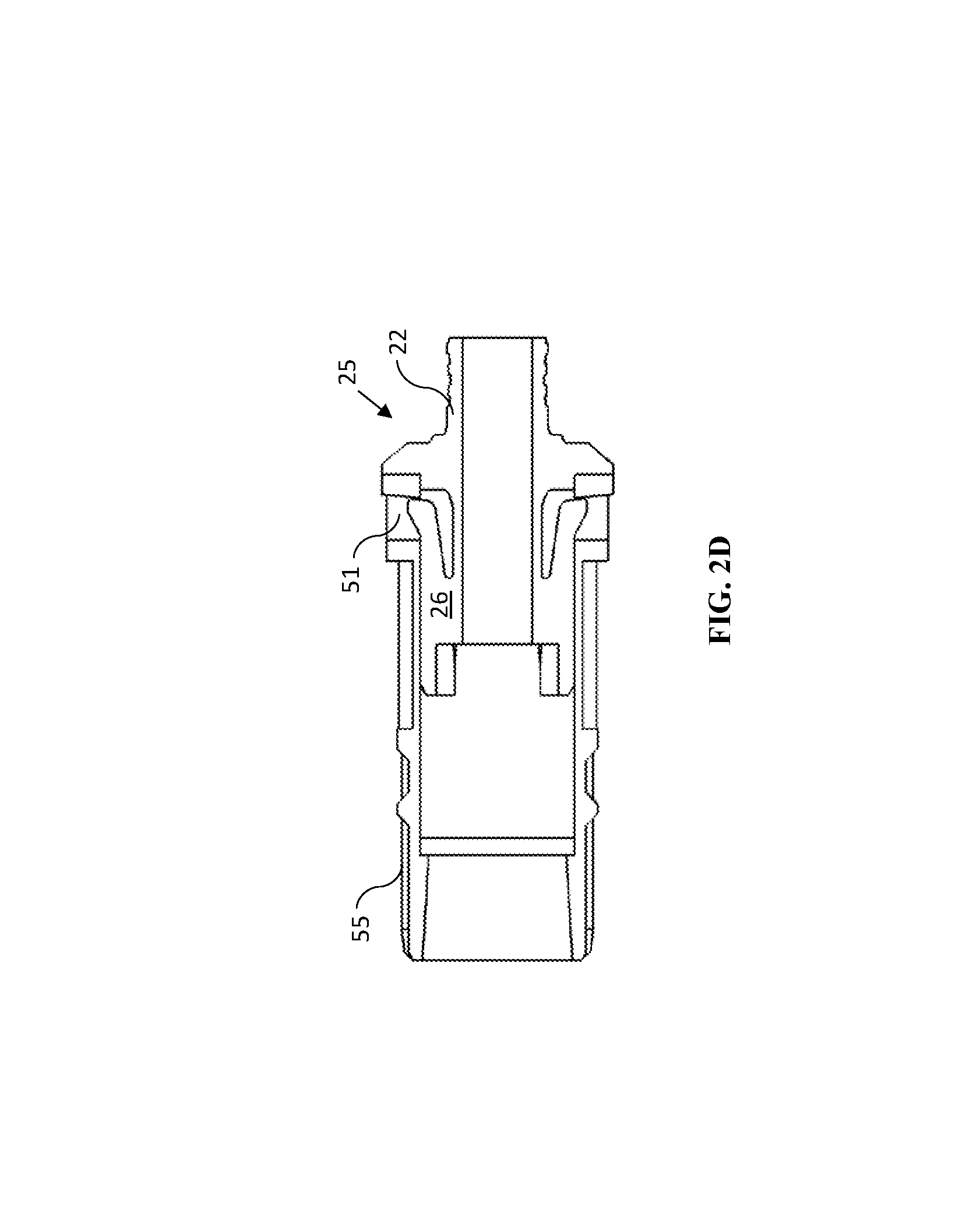
FIGS. 2A, 2B, 2C, and 2D depict a backpost and housing combination for use in the MPO optical connector of FIGS. 1A and 1B. FIG. 2A is an exploded perspective view, FIG. 2B is a side view, FIG. 2C is a perspective view looking into the housing, and FIG. 2D is a cross-sectional view of an assembled backpost and housing.
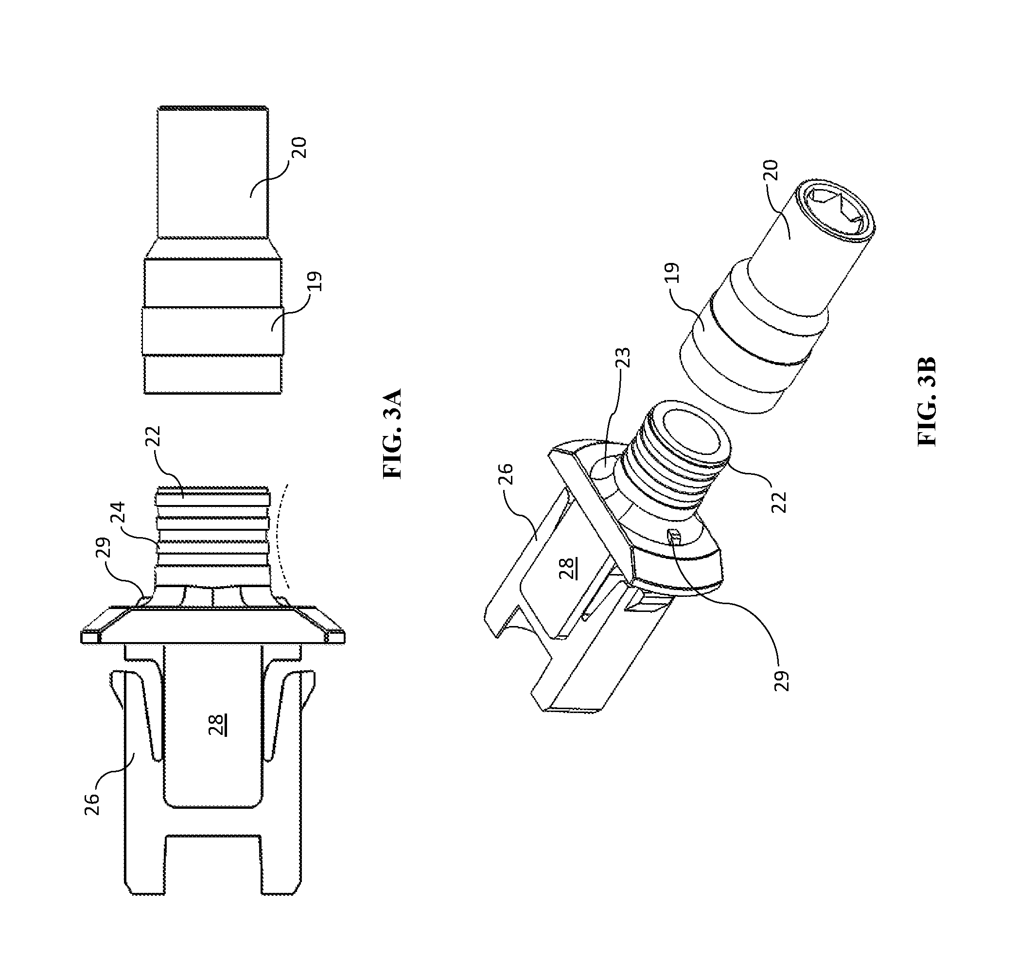
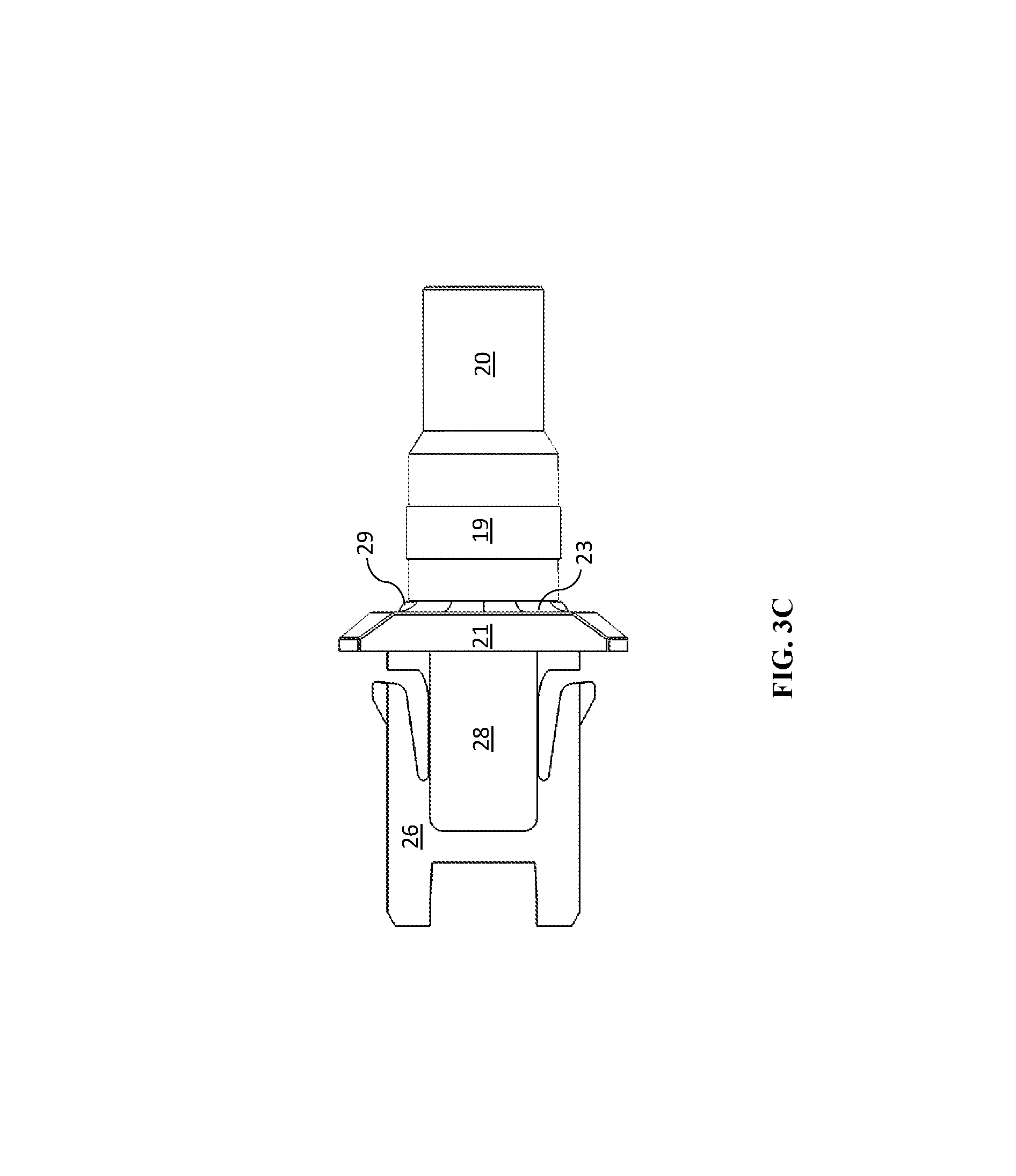
FIGS. 3A, 3B, 3C depict a backpost and a crimp ring for use in the MPO connector of FIGS. 1A and 1B. FIG. 3A is a side view, FIG. 3B is a perspective view with parts separated, and FIG. 3C is a side view assembled of the backpost of crimp ring.
FIGS. 4A and 4B are cross-sectional views of a backpost and crimp ring before and after crimping.
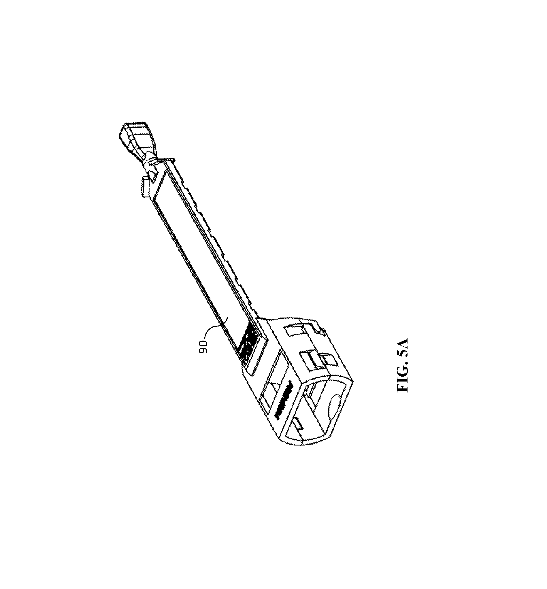
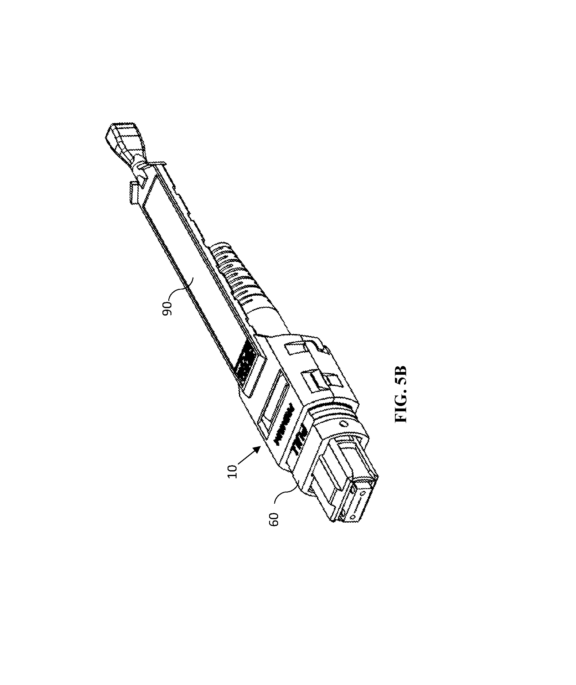
FIGS. 5A and 5B depict a pull-tab (FIG. 5A) and a pull-tab assembled on an MPO connector (FIG. 5B).
FIG. 6 depicts a prior art connector comprising a conventional backpost;
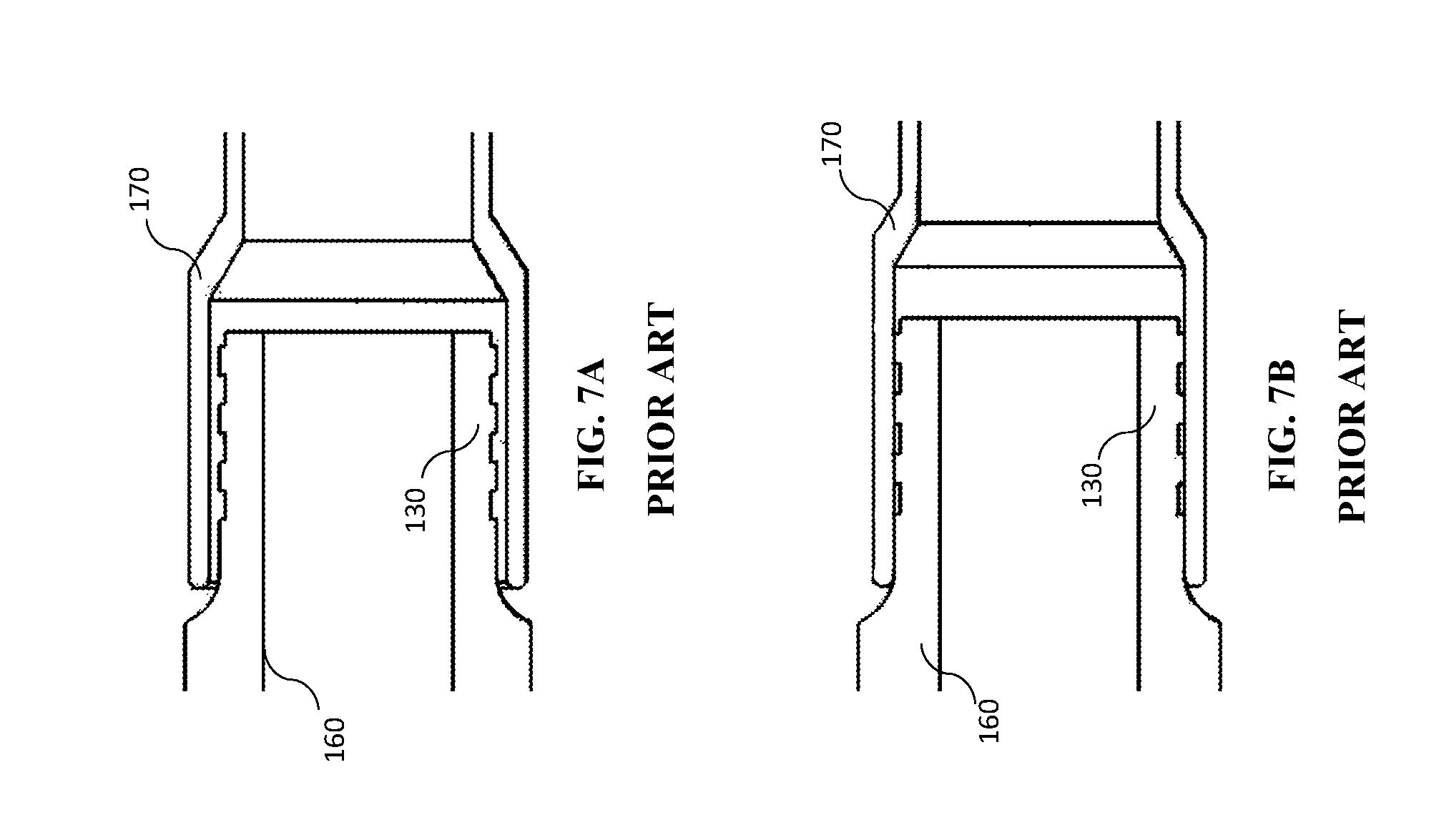
FIG. 7A depicts the neck of a prior art back post received in a crimp ring prior to the crimp ring being crimped onto the neck; and
FIG. 7B depicts the crimp ring and neck of FIG. 7A after the crimp ring has been crimped onto the neck.
DETAILED DESCRIPTION
As used herein, the term "optical fiber" is intended to apply to all types of single mode and multi-mode light waveguides, including one or more bare optical fibers, coated optical fibers, loose-tube optical fibers, tight-buffered optical fibers, ribbonized optical fibers, bend performance optical fibers, bend insensitive optical fibers, nanostructured optical fibers or any other expedient for transmitting light signals. A multi-fiber optic cable includes a plurality of the optical fibers. While the following description is directed towards MPO adapters and MPO connectors with MT optical ferrules, the embodiments described may be applicable to other connectors and ferrule types as well. In the description below, the distal direction is toward the connection of the optical fiber while the proximal direction is toward the cable end on the connector.
For connection of multiple fiber optic cables together or with other devices, the terminal end of a cable may include the MPO connector 10 as represented in FIGS. 1A and 1B. A connector 10 may include a housing 55 configured to hold a ferrule 45 that may be a multiple-fiber ferrule, urged towards a distal (connection) end of the housing by biasing member 30 and backpost 25. In use, a fiber optic cable is attached to the proximal end of connector 10, extending from cable boot 15.
The connector 10 may include a displaceable outer housing member 60 that may be slidably disposed about the housing 55 adjacent the distal end of the connector 10. To provide for a pre-determined alignment of fiber optic cables within an adapter or other connection, the housing 55 may include an alignment key 57 that is configured to fit within a keying slot of an adapter. The outer housing 60 may also slide along alignment key 57. The outer housing 60 may be biased towards the distal end of the connector via springs 50 or alternative types of biasing devices. An optional dust cap 65 fits over the distal end of connector 10 to protect the ferrule and the optical fibers contained therein when the connector is not connected to a mating connector or other device.
The optical connector 10 further includes a pin retainer 35 having a pair of pins that extend into the ferrule 45. Depending on whether the connector is configured as a male, female, or reconfigurable connector, guide pins may extend through the ferrule or the ferrule will have receiving apertures to accommodate guide pins from a mating connector. The biasing member 30, depicted in this embodiment as a spring, may be disposed between the backpost 25 and the pin retainer 35 to bias the ferrule 45 distally within the housing 55. Such biasing provides a biased mating of ferrule ends when the connector 10 is mated in an adapter or other connection to thereby hold the mated ferrule ends in contact with one another. An optional ferrule boot 40 is provided for fiber organization as the fibers extend into ferrule 45.
A fiber optic cable may be retained with the back post 25 by means of a crimp ring 20, or other type of detainment connector. A connector such as ring 20 may be crimped to the back post as well as to a cable sheathing (e.g., aramid fiber sheathing) of the cable to thereby prevent the cable from being pulled away from the backpost 25. The boot 15 is positioned over the crimped connection, providing support to an optical cable extending therethrough. The boot may be shaped to include an angle for connectors that will be subject to side loading to orient the cable 90 degrees from the connection direction.
More detailed views of the housing 55 and the backpost 25 are represented in FIGS. 2A, 2B, 2C, and 2D. As seen in FIG. 2A, the backpost 25 includes a flange 21 that connects to a ridged neck 22 through a fillet 23. Ridges 24 assist in retaining the aramid fiber sheathing of the optical cable on the neck 22. A pair of proximally-extending latch arms 26 include latch projections 27 for mating in proximal apertures 51 of the housing 55. Through the use of proximally-extending latch arms 26, the connector becomes a "reverse-latch" connector in that the connector latches adjacent to flange 21. In contrast to the inventive reverse-latch backpost 25, a conventional connector 100 with a conventional backpost 150 is depicted in FIG. 6. As seen in FIG. 6, the conventional backpost includes a pair distally-extending hooked legs 120. In particular, stress is concentrated at leg tip 150 which may break more easily in a side-loading condition. The shape of the proximally-extending latch arms and the latch projections spreads stress from an applied load, particularly a side load, throughout the entire arm, increasing the force that the optical connector is able to withstand. Further, the force exerted on the latching arms is changed from a shear stress to a compressive stress; as materials typically can withstand a greater compressive stress than shear stress, this enhances the overall strength of the connector. It is understood that the expression "reverse latch" is the opposite latch direction, that is, proximally-extending latch arms, to the conventional distally-extending latch arms depicted in FIG. 6.
To further increase the load capacity of the connector, one or more strengthening ribs 28 are positioned between the latching arms 26 on the backpost 25. The strengthening rib(s) is/are inserted into one or more corresponding grooves 52 within the housing 55, best seen in FIG. 2C. Optionally, one or more windows 53 are positioned approximately coextensive with the ribs 28 when the backpost is seated with the housing 55, FIG. 2D. Consequently, the window is also substantially coextensive with groove 52 that accommodates the rib 28. Alternatively, the housing may include grooves 52 enclosed within the housing 55, without windows. The strengthening ribs 28 increase the side load capacity of the connector. Further increasing the side load capacity is the window 53 which provides additional support to the strengthening rib 28 when the rib is seated within the window.
Another way to increase the strength of the optical connector is to increase the pull-out strength of the connection between the optical fiber cable and the backpost. As seen in FIGS. 3A, 3B, and 3C, several features ensure the proper positioning of an optical fiber cable on the backpost and ensure proper positioning of a crimp ring and enhanced crimp strength to increase the pull-out strength. As discussed above, ridges 24 on backpost neck 22 assist in retaining the aramid fiber sheathing of the optical cable. The neck 22 has a curved profile, in an approximately concave shape, as seen by the curved dashed line in FIG. 3A. The curved profile provides additional area in which to accommodate the aramid fiber between the neck and the crimp ring 20 and, as discussed below, results in an angled crimp as seen by the dashed line 17 with increased pull-out strength. Interacting with the curved-profile neck 22 is stepped crimp ring 20, which includes stepped region 19. During crimping, the greater height of stepped region 19 makes it the first area to be deformed; it will consequently undergo a greater deformation, ensuring a stronger hold on the aramid fiber from an optical cable being terminated by connector 10. In contrast, FIGS. 7A and 7B show a conventional crimp on a conventional backpost 160 with a straight-profile neck 130. During crimping, the deformation of the crimp ring 170 is uniform, resulting in a straight-line crimp profile as seen in FIG. 7B.
To ensure that the crimp ring is not positioned too far distally on the backpost 25, stopping protrusions 29 are provided on fillet 23, preventing the crimp ring from damaging the backpost fillet 23. As seen in FIG. 3C, a properly-positioned crimp ring 20 covers the entire neck region 22 with protrusions 29 preventing the crimp ring from being pushed too far forward on the fillet 23 that leads into flange 21 of backpost 25.
FIGS. 4A and 4B depict the stepped crimp ring 20 on curved-profile neck 22 before crimping, FIG. 4A, and after crimping, FIG. 4B. Before crimping, raised step 19 is clearly visible; after crimping, as seen in FIG. 4B, it is substantially flattened by the crimping force, creating an angled crimp line 17 caused by the curved neck 22 and the crimp ring 20. This angled crimp resists pull-out of an optical fiber cable.
Various accessories may be added to the basic optical connector such as the pull tab 90 of FIGS. 5A and 5B. In various applications, such as optical back planes, connectors are densely clustered at a chassis, making it difficult to insert or remove an individual connector 10. Pull tab 90 includes two sections that snap fit over outer housing 60, permitting a user to remotely slide outer housing 60 in a proximal direction to remove the connector 10.
Various parts, components or configurations described with respect to any one embodiment above may also be adapted to any others of the embodiments provided. This disclosure is not limited to the particular systems, devices and methods described, as these may vary. The terminology used in the description is for the purpose of describing the particular versions or embodiments only, and is not intended to limit the scope.
In the above detailed description, reference is made to the accompanying drawings, which form a part thereof. In the drawings, similar symbols typically identify similar components, unless context dictates otherwise. The illustrative embodiments described in the detailed description, drawings, and claims are not meant to be limiting. Other embodiments may be used, and other changes may be made, without departing from the spirit or scope of the subject matter presented herein. It will be readily understood that the aspects of the present disclosure, as generally described herein, and illustrated in the figures, can be arranged, substituted, combined, separated, and designed in a wide variety of different configurations, all of which are explicitly contemplated herein.
The present disclosure is not to be limited in terms of the particular embodiments described in this application, which are intended as illustrations of various aspects. Many modifications and variations can be made without departing from its spirit and scope, as will be apparent to those skilled in the art. Functionally equivalent methods and apparatuses within the scope of the disclosure, in addition to those enumerated herein, will be apparent to those skilled in the art from the foregoing descriptions. Such modifications and variations are intended to fall within the scope of the appended claims. The present disclosure is to be limited only by the terms of the appended claims, along with the full scope of equivalents to which such claims are entitled. It is to be understood that this disclosure is not limited to particular methods, reagents, compounds, compositions or biological systems, which can, of course, vary. It is also to be understood that the terminology used herein is for the purpose of describing particular embodiments only, and is not intended to be limiting.
As used in this document, the singular forms "a," "an," and "the" include plural references unless the context clearly dictates otherwise. Unless defined otherwise, all technical and scientific terms used herein have the same meanings as commonly understood by one of ordinary skill in the art. Nothing in this disclosure is to be construed as an admission that the embodiments described in this disclosure are not entitled to antedate such disclosure by virtue of prior invention. As used in this document, the term "comprising" means "including, but not limited to."
While various methods, and devices are described in terms of "comprising" various components or steps (interpreted as meaning "including, but not limited to"), the compositions, methods, and devices can also "consist essentially of" or "consist of" the various components and steps, and such terminology should be interpreted as defining essentially closed-member groups.
With respect to the use of substantially any plural and/or singular terms herein, those having skill in the art can translate from the plural to the singular and/or from the singular to the plural as is appropriate to the context and/or application. The various singular/plural permutations may be expressly set forth herein for sake of clarity.
It will be understood by those within the art that, in general, terms used herein, and especially in the appended claims (e.g., bodies of the appended claims) are generally intended as "open" terms (e.g., the term "including" should be interpreted as "including but not limited to," the term "having" should be interpreted as "having at least," the term "includes" should be interpreted as "includes but is not limited to," etc.).
Various of the above-disclosed and other features and functions, or alternatives thereof, may be combined into many other different systems or applications. Various presently unforeseen or unanticipated alternatives, modifications, variations or improvements therein may be subsequently made by those skilled in the art, each of which is also intended to be encompassed by the disclosed embodiments.
* * * * *
References
D00000
D00001
D00002
D00003
D00004
D00005
D00006
D00007
D00008
D00009
D00010
D00011
D00012
XML
uspto.report is an independent third-party trademark research tool that is not affiliated, endorsed, or sponsored by the United States Patent and Trademark Office (USPTO) or any other governmental organization. The information provided by uspto.report is based on publicly available data at the time of writing and is intended for informational purposes only.
While we strive to provide accurate and up-to-date information, we do not guarantee the accuracy, completeness, reliability, or suitability of the information displayed on this site. The use of this site is at your own risk. Any reliance you place on such information is therefore strictly at your own risk.
All official trademark data, including owner information, should be verified by visiting the official USPTO website at www.uspto.gov. This site is not intended to replace professional legal advice and should not be used as a substitute for consulting with a legal professional who is knowledgeable about trademark law.