Wind power generating device of transportation vehicle
Lee , et al. Oc
U.S. patent number 10,443,568 [Application Number 15/868,977] was granted by the patent office on 2019-10-15 for wind power generating device of transportation vehicle. The grantee listed for this patent is Shou-Hsun Lee, Chun-I Li. Invention is credited to Shou-Hsun Lee, Chun-I Li.


| United States Patent | 10,443,568 |
| Lee , et al. | October 15, 2019 |
Wind power generating device of transportation vehicle
Abstract
A wind power generating device includes: a power source assembly and a power generating assembly, the power source assembly including a brake disc and a brake actuator, the brake actuator being configured to swing around a lever fulcrum, and the brake actuator being provided with a wind collector on one side with respect to the lever fulcrum to receive wind force and a brake pad corresponding to the brake disc on the other side such that when the wind collector swings backward because of wind force from the front, the brake pad relatively swings frontward to touch the brake disc by leverage so as to apply a brake force to a rotor component of the power source assembly, and the power generating assembly including a maximum power point tracker (MPPT) such that the generated electric energy is stored to an energy storage element under control of the MPPT.
| Inventors: | Lee; Shou-Hsun (Tainan, TW), Li; Chun-I (Tainan, TW) | ||||||||||
|---|---|---|---|---|---|---|---|---|---|---|---|
| Applicant: |
|
||||||||||
| Family ID: | 61163600 | ||||||||||
| Appl. No.: | 15/868,977 | ||||||||||
| Filed: | January 11, 2018 |
Prior Publication Data
| Document Identifier | Publication Date | |
|---|---|---|
| US 20190093631 A1 | Mar 28, 2019 | |
Foreign Application Priority Data
| Sep 25, 2017 [TW] | 106132705 A | |||
| Current U.S. Class: | 1/1 |
| Current CPC Class: | F03D 7/041 (20130101); F03D 7/0248 (20130101); F03D 9/32 (20160501); F03D 7/0244 (20130101); F03D 9/25 (20160501); Y02E 10/725 (20130101); F03D 9/11 (20160501); Y02E 10/723 (20130101); F05B 2260/902 (20130101); F05B 2270/20 (20130101); Y02E 10/728 (20130101); F05B 2270/3201 (20130101) |
| Current International Class: | F03D 7/02 (20060101); F03D 9/11 (20160101); F03D 9/25 (20160101); F03D 9/32 (20160101); F03D 7/04 (20060101) |
References Cited [Referenced By]
U.S. Patent Documents
| 2112900 | April 1938 | McColly |
| 3918556 | November 1975 | Nagatomo |
| 5701977 | December 1997 | Vrevich |
| 8004232 | August 2011 | Schultz |
| 8710691 | April 2014 | Haddad |
| 9024463 | May 2015 | Boone |
Assistant Examiner: Reitz; Michael K.
Attorney, Agent or Firm: AEON Law, PLLC Philipp; Adam L. K. Garthwaite; Martin S.
Claims
What is claimed is:
1. A wind power generating device, comprising: a power source assembly which includes a rotor component and a brake component, the rotor component including a blade and a drive shaft, the blade being served to receive a wind force from a front side to rotate, the drive shaft being in driven connection with the blade to transfer a rotary motion of the blade, the brake component including a brake disc and a brake actuator, the brake disc being positioned at a back side of the blade and being configured to interlink with the blade so as to rotate together with the blade, the brake actuator being provided with a lever, a wind collector and a brake pad, the lever being provided with a lever fulcrum in such a manner that the wind collector is provided at one end of the lever, the brake pad is provided at the other end of the lever, the lever fulcrum of the lever is located between the wind collector and the brake pad, and a wind force applying on the wind collector swings the lever by taking the lever fulcrum as the fulcrum, wherein a brake surface of the brake pad faces forward a direction where a wind is from so as to touch and brake the brake disc in such a manner that the wind collector and the brake pad move in opposite directions by taking the lever fulcrum as a fulcrum such that when the wind collector swings backward with a pushing of the wind force from the front side, the brake pad relatively swings forward to touch and brake the brake disc by means of the leverage of the brake actuator so as to apply a brake force in such a manner that the rotor component is braked; and a power generating assembly, which includes a power generating element, a maximum power point tracker (MPPT) and an energy storage element which are electrically connected to each other, the power generating element being in drive connection with the drive shaft such that the power generating element is driven by the drive shaft to generate electric energy, and the generated electric energy is stored to the energy storage element under the control of the maximum power point tracker.
2. The wind power generating device of claim 1, wherein the brake component further includes an elastic restoration part, the elastic restoration part being provided with one end connected to a fixed mount and the other end connected to the brake actuator such that an elastic restoring force applied to the brake actuator makes the wind collector of the brake actuator swing forward to return to an initial position and make the brake pad of the brake actuator swing backward to release a brake.
3. The wind power generating device of claim 2, wherein the brake component further includes an adjuster which is connected between a fixed mount and the elastic restoration part, the adjuster being configured to change the relative position between the elastic restoration part and the fixed mount so as to adjust the elastic restoring force of the elastic restoration part applied to the brake actuator.
4. The wind power generating device of claim 3, wherein the adjuster is adjustably screwed to the fixed mount to adjust the elastic restoring force of the elastic restoration part applied to the brake actuator by being screwed in or screwed out with respect to the fixed mount to adjust a relative position between the elastic restoration part and the fixed mount.
5. The wind power generating device of claim 1, wherein the wind collector is in flat plate shape.
6. The wind power generating device of claim 1, wherein the wind collector is in spoon shape.
7. The wind power generating device of claim 1, wherein the blade is a scroll type blade or a screw type blade or a spherical blade or a Venetian blade.
8. The wind power generating device of claim 1, wherein the brake actuator is configured to stay still facing to a wind force when the wind force is weaker than 90 km/hr.
9. A transportation vehicle, comprising the wind power generating device as claimed in any one of the claims 1 to 8.
Description
FIELD OF THE INVENTION
The present invention relates to a wind power generating device, and more particularly relates to a wind power generating device having a braking function for a transportation vehicle.
BACKGROUND OF THE INVENTION
Based on the willingness to make good use of energy power, a wind power generating device to be mounted on a transportation vehicle, such as a scooter or a car, has been developed such that, when the transportation vehicle is running, the generated wind power accompanying the wind flow can be converted into kinetic energy and then further be converted into electric energy.
The structure of this kind of wind power generating device mainly includes a blade, a drive shaft and a power generator, the blade being able to be driven by wind power to rotate thereby converting kinetic power of the wind into mechanical energy of the drive shaft so as to drive the power generator to rotate to generate power.
However, when the running speed of the transportation vehicle becomes so fast that the wind flow speed become too fast, the blade and the power generator can burn up and break because of a too high speed rotating. Therefore, an improvement for the wind power generating device of transportation vehicle is needed.
SUMMARY OF THE INVENTION
Therefore, an objective of the present invention is to provide a wind power generating device with self-adjusting braking mechanism.
In order to achieve the above, the present invention provides a wind power generating device, comprising: a power source assembly which includes a rotor component and a brake component, the rotor component including a blade and a drive shaft, the blade being served to receive the wind force from the front side to rotate, the drive shaft being in driven connection with the blade to transfer the rotary motion of the blade, the brake component including a brake disc and a brake actuator, the brake disc being positioned at the back side of the blade and being configured to interlink with the blade so as to rotate together with the blade, the brake actuator being configured to swing around a lever fulcrum, and the brake actuator being configured with a wind collector on one side with respect to the lever fulcrum to receive the wind force from the front side and a brake pad corresponding to the brake disc on the other side with respect to the lever fulcrum such that when the wind collector swings backward with the pushing of the wind force from the front side, the brake pad relatively swings frontward to touch the brake disc by means of the leverage of the brake actuator so as to apply a brake force in such a manner that the rotor component is braked; and a power generating assembly, which includes a power generating element, a maximum power point tracker (MPPT) and an energy storage element which are electrically connected to each other, the power generating element being in drive connection with the drive shaft such that the power generating element is driven by the drive shaft to generate electric energy, and the generated electric energy is stored to the energy storage element under the control of the maximum power point tracker.
In one embodiment of the present invention, a wind power generating device is provided that the brake component further includes an elastic restoration part, the elastic restoration part is provided with one end connected to a fixed mount and the other end connected to the brake actuator such that an elastic restoring force applied to the brake actuator makes the wind collector of the brake actuator swing frontward to return to an initial position and make the brake pad of the brake actuator swing backward to release a brake.
In one embodiment of the present invention, a wind power generating device is provided that the brake component further includes an adjuster which is connected between a fixed mount and the elastic restoration part, the adjuster being configured to change the relative position between the elastic restoration part and the fixed mount so as to adjust the elastic restoring force of the elastic restoration part applied to the brake actuator.
In one embodiment of the present invention, a wind power generating device is provided that the adjuster is adjustably screwed to the fixed mount to adjust the elastic restoring force of the elastic restoration part applied to the brake actuator by being screwed in or screwed out with respect to the fixed mount to adjust a relative position between the elastic restoration part and the fixed mount.
In one embodiment of the present invention, a wind power generating device is provided that the wind collector is in flat plate shape.
In one embodiment of the present invention, a wind power generating device is provided that the wind collector is in spoon shape.
In one embodiment of the present invention, a wind power generating device is provided that the blade is a scroll type blade or a screw type blade or a spherical blade or a Venetian blade.
In one embodiment of the present invention, a wind power generating device is provided that the brake actuator is configured to stay still facing to a wind force when the wind force is weaker than 90 km/hr.
In one embodiment of the present invention, a transportation vehicle is provided comprising the wind power generating device as mentioned above.
By means of the technology used by the present invention, when the rotor component rotates at a wind speed which exceeds a specified value, the wind collector is pushed by the wind force to swing backward such that the brake pad moves relatively to swing frontward to touch the brake disc positioned in front of the brake pad so as to apply a brake force in such a manner that the rotor component is braked. Moreover, a maximum power point tracker (MPPT) is configured to ensure the power supply to be kept at the highest efficiency. Preferably, the adjuster is provided to adjust the relative position between the elastic restoration part and the fixed mount so as to adjust the elastic restoring force of the elastic restoration part applied to the brake actuator.
BRIEF DESCRIPTION OF THE DRAWINGS
FIG. 1 is a perspective view illustrating a wind power generating device according to one embodiment of the present invention.
FIG. 2 is a top view illustrating the wind power generating device according to the embodiment of the present invention having the brake pad relatively swung frontward to touch the brake disc.
FIG. 3 is a perspective view illustrating a wind collector of a wind power generating device according to another embodiment of the present invention.
FIG. 4 is a schematic sectional view illustrating a power generating element of the wind power generating device according to the embodiment of the present invention.
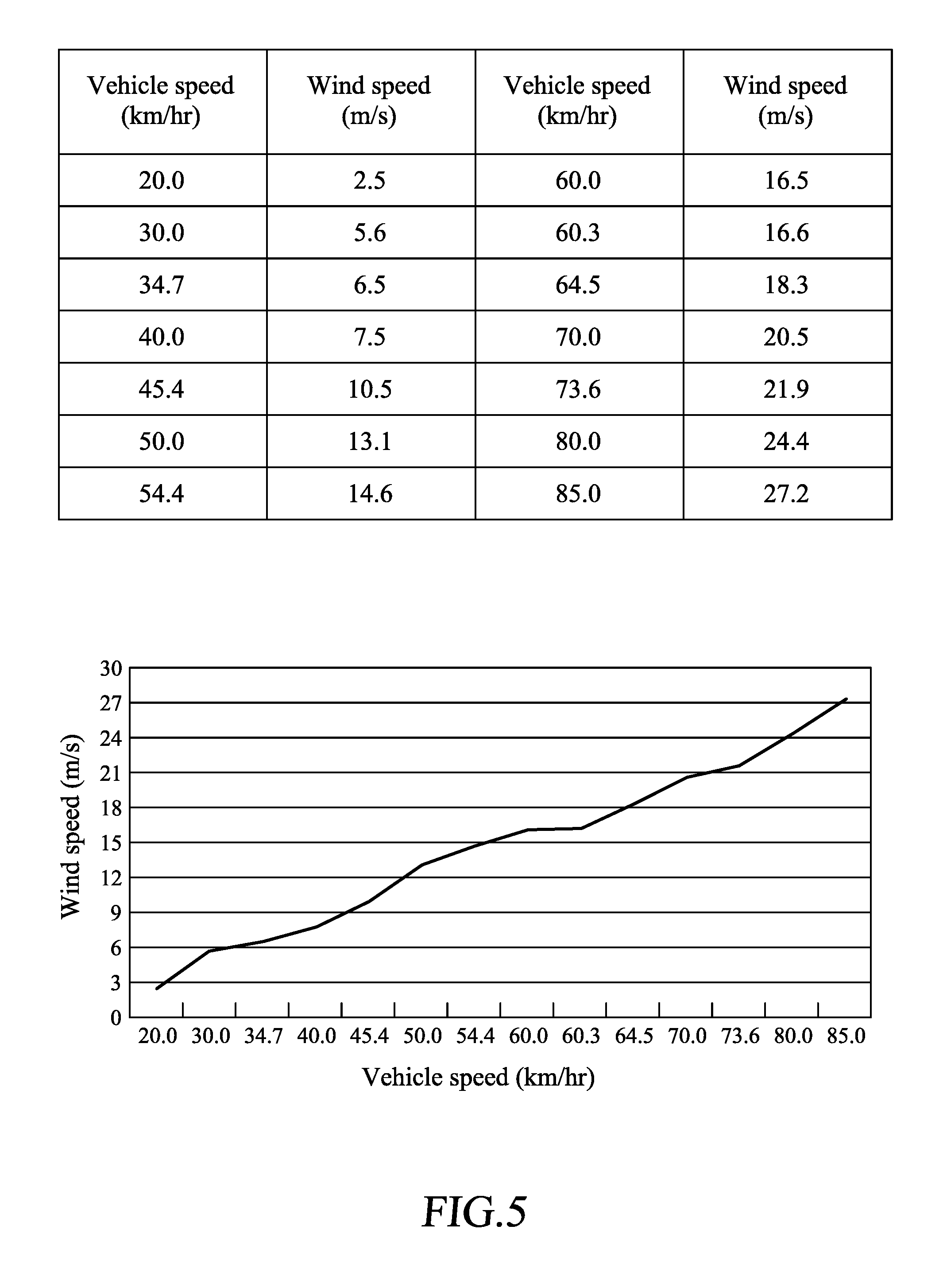
FIG. 5 is a correlation table-chart of the correlation between wind speed and vehicle speed of the wind power generating device according to the embodiment of the present invention.
FIG. 6 is a correlation table-chart of the correlation between generated power voltage and wind speed of the wind power generating device according to the embodiment of the present invention.
FIG. 7 is a correlation table-chart of the correlation between generated power current and wind speed of the wind power generating device according to the embodiment of the present invention.
FIG. 8 is a correlation table-chart of the correlation between electrical power and wind speed of the wind power generating device according to the embodiment of the present invention.
FIG. 9 is a correlation chart of the correlation between power and wind speed of the wind power generating device according to the embodiment of the present invention.
DETAILED DESCRIPTION OF THE PREFERRED EMBODIMENTS
The preferred embodiments of the present invention are described in detail below with reference to FIG. 1 to FIG. 9. The description is used for explaining the embodiments of the present invention only, but not for limiting the scope of the claims.
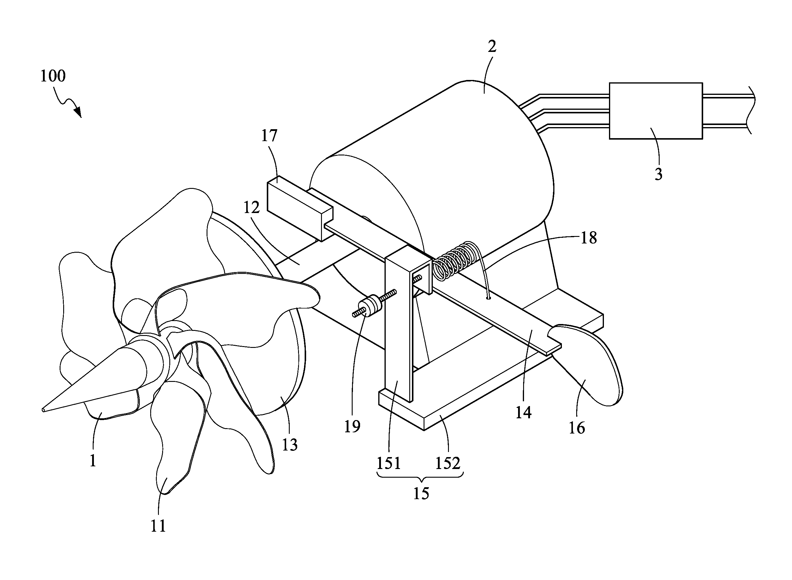
As shown in FIG. 1, a wind power generating device 100 according to a first embodiment of the present invention includes a power source assembly 1 and a power generating assembly.
In more detail, the wind power generating device of the present invention is to be used by being mounted on a transportation vehicle, the transportation vehicle including electric car, electric scooter, electric bicycle, electric train, boat, flight vehicle, etc. As shown in FIG. 1, the power source assembly 1 includes a rotor component and a brake component. The rotor component including a blade 11 and a drive shaft 12, the blade 11 which is a scroll type blade being served to receive the wind force from the front side to rotate, the drive shaft 12 being in driven connection with the blade 11 to transfer the rotary motion of the blade 11. Of course, the present invention is not limited thereto. In the other embodiments, the blade can be a screw type blade or a spherical blade or a Venetian blade. The brake component includes a brake disc 13 and a brake actuator. The brake disc 13 is positioned at the back side of the blade 11 and is configured to interlink with the blade 11 so as to rotate together with the blade 11, the brake actuator being configured to swing around a lever fulcrum. In more detail, the brake actuator includes a lever 14 and a fixed mount 15, the fixed mount 15 being disposed at the power generating assembly, and including a support 151 which is approximately in inverted L shape and a base plate 152 being connected under the support 151. The lever 14 is arranged horizontally on the support 151 of the fixed mount 15, the point where the lever 14 is connected to the support 151 of the fixed mount 15 being served as the lever fulcrum. The brake actuator is provided with a wind collector 16 on one side with respect to the lever fulcrum to receive the wind force from the front side and a brake pad 17 corresponding to the brake disc 13 on the other side with respect to the lever fulcrum such that when the wind collector 16 swings backward with the pushing of the wind force from the front side, the brake pad 17 relatively swings frontward to touch the brake disc 13 by means of the leverage of the brake actuator so as to apply a brake force in such a manner that the rotor component is braked. Besides, a remarkable fact is that the brake actuator is configured to stay still facing to a wind force when the wind force is weaker than 90 km/hr. In detail, when the wind force is higher than 100 km/hr, the brake actuator is activated because of the wind force such that the whole wind power generating device is self-braking in such a manner that the higher the wind force is, the higher the brake force is. Of course, the present invention is not limited thereto. In other embodiments, the brake actuator can stay still facing to a wind force when the wind force is at other wind speeds, for example weaker than 60, or 70, or 80, or 100, or 110 km/hr. In addition, the lever fulcrum on the lever 14 is biased to the wind collector 16. In more detail, in this embodiment, the wind collector 16 is in flat plate shape. Of course, the present invention is not limited thereto. In another embodiment, as shown in FIG. 3, the wind collector 16a is in spoon shape with its concave side facing towards the front.
As shown in FIG. 1 and FIG. 2, in more detail, the brake component further includes an elastic restoration part 18. In this embodiment, the elastic restoration part 18 is a spring. The elastic restoration part is provided with one end connected to the fixed mount 15 and the other end connected to the lever 14 of the brake actuator such that an elastic restoring force applied to the brake actuator makes the wind collector 16 of the brake actuator swing frontward to return to an initial position and make the brake pad 17 of the brake actuator swing backward to release the brake. Preferably, the brake component further includes an adjuster 19 which is connected between the fixed mount 15 and the elastic restoration part 18, the adjuster 19 being configured to change the relative position between the elastic restoration part and the fixed mount so as to adjust the elastic restoring force of the elastic restoration part 18 applied to the brake actuator. In this embodiment, the adjuster 19 is adjustably screwed to the fixed mount 15 to adjust a relative position between the elastic restoration part 18 and the fixed mount 15 by being screwed in so as to tighten the elastic restoration part 18, or screwed out so as to loosen the elastic restoration part 18 with respect to the fixed mount 15 thereby adjusting the elastic restoring force of the elastic restoration part 18 applied to the brake actuator.
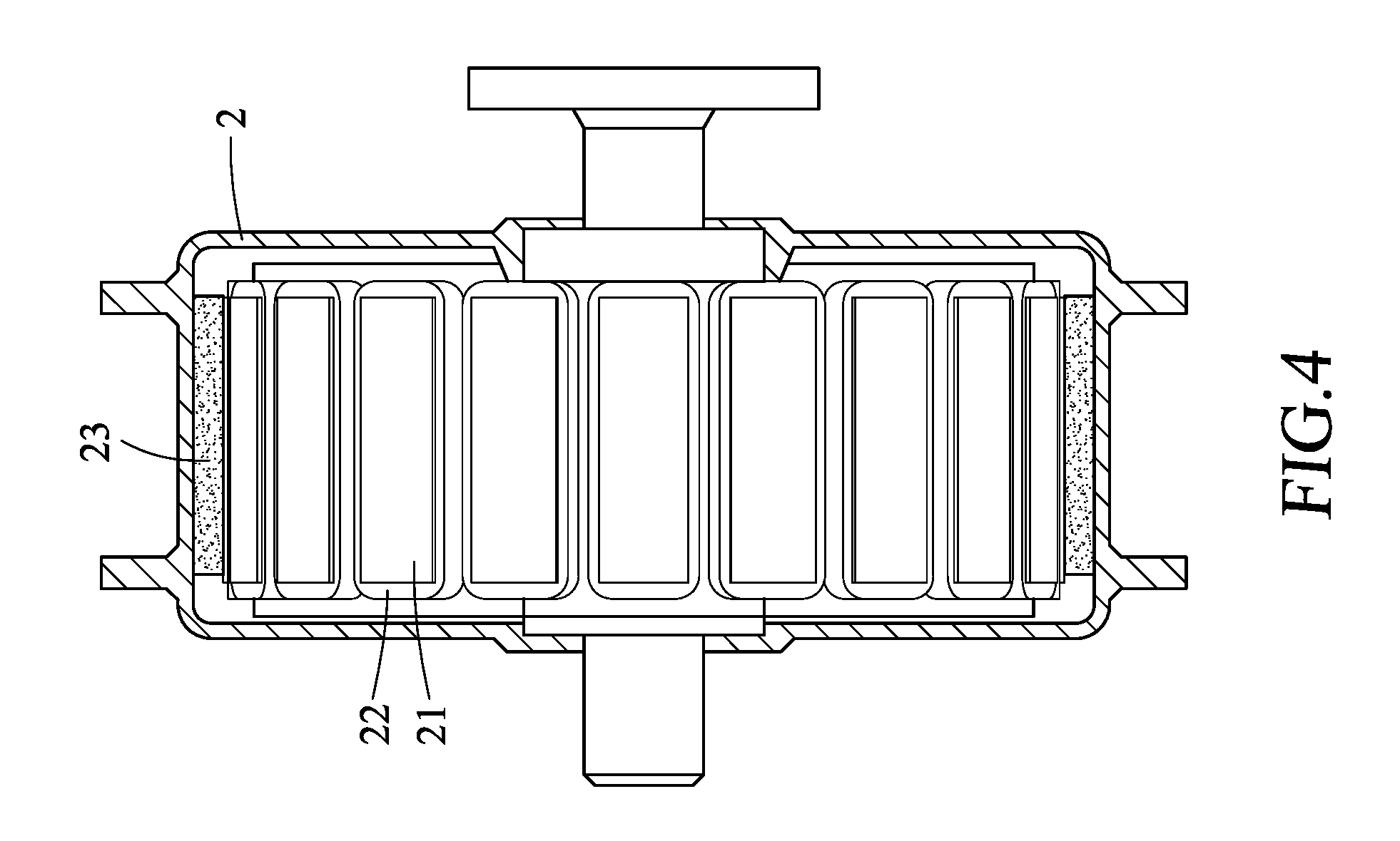
The power generating assembly includes a power generating element 2, a maximum power point tracker (MPPT) 3 and an energy storage element (not shown in the figures) which are electrically connected to each other. In more detail, as shown in FIG. 4, the power generating element 2, which is a power generator, is in drive connection with the drive shaft 12 and includes inner stator poles 21, coils 22 and permanent magnets 23 such that the power generating element 2 is driven by the drive shaft 12 to drive the coils 22 to generate electric energy, and the generated electric energy is stored to the energy storage element under the control of the maximum power point tracker. Thereby, the output voltage of the power generating element 2 can be DC 12V, or 24V, or 36V, or 48V, or 60V, or 72V, or 84V, or 96V. In more detail, the power generating element 2 is a single device which operates independently. In other embodiments, the power generating element 2 can also be a power generator set with multiple power generators used in parallel such that the power generation can be from 100 W used in parallel to more than 36000 W used in parallel.
As shown in FIG. 5 to FIG. 9, the wind power generating device of the present invention performs a very nice power generating efficiency, when the vehicle speed is at about 20 km/hr inducing a wind speed at more than 5 m/s.
The above description should be considered only as an explanation of the preferred embodiment of the present invention. A person with ordinary skill in the art can make various modifications to the present invention based on the scope of the claims and the above description. However, those modifications shall fall within the scope of the present invention.
* * * * *
D00000
D00001
D00002
D00003
D00004
D00005
D00006
D00007
D00008
D00009
XML
uspto.report is an independent third-party trademark research tool that is not affiliated, endorsed, or sponsored by the United States Patent and Trademark Office (USPTO) or any other governmental organization. The information provided by uspto.report is based on publicly available data at the time of writing and is intended for informational purposes only.
While we strive to provide accurate and up-to-date information, we do not guarantee the accuracy, completeness, reliability, or suitability of the information displayed on this site. The use of this site is at your own risk. Any reliance you place on such information is therefore strictly at your own risk.
All official trademark data, including owner information, should be verified by visiting the official USPTO website at www.uspto.gov. This site is not intended to replace professional legal advice and should not be used as a substitute for consulting with a legal professional who is knowledgeable about trademark law.