Spoke mounting arrangement
Lefebvre , et al. Oc
U.S. patent number 10,443,449 [Application Number 15/206,579] was granted by the patent office on 2019-10-15 for spoke mounting arrangement. This patent grant is currently assigned to Pratt & Whitney Canada Corp.. The grantee listed for this patent is Pratt & Whitney Canada Corp.. Invention is credited to Guy Lefebvre, John Pietrobon, Remy Synnott.


| United States Patent | 10,443,449 |
| Lefebvre , et al. | October 15, 2019 |
Spoke mounting arrangement
Abstract
A mid-turbine frame of a gas turbine engine has a structural ring assembly comprising an outer ring, an inner ring having a plurality of threaded bosses extending from a radially outer surface thereof, and a corresponding number of structural spokes interconnecting the inner ring to the outer ring. Each spoke has a radially inner threaded end threadably engaged in an associated one of the threaded bosses on the inner ring.
| Inventors: | Lefebvre; Guy (St-Bruno-de-Montarville, CA), Synnott; Remy (St-Jean-sur-Richelieu, CA), Pietrobon; John (Outremont, CA) | ||||||||||
|---|---|---|---|---|---|---|---|---|---|---|---|
| Applicant: |
|
||||||||||
| Assignee: | Pratt & Whitney Canada
Corp. (Longueuil, Quebec, CA) |
||||||||||
| Family ID: | 57881874 | ||||||||||
| Appl. No.: | 15/206,579 | ||||||||||
| Filed: | July 11, 2016 |
Prior Publication Data
| Document Identifier | Publication Date | |
|---|---|---|
| US 20170107856 A1 | Apr 20, 2017 | |
Related U.S. Patent Documents
| Application Number | Filing Date | Patent Number | Issue Date | ||
|---|---|---|---|---|---|
| 62196360 | Jul 24, 2015 | ||||
| 62196330 | Jul 24, 2015 | ||||
| Current U.S. Class: | 1/1 |
| Current CPC Class: | F01D 25/246 (20130101); F01D 25/162 (20130101); F05D 2260/31 (20130101); F05D 2260/30 (20130101); F05D 2230/60 (20130101) |
| Current International Class: | F01D 25/24 (20060101); F01D 25/16 (20060101) |
References Cited [Referenced By]
U.S. Patent Documents
| 3261587 | July 1966 | Rowley |
| 3403889 | October 1968 | Ciokajlo |
| 3451456 | June 1969 | Dey |
| 3543588 | December 1970 | Richardson |
| 4050494 | September 1977 | de Claire |
| 4183207 | January 1980 | Libertini |
| 4214851 | July 1980 | Tuley et al. |
| 4321007 | March 1982 | Dennison et al. |
| 4369016 | January 1983 | Dennison |
| 4571936 | February 1986 | Nash et al. |
| 4735536 | April 1988 | Duran |
| 4747738 | May 1988 | Duran |
| 4793770 | December 1988 | Schonewald et al. |
| 4815908 | March 1989 | Duran et al. |
| 4820117 | April 1989 | Larrabee et al. |
| 4836708 | June 1989 | Chambers et al. |
| 4943013 | July 1990 | Kapala et al. |
| 4948316 | August 1990 | Duran et al. |
| 4979872 | December 1990 | Myers et al. |
| 4987736 | January 1991 | Ciokajlo et al. |
| 5076049 | December 1991 | Von Benken et al. |
| 5080555 | January 1992 | Kempinger |
| 5160251 | November 1992 | Ciokajlo |
| 5180282 | January 1993 | Lenhart et al. |
| 5236303 | August 1993 | Fowler et al. |
| 5272869 | December 1993 | Dawson et al. |
| 5292227 | March 1994 | Czachor et al. |
| 5357744 | October 1994 | Czachor |
| 5438756 | August 1995 | Halchak et al. |
| 5456719 | October 1995 | Keller |
| 5517817 | May 1996 | Hines |
| 5634767 | June 1997 | Dawson |
| 5746574 | May 1998 | Czachor et al. |
| 5941683 | August 1999 | Ridyard et al. |
| 6250840 | June 2001 | Urbach et al. |
| 6290442 | September 2001 | Peterkort |
| 6358001 | March 2002 | Bosel et al. |
| 6439616 | August 2002 | Karafillis et al. |
| 6439841 | August 2002 | Bosel |
| 6547518 | April 2003 | Czachor et al. |
| 6619030 | September 2003 | Seda et al. |
| 6860716 | March 2005 | Czachor et al. |
| 6883303 | April 2005 | Seda |
| 6889939 | May 2005 | Rouyre et al. |
| 7055305 | June 2006 | Baxter |
| 7063505 | June 2006 | Czachor |
| 7195447 | March 2007 | Moniz et al. |
| 7220119 | May 2007 | Kirchmer et al. |
| 7273345 | September 2007 | Birrell |
| 7419121 | September 2008 | Williams |
| 7584621 | September 2009 | Spitzer et al. |
| 7594404 | September 2009 | Somanath et al. |
| 7597537 | October 2009 | Bucaro et al. |
| 7610763 | November 2009 | Somanath et al. |
| 7748209 | July 2010 | Schopf et al. |
| 7775049 | August 2010 | Kumar et al. |
| 8001791 | August 2011 | Somanath et al. |
| 8061969 | November 2011 | Durocher et al. |
| 8091371 | January 2012 | Durocher et al. |
| 8099962 | January 2012 | Durocher et al. |
| 8113768 | February 2012 | Somanath et al. |
| 8181466 | May 2012 | Kumar et al. |
| 8215901 | July 2012 | Kapustka |
| 8245518 | August 2012 | Durocher et al. |
| 8347500 | January 2013 | Durocher et al. |
| 8347635 | January 2013 | Durocher et al. |
| 8371127 | February 2013 | Durocher et al. |
| 8371812 | February 2013 | Manteiga et al. |
| 8388306 | March 2013 | Somanath et al. |
| 8500392 | August 2013 | Durocher et al. |
| 8550773 | October 2013 | Almstedt et al. |
| 8578584 | November 2013 | Durocher et al. |
| 8579583 | November 2013 | Bock |
| 8616835 | December 2013 | Hashimoto |
| 8740550 | June 2014 | Tanioka |
| 8827255 | September 2014 | Woods |
| 8863531 | October 2014 | Scott |
| 8876463 | November 2014 | Durocher et al. |
| 8882384 | November 2014 | Bynum |
| 8888427 | November 2014 | Ruppert et al. |
| 8920109 | December 2014 | Tham et al. |
| 8944749 | February 2015 | Durocher et al. |
| 8992173 | March 2015 | Farah et al. |
| 9011060 | April 2015 | Hyatt |
| 9091171 | July 2015 | Rodriguez |
| 9097138 | August 2015 | Glahn et al. |
| 9097141 | August 2015 | Paradis |
| 9140137 | September 2015 | Mayer et al. |
| 9145908 | September 2015 | Gill et al. |
| 9151316 | October 2015 | Smith et al. |
| 9157325 | October 2015 | Suciu et al. |
| 9194252 | November 2015 | Farah et al. |
| 9200536 | December 2015 | McCaffrey |
| 9217371 | December 2015 | Farah et al. |
| 9222413 | December 2015 | Farah et al. |
| 9279341 | March 2016 | Durocher et al. |
| 9303528 | April 2016 | Sanchez et al. |
| 9316117 | April 2016 | Sanchez et al. |
| 9316153 | April 2016 | Patat et al. |
| 9328629 | May 2016 | Scott et al. |
| 9347374 | May 2016 | Suciu et al. |
| 9382844 | July 2016 | Muldoon et al. |
| 9387905 | July 2016 | Chonan |
| 9399520 | July 2016 | Cassagne et al. |
| 9410596 | August 2016 | Young et al. |
| 9447694 | September 2016 | Sanchez et al. |
| 9458721 | October 2016 | Palmer |
| 9476443 | October 2016 | Stoner |
| 9482115 | November 2016 | Harris et al. |
| 9869204 | January 2018 | Winn |
| 2007/0196196 | August 2007 | Schorling et al. |
| 2010/0132370 | June 2010 | Durocher |
| 2010/0132371 | June 2010 | Durocher et al. |
| 2010/0132372 | June 2010 | Durocher et al. |
| 2010/0132376 | June 2010 | Durocher |
| 2010/0275572 | November 2010 | Durocher |
| 2010/0303610 | December 2010 | Wang et al. |
| 2012/0227371 | September 2012 | Johnson |
| 2013/0052006 | February 2013 | Petty |
| 2013/0064647 | March 2013 | Hashimoto |
| 2013/0094951 | April 2013 | McCaffrey |
| 2013/0192238 | August 2013 | Munsell et al. |
| 2013/0192256 | August 2013 | Suciu et al. |
| 2013/0192267 | August 2013 | Sanchez et al. |
| 2013/0195624 | August 2013 | Schwarz et al. |
| 2014/0003920 | January 2014 | Scott |
| 2014/0007588 | January 2014 | Sanchez et al. |
| 2014/0013770 | January 2014 | Farah |
| 2014/0013771 | January 2014 | Farah et al. |
| 2014/0102110 | April 2014 | Farah et al. |
| 2014/0137534 | May 2014 | Sanchez et al. |
| 2014/0205447 | July 2014 | Patat |
| 2014/0227078 | August 2014 | Chokshi |
| 2014/0255174 | September 2014 | Duelm et al. |
| 2014/0271152 | September 2014 | Rodriguez |
| 2015/0044032 | February 2015 | Paradis et al. |
| 2015/0064000 | March 2015 | Yagi |
| 2015/0125291 | May 2015 | Chokshi |
| 2015/0192034 | July 2015 | Bedard et al. |
| 2015/0192165 | July 2015 | Bauer et al. |
| 2015/0192167 | July 2015 | Harris et al. |
| 2015/0233295 | August 2015 | Farah |
| 2015/0260057 | September 2015 | Farah et al. |
| 2015/0330250 | November 2015 | Scott |
| 2015/0337681 | November 2015 | Scott et al. |
| 2015/0338005 | November 2015 | Davis et al. |
| 2015/0345337 | December 2015 | Petty et al. |
| 2015/0345338 | December 2015 | Yeager et al. |
| 2015/0354411 | December 2015 | Scott |
| 2016/0017754 | January 2016 | Kumar |
| 2016/0017807 | January 2016 | Chuong |
| 2016/0024949 | January 2016 | Wilber |
| 2016/0032775 | February 2016 | Wang et al. |
| 2016/0107276 | April 2016 | Gekht et al. |
| 2016/0146101 | May 2016 | Lee |
| 2016/0153315 | June 2016 | Kapustka et al. |
| 2016/0169050 | June 2016 | Scott et al. |
| 2016/0186614 | June 2016 | Paulino |
| 2016/0201512 | July 2016 | Bauer et al. |
| 2016/0201516 | July 2016 | Bauer et al. |
| 2016/0208644 | July 2016 | Burdick et al. |
| 2016/0208646 | July 2016 | Winn et al. |
| 2016/0208647 | July 2016 | Cherolis et al. |
| 2016/0208648 | July 2016 | Farah |
| 2016/0208655 | July 2016 | Farah et al. |
| 2016/0208699 | July 2016 | Cherolis et al. |
| 2016/0208701 | July 2016 | Cherolis et al. |
| 2016/0222827 | August 2016 | Winn et al. |
| 2016/0230598 | August 2016 | Cherolis et al. |
| 2016/0230602 | August 2016 | Broulidakis et al. |
| 2016/0230603 | August 2016 | Broulidakis et al. |
| 2016/0245105 | August 2016 | Farah et al. |
| 2016/0245114 | August 2016 | Wang |
| 2016/0265439 | September 2016 | Winn et al. |
| 2016/0273383 | September 2016 | Cherolis et al. |
| 2016/0273384 | September 2016 | Winn et al. |
| 2016/0290166 | October 2016 | Max et al. |
| 2016/0290167 | October 2016 | Porter et al. |
| 2016/0312659 | October 2016 | Lienau et al. |
| 2016/0326910 | November 2016 | Socha et al. |
| 2016/0333739 | November 2016 | Vo et al. |
| 101743391 | Jun 2010 | CN | |||
| 102678334 | Sep 2012 | CN | |||
| 102893162 | Jan 2013 | CN | |||
| 103306818 | Sep 2013 | CN | |||
| 10398246 | Aug 2014 | CN | |||
| 203778897 | Aug 2014 | CN | |||
| 104093553 | Oct 2014 | CN | |||
| 105805143 | Jul 2016 | CN | |||
| 106958467 | Jul 2017 | CN | |||
| 3233976 | Aug 1983 | DE | |||
| 1936210 | Jun 2008 | EP | |||
| 2192271 | Sep 2014 | EP | |||
| 2192273 | Sep 2014 | EP | |||
| 2786230 | May 2000 | FR | |||
| 898164 | Jun 1962 | GB | |||
| 913407 | Dec 1962 | GB | |||
| 1193056 | May 1970 | GB | |||
| 1361994 | Jul 1974 | GB | |||
| 1411299 | Oct 1975 | GB | |||
| 2196083 | Apr 1988 | GB | |||
| 1216286 | Dec 2012 | KR | |||
| 1558493 | Oct 2015 | KR | |||
| WO2011135199 | Nov 2011 | WO | |||
| WO2014/105572 | Jul 2014 | WO | |||
| WO2014113034 | Jul 2014 | WO | |||
| WO2014115187 | Jul 2014 | WO | |||
| WO2014137574 | Sep 2014 | WO | |||
| WO2015156882 | Oct 2015 | WO | |||
| WO2015157751 | Oct 2015 | WO | |||
Other References
|
International Search Report for PCT application No. PCT/CA2016/050817 dated Sep. 12, 2016. cited by applicant . International Search Report for PCT application No. PCT/CA2016/050818 dated Aug. 25, 2016. cited by applicant . International Search Report for PCT application No. PCT/CA2016/050825 dated Sep. 19, 2016. cited by applicant . International Search Report for PCT application No. PCT/CA2016/050824 dated Sep. 28, 2016. cited by applicant. |
Primary Examiner: Lee, Jr.; Woody A
Attorney, Agent or Firm: Norton Rose Fulbright Canada L.L.P.
Parent Case Text
RELATED PATENT APPLICATIONS
The present application claims priority on U.S. Patent Provisional Application Nos. 62/196,360 and 62/196,330 filed on Jul. 24, 2015, the entire contents of which are herein incorporated by reference.
Claims
The invention claimed is:
1. A mid-turbine frame of a gas turbine engine, comprising: an outer ring, an inner ring, and a plurality of circumferentially spaced-apart spokes structurally interconnecting the inner ring to the outer ring, the spokes having a radially inner threaded end threadably engaged to the inner ring and a radially outer end positioned to exert a force in a radially outward direction against a radially inner surface of the outer ring, the spokes being thereby held in compression between the inner and outer rings, wherein the spokes have at their radially outer end a flange in bearing contact with the radially inner surface of the outer ring.
2. The mid-turbine frame defined in claim 1, wherein threaded fasteners extend through the outer ring in threaded engagement with the radially outer ends of the spokes.
3. The mid-turbine frame defined in claim 2, wherein the threaded fasteners include bolts threadably engaged with threaded holes defined in the radially outer ends of the spokes.
4. The mid-turbine frame defined in claim 1, wherein at least two holes are defined in said flange, the holes being in registry with slots defined through the outer ring for receiving fasteners.
5. The mid-turbine frame defined in claim 1, wherein circumferentially spaced-apart bosses are integrally formed on the inner ring, and wherein threads are formed in said bosses for engagement with said spokes.
6. The mid-turbine frame defined in claim 5, wherein the bosses extends radially outwardly from a radially outer surface of the inner ring.
7. The mid-turbine frame defined in claim 1, wherein the spokes are threadably engaged with threads integrally formed on the inner ring.
8. A gas turbine engine comprising a first turbine section, a second turbine section, a mid-turbine frame located axially between the first and second turbine sections, the mid-turbine frame comprising: an outer structural ring, an inner structural ring configured to support a bearing, a plurality of load carrying spokes structurally interconnecting the outer structural ring to the inner structural ring, each load carrying spoke having a radially inner threaded end threadably engaged with mating threads integrally formed in the inner structural ring and a radially outer end mounted in bearing contact against a radially inner surface of the outer structural ring, the load carrying spokes being thereby held in compression between the inner and outer structural rings, wherein each of the load carrying spokes has at its radially outer end a flange in bearing contact with the radially inner surface of the outer structural ring.
9. The gas turbine engine defined in claim 8, wherein each of the load carrying spokes exert a force in a radially outward direction against the radially inner surface of the outer structural ring.
10. The gas turbine engine defined in claim 8, wherein threaded fasteners extend through the outer structural ring in threaded engagement with the radially outer ends of the load carrying spokes.
11. The gas turbine engine defined in claim 10, wherein the threaded fasteners include bolts threadably engaged in threaded holes defined in the radially outer ends of the load carrying spokes.
12. The gas turbine engine defined in claim 8, wherein at least two holes are defined in said flange, the holes being in registry with corresponding slots defined through the outer structural ring for receiving fasteners.
13. The gas turbine engine defined in claim 8, wherein circumferentially spaced-apart bosses are integrally formed on the inner structural ring, and wherein the mating threads are formed in said bosses.
14. The gas turbine engine defined in claim 13, wherein the bosses extends radially outwardly from a radially outer surface of the inner structural ring.
15. The gas turbine engine defined in claim 8, wherein the mating threads are integral to the inner structural ring.
16. A method of assembling a mid-turbine frame for use in a gas turbine engine axially between first and second turbine sections, the method comprising: threadably engaging respective radially inner threaded ends of individual spokes with corresponding threaded sites provided at circumferentially spaced-apart locations around a circumference of an inner structural ring, centralizing the inner structural ring relative to an outer structural ring, wherein centralizing comprises adjusting the length by which the spokes project radially outwardly from the inner structural ring by rotating the spoke about their respective longitudinal axes until respective radially outer ends of the spokes abut a radially inner surface of the outer structural ring and exert a radially outward force thereon, and then fastening the radially outer ends of the spokes to the outer structural ring to secure the spokes in compression between the inner and outer structural rings.
17. The method defined in claim 16, wherein fastening comprises bolting each spoke to the outer structural ring.
18. The method defined in claim 16, wherein adjusting the length comprises partially unthreading the spokes from the inner structural ring.
19. The method defined in claim 16, wherein threadably engaging comprises threadably engaging the spokes with threaded bosses integrally formed on the inner structural ring at each of the threaded sites.
Description
TECHNICAL FIELD
The application relates generally to gas turbine engines and, more particularly, to a spoke mounting arrangement.
BACKGROUND OF THE ART
It is known to use structural spokes to transfer loads from a bearing casing to an outer structural ring of a gas turbine engine. For instance, such spokes may be found in mid-turbine frame modules. Each spoke typically extends radially from the outer ring through a strut in the gaspath to an inner ring supporting the bearing casing. Typically, mounting pads and multiple bolts with shim spacers are used to attach the inner end of each spoke to the inner ring and adjust the position of the inner ring relative to the outer ring. The use of machined pads/spacers adds to the final stack-up accumulation, increases the engine part count and adds complexity to the overall assembly.
SUMMARY
In one aspect, there is provided a simple way to attach an inner end of a spoke to an inner structural ring using a thread on the radially inner end of the spoke for threaded engagement with a corresponding threaded boss integrated to the inner structural ring.
According to another aspect, there is provided an inner structural ring adapted to receive and support a bearing casing, the inner structural ring having circumferentially spaced-apart threaded bosses on a radially outer surface thereof for threaded engagement with mating threads at the radially inner ends of respective spokes.
According to a further aspect, there is provided a structural ring assembly comprising an outer ring, an inner ring having a plurality of threaded bosses extending from a radially outer surface thereof, a corresponding number of structural spokes interconnecting the inner ring to the outer ring, each spoke having a radially inner threaded end threadably engaged in an associated one of the threaded bosses on the inner ring.
According to a further aspect, there is provided a mid-turbine frame of a gas turbine engine, comprising: an outer ring, an inner ring, and a plurality of circumferentially spaced-apart spokes structurally interconnecting the inner ring to the outer ring, the spokes having a radially inner threaded end threadably engaged to the inner ring and a radially outer end positioned to exert a force in a radially outward direction against a radially inner surface of the outer ring, the spokes being thereby held in compression between the inner and outer rings.
According to a further aspect, there is provided a gas turbine engine comprising a first turbine section, a second turbine section, a mid-turbine frame located axially between the first and second turbine sections, the mid-turbine frame comprising: an outer structural ring, an inner structural ring configured to support a bearing, a plurality of load carrying spokes structurally interconnecting the outer structural ring to the inner structural ring, each load carrying spoke having a radially inner threaded end threadably engaged with mating threads integrally formed in the inner structural ring and a radially outer end mounted in bearing contact against a radially inner surface of the outer structural ring, the load carrying spokes being thereby held in compression between the inner and outer structural rings.
According to a still further general aspect, there is provided a method of assembling a mid-turbine frame for use in a gas turbine engine axially between first and second turbine sections, the method comprising: threadably engaging respective radially inner threaded ends of individual spokes with corresponding threaded sites provided at circumferentially spaced-apart locations around a circumference of an inner structural ring, centralizing the inner structural ring relative to an outer structural ring, wherein centralizing comprises adjusting the length by which the spokes project radially outwardly from the inner structural ring by rotating the spoke about their respective longitudinal axes until respective radially outer ends of the spokes abut a radially inner surface of the outer structural ring and exert a radially outward force thereon, and then fastening the radially outer ends of the spokes to the outer structural ring to secure the spokes in compression between the inner and outer structural rings.
DESCRIPTION OF THE DRAWINGS
Reference is now made to the accompanying figures in which:
FIG. 1 is a schematic cross-section view of a gas turbine engine;
FIG. 2 is an isometric view of a mid-turbine frame module;
FIG. 3 is another isometric view of the mid-turbine frame module but with the integrated strut-vane casing omitted to better show the structural spokes extending between the inner and outer structural rings;
FIG. 4 is an enlarged isometric view illustrating the inner end of a spoke threadably engaged in a threaded boss extending from a radially outer surface of the inner structural ring;
FIG. 5 is a cross-section view illustrating the radially inner end of the spoke threadably engaged in the threaded boss on the inner structural ring;
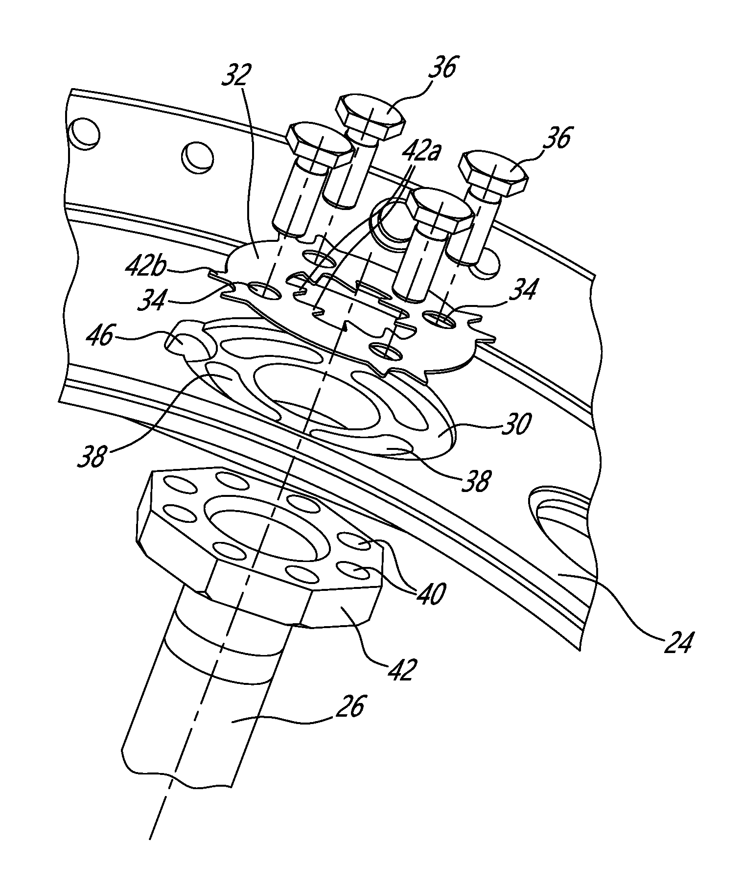
FIG. 6 is an exploded isometric view illustrating the bolted connection between one of the spokes and the outer structural ring; and
FIG. 7 is an isometric view illustrating the anti-rotation features of the bolted connection shown in FIG. 6.
DETAILED DESCRIPTION
FIG. 1 illustrates a turbofan gas turbine engine 10 of a type preferably provided for use in subsonic flight, generally comprising in serial flow communication a fan 12 through which ambient air is propelled, a multistage compressor 14 for pressurizing the air, a combustor 16 in which the compressed air is mixed with fuel and ignited for generating an annular stream of hot combustion gases, and a turbine section 18 for extracting energy from the combustion gases.
FIG. 2 shows a portion of the turbine section 18. More particularly, FIG. 2 illustrates a mid-turbine frame module 20 adapted to be axially mounted between first and second turbine sections. The mid-turbine frame module 20 comprises an inner structural ring 22 adapted to receive and support a bearing casing 23 (see FIG. 5) which is, in turn, adapted to support the main shafts of the engine 10. As shown in FIG. 5, the bearing casing 23 may be detachably mounted to the inner ring by means of bolts 25. Now referring concurrently to FIGS. 2 and 3, it can be seen that the inner structural ring 22 is structurally supported by an outer structural ring 24 by means of a plurality of circumferentially distributed spokes 26 (6 in the illustrated embodiment). In addition of transferring the loads from the inner ring 22 to the outer ring 24, the spokes 26 are used to centralize the inner ring 22 and, thus, the bearing casing 23 relative to the outer ring 24.
Each spoke 26 may extend radially through a hollow strut 27 (FIG. 5) of a non-structural integrated strut-vane casing 28 (FIG. 2) "floatingly" mounted between the inner and outer structural rings 22 and 24 for guiding the combustion gases between two axially adjacent turbine stages. The casing 28 has radially outer and radially inner gaspath walls 28a, 28b (FIG. 5) defining therebetween a portion of the gaspath of the turbine section 18. According to the illustrated embodiment, the casing 28 does not play a structural role. That is loads from the bearing casing 23 are not transmitted to the outer casing 24 via the integrated strut-vane casing 28. The loads are rather transmitted through the spokes 26, which are shielded from the hot combustion gases by the hollow struts 27 of the integrated strut-vane casing 28. In such an arrangement, the spokes can be referred to as cold spokes.
As best shown in FIGS. 3 to 5, each spoke 26 is threadably engaged at its radially inner end with a threaded boss 30 integrally formed on the inner ring 22. According to the illustrated example, external threads at the radially inner end of the spokes are engaged with mating threads of an internally threaded boss 30 projecting radially outwardly from the radially outer surface of the inner ring 22. It is noted that the threaded bosses 30 could extend from the radially inner circumferential surface of the inner ring 22 and are, thus, not limited to be provided on the radially outer surface of the inner ring. The bosses could be provided at various radial/circumferential locations on the inner ring. Also, it is understood that the internal threads could be provided on the spokes and the external threads on the bosses. Also each threaded site on the inner ring 22 could adopt various suitable configurations to provide the required length of threads.
The threads on the spoke 26 may be machined concurrently with a turning operation of the spoke. The inner ring 22 may be casted, machined or otherwise suitably produced in the form of a simple ring having circumferentially spaced-apart threaded bosses on one of its radially outer or inner surface.
The above described arrangement provides for a simple and efficient way of adjustably attaching the spoke 26 to the inner ring 22 supporting the bearing casing 23. No additional fasteners or attachment parts are required. It provides for a compact design allowing for improved aerodynamic gaspath (additional radial space available to modify the inner and outer gaspath walls 28a, 28b). The threaded connection between the spoke inner end and the inner ring 22 reduces the accumulation of misalignment and simplify the bearing casing centralization procedure as compared to conventional spoke mounting arrangement with pads, bolts and shim spacers.
As best shown in FIGS. 6 and 7, each spoke 26 may be bolted at its radially outer end to the outer structural ring 24. At each point of assembly, a seat 31 is defined in the radially outer surface of the outer ring 24 for receiving a washer 32. The washer 32 may have a flat body with circumferentially spaced-apart holes 34 define therein for individually receiving respective bolts 36 or equivalent threaded fasteners (4 in the illustrated example). Corresponding elongated mounting slots 38 are defined in the bottom of the seat 31 for receiving the bolts 36. Each slot 38 permits alignment with at least one corresponding threaded hole 40 of an annular array of holes defined in a mounting flange or head 42 at the radially outer end of the spoke 26. Accordingly, the washer 32 is positioned in its associated seat 31 so that the holes 34 defined therein are in alignment or registry with the corresponding holes 40 of the mounting flange of the spoke 26. After the holes 34 in the washer 32 have been appropriately angularly aligned with the corresponding holes 40 in the mounting flange of the spoke 26, the bolts 36 are tighten to firmly join the spoke 26 to the radially inner circumferential surface of the outer structural ring 24.
As shown in FIGS. 6 and 7, the washer 32 may be provided at each hole 34 with a pair of anti-rotation tabs 42. According to the illustrated embodiment, each pair of anti-rotation tab 42 comprises a first tab 42a on the inner diameter of the washer 32 and an opposed facing second tab 42b on the outer diameter of the washer 32. As shown in FIG. 7, each pair of first and second tabs 42a, 42b may be bent out of the plane of the washer 32 into engagement with the head of the associated bolt 36 to positively lock the same against rotation. In the illustrated embodiment, each pair of anti-rotation tabs 42 is engageable with opposed sides of a hexagonal head of the associated bolt 36. This effectively prevents loosening of the bolts 36. While deformable or bendable tabs have been shown, it is understood that any suitable types of locking tabs could be used as well.
Referring to FIG. 6, it can be seen that a peripheral portion of the washer may be deformed into an anti-rotation notch or catch 46 provided at one location around the perimeter of the washer seat 30. According to one embodiment, the peripheral portion of the washer 32 could be punched into the anti-rotation catch 46 after all the bolts 36 have been tighten and locked in position with the tabs 42. This prevents rotational movement of the washer 32 relative to the outer casing 24, thereby locking the spoke 26 against rotation about its longitudinal axis.
During the assembly of the mid-turbine frame, the threaded engagement of the spokes 26 in the threaded bosses 30 is adjusted by rotating the spokes 26 about their respective axes in the clockwise or counter-clockwise direction depending on the thread direction so that the radially outer end of the spoke 26 firmly abuts the radially inner circumferential surface of the outer ring 24. Each spoke is so rotated in order to adjust the length of the portion of the spoke projecting radially outwardly from the inner ring 22. The spokes are unthreaded until the radially outer end of all spokes uniformly abuts the inner surface of the outer ring. The length of the spokes is adjusted so that each spoke exerts a radially outwardly directed force against the inner surface of the outer ring. The forces shall be uniform all around the ring. Once all the spokes have been appropriately adjusted to collectively center the inner ring with respect to the outer ring, then, the bolts 36 are threadably engaged from outside of the outer ring with corresponding threaded holes defined in the head of the spoke at the radially outer end thereof.
The skilled reader will appreciate that the spokes 26 are mounted in compression between the radially inner and outer rings 22, 24. That is the load carrying spokes 36 are pre-stressed in compression during engine assembly as described hereinabove. Accordingly, a compression action is always maintained on the threads at the radially inner and outer ends of the spokes 26. This helps preventing loosening of the threaded connections at both ends of the spokes. During engine operation, when the spokes 26 are exposed to heat, the spokes tend to expand, thereby further increasing the pressure on the threads and, thus, preventing loosening. The advantage to building the spokes pre-stressed in compression is 2 fold: 1) the amount of assembly pre-stress is minimized, thereby facilitating assembly and, as the spokes thermally expand during engine operation, they will react against the inner and outer rings, thereby increasing the compressive loads in the spokes. If the spoke were to be assembled in tension, the level of pre-stress tension would be thermally reduced during engine operation, and, thus, the threaded connection subject to loosening. This could give rise to bearing de-centralization issues. As can be appreciated from the foregoing, these problems may be overcome by assembling the spokes in compression. Engine operation will only add to the amount of compression, thereby further preventing loosening of the threaded connections.
The above description is meant to be exemplary only, and one skilled in the art will recognize that changes may be made to the embodiments described without departing from the scope of the invention disclosed. Any modifications which fall within the scope of the present invention will be apparent to those skilled in the art, in light of a review of this disclosure, and such modifications are intended to fall within the appended claims.
* * * * *
D00000
D00001
D00002
D00003
D00004
XML
uspto.report is an independent third-party trademark research tool that is not affiliated, endorsed, or sponsored by the United States Patent and Trademark Office (USPTO) or any other governmental organization. The information provided by uspto.report is based on publicly available data at the time of writing and is intended for informational purposes only.
While we strive to provide accurate and up-to-date information, we do not guarantee the accuracy, completeness, reliability, or suitability of the information displayed on this site. The use of this site is at your own risk. Any reliance you place on such information is therefore strictly at your own risk.
All official trademark data, including owner information, should be verified by visiting the official USPTO website at www.uspto.gov. This site is not intended to replace professional legal advice and should not be used as a substitute for consulting with a legal professional who is knowledgeable about trademark law.