High toughness and high tensile strength thick steel plate and production method therefor
Kitsuya , et al. Oc
U.S. patent number 10,443,110 [Application Number 15/126,838] was granted by the patent office on 2019-10-15 for high toughness and high tensile strength thick steel plate and production method therefor. This patent grant is currently assigned to JFE Steel Corporation. The grantee listed for this patent is JFE STEEL CORPORATION. Invention is credited to Shigeru Endo, Kazukuni Hase, Kenji Hayashi, Masayuki Horie, Katsuyuki Ichimiya, Teruhisa Kinugawa, Shigeki Kitsuya, Naoki Matsunaga, Yusuke Terazawa.

| United States Patent | 10,443,110 |
| Kitsuya , et al. | October 15, 2019 |
High toughness and high tensile strength thick steel plate and production method therefor
Abstract
A high toughness and high tensile strength thick steel plate has a plate thickness of 100 mm or more, wherein a reduction of area in a center of the plate thickness by tension in a plate thickness direction is 40% or more. Thus, a high tensile strength thick steel plate with excellent strength and toughness in a center of the plate thickness can be obtained with no need for a larger production line, even in the case of producing a high strength thick steel plate for which the addition amount of alloying element needs to be increased.
| Inventors: | Kitsuya; Shigeki (Tokyo, JP), Ichimiya; Katsuyuki (Tokyo, JP), Hase; Kazukuni (Tokyo, JP), Kinugawa; Teruhisa (Tokyo, JP), Matsunaga; Naoki (Tokyo, JP), Hayashi; Kenji (Tokyo, JP), Horie; Masayuki (Tokyo, JP), Terazawa; Yusuke (Tokyo, JP), Endo; Shigeru (Tokyo, JP) | ||||||||||
|---|---|---|---|---|---|---|---|---|---|---|---|
| Applicant: |
|
||||||||||
| Assignee: | JFE Steel Corporation (Tokyo,
JP) |
||||||||||
| Family ID: | 54143872 | ||||||||||
| Appl. No.: | 15/126,838 | ||||||||||
| Filed: | September 9, 2014 | ||||||||||
| PCT Filed: | September 09, 2014 | ||||||||||
| PCT No.: | PCT/JP2014/004631 | ||||||||||
| 371(c)(1),(2),(4) Date: | September 16, 2016 | ||||||||||
| PCT Pub. No.: | WO2015/140846 | ||||||||||
| PCT Pub. Date: | September 24, 2015 |
Prior Publication Data
| Document Identifier | Publication Date | |
|---|---|---|
| US 20170088913 A1 | Mar 30, 2017 | |
Foreign Application Priority Data
| Mar 20, 2014 [JP] | 2014-058611 | |||
| Current U.S. Class: | 1/1 |
| Current CPC Class: | C22C 38/001 (20130101); C22C 38/002 (20130101); C22C 38/58 (20130101); C22C 38/005 (20130101); C21D 8/0205 (20130101); C21D 8/0226 (20130101); C21D 9/0081 (20130101); C22C 38/32 (20130101); C22C 38/42 (20130101); C21D 8/005 (20130101); C21D 1/18 (20130101); B21J 5/02 (20130101); B22D 11/001 (20130101); C22C 38/16 (20130101); C22C 38/14 (20130101); C22C 38/08 (20130101); C22C 38/04 (20130101); C21D 9/46 (20130101); C22C 38/44 (20130101); C22C 38/18 (20130101); C22C 38/02 (20130101); C22C 38/12 (20130101); C21D 7/13 (20130101); C22C 38/06 (20130101); C22C 38/46 (20130101); C22C 38/50 (20130101); C21D 8/0263 (20130101); C22C 38/54 (20130101); C22C 38/48 (20130101) |
| Current International Class: | C21D 9/46 (20060101); C22C 38/58 (20060101); C22C 38/08 (20060101); C22C 38/12 (20060101); C22C 38/14 (20060101); C22C 38/16 (20060101); C22C 38/18 (20060101); C22C 38/46 (20060101); C21D 9/00 (20060101); C21D 8/00 (20060101); C21D 7/13 (20060101); C22C 38/32 (20060101); C22C 38/54 (20060101); C22C 38/50 (20060101); C22C 38/48 (20060101); C22C 38/44 (20060101); C22C 38/42 (20060101); C22C 38/06 (20060101); C22C 38/04 (20060101); C22C 38/02 (20060101); C22C 38/00 (20060101); C21D 8/02 (20060101); C21D 1/18 (20060101); B22D 11/00 (20060101); B21J 5/02 (20060101) |
References Cited [Referenced By]
U.S. Patent Documents
| 9945015 | April 2018 | Yuga et al. |
| 10000833 | June 2018 | Kitsuya et al. |
| 2014/0246131 | September 2014 | Yuga et al. |
| 2014/0346121 | November 2014 | Poeschl et al. |
| 2015/0203945 | July 2015 | Ichimiya |
| 2016/0010192 | January 2016 | Kitsuya et al. |
| 2017/0088913 | March 2017 | Kitsuya et al. |
| 101341269 | Jan 2009 | CN | |||
| 101962741 | Feb 2011 | CN | |||
| 102176985 | Sep 2011 | CN | |||
| 102605280 | Jul 2012 | CN | |||
| 102712972 | Oct 2012 | CN | |||
| 103710640 | Apr 2014 | CN | |||
| 55114404 | Sep 1980 | JP | |||
| S5831069 | Feb 1983 | JP | |||
| 6127320 | Feb 1986 | JP | |||
| H01219121 | Sep 1989 | JP | |||
| 02197383 | Aug 1990 | JP | |||
| 04190902 | Jul 1992 | JP | |||
| 06198394 | Jul 1994 | JP | |||
| 1088231 | Apr 1998 | JP | |||
| 2913426 | Jun 1999 | JP | |||
| 2000263103 | Sep 2000 | JP | |||
| 2002194431 | Jul 2002 | JP | |||
| 2002210502 | Jul 2002 | JP | |||
| 2002256380 | Sep 2002 | JP | |||
| 3333619 | Oct 2002 | JP | |||
| 2005068519 | Mar 2005 | JP | |||
| 2006111918 | Apr 2006 | JP | |||
| 2008308736 | Dec 2008 | JP | |||
| 2009235524 | Oct 2009 | JP | |||
| 2010106298 | May 2010 | JP | |||
| 2010280976 | Dec 2010 | JP | |||
| 2011202214 | Oct 2011 | JP | |||
| 2013095927 | May 2013 | JP | |||
| 5354164 | Nov 2013 | JP | |||
| 5477457 | Apr 2014 | JP | |||
| 2014038200 | Aug 2016 | JP | |||
| 2013051231 | Apr 2013 | WO | |||
| 2013091845 | Jun 2013 | WO | |||
| 2014141697 | Sep 2014 | WO | |||
| 2015140846 | Sep 2015 | WO | |||
Other References
|
US translation of JP 2008 308736 (Year: 2008). cited by examiner . Supplementary European Search Report for Application No. 14886339.2, dated Feb. 15, 2017, 7 pages. cited by applicant . Japanese Office Action with partial English language translation for Application No. 2016-508308, dated Dec. 20, 2016, 3 pages. cited by applicant . Chinese Office Action for Chinese Application No. 201480077199.6, dated Oct. 23, 2017 with Concise Statement of Relevance, 10 pages. cited by applicant . Korean Office Action for Korean Application No. 10-2016-7025832, dated Aug. 10, 2017, including Concise Statement of Relevance of Office Action, 8 pages. cited by applicant . International Search Report and Written Opinion for International Application No. PCT/JP2014/004631, dated Jan. 6, 2015, 5 pages. cited by applicant . Iron and Steel, 66 (1980), pp. 201-210. cited by applicant . Chinese Office Action for Chinese Application No. 201480077199.6, dated Apr. 26, 2017 with search report and concise statement of relevance, 10 pages. cited by applicant . Non Final Office Action for U.S. Appl. No. 15/304,702, dated Nov. 14, 2018, 25 pages. cited by applicant. |
Primary Examiner: Washville; Jeffrey D
Attorney, Agent or Firm: RatnerPrestia
Claims
The invention claimed is:
1. A high toughness and high tensile strength thick steel plate having a plate thickness of 100 mm or more, and having a yield strength of 620 MPa or more, and a toughness (.sub.VE.sub.-40) of 70 J or more, and wherein a reduction of area value of the steel plate is 40% or more, measured with a tensile test piece obtained from a center position of the plate along a thickness direction of the plate.
2. The high toughness and high tensile strength thick steel plate according to claim 1, comprising, in mass %: 0.08% to 0.20% of C; 0.40% or less of Si; 0.5% to 5.0% of Mn; 0.015% or less of P; 0.0050% or less of S; 3.0% or less of Cr; 5.0% or less of Ni; 0.005% to 0.020% of Ti; 0.080% or less of Al; 0.0070% or less of N; and 0.0030% or less of B, with a balance being Fe and incidental impurities, wherein a relationship in Formula (1) is satisfied: Ceq.sup.IIW=C+Mn/6+(Cu+Ni)/15+(Cr+Mo+V)/5.gtoreq.0.57 (1), where each element symbol in Formula (1) Indicates a content in steel in mass %, and the content of any element not contained in the steel is 0.
3. The high toughness and high tensile strength thick steel plate according to claim 2, further comprising, in mass %, one or more selected from: 0.50% or less of Cu; 1.50% or less of Mo; 0.200% or less of V; 0.100% or less of Nb; 0.0005% to 0.0100% of Mg; 0.01% to 0.20% of Ta; 0.005% to 0.1% of Zr; 0.001% to 0.01% of Y; 0.0005% to 0.0050% of Ca; and 0.0005% to 0.0200% of REM.
4. A production method for a high toughness and high tensile strength thick steel plate having a plate thickness of 100 mm or more and having a yield strength of 620 MPa or more, and a toughness (.sub.VE.sub.-40) of 70 J or more, comprising: heating a continuously-cast slab of steel to 1200.degree. C. to 1350.degree. C.; hot forging the steel at 1000.degree. C. or more with a strain rate of 3/s or less and a cumulative rolling reduction of 15% or more, using dies such that, when a length of a shorter short side of respective short sides of the dies facing each other is 1, a length of a short side of an other one of the dies facing the shorter short side is 1.1 to 3.0; hot rolling the steel; and quenching and tempering the steel, wherein a reduction of area value of the steel plate is 40% or more, measured with a tensile test niece obtained from a center position of the plate along a thickness direction of the plate.
5. A production method for the high toughness and high tensile strength thick steel plate according to claim 4, further comprising: allowing the steel to cool after hot forging; reheating the steel to an Ac.sub.3 point to 1250.degree. C.; hot rolling the steel by performing two or more passes with a per-pass rolling reduction of 4% or more; allowing the steel to cool; reheating the steel to the Ac.sub.3 point to 1050.degree. C.; quenching the steel to an Ar.sub.3 point to 350.degree. C.; and tempering the steel in a range of 450.degree. C. to 700.degree. C.
6. The production method for the high toughness and high tensile strength thick steel plate according to claim 4, wherein a rolling reduction ratio in the high toughness and high tensile strength thick steel plate from a raw material before working is 3 or less.
7. The production method for the high toughness and high tensile strength thick steel plate according to claim 4, wherein in the hot forging, forging with a per-pass rolling reduction of 5% or more is applied one or more times, or wherein in the hot forging, forging with a per-pass rolling reduction of 7% or more is applied one or more times.
8. The production method for the high toughness and high tensile strength thick steel plate according to claim 4, wherein in the hot forging, at least one pass has a cumulative elapsed time of 3 s or more under a load that is not less than a maximum load of the pass.times.0.9 and not more than the maximum load of the pass.
9. The production method for the high toughness and high tensile strength thick steel plate according to claim 4, comprising, in mass %: 0.08% to 0.20% of C; 0.40% or less of Si; 0.5% to 5.0% of Mn; 0.015% or less of P; 0.0050% or less of S; 3.0% or less of Cr; 5.0% or less of Ni; 0.005% to 0.020% of Ti; 0.080% or less of Al; 0.0070% or less of N; and 0.0030% or less of B, with a balance being Fe and incidental impurities, wherein a relationship in Formula (1) is satisfied: Ceq.sup.IIW=C+Mn/6+(Cu+Ni)/15+(Cr+Mo+V)/5.gtoreq.0.57 (1), where each element symbol in Formula (1) indicates a content in steel in mass %, and the content of any element not contained in the steel is 0.
10. The production method for the high toughness and high tensile strength thick steel plate according to claim 4, further comprising, in mass %, one or more selected from: 0.50% or less of Cu; 1.50% or less of Mo; 0.200% or less of V; 0.100% or less of Nb; 0.0005% to 0.0100% of Mg; 0.01% to 0.20% of Ta; 0.005% to 0.1% of Zr; 0.001% to 0.01% of Y; 0.0005% to 0.0050% of Ca; and 0.0005% to 0.0200% of REM.
11. The production method for the high toughness and high tensile strength thick steel plate according to claim 5, wherein a rolling reduction ratio in the high toughness and high tensile strength thick steel plate from a raw material before working is 3 or less.
12. The production method for the high toughness and high tensile strength thick steel plate according to claim 5, wherein in the hot forging, forging with a per-pass rolling reduction of 5% or more is applied one or more times, or wherein in the hot forging, forging with a per-pass rolling reduction of 7% or more is applied one or more times.
13. The production method for the high toughness and high tensile strength thick steel plate according to claim 6, wherein in the hot forging, forging with a per-pass rolling reduction of 5% or more is applied one or more times, or wherein in the hot forging, forging with a per-pass rolling reduction of 7% or more is applied one or more times.
14. The production method for the high toughness and high tensile strength thick steel plate according to claim 5, wherein in the hot forging, at least one pass has a cumulative elapsed time of 3 s or more under a load that is not less than a maximum load of the pass.times.0.9 and not more than the maximum load of the pass.
15. The production method for the high toughness and high tensile strength thick steel plate according to claim 6, wherein in the hot forging, at least one pass has a cumulative elapsed time of 3 s or more under a load that is not less than a maximum load of the pass.times.0.9 and not more than the maximum load of the pass.
16. The production method for the high toughness and high tensile strength thick steel plate according to claim 7, wherein in the hot forging, at least one pass has a cumulative elapsed time of 3 s or more under a load that is not less than a maximum load of the pass.times.0.9 and not more than the maximum load of the pass.
Description
CROSS REFERENCE TO RELATED APPLICATIONS
This is the U.S. National Phase application of PCT/JP2014/004631, filed Sep. 9, 2014, which claims priority to Japanese Patent Application No. 2014-058611, filed Mar. 20, 2014, the disclosures of each of these applications being incorporated herein by reference in their entireties for all purposes.
TECHNICAL FIELD
The disclosure relates to a thick steel plate having excellent strength, toughness, and weldability and used in steel structures such as buildings, bridges, ships, offshore structures, construction machinery, tanks, and penstocks, and a production method therefor. The disclosure particularly provides a high toughness and high tensile strength thick steel plate whose plate thickness is 100 mm or more and reduction of area in a center of the plate thickness by tension in the plate thickness direction is 40% or more, and a production method therefor.
BACKGROUND
In the case of using a steel material in the fields such as buildings, bridges, ships, offshore structures, construction machinery, tanks, and penstocks, the steel material is made into a desired shape by welding according to the shape of the steel structure. Steel structures are becoming increasingly larger in size in recent years, and the use of stronger and thicker steel materials is growing markedly.
A thick steel plate having a plate thickness of 100 mm or more is typically produced by blooming a large steel ingot produced by ingot casting and then hot rolling the obtained slab. In this ingot casting and blooming process, however, a concentrated segregation area of a hot top portion or a negative segregation area of a steel ingot bottom portion needs to be discarded. This hinders yield improvement, and causes higher manufacturing cost and longer construction time.
On the other hand, in the case of producing a thick steel plate having a plate thickness of 100 mm or more by a process that uses a continuously-cast slab as a raw material, the aforementioned concern does not exist, but the working reduction to the product thickness is low because the thickness of the continuously-cast slab is smaller than the slab produced by ingot casting. Moreover, the general tendency to require stronger and thicker steel materials in recent years has increased the amount of alloying element added to ensure necessary properties. This causes new problems such as center porosity deriving from center segregation and inner quality degradation due to upsizing.
To solve these problems, the following techniques have been proposed to, in a process of producing an ultra-thick steel plate from a continuously-cast slab, compress center porosity to improve the properties of the center segregation area in the steel plate.
For example, Non Patent Literature (NPL) 1 describes the technique of compressing center porosity by increasing the rolling shape ratio during hot rolling of a continuously-cast slab.
Patent Literatures (PTLs) 1 and 2 describe the techniques of compressing center porosity in a continuously-cast slab by, when producing the continuously-cast slab, working the material using rolls or flat dies in a continuous casting machine.
PTL 3 describes the technique of compressing center porosity by performing forging before hot rolling when producing a thick steel plate with a cumulative working reduction of 70% or less from a continuously-cast slab.
PTL 4 describes the technique of not only eliminating center porosity but also reducing the center segregation zone to improve the resistance to temper embrittlement by, when producing an ultra-thick steel plate from a continuously-cast slab through forging and thick plate rolling with a total working reduction of 35% to 67%, holding the center of the plate thickness of the raw material at a temperature of 1200.degree. C. or more for 20 hours or more before forging and setting the working reduction of the forging to 16% or more.
PTL 5 describes the technique of remedying center porosity and center segregation by cross-forging a continuously-cast slab and then hot rolling the slab.
PTL 6 describes the technique relating to the method of producing a thick steel plate having a tensile strength of 588 MPa or more with center porosity being eliminated and the center segregation zone being reduced, by holding a continuously-cast slab at a temperature of 1200.degree. C. or more for 20 hours or more, setting the working reduction of the forging to 17% or more, performing thick plate rolling so that the total working reduction including the forging is in the range of 23% to 50%, and applying quenching twice after the thick plate rolling.
PTL 7 describes the technique relating to the method of producing a thick steel plate excellent in weldability and ductility in the plate thickness direction by reheating a continuously-cast slab having a specific composition to 1100.degree. C. to 1350.degree. C., with a cumulative working reduction of 15% or more and a strain rate of 0.05/s to 3/s at 1000.degree. C. or more.
CITATION LIST
Patent Literatures
PTL 1: JP S55-114404 A PTL 2: JP S61-27320 A PTL 3: JP 3333619 B2 PTL 4: JP 2002-194431 A PTL 5: JP 2000-263103 A PTL 6: JP 2006-111918 A PTL 7: JP 2010-106298 A
Non-Patent Literatures
NPL 1: Iron and Steel, 66 (1980), pp. 201-210
SUMMARY
Technical Problem
However, the technique described in NPL 1 needs repeated rolling with a high rolling shape ratio, to obtain a steel plate having good inner quality. This exceeds the upper limit of the equipment specifications of the mill, and poses a production problem. If a typical method is used for rolling, the center of the plate thickness cannot be worked sufficiently, as a result of which center porosity may remain and degrade inner quality.
The techniques described in PTLs 1 and 2 need a larger continuous casting line to produce a thick steel plate of 100 mm or more in plate thickness. This requires a heavy investment in equipment.
The techniques described in PTLs 3 to 7 are effective in center porosity reduction and center segregation zone improvement. However, in the case where the techniques are applied to the production of a thick steel plate with a large addition amount of alloy and a yield strength of 620 MPa or more, defect sensitivity increases due to the strengthening of the material, and so the elongation and toughness of the center of the plate thickness are both insufficient.
It could therefore be helpful to provide a high tensile strength thick steel plate having excellent strength and toughness in a center of the plate thickness with no need for a larger continuous casting line or mill even in the case of producing a high strength thick steel plate for which the addition amount of alloying element needs to be increased, and a production method therefor. The high tensile strength thick steel plate has a plate thickness of 100 mm or more.
Solution to Problem
For thick steel plates of 100 mm or more in plate thickness in particular, we studied the control factors of the microstructure inside the steel plate with regard to the strength, toughness, and elongation of the center of the plate thickness, and made the following discoveries.
(A) To obtain good strength and toughness in the center of the plate thickness that has a significantly lower cooling rate than the steel plate surface, it is important to appropriately select the steel composition so that the microstructure is a martensite and/or bainite structure even with a lower cooling rate.
(B) To ensure good ductility in the center of the plate thickness of the thick steel plate that tends to have lower ductility due to strengthening and have higher defect sensitivity with respect to ductility, it is important to manage the die shape and total working reduction in hot forging and the strain rate, per-pass working reduction, and working time in the forging to compress center porosity and render it harmless.
The disclosure is based on the aforementioned discoveries and further studies. We thus provide the following.
1. A high toughness and high tensile strength thick steel plate having a plate thickness of 100 mm or more, wherein a reduction of area in a center of the plate thickness by tension in a plate thickness direction is 40% or more.
2. The high toughness and high tensile strength thick steel plate according to the foregoing 1, comprising (consisting of), in mass %: 0.08% to 0.20% of C; 0.40% or less of Si; 0.5% to 5.0% of Mn; 0.015% or less of P; 0.0050% or less of S; 3.0% or less of Cr; 5.0% or less of Ni; 0.005% to 0.020% of Ti; 0.080% or less of Al; 0.0070% or less of N; and 0.0030% or less of B, with a balance being Fe and incidental impurities, wherein a relationship in Formula (1) is satisfied: Ceq.sup.IIW=C+Mn/6+(Cu+Ni)/15+(Cr+Mo+V)/5.gtoreq.0.57 (1),
where each element symbol in Formula (1) indicates a content in steel in mass %, and the content of any element not contained in the steel is 0.
3. The high toughness and high tensile strength thick steel plate according to the foregoing 2, further comprising, in mass %, one or more selected from: 0.50% or less of Cu; 1.50% or less of Mo; 0.200% or less of V; and 0.100% or less of Nb.
4. The high toughness and high tensile strength thick steel plate according to the foregoing 2 or 3, further comprising, in mass %, one or more selected from: 0.0005% to 0.0100% of Mg; 0.01% to 0.20% of Ta; 0.005% to 0.1% of Zr; 0.001% to 0.01% of Y; 0.0005% to 0.0050% of Ca; and 0.0005% to 0.0200% of REM.
5. The high toughness and high tensile strength thick steel plate according to any one of the foregoing 1 to 4, having a yield strength of 620 MPa or more, and toughness (.sub.VE.sub.-40) of 70 J or more.
6. A production method for the high toughness and high tensile strength thick steel plate according to any one of the foregoing 1 to 5, comprising: heating a continuously-cast slab of steel to 1200.degree. C. to 1350.degree. C.; hot forging the steel at 1000.degree. C. or more with a strain rate of 3/s or less and a cumulative working reduction of 15% or more, using dies such that, when a length of a shorter short side of respective short sides of the dies facing each other is 1, a length of a short side of an other one of the dies facing the shorter short side is 1.1 to 3.0; hot rolling the steel; and quenching and tempering the steel.
7. A production method for the high toughness and high tensile strength thick steel plate according to any one of the foregoing 1 to 5, comprising: heating a continuously-cast slab of steel to 1200.degree. C. to 1350.degree. C.; hot forging the steel at 1000.degree. C. or more with a strain rate of 3/s or less and a cumulative working reduction of 15% or more, using dies such that, when a length of a shorter short side of respective short sides of the dies facing each other is 1, a length of a short side of an other one of the dies facing the shorter short side is 1.1 to 3.0; allowing the steel to cool; reheating the steel to an Ac.sub.3 point to 1250.degree. C.; hot rolling the steel by performing two or more passes with a per-pass working reduction of 4% or more; allowing the steel to cool; reheating the steel to the Ac.sub.3 point to 1050.degree. C.; quenching the steel to an Ar.sub.3 point to 350.degree. C.; and tempering the steel in a range of 450.degree. C. to 700.degree. C.
8. The production method for the high toughness and high tensile strength thick steel plate according to the foregoing 6 or 7, wherein a working reduction ratio in the high toughness and high tensile strength thick steel plate from a raw material before working is 3 or less.
9. The production method for the high toughness and high tensile strength thick steel plate according to any one of the foregoing 6 to 8, wherein in the hot forging, forging with a per-pass working reduction of 5% or more is applied one or more times.
10. The production method for the high toughness and high tensile strength thick steel plate according to any one of the foregoing 6 to 8, wherein in the hot forging, forging with a per-pass working reduction of 7% or more is applied one or more times.
11. The production method for the high toughness and high tensile strength thick steel plate according to any one of the foregoing 6 to 10, wherein in the hot forging, at least one pass has a cumulative elapsed time of 3 s or more under a load that is not less than a maximum load of the pass.times.0.9 and not more than the maximum load of the pass.
Advantageous Effect
With the disclosed techniques, it is possible to obtain a thick steel plate having a plate thickness of 100 mm or more with excellent yield strength and toughness of a base metal. The disclosed techniques significantly contribute to larger sizes of steel structures, improved safety of steel structures, improved yields, and shorter construction time, and so are industrially very useful. In particular, the disclosed techniques have the advantageous effect of obtaining good properties without upsizing a continuous casting line, etc. even in the case where the working reduction ratio from the raw material before working is 3 or less, while sufficient properties of the center of the plate thickness were conventionally hard to be obtained in such a case.
BRIEF DESCRIPTION OF THE DRAWINGS
In the accompanying drawings:
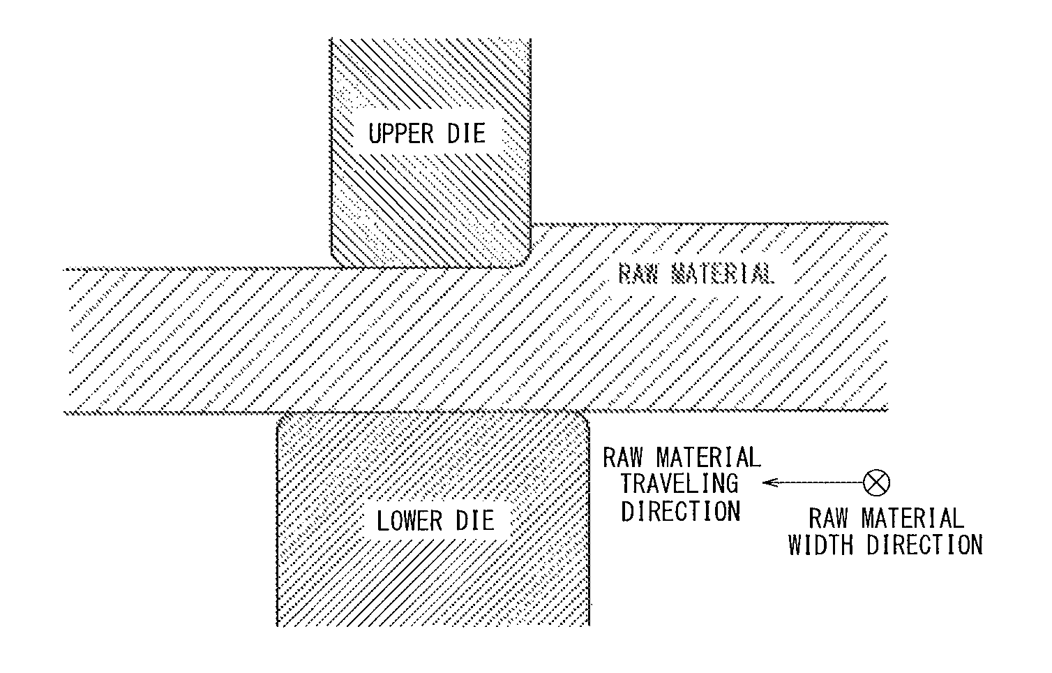
FIG. 1 is a diagram illustrating the short sides of dies facing each other; and
FIG. 2 is a diagram illustrating the result of calculating equivalent plastic strain in a raw material (steel plate).
DETAILED DESCRIPTION
Detailed description is given below.
The disclosure provides a forged material whose plate thickness is 100 mm or more and reduction of area in a center of the plate thickness by tension in the plate thickness direction is 40% or more. With such a structure, center porosity in the steel can be compressed to a size of 100 .mu.m or less and rendered substantially harmless.
The high tensile strength thick steel plate also has a yield strength of 620 MPa or more. This contributes to larger sizes of steel structures and improved safety of steel structures. The aforementioned properties can be obtained even in the case where the working reduction ratio from the raw material before working is 3 or less, while conventionally these properties were hard to be obtained in such a case.
The following describes the suitable ranges of the steel plate composition according to the disclosure. The % representation of the content of each element in the steel plate composition is mass %.
C: 0.08% to 0.20%
C is an element useful in obtaining the strength required of structural steel at low cost. To achieve the effect, the C content is preferably 0.08% or more. If the C content exceeds 0.20%, the toughness of the base metal and heat-affected zone degrades significantly. The upper limit is therefore preferably 0.20%. The C content is more preferably 0.08% to 0.14%.
Si: 0.40% or Less
Si is added for deoxidation. If the Si content exceeds 0.40%, the toughness of the base metal and heat-affected zone degrades significantly. The Si content is therefore preferably 0.40% or less. The Si content is more preferably in the range of 0.05% to 0.30%, and further preferably in the range of 0.1% to 0.30%.
Mn: 0.5% to 5.0%
Mn is added to ensure the strength of the base metal. If the Mn content is less than 0.5%, the effect is not sufficient. If the Mn content exceeds 5.0%, not only the toughness of the base metal degrades but also center segregation is facilitated to cause larger porosity of the slab. The upper limit is therefore preferably 5.0%. The Mn content is more preferably in the range of 0.6% to 2.0%, and further preferably in the range of 0.6% to 1.6%.
P: 0.015% or Less
If the P content exceeds 0.015%, the toughness of the base metal and heat-affected zone degrades significantly. The P content is therefore preferably 0.015% or less. The lower limit is not particularly limited, and may be 0%.
S: 0.0050% or Less
If the S content exceeds 0.0050%, the toughness of the base metal and heat-affected zone degrades significantly. The S content is therefore preferably 0.0050% or less. The lower limit is not particularly limited, and may be 0%.
Cr: 3.0% or Less
Cr is an element effective in strengthening the base metal. However, if the Cr content is high, weldability decreases. The Cr content is therefore preferably 3.0% or less. The Cr content is more preferably 0.1% to 2.0% in terms of production cost.
Ni: 5.0% or Less
Ni is an element effective in improving the strength of steel and the toughness of the heat-affected zone. However, if the Ni content exceeds 5.0%, economic efficiency drops significantly. The Ni content is therefore preferably 5.0% or less. The Ni content is more preferably 0.5% to 4.0%.
Ti: 0.005% to 0.020%
Ti generates TiN when heated, thus effectively suppressing coarsening of austenite grains and improving the toughness of the base metal and heat-affected zone. However, if the Ti content exceeds 0.020%, Ti nitride coarsens and degrades the toughness of the base metal. Hence, in the case of adding Ti, the Ti content is preferably in the range of 0.005% to 0.020%. The Ti content is more preferably in the range of 0.008% to 0.015%.
Al: 0.080% or Less
Al is added to sufficiently deoxidize molten steel. However, if the Al content exceeds 0.080%, the amount of Al dissolving in the base metal increases, which degrades the toughness of the base metal. The Al content is therefore preferably 0.080% or less. The Al content is more preferably in the range of 0.020% to 0.080%, and further preferably in the range of 0.020% to 0.060%.
N: 0.0070% or Less
N has the effect of, by forming a nitride with Ti or the like, refining the microstructure and improving the toughness of the base metal and heat-affected zone. However, if the N content exceeds 0.0070%, the amount of N dissolving in the base metal increases, which significantly degrades the toughness of the base metal. Moreover, a coarse carbonitride is formed in the heat-affected zone, and degrades the toughness. The N content is therefore preferably 0.0070% or less. The N content is more preferably 0.0050% or less, and further preferably 0.0040% or less.
B: 0.0030% or Less
B has the effect of, by being segregated in an austenite grain boundary, suppressing ferrite transformation from the grain boundary and enhancing quench hardenability. However, if the B content exceeds 0.0030%, B precipitates as a carbonitride and decreases quench hardenability, which causes lower toughness. The B content is therefore preferably 0.0030% or less. In the case of adding B, the B content is more preferably in the range of 0.0003% to 0.0030%, and further preferably in the range of 0.0005% to 0.0020%.
In addition to the aforementioned elements, the high tensile strength steel according to the disclosure may further contain one or more selected from Cu, Mo, V, and Nb to enhance strength and toughness.
Cu: 0.50% or Less
Cu can improve the strength of steel without degrading the toughness. However, if the Cu content exceeds 0.50%, the steel plate surface cracks during hot working. The Cu content is therefore 0.50% or less.
Mo: 1.50% or Less
Mo is an element effective in strengthening the base metal. However, if the Mo content exceeds 1.50%, the precipitation of a hard alloy carbide causes an increase in strength and degrades toughness. The upper limit is therefore preferably 1.50%. The Mo content is more preferably in the range of 0.02% to 0.80%.
V: 0.200% or Less
V has the effect of improving the strength and toughness of the base metal, and also is effective in reducing solute N by precipitating as VN. However, if the V content exceeds 0.200%, the precipitation of hard VC degrades the toughness of steel. Hence, in the case of adding V, the V content is preferably 0.200% or less. The V content is more preferably in the range of 0.010% to 0.100%.
Nb: 0.100% or Less
Nb is useful as it has the effect of improving the strength of the base metal. However, if the Nb content exceeds 0.100%, the toughness of the base metal degrades significantly. The upper limit is therefore 0.100%. The Nb content is preferably 0.025% or less.
In addition to the aforementioned components, the high tensile strength steel according to the disclosure may further contain one or more selected from Mg, Ta, Zr, Y, Ca, and REM to further improve the material quality.
Mg: 0.0005% to 0.0100%
Mg is an element that forms a stable oxide at high temperature, and effectively suppresses coarsening of austenite grains in the heat-affected zone and improves the toughness of the weld. To achieve the effect, a Mg content of 0.0005% or more is effective. If the Mg content exceeds 0.0100%, the amount of inclusion increases and the toughness decreases. Hence, in the case of adding Mg, the Mg content is preferably 0.0100% or less. The Mg content is more preferably in the range of 0.0005% to 0.0050%.
Ta: 0.01% to 0.20%
Ta is effective in improving strength, when added in an appropriate amount. If the Ta content is less than 0.01%, the effect is not obvious. If the Ta content exceeds 0.20%, a precipitate is generated and causes lower toughness. The Ta content is therefore preferably 0.01% to 0.20%.
Zr: 0.005% to 0.1%
Zr is an element effective in improving strength. If the Zr content is less than 0.005%, the effect is not obvious. If the Zr content exceeds 0.1%, a coarse precipitate is generated and causes lower toughness of steel. The Zr content is therefore 0.005% to 0.1%.
Y: 0.001% to 0.01%
Y is an element that forms a stable oxide at high temperature, and effectively suppresses coarsening of austenite grains in the heat-affected zone and improves the toughness of the weld. If the Y content is less than 0.001%, the effect cannot be achieved. If the Y content exceeds 0.01%, the amount of inclusion increases and the toughness decreases. The Y content is therefore 0.001% to 0.01%.
Ca: 0.0005% to 0.0050%
Ca is an element useful in morphological control of sulfide inclusion. To achieve the effect, the Ca content needs to be 0.0005% or more. If the Ca content exceeds 0.0050%, cleanliness decreases and toughness degrades. Hence, in the case of adding Ca, the Ca content is preferably 0.0050% or less. The Ca content is more preferably in the range of 0.0005% to 0.0025%.
REM: 0.0005% to 0.0200%
REM has the effect of forming an oxide and a sulfide in steel and improving the material quality, as with Ca. To achieve the effect, the REM content needs to be 0.0005% or more. If the REM content exceeds 0.0200%, the effect saturates. Hence, in the case of adding REM, the REM content is preferably 0.0200% or less. The REM content is more preferably in the range of 0.0005% to 0.0100%.
Ceq.sup.IIW (%).gtoreq.0.57
In the disclosure, appropriate components need to be added to ensure high strength and good toughness in the center of the plate thickness. It is important to add components so that Ceq.sup.IIW (%) defined in the following Formula (1) satisfies the relationship Ceq.sup.IIW.gtoreq.0.57: Ceq.sup.IIW=C+Mn/6+(Cu+Ni)/15+(Cr+Mo+V)/5.gtoreq.0.57 (1).
Each element symbol in the formula indicates the content of the corresponding element (mass %).
The following describes the production conditions according to the disclosure.
In the following description, the temperature ".degree. C." indicates the temperature in the center of the plate thickness. In particular, the disclosed method of producing a thick steel plate requires hot forging a steel raw material under the following conditions, in order to render casting defects such as center porosity in the steel raw material harmless.
Hot Working Conditions for Steel Raw Material
Heating Temperature: 1200.degree. C. to 1350.degree. C.
A steel raw material for a continuous-cast steel or slab having the aforementioned composition is subject to steelmaking and continuous casting by a typically known method such as a converter, an electric heating furnace, or a vacuum melting furnace, and then reheated to 1200.degree. C. to 1350.degree. C. If the reheating temperature is less than 1200.degree. C., a predetermined cumulative working reduction and temperature lower limit of hot working cannot be ensured, and also the deformation resistance during hot forging is high and a sufficient per-pass working reduction cannot be ensured. As a result, a larger number of passes are needed, which not only decreases production efficiency but also makes it impossible to compress casting defects such as center porosity in the steel raw material to render them harmless. The reheating temperature is therefore 1200.degree. C. or more. If the reheating temperature exceeds 1350.degree. C., an excessive amount of energy is consumed and surface defects tend to occur due to scale during heating, leading to an increased mending load after hot forging. The upper limit is therefore 1350.degree. C.
Forging Temperature of Hot Forging: 1000.degree. C. or More
If the forging temperature of hot forging is less than 1000.degree. C., the deformation resistance during hot forging increases and the load on the forging machine increases, making it impossible to reliably render center porosity harmless. The forging temperature is therefore 1000.degree. C. or more. The upper limit of the forging temperature is not particularly limited, but is preferably about 1350.degree. C. in terms of production cost.
Asymmetric Shapes of Facing Dies
Hot forging according to the disclosure is performed using a pair of facing dies whose long sides lie in the width direction of the continuously-cast slab and whose short sides lie in the traveling direction of the continuously-cast slab. Hot forging according to the disclosure has a feature that the respective short sides of the facing dies have different lengths, as illustrated in FIG. 1.
When the length of the shorter one (the short side of the upper die in FIG. 1) of the respective short sides of the facing dies is 1, the length of the short side (the short side of the lower die in FIG. 1) of the opposite die is 1.1 to 3.0 with respect to the shorter short side. In this way, the strain distribution can be made asymmetrical, and also the position of the minimum strain imparted during forging and the position of occurrence of center porosity in the continuously-cast slab can be kept from coinciding with each other. As a result, center porosity is rendered harmless more reliably.
If the ratio of the longer short side to the shorter short side is less than 1.1, the effect of rendering center porosity harmless is not sufficient. If the ratio of the longer short side to the shorter short side exceeds 3.0, the efficiency of hot forging drops significantly. It is therefore important to use, in hot forging according to the disclosure, such dies that, when the length of the shorter one of the respective short sides of the pair of dies facing each other is 1, the length of the short side facing the shorter short side is 1.1 to 3.0. Here, the die having the shorter short side may be above or below the continuously-cast slab, as long as the short side of the opposite die satisfies the aforementioned ratio. In other words, the short side of the lower die may be shorter in FIG. 1.
FIG. 2 illustrates the result of calculating equivalent plastic strain in the raw material (steel plate) in the plate thickness direction of the raw material, in the case where the short sides of the upper and lower dies have the same length (the conventional dies indicated by the white circles in the drawing) and in the case where the ratio of the longer short side to the shorter short side is 2.5 (the dies according to the disclosure indicated by the black circles in the drawing). The conditions of hot forging using the dies are the same except the shape of the dies, where the heating temperature is 1250.degree. C., the working start temperature is 1215.degree. C., the working end temperature is 1050.degree. C., the cumulative working reduction is 16%, the strain rate is 0.1/s, the maximum per-pass working reduction is 8%, and the raw material is not worked in the width direction.
As can be seen from FIG. 2, the hot forging using the dies according to the disclosure is more successful in imparting sufficient strain even to the raw material center.
Cumulative Working Reduction of Hot Forging: 15% or More
If the cumulative working reduction of hot forging is less than 15%, casting defects such as center porosity in the steel raw material cannot be compressed and rendered harmless. The cumulative rolling reduction of hot forging is therefore 15% or more. In the case where the thickness increases as a result of hot forging the continuously-cast slab in the width direction, the cumulative working reduction is measured from the increased thickness.
Strain Rate of Hot Forging: 3/s or Less
If the strain rate of hot forging exceeds 3/s, the deformation resistance during hot forging increases and the load on the forging machine increases, making it impossible to render center porosity harmless. The strain rate of hot forging is therefore 3/s or less.
If the strain rate is less than 0.01/s, hot forging takes a longer time, leading to lower productivity. The strain rate is therefore preferably 0.01/s or more. The strain rate is more preferably in the range of 0.05/s to 1/s.
Application of Forging One or More Times with Per-Pass Working Reduction in Hot Forging of 5% or More or 7% or More
By increasing the working reduction in hot forging, the remaining amount of fine center porosity after forging is reduced. When forging with a per-pass rolling reduction of 5% or more is applied one or more times during hot forging, the reduction of area in the plate thickness direction tensile test is 40% or more, as center porosity in the steel is compressed to 100 .mu.m or less in size and rendered substantially harmless. When forging with a per-pass rolling reduction of 7% or more is applied one or more times during hot forging, a product whose reduction of area in the plate thickness direction tensile test is 45% or more can be produced as the size of center porosity in the steel can be made smaller.
At Least One Pass in Hot Forging Having a Cumulative Elapsed Time of 3 s or More Under a Load that is not Less than (the Maximum Load of the Pass).times.0.9 and not More than the Maximum Load of the Pass
In hot forging, at least one pass has a cumulative elapsed time of 3 s or more under a load that is not less than (the maximum load of the pass).times.0.9 and not more than the maximum load of the pass. Thus, center porosity diffusively bonds together and disappears, so that the reduction of area in the plate thickness direction tensile test can be improved.
In the disclosure, hot forging is followed by hot rolling to obtain a steel plate of a desired plate thickness, which may be subject to quenching-tempering processes to ensure a yield strength of 620 MPa or more and favorable toughness even in the center of the plate thickness.
Reheating Temperature of Steel Raw Material after Hot Forging: Ac.sub.3 Point to 1250.degree. C.
The steel raw material is heated to an Ac.sub.3 transformation point or more, to uniformize the steel to the austenite single phase structure. The heating temperature is preferably the Ac.sub.3 point or more and 1250.degree. C. or less.
In the disclosure, the Ac.sub.3 transformation point is calculated by the following Formula (2): Ac.sub.3(.degree. C.)=937.2-476.5C+56Si-19.7Mn-16.3Cu-26.6Ni-4.9Cr+38.1Mo+124.8V+136.3Ti+19- 8.4Al+3315B (2).
Each element symbol in Formula (2) indicates the content of the corresponding alloying element in the steel (mass %).
Hot Rolling Involving Two or More Passes with Per-Pass Working Reduction of 4% or More
In the disclosure, after reheating to the Ac.sub.3 point or more and 1250.degree. C. or less, hot rolling involving two or more passes with a per-pass working reduction of 4% or more is preferably performed. Such rolling allows the center of the plate thickness to be worked sufficiently. This facilitates recrystallization and refines the microstructure, contributing to improved mechanical properties.
Heat Treatment Conditions after Hot Rolling
In the disclosure, the hot rolled steel raw material is then allowed to cool, reheated to the Ac.sub.3 point to 1050.degree. C., and quenched at least to an Ar.sub.3 point or more and 350.degree. C. or less, to obtain strength and toughness in the center of the plate thickness. Here, the reheating temperature is limited to 1050.degree. C. or less, because a high reheating temperature exceeding 1050.degree. C. causes coarsening of austenite grains and significantly degrades the toughness of the base metal.
In the disclosure, the Ar.sub.3 transformation point is calculated by the following Formula (3): Ar.sub.3(.degree. C.)=910-310C--80Mn--20Cu--15Cr--55Ni--80Mo (3).
Each element symbol in Formula (3) indicates the content of the corresponding element in the steel (mass %).
The temperature of the center of the plate thickness is determined by simulation calculation or the like, based on the plate thickness, the surface temperature, the cooling condition, etc. For example, the plate thickness center temperature is determined by calculating the temperature distribution in the plate thickness direction using a finite difference method.
An industrially typical method of quenching is water cooling. Since the cooling rate is desirably as high as possible, however, the cooling method may be other than water cooling. For example, gas cooling may be used.
Tempering Temperature: 450.degree. C. to 700.degree. C.
The quenched steel raw material is then tempered with a temperature of 450.degree. C. to 700.degree. C. If the tempering temperature is less than 450.degree. C., the effect of removing residual stress is not sufficient. If the tempering temperature exceeds 700.degree. C., various carbides precipitate and the microstructure of the base metal coarsens, resulting in significantly lower strength and toughness.
Industrially, there are instances of repeatedly quenching steel in order to make the steel tougher. While quenching may be repeatedly performed in the disclosure, at the last quenching, the steel raw material is preferably heated to the Ac.sub.3 point to 1050.degree. C., quenched to 350.degree. C. or less, and then tempered to 450.degree. C. to 700.degree. C.
As described above, in the steel plate manufacture according to the disclosure, a steel plate with excellent strength and toughness can be produced by quenching and tempering.
EXAMPLES
Examples according to the disclosure are described below.
Steel of each of Nos. 1 to 35 shown in Table 1 was obtained by steelmaking and made into a continuously-cast slab, and then hot worked and hot rolled to a steel plate with a plate thickness in the range of 100 mm to 240 mm under the conditions shown in Table 2. After this, the quenching-tempering processes were performed to produce the products of sample Nos. 1 to 49 shown in Table 2, which were submitted to the following tests.
I. Tensile Test
Round bar tensile test pieces (.PHI.: 12.5 mm, GL: 50 mm) were collected from the center of the plate thickness of each steel plate in the rolling direction and the direction orthogonal to the rolling direction, and the yield strength (YS) and the tensile strength (TS) were measured.
II. Plate Thickness Direction Tensile Test
Three round bar tensile test pieces (.PHI.: 10 mm) were collected from each steel plate in the plate thickness direction, the reduction of area after fracture was measured, and evaluation was conducted with the minimum value.
III. Charpy Impact Test
Three 2 mmV notch Charpy test pieces whose longitudinal direction is the rolling direction were collected from the center of the plate thickness of each steel plate, absorbed energy (.sub.VE.sub.-40) was measured for each test piece by a Charpy impact test at -40.degree. C., and the average of the three test pieces was calculated.
Table 2 shows the test results.
TABLE-US-00001 TABLE 1 Chemical composition (mass %) Category Steel No C Si Mn P S Cr Ni Ti Al N B Cu Mo Steel of composition 1 0.083 0.20 1.5 0.006 0.0010 0.9 0.5 0.010 0.045 0.0- 032 0.0012 0.25 0.25 conforming 2 0.085 0.08 1.4 0.005 0.0011 0.9 0.9 0.008 0.048 0.0029 0.0011- 0.20 0.30 to suitable range 3 0.108 0.20 1.0 0.006 0.0010 0.7 0.9 0.009 0.050 0.0030 0.0012 0.2- 5 0.45 4 0.110 0.20 1.1 0.004 0.0005 0.8 3.6 0.008 0.025 0.0033 0.0010 0.20 0.50- 5 0.112 0.21 0.9 0.005 0.0004 1.2 3.6 0.008 0.045 0.0038 0.0010 0.21 0.49- 6 0.119 0.19 1.1 0.005 0.0008 1.0 2.0 0.010 0.045 0.0028 0.0010 0.20 0.48- 7 0.123 0.21 1.2 0.004 0.0006 1.0 2.1 0.011 0.045 0.0030 0.0011 0.19 0.52- 8 0.120 0.20 0.8 0.006 0.0008 1.5 2.9 0.010 0.035 0.0032 0.0008 0.20 0.55- 9 0.120 0.20 1.2 0.003 0.0005 0.9 3.6 0.005 0.065 0.0045 0.0012 0.20 0.50- 10 0.120 0.20 1.2 0.004 0.0006 0.9 2.5 0.010 0.040 0.0025 0.0009 0.20 0.5- 0 11 0.120 0.20 1.2 0.005 0.0004 0.9 2.0 0.010 0.045 0.0026 0.0012 0.20 0.5- 0 12 0.125 0.23 1.2 0.005 0.0006 1.0 3.8 0.012 0.060 0.0040 0.0010 0.22 0.5- 5 13 0.125 0.19 1.1 0.005 0.0006 0.8 3.2 0.010 0.055 0.0032 0.0012 0.20 0.5- 0 14 0.160 0.22 2.5 0.004 0.0005 0.8 2.0 0.008 0.048 0.0029 0.0009 0.20 -- 15 0.182 0.26 0.6 0.003 0.0003 0.0 4.5 0.009 0.053 0.0025 0.0008 -- 0.50 16 0.195 0.20 0.9 0.006 0.0009 2.5 2.2 0.011 0.050 0.0028 0.0012 -- -- 17 0.125 0.20 1.2 0.006 0.0005 0.7 2.0 0.009 0.045 0.0020 0.0000 0.15 0.4- 5 18 0.119 0.20 1.1 0.005 0.0008 0.9 1.9 0.012 0.005 0.0025 0.0011 0.21 0.5- 0 19 0.140 0.05 0.6 0.003 0.0006 2.3 0.0 0.009 0.025 0.0040 0.0010 -- 1.40 20 0.120 0.18 1.1 0.003 0.0004 0.9 1.8 0.011 0.035 0.0028 0.0012 0.20 0.5- 0 21 0.130 0.26 1.1 0.005 0.0012 1.0 0.9 0.008 0.004 0.0022 0.0006 0.25 0.4- 5 22 0.142 0.19 1.3 0.006 0.0009 0.6 1.5 0.009 0.030 0.0028 0.0009 0.30 0.5- 0 23 0.115 0.30 1.1 0.006 0.0010 0.7 0.5 0.010 0.040 0.0030 0.0010 0.20 0.4- 5 24 0.122 0.22 0.6 0.005 0.0008 0.9 1.0 0.009 0.035 0.0028 0.0006 0.25 0.4- 5 Steel of composition 25 0.228 0.24 1.3 0.005 0.0009 1.1 0.6 0.009 0.043 0.- 0030 0.0012 0.21 0.44 not conforming 26 0.152 0.55 1.0 0.006 0.0006 0.9 0.9 0.010 0.044 0.0032 0- .0015 0.18 0.52 to suitable range 27 0.085 0.40 0.3 0.009 0.0015 1.2 1.0 0.009 0.050 0.0032 0.0012 0.- 23 0.58 28 0.131 0.35 1.2 0.020 0.0012 1.0 0.5 0.011 0.045 0.0038 0.0009 0.25 0.5- 0 29 0.141 0.15 1.3 0.009 0.0070 1.1 1.3 0.011 0.025 0.0055 0.0006 0.19 0.4- 4 30 0.123 0.26 1.5 0.006 0.0005 0.8 2.0 0.003 0.050 0.0040 0.0005 -- 0.35 31 0.133 0.29 1.1 0.005 0.0006 1.1 2.1 0.024 0.035 0.0045 0.0008 -- 0.60 32 0.122 0.26 1.1 0.005 0.0009 1.0 1.5 0.011 0.095 0.0045 0.0006 0.45 0.4- 5 33 0.118 0.26 1.1 0.009 0.0006 0.8 2.0 0.006 0.040 0.0075 0.0005 0.33 0.5- 8 34 0.133 0.26 1.1 0.010 0.0010 0.8 2.0 0.008 0.050 0.0030 0.0040 0.25 0.4- 9 35 0.115 0.15 0.8 0.010 0.0015 0.6 1.0 0.012 0.035 0.0030 0.0009 0.15 0.5- 0 Chemical composition (mass %) Ac.sub.3 Ar.sub.3 Category Steel No V Nb Mg Ta Zr Y Ca REM Ceq.sup.IIW .degree. C. .degree. C. Steel of composition 1 0.020 -- -- -- -- -- 0.0015 -- 0.61 885 702 conforming 2 0.045 -- -- -- -- -- -- 0.0115 0.64 873 681 to suitable range 3 0.040 -- -- -- -- -- 0.0016 -- 0.58 883 696 4 0.040 0.012 -- -- -- -- 0.0018 -- 0.81 805 534 5 0.041 -- -- -- -- -- 0.0015 -- 0.86 810 544 6 0.041 -- -- -- -- -- 0.0018 -- 0.75 845 615 7 0.040 -- -- -- -- -- 0.0016 -- 0.78 843 604 8 0.040 -- -- -- -- -- -- -- 0.88 825 579 9 0.040 -- -- -- -- -- 0.0015 -- 0.84 807 526 10 0.038 -- -- -- -- -- 0.0020 -- 0.77 831 587 11 0.040 -- -- -- -- -- 0.0015 -- 0.75 846 613 12 0.045 -- -- -- -- -- 0.0018 -- 0.90 802 507 13 0.040 -- -- -- -- -- -- 0.0045 0.80 815 551 14 -- -- -- -- -- -- 0.0018 -- 0.88 777 534 15 -- -- -- -- -- -- -- -- 0.68 767 518 16 0.080 -- -- -- -- -- 0.0016 -- 1.01 792 619 17 0.040 -- -- -- -- -- 0.0019 -- 0.70 839 617 18 0.045 -- -- -- -- -- 0.0013 -- 0.73 843 623 19 0.190 -- -- -- -- -- -- -- 1.02 937 672 20 0.045 -- 0.0020 -- -- -- 0.0015 -- 0.73 850 628 21 -- -- -- 0.055 -- -- 0.0013 -- 0.68 856 676 22 0.015 -- -- -- 0.023 -- 0.0022 -- 0.70 838 624 23 0.040 -- -- -- -- 0.004 0.0009 -- 0.58 892 708 24 0.060 0.009 -- -- -- -- -- -- 0.59 879 715 Steel of composition 25 0.038 -- -- -- -- -- 0.0019 -- 0.81 827 646 not conforming 26 -- -- -- -- -- -- -- -- 0.67 879 675 to suitable range 27 0.035 -- -- -- -- -- 0.0025 -- 0.58 919 736 28 0.045 -- -- -- -- -- -- 0.0083 0.69 887 686 29 0.039 -- -- -- -- -- 0.0010 -- 0.77 840 635 30 -- -- -- -- -- -- 0.0019 -- 0.74 832 602 31 0.020 -- -- -- -- -- -- -- 0.80 845 601 32 -- -- -- -- -- -- 0.0022 -- 0.73 859 642 33 -- -- -- -- -- -- -- -- 0.73 844 610 34 -- -- -- -- -- -- 0.0022 -- 0.72 848 615 35 0.040 -- -- -- -- -- 0.0015 -- 0.55 879 703 The values of Ceq.sup.IIW, Ac.sub.3, and Ar.sub.3 are respectively calculated by Formulas (1) to (3) in the Description
TABLE-US-00002 TABLE 2 Hot forging Maximum Cumulative per-pass Maximum Slab Heating Working start Working end working Strain working load holding Steel thickness temperature temperature temperature reduction rate reduc- tion time Category Sample No. (mm) (.degree. C.) (.degree. C.) (.degree. C.) (%) (s) (%) (s) Example 1 1 250 1200 1155 1020 20 0.1 10 5 Example 2 2 250 1270 1160 1120 15 0.1 7 3 Example 3 3 310 1200 1170 1020 15 0.1 5 3 Example 4 4 450 1250 1235 1060 15 0.1 10 3 Example 5 5 450 1270 1250 1080 20 0.1 7 3 Example 6 6 310 1270 1245 1120 20 0.1 10 3 Example 7 7 310 1270 1240 1120 20 0.1 10 3 Example 8 8 450 1270 1250 1110 15 0.1 5 3 Example 9 9 310 1270 1245 1100 20 0.1 10 3 Example 10 10 310 1250 1240 1080 20 0.1 7 3 Example 11 11 310 1200 1165 1050 20 0.1 5 3 Example 12 12 450 1270 1250 1080 15 0.1 10 3 Example 13 13 310 1250 1220 1120 20 0.1 7 3 Example 14 14 310 1250 1215 1150 20 0.1 7 3 Example 15 15 310 1270 1245 1100 20 0.1 10 3 Example 16 16 310 1300 1270 1150 20 0.1 10 3 Example 17 17 250 1200 1160 1050 15 0.1 5 3 Example 18 18 310 1270 1235 1100 20 0.1 10 3 Example 19 19 450 1270 1255 1050 15 0.1 10 3 Example 20 20 310 1200 1165 1050 20 0.1 5 3 Example 21 21 310 1270 1235 1050 15 0.1 10 3 Example 22 22 310 1270 1245 1100 20 0.1 10 3 Example 23 23 250 1200 1135 1050 15 0.1 5 3 Example 24 24 250 1270 1150 1050 20 0.1 10 3 Example 25 25 310 1200 1165 1030 15 0.1 5 3 Example 26 26 250 1200 1145 1050 15 0.1 10 3 Example 27 27 250 1200 1150 1050 15 0.1 10 3 Example 28 28 310 1270 1235 1100 20 0.1 10 3 Example 29 29 310 1270 1240 1100 20 0.1 10 3 Example 30 30 310 1270 1250 1100 20 0.1 10 10 Example 31 31 310 1270 1250 1100 20 0.1 10 3 Example 32 32 310 1270 1245 1100 20 0.1 10 3 Example 33 33 310 1270 1235 1100 20 0.1 10 3 Example 34 34 310 1270 1235 1100 20 0.1 10 3 Example 35 35 310 1270 1250 1100 20 0.1 10 5 Comparative 36 5 310 1050 1005 850 15 0.1 3 5 example Comparative 37 5 310 1200 1165 900 15 0.1 4 5 example Comparative 38 5 310 1200 1165 1050 7 0.1 1 3 example Comparative 39 5 310 1200 1170 1050 15 10 8 5 example Example 40 6 310 1250 1215 1050 15 0.1 8 3 Example 41 6 310 1270 1250 1050 20 0.1 10 3 Example 42 6 310 1270 1235 1050 20 0.1 5 3 Example 43 6 310 1270 1260 1050 20 0.1 5 3 Example 44 6 310 1270 1245 1050 20 0.1 10 3 Example 45 6 310 1270 1250 1050 20 0.1 7 <1 Example 46 6 310 1270 1240 1050 20 0.1 5 3 Comparative 47 6 310 1270 1235 1050 20 0.1 10 3 example Example 48 6 310 1270 1245 1050 20 0.1 10 <1 Example 49 6 310 1270 1245 1050 20 0.1 10 3 Hot forging Hot rolling Working in Die Heating Working Rolling Plate Working width shape temperature reduction condition thickness reduction Categery Sample direction ratio (.degree. C.) (%) (Note 1) (nm) from slab Example 1 Worked 1.1 1150 55 Conforming 100 2.5 Example 2 Not worked 1.1 1150 39 Conforming 130 1.9 Example 3 Not worked 1.5 1100 51 Conforming 130 2.4 Example 4 Worked 1.5 1200 45 Conforming 210 2.1 Example 5 Worked 1.5 1080 47 Conforming 210 2.1 Example 6 Worked 1.5 1130 45 Conforming 150 2.1 Example 7 Worked 1.5 1130 32 Conforming 180 1.7 Example 8 Worked 1.5 1130 50 Conforming 210 2.1 Example 9 Worked 1.5 1170 20 Conforming 210 1.5 Example 10 Worked 1.5 1080 32 Conforming 180 1.7 Example 11 Not worked 1.5 1130 27 Conforming 180 1.7 Example 12 Worked 2.5 1200 42 Conforming 240 1.9 Example 13 Not worked 1.5 1150 27 Conforming 180 1.7 Example 14 Not worked 1.5 1150 40 Conforming 150 2.1 Example 15 Worked 2 1200 32 Conforming 180 1.7 Example 16 Worked 2 1200 45 Conforming 150 2.1 Example 17 Not worked 1.5 1130 53 Conforming 100 2.5 Example 18 Worked 1.5 1170 45 Conforming 150 2.1 Example 19 Worked 1.5 1200 50 Conforming 210 2.1 Example 20 Not worked 1.5 1130 40 Conforming 150 2.1 Example 21 Worked 1.5 1170 56 Conforming 130 2.4 Example 22 Worked 1.5 1200 53 Conforming 130 2.4 Example 23 Not worked 1.5 1130 53 Conforming 100 2.5 Example 24 Not worked 1.5 1130 50 Conforming 100 2.5 Example 25 Not worked 1.5 1100 32 Conforming 100 1.7 Example 26 Worked 1.1 1130 58 Conforming 100 2.5 Example 27 Worked 1.1 1130 58 Conforming 100 2.5 Example 28 Worked 1.5 1200 45 Conforming 150 2.1 Example 29 Worked 1.5 1170 45 Conforming 150 2.1 Example 30 Worked 1.5 1200 45 Conforming 150 2.1 Example 31 Worked 1.5 1130 45 Conforming 150 2.1 Example 32 Worked 1.5 1170 45 Conforming 150 2.1 Example 33 Worked 1.5 1200 45 Conforming 150 2.1 Example 34 Worked 1.5 1200 32 Conforming 180 1.7 Example 35 Worked 1.5 1200 32 Conforming 180 1.7 Comparative 36 Not worked 1.5 1150 43 Conforming 150 2.1 example Comparative 37 Worked 1.5 1150 48 Conforming 150 2.1 example Comparative 38 Not worked 1.5 1150 48 Conforming 150 2.1 example Comparative 39 Not worked 1.5 1100 43 Conforming 150 2.1 example Example 40 Worked 1.5 800 48 Conforming 150 2.1 Example 41 Worked 1.5 1150 32 Conforming 180 1.7 Example 42 Worked 1.5 1150 32 Conforming 180 1.7 Example 43 Worked 1.5 1100 32 Conforming 180 1.7 Example 44 Worked 1.5 1100 32 Conforming 180 1.7 Example 45 Worked 1.5 1100 32 Conforming 180 1.7 Example 46 Worked 1.5 1100 32 Conforming 180 1.7 Comparative 47 Not worked 1 1100 27 Conforming 180 1.7 example Example 48 Worked 1.5 1100 32 Conforming 180 1.7 Example 49 Worked 1.5 1150 32 Nonconforming 180 1.7 Base metal property Reduction of area by Heat treatment condition in last heat treatment tension Cooling in plate Reheating Holding stop Tempering thickness temperature time temperature temperature YS TS vE.sub.40 direction Categery Sample (.degree. C.) (min) (.degree. C.) (.degree. C.) (MPa) (MPa) (J) (%) Example 1 1000 10 150 660 715 803 135 65 Example 2 900 30 100 630 701 795 206 70 Example 3 900 30 100 550 718 809 221 65 Example 4 900 30 100 645 739 821 173 60 Example 5 900 30 100 650 755 846 193 50 Example 6 900 30 150 630 755 846 215 70 Example 7 900 30 100 630 773 865 195 65 Example 8 930 10 100 645 763 852 148 40 Example 9 900 30 100 650 786 869 225 55 Example 10 880 10 100 640 728 815 218 45 Example 11 850 30 100 630 745 832 205 60 Example 12 900 60 100 600 736 829 195 65 Example 13 900 30 200 630 728 823 250 70 Example 14 900 30 100 630 748 821 203 65 Example 15 900 30 100 650 753 836 203 70 Example 16 900 30 150 650 747 827 220 70 Example 17 900 10 100 650 715 807 125 65 Example 18 900 30 150 630 745 823 183 60 Example 19 950 60 100 660 759 834 145 50 Example 20 900 30 150 630 726 811 195 45 Example 21 900 30 100 630 721 824 165 50 Example 22 950 30 100 630 733 816 185 60 Example 23 900 30 150 630 756 842 190 45 Example 24 900 30 100 630 768 856 145 50 Example 25 900 30 100 600 792 905 50 45 Example 26 900 30 150 660 783 882 58 70 Example 27 900 10 150 660 634 738 26 65 Example 28 900 30 150 630 745 832 18 60 Example 29 900 30 150 630 738 829 22 70 Example 30 900 30 150 630 708 812 41 65 Example 31 900 30 150 630 756 841 29 65 Example 32 900 30 150 630 748 859 55 70 Example 33 900 30 150 630 730 819 20 65 Example 34 900 30 100 630 741 869 26 60 Example 35 900 30 100 630 585 673 32 65 Comparative 36 900 30 150 630 732 816 105 20 example Comparative 37 900 30 150 630 711 803 95 15 example Comparative 38 900 30 100 630 724 812 85 25 example Comparative 39 900 30 150 630 728 816 90 20 example Example 40 900 30 100 630 731 805 22 45 Example 41 1100 10 150 600 785 869 32 65 Example 42 750 30 100 600 605 685 152 60 Example 43 900 30 480 600 529 663 28 55 Example 44 900 30 150 730 597 683 210 60 Example 45 900 30 150 630 721 806 40 40 Example 46 900 30 150 365 845 964 65 55 Comparative 47 900 30 150 630 756 841 185 25 example Example 48 900 30 150 630 743 832 46 45 Example 49 900 30 150 645 712 815 26 45 (Note 1) Conforming: two or more passes with per-pass working reduction of 4% of more were performed.
As can be seen from the results shown in Table 2, the steel plates (sample Nos. 1 to 35, 40 to 44, 46, 48, and 49) whose steel forging conditions conform to the ranges according to the disclosure each have excellent plate thickness direction tensile properties, with the reduction of area in the plate thickness direction tensile test being 40% or more. Moreover, the steel plates (sample Nos. 1 to 24) whose steel production conditions and chemical compositions both conform to the suitable ranges according to the disclosure each have excellent base metal strength and toughness and excellent plate thickness direction tensile properties, with the YS being 620 MPa or more, the TS being 720 MPa or more, the base metal toughness (.sub.VE.sub.-40) being 70 J or more, and the reduction of area in the plate thickness direction tensile test being 40% or more.
In the case where the steel production conditions do not conform to the disclosed ranges as in sample Nos. 36 to 49, the properties of YS, TS, toughness (.sub.VE.sub.-40), and reduction of area in the plate thickness direction tensile test do not conform to the desired properties and are lower than the properties of the samples according to the disclosure.
* * * * *
D00000
D00001
XML
uspto.report is an independent third-party trademark research tool that is not affiliated, endorsed, or sponsored by the United States Patent and Trademark Office (USPTO) or any other governmental organization. The information provided by uspto.report is based on publicly available data at the time of writing and is intended for informational purposes only.
While we strive to provide accurate and up-to-date information, we do not guarantee the accuracy, completeness, reliability, or suitability of the information displayed on this site. The use of this site is at your own risk. Any reliance you place on such information is therefore strictly at your own risk.
All official trademark data, including owner information, should be verified by visiting the official USPTO website at www.uspto.gov. This site is not intended to replace professional legal advice and should not be used as a substitute for consulting with a legal professional who is knowledgeable about trademark law.