Systems and methods for determining and verifying a presence of an object or an intruder in a secured area
Zhao , et al. O
U.S. patent number 10,438,464 [Application Number 16/001,360] was granted by the patent office on 2019-10-08 for systems and methods for determining and verifying a presence of an object or an intruder in a secured area. This patent grant is currently assigned to ADEMCO INC.. The grantee listed for this patent is Honeywell International Inc.. Invention is credited to Guang Liu, Xiaomin Xia, Tianfeng Zhao.

| United States Patent | 10,438,464 |
| Zhao , et al. | October 8, 2019 |
Systems and methods for determining and verifying a presence of an object or an intruder in a secured area
Abstract
Systems and methods for determining and verifying a presence of an object or an intruder within a secured area are provided. Such systems and methods tan include a microprocessor unit sampling data from a smart microwave sensor module to detect the presence of the object or the intruder, using the data to calculate a velocity of the object or intruder, using the data to calculate a distance between the smart microwave sensor module and the object or the intruder, determining whether the velocity is within a predefined range, and using the distance to determine whether the object or the intruder is within a designated protection territory. Such systems and methods also may include recording trigger positions of the object or the intruder when the velocity is within the predefined range and the distance indicates the object or the intruder is within the designated protection territory.
| Inventors: | Zhao; Tianfeng (Shenzhen, CN), Xia; Xiaomin (Shenzhen, CN), Liu; Guang (Shenzhen, CN) | ||||||||||
|---|---|---|---|---|---|---|---|---|---|---|---|
| Applicant: |
|
||||||||||
| Assignee: | ADEMCO INC. (Golden Valley,
MN) |
||||||||||
| Family ID: | 66690190 | ||||||||||
| Appl. No.: | 16/001,360 | ||||||||||
| Filed: | June 6, 2018 |
| Current U.S. Class: | 1/1 |
| Current CPC Class: | G08B 13/1645 (20130101); G01V 9/00 (20130101); G08B 13/2491 (20130101); G08B 29/185 (20130101); G08B 13/2494 (20130101) |
| Current International Class: | G08B 13/16 (20060101); G01V 9/00 (20060101); G08B 29/18 (20060101) |
References Cited [Referenced By]
U.S. Patent Documents
| 4191953 | March 1980 | Woode |
| 4527151 | July 1985 | Byrne |
| 5331308 | July 1994 | Buccola et al. |
| 5781108 | July 1998 | Jacob et al. |
| 6353385 | March 2002 | Molini et al. |
| 6778092 | August 2004 | Braune |
| 6943685 | September 2005 | Seo |
| 6992577 | January 2006 | Tsuji et al. |
| 7084761 | August 2006 | Izumi et al. |
| 7274387 | September 2007 | Gupta et al. |
| 7327253 | February 2008 | Whitten et al. |
| 7463182 | December 2008 | Morinaga et al. |
| 7636039 | December 2009 | Babich |
| 7679509 | March 2010 | Royer |
| 8102261 | January 2012 | Wu |
| 8432448 | April 2013 | Hassapis et al. |
| 8519883 | August 2013 | Drake et al. |
| 9125144 | September 2015 | Orbach et al. |
| 9189751 | November 2015 | Matsuoka et al. |
| 9237315 | January 2016 | Naylor et al. |
| 9498885 | November 2016 | Scott et al. |
| 9655217 | May 2017 | Recker et al. |
| 2003/0030557 | February 2003 | Progovac et al. |
| 2006/0139164 | June 2006 | Tsuji |
| 2007/0018106 | January 2007 | Zhevelev |
| 2007/0115164 | May 2007 | Wu et al. |
| 2007/0176765 | August 2007 | Babich et al. |
| 2007/0252720 | November 2007 | Hughes et al. |
| 2007/0253461 | November 2007 | Billington et al. |
| 2008/0100498 | May 2008 | Fullerton et al. |
| 2008/0218339 | September 2008 | Royer |
| 2008/0218340 | September 2008 | Royer |
| 2009/0051529 | February 2009 | Tsuji |
| 2009/0079563 | March 2009 | Tsuji |
| 2010/0013636 | January 2010 | Wu |
| 2010/0201527 | August 2010 | Jensen et al. |
| 2013/0300566 | November 2013 | Kumfer et al. |
| 2015/0212205 | July 2015 | Shpater |
| 2015/0369618 | December 2015 | Barnard et al. |
| 2016/0226892 | August 2016 | Sen et al. |
| 2 351 138 | Dec 2002 | CA | |||
| 2 260 563 | Oct 2011 | EP | |||
| 3 355 289 | Aug 2018 | EP | |||
Other References
|
Extended European search report for related EP patent application 18183507.5, dated Oct. 26, 2018. cited by applicant . Extended European search report for related EP patent application 18153319.1, dated May 8, 2018. cited by applicant . Office action for related CA patent application 2,992,039, dated Sep. 25, 2018. cited by applicant . T.K. Hareendran, HB100 Microwave Motion Sensor--An Introduction, Electro Schematics, .COPYRGT. 2017. cited by applicant . United States Nuclear Regulatory Commission, Office of Nuclear Security and Incident Response, Intrusion Detection Systems and Subsystems, Technical Information for NRC Licensees, Published Mar. 2011. cited by applicant . Essential Video Analytics 6.30, @ Bosch Security Systems 2017, V3, Feb. 16, 2017, www.boschsecurity.com. cited by applicant . Intrusion Detection Systems and Subsystems, United States Nuclear Regulatory Commission, Published: Mar. 2011. cited by applicant. |
Primary Examiner: Alizada; Omeed
Attorney, Agent or Firm: Husch Blackwell LLP
Claims
What is claimed is:
1. A method comprising: sampling first signal data from a smart microwave sensor module to detect a presence of an object or an intruder; using the first signal data to calculate a first velocity of the object or the intruder; using the first signal data to calculate a first distance between the smart microwave sensor module and the object or the intruder; determining whether the first velocity is within a predefined range; using the first distance to determine whether the object or the intruder is within a designated protection territory; when the first velocity is within the predefined range and the first distance indicates the object or the intruder is within the designated protection territory, recording a first trigger position of the object or the intruder indicative of a current position of the object or the intruder when the first signal data was sampled; sampling second signal data from the smart microwave sensor module to detect the presence of the object or the intruder; using the second signal data to calculate a second velocity of the object or the intruder; using the second signal data to calculate a second distance between the smart microwave sensor module and the object or the intruder; determining whether the second velocity is within the predefined range; using the second distance to determine whether the object or the intruder is within the designated protection territory; when the second velocity is within the predefined range and the second distance indicates the object or the intruder is within the designated protection territory, recording a second trigger position of the object or the intruder indicative of the current position of the object or the intruder when the second signal data was sampled; and generating an intrusion track route between the first trigger position and the second trigger position to identify a path for the object or the intruder between the first trigger position and the second trigger position.
2. The method of claim 1 further comprising displaying a rendering of the first trigger position, the second trigger position, and the intrusion track route on a user interface device.
3. The method of claim 2 further comprising receiving user input confirming the presence of the object or the intruder.
4. The method of claim 2 further comprising displaying the rendering within a window on the user interface device depicting the designated protection territory.
5. The method of claim 1 further comprising: receiving a work mode selection; and responsive to receiving the work mode selection, sampling the first signal data from the smart microwave sensor module to detect the presence of the object or the intruder.
6. The method of claim 1 further comprising: determining whether a value of a counter is greater than a preset threshold; and when the value of the counter is greater than the preset threshold terminating a current round of alarm triggering, recording the first trigger position for the current round, and transmitting data related to the first trigger position for display within a window on a user interface device.
7. A system comprising: a smart microwave sensor module; and a microprocessor unit coupled to the smart microwave sensor module, wherein the microprocessor unit samples first signal data from the smart microwave sensor module to detect a presence of an object or an intruder, uses the first signal data to calculate a first velocity of the object or the intruder, uses the first signal data to calculate a first distance between the smart microwave sensor module and the object or the intruder, determines whether the first velocity is within a predefined range, and uses the first distance to determine whether the object or the intruder is within a designated protection territory, wherein, when the first velocity is within the predefined range and the first distance indicates the object or the intruder is within the designated protection territory, the microprocessor unit records a first trigger position of the object or the intruder indicative of a current position of the object or the intruder when the first signal data was sampled, and wherein the microprocessor unit samples second signal data from the smart microwave sensor module to detect the presence of the object or the intruder, uses the second signal data to calculate a second velocity of the object or the intruder, uses the second signal data to calculate a second distance between the smart microwave sensor module and the object or the intruder, determines whether the second velocity is within a predefined range, and uses the second distance to determine whether the object or the intruder is within the designated protection territory, and wherein, when the second velocity is within the predefined range and the second distance indicates the object or the intruder is within the designated protection territory, the microprocessor unit records a second trigger position of the object or the intruder indicative of the current position of the object or the intruder when the second signal data was sampled and generates an intrusion track route between the first trigger position and the second trigger position to identify a path for the object or the intruder between the first trigger position and the second trigger position.
8. The system of claim 7 wherein the microprocessor unit displays a rendering of the first trigger position, the second trigger position, and the intrusion track route on a user interface device.
9. The system of claim 8 wherein the microprocessor unit receives user input confirming the presence of the object or the intruder.
10. The system of claim 8 wherein the rendering is displayed within a window on the user interface device depicting the designated protection territory.
11. The system of claim 7 further comprising: a passive infrared sensor module, wherein the passive infrared sensor module transmits a wake up signal to the smart microwave sensor module or the microprocessor unit with instructions to exit a low power sleep state prior to the microprocessor unit sampling the first signal data and the second signal data from the smart microwave sensor.
12. The method of claim 1 wherein the microprocessor unit receives a work mode selection and, responsive thereto, samples the first signal data from the smart microwave sensor module to detect the presence of the object or the intruder.
13. The method of claim 1 wherein the microprocessor unit determines whether a value of a counter is greater than a preset threshold and, when the value of the counter is greater than the preset threshold, terminates a current round of alarm triggering, records the first trigger position for the current round, and transmits data related to the first trigger position for display within a window on a user interface device.
Description
FIELD
The present invention relates generally to security systems. More particularly, the present invention relates to systems and methods for monitoring a secured area and determining and verifying a presence of an object or an intruder within the secured area.
BACKGROUND
Known systems and methods for monitoring a secured area are susceptible to false alarms and failure to detect a presence of a hostile object or an intruder. For example, such known systems and methods may be falsely activated by hot air, a distant train, a flash of light, or the like while failing to verify the presence of the object or the intruder within the secured area.
In view of the above, there is a continuing, ongoing need for improved systems and methods.
BRIEF DESCRIPTION OF THE DRAWINGS
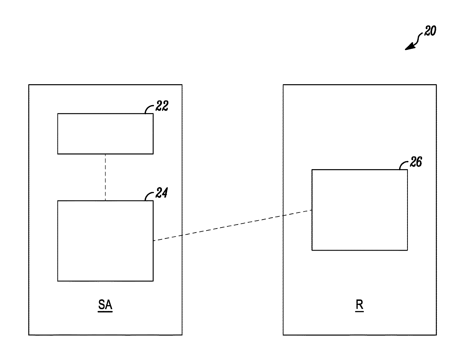
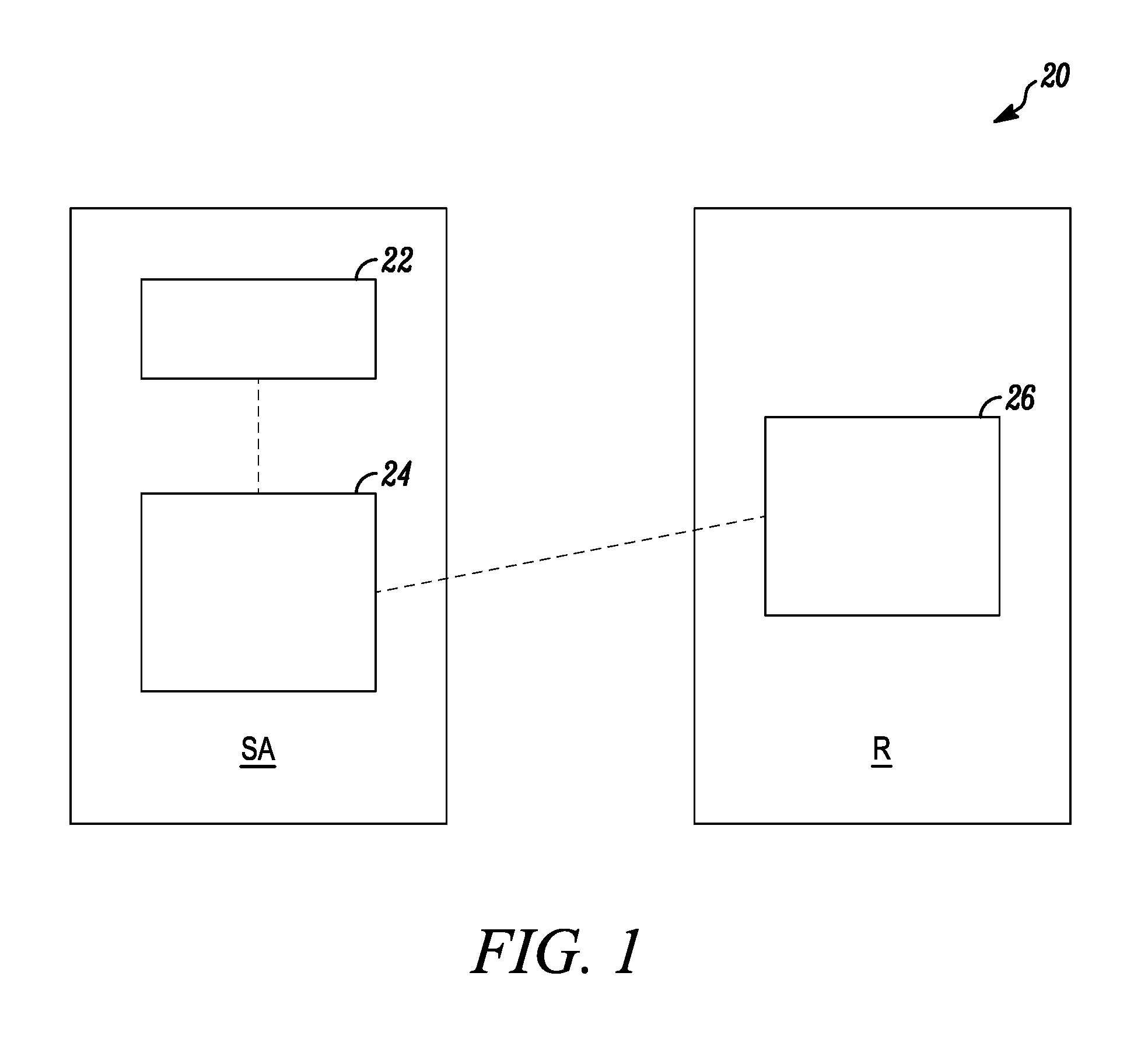
FIG. 1 is a block diagram of a security system in accordance with disclosed embodiments;
FIG. 2 is a block diagram of components of a security system in accordance with disclosed embodiments;
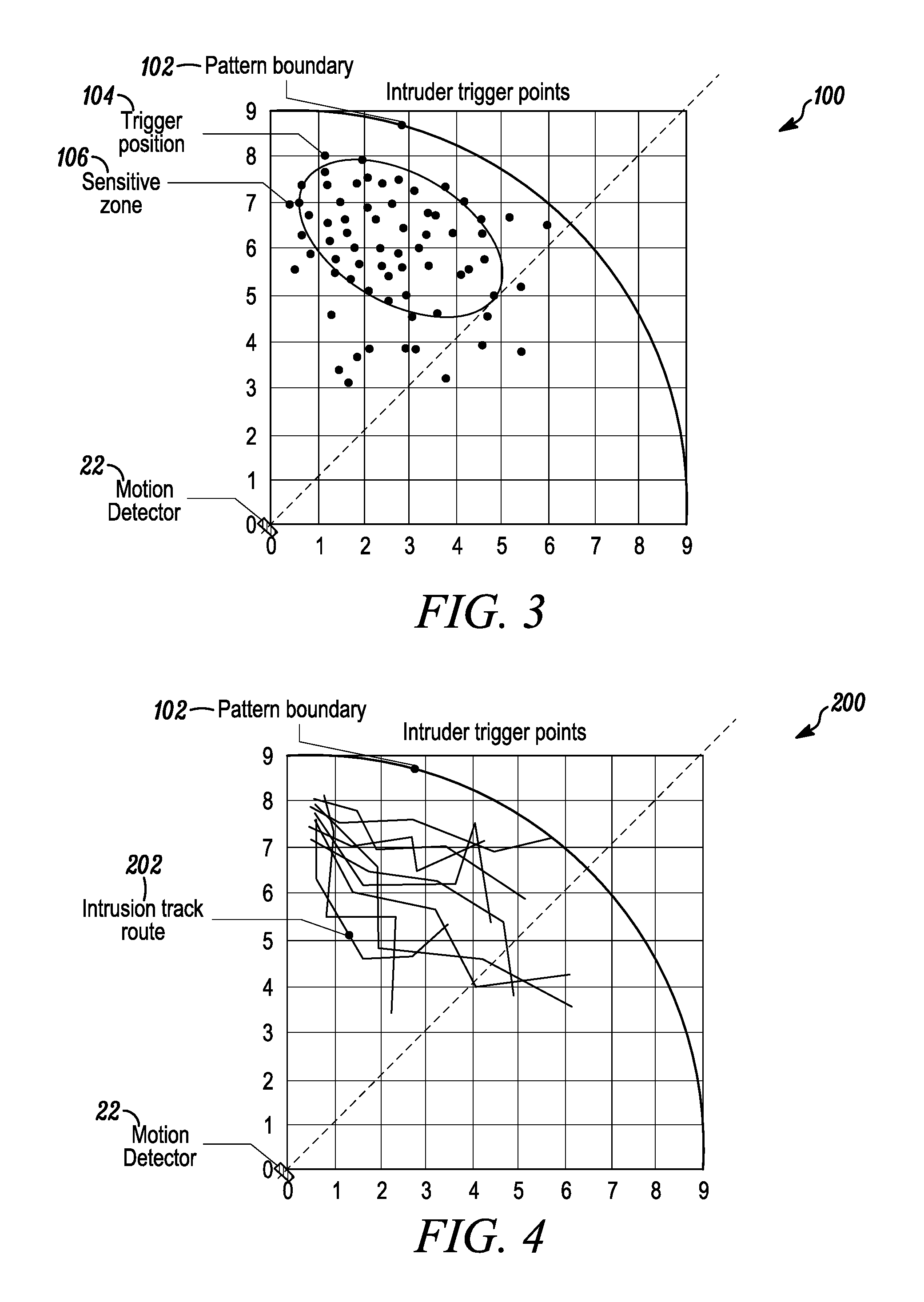
FIG. 3 is a view of a display window in accordance with disclosed embodiments;
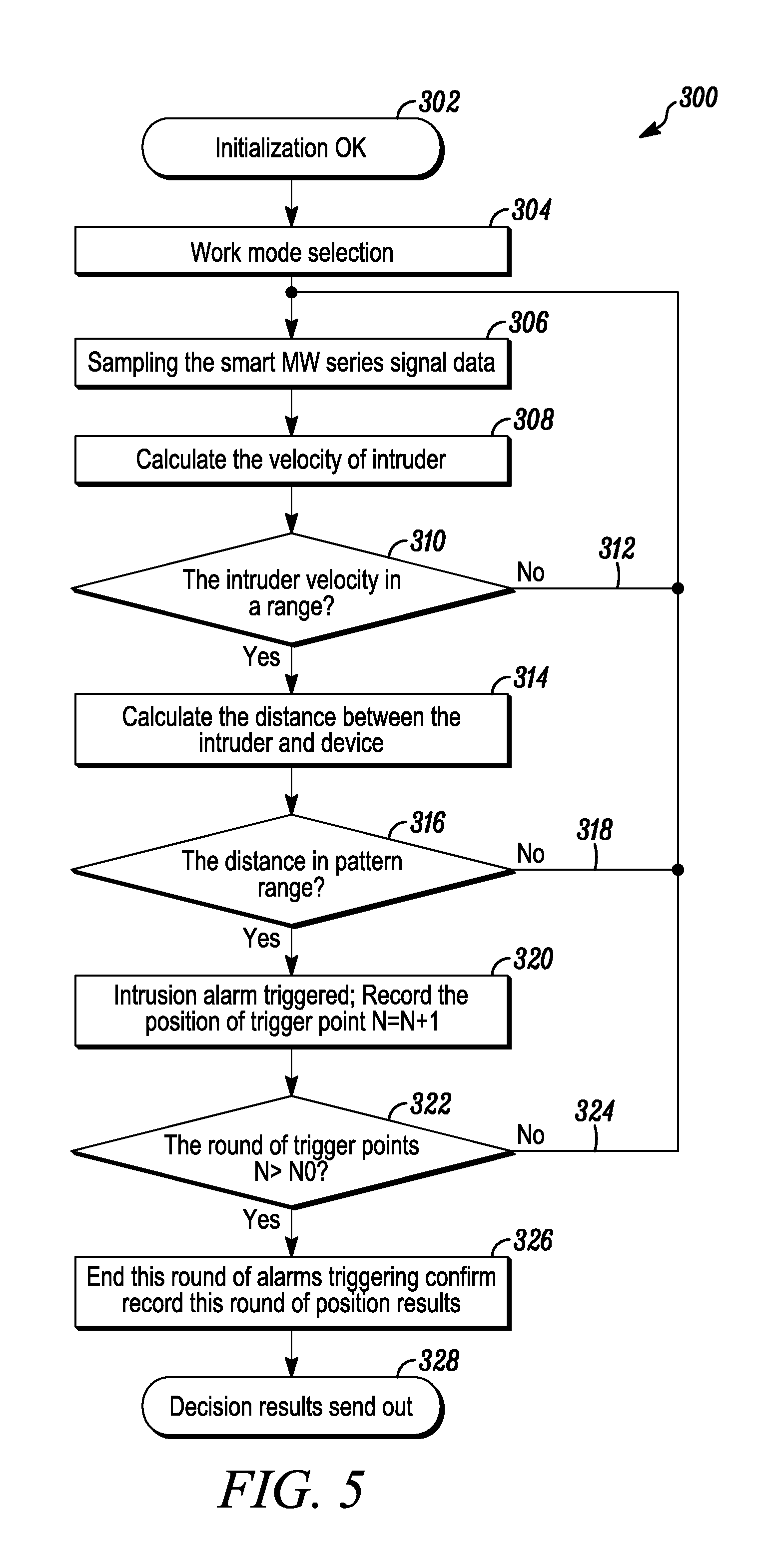
FIG. 4 is a view of a display window in accordance with disclosed embodiments; and
FIG. 5 is a flow diagram of a method in accordance with disclosed embodiments.
DETAILED DESCRIPTION
While this invention is susceptible of an embodiment in many different forms, there are shown in the drawings and will be described herein in detail specific embodiments thereof with the understanding that the present disclosure is to be considered as an exemplification of the principles of the invention. It is not intended to limit the invention to the specific illustrated embodiments.
Embodiments disclosed herein may include systems and methods for monitoring a secured area and determining and verifying a presence of an object or an intruder within the secured area, for example, by identifying a speed, a position, and a moving direction of the object or the intruder. In some embodiments, systems and methods disclosed herein may include a microprocessor unit sampling data from a smart microwave sensor module to detect the data indicative of the presence of the object or the intruder. Such systems and methods also may record a trigger position of the object or the intruder when (1) a velocity of the object or the intruder (the speed) is within a predefined range and (2) a distance of the object or the intruder relative to the smart microwave sensor module (the position) is within a designated protection territory.
Systems and methods disclosed herein are described in connection with a security system. It is to be understood that such a security system may include, but is not limited to the smart microwave sensor module electrically connected to the microprocessor unit and to a user interface device deployed in the secured area or at a remote location removed from the secured area. However, it is to be understood that systems and method disclosed herein are not so limited and may be used in conjunction with other systems, including security systems with security alarms, home automation systems with automatic toilet controls, automatic faucet controls, or automatic door openers, and vehicle systems with vehicle backup warning systems and collision detection systems.
In accordance with disclosed embodiments, the microprocessor unit may sample first signal data from the smart microwave sensor module to detect the presence of the object or the intruder in the secured area. Using the first signal data, the microprocessor unit may calculate a first velocity of the object or the intruder and a first distance between the smart microwave sensor module and the object or the intruder. For example, in some embodiments, the microprocessor unit can employ known techniques relating to smart microwave Doppler theory with related algorithmic processing to calculate the first velocity and the first distance. Furthermore, the microprocessor unit may determine whether the first velocity is within a predefined range and use the first distance to determine whether the object or the intruder is within a designated protection territory for the smart microwave sensor module. When the first velocity is within the predefined range and the first distance indicates the object or the intruder is within the designated protection territory, the microprocessor unit may record a trigger position of the object or the intruder indicative of the current position of the object or the intruder when the first signal data was sampled.
In some embodiments, the microprocessor unit may sample second signal data from the smart microwave sensor module to detect the presence of the object or the intruder in the secured area. Using the second signal data, the microprocessor unit may calculate a second velocity of the object or the intruder and a second distance between the smart microwave sensor module and the object or the intruder. Furthermore, the microprocessor unit may determine whether the second velocity is within the predefined range and use the second distance to determine whether the object or the intruder is within the designated protection territory for the smart microwave sensor module. When the second velocity is within the predefined range and the second distance indicates the object or the intruder is within the designated protection territory, the microprocessor unit may record a second trigger position of the object or the intruder indicative of the current position of the object or the intruder when the second signal data was sampled.
In some embodiments, the microprocessor unit may generate an intrusion track route between the first trigger position and the second trigger position to identify the moving direction of the object or the intruder and a path for the object or the intruder between the first trigger position and the second trigger position. For example, in some embodiments the intrusion track route can include the path with a shortest distance between the first trigger position and the second trigger position.
In some embodiments, the microprocessor unit can transmit one or more signals indicative of the first trigger position, the second trigger position, and the intrusion track route to the user interface device for displaying a rendering of the first trigger position, the second trigger position, and the intrusion track route thereon. Responsive thereto, the user interface device may receive user input confirming the presence of the object or the intruder. For example, the user interface device may receive the user input may responsive to a user evaluating the rendering of the first trigger position, the second trigger position, and the intrusion track route to determine whether the first trigger position, the second trigger position, and the intrusion track route are indicative of a false alarm or a genuine alarm. In some embodiments, the rendering may be displayed on the user interface device within a window that includes a depiction or a demarcation of the designated protection territory relative to the smart microwave sensor unit.
It is to be understood that the user interface device and the microprocessor unit disclosed herein can include a transceiver device and a memory device, each of which can be in communication with control circuitry, one or more programmable processors, and executable control software as would be understood by one of ordinary skill in the art. In some embodiments, the executable control software can be stored on a transitory or non-transitory computer readable medium, including, but not limited to local computer memory, RAM, optical storage media, magnetic storage media, flash memory, and the like, and some or all of the control circuitry, the programmable processors, and the executable control software can execute and control at least some of the methods disclosed herein.
FIG. 1 is a block diagram of a security system 20 in accordance with disclosed embodiments. As seen in FIG. 1, the security system 20 may include a smart microwave sensor module 22 and a microprocessor unit 24 deployed in a secured area SA. The security system 20 may also include a user interface device 26 deployed in a remote location R that communicates with the microprocessor unit 24.
FIG. 2 is a block diagram of the components of the security system 20. As seen in FIG. 2, the smart microwave sensor module 22 may include transmitting and receiving antennas 32, a Monolithic Microwave Integrated Circuit (MMIC) 34, two-level signal-processing circuits 36, such as filters and amplifiers, a digital potentiometer 38 to adjust a gain of a microwave intermediate frequency signal output from the two-level signal-processing circuits 36, and a modulation/waveform generating module 40. In some embodiments, the microprocessor unit 24 may control the modulation/waveform generating module 40 to transmit a VCO control signal to drive the MMIC 34. Furthermore, in some embodiments, the microprocessor unit 24 may sample the microwave intermediate frequency signal output from the two-level signal-processing circuits 36 to determine whether an object or an intruder is present within the secured area SA.
As seen in FIG. 2, the security system 20 may also include a communication module 28 coupling the microprocessor unit 24 to the user interface device 26. Furthermore, the security system 20 may include a passive infrared (PIR) module 30 that may transmit a wake up signal to one or both of the smart microwave sensor module 22 and the microprocessor unit 24 with instructions to exit a low power sleep state or that, in a dual-tech functionality mode, may transmit PIR data to the microprocessor unit 24 indicative of the presence of the object or the intruder within the secured area SA.
FIG. 3 is a view of a display window 100 of the user interface device 26 in accordance with disclosed embodiments. The display window 100 may display a graph identifying a distance from the motion detector 22 in X and Y directions, a demarcation of a pattern boundary 102 on the graph indicative of a limit of a designated projection territory for the smart microwave sensor module 22, and trigger points 104 on the graph indicative of trigger positions at which the presence of the object or the intruder is detected when a velocity of the object or the intruder is within a predefined range and a distance of the object or the intruder relative to the smart microwave sensor module 22 indicates the object or the intruder is within the designated protection territory. In some embodiments, systems and methods disclosed herein can identify a sensitive zone 106 on the graph indicative of a clustering of the trigger points 104, and the sensitive zone 106 can be indicative of a vulnerable area within the designated protection area.
FIG. 4 is a view of a display window 200 of the user interface device 26 in accordance with disclosed embodiments. The display window 200 may display the graph identifying the distance from the motion detector 22 in the X and Y directions and a rendering of intrusion track routes 202 connecting the trigger points 104. In some embodiments, a first time at which the object or the intruder is detected at a first of the trigger points 104 may be closest in time to a second time at which the object or the intruder is detected at a second of the trigger points 104 connected to the first of the trigger points 104 via one of the intrusion track routes 202. Furthermore, in some embodiments, the intrusion track routes 202 can be indicative of a moving direction of the object or the intruder, which facilitates verifying the presence of the object or the intruder prior to triggering an alarm and is an improvement from previously known detectors in which any movement triggers an alarm.
FIG. 5 is a flow diagram of a method 300 in accordance with disclosed embodiments. As seen in FIG. 5, the method 300 can include the microprocessor unit 24 verifying an initialization reset, as in 302, and receiving a work mode selection, as in 304. Then, the method 300 can include the microprocessor unit 24 sampling data from the smart microwave sensor module 22 for processing, as in 306, using the data to calculate the velocity of the object or the intruder, as in 308, and determining whether the velocity is within a first range, as in 310.
When the velocity is outside of the first range, the method 300 can include the microprocessor unit 24 continuing to sample the data from the smart microwave sensor module 22, as in 312. However, when the velocity is within the first preset range, the method 300 can include the microprocessor unit 24 can using the data to calculate the distance between the object or the intruder and the smart microwave sensor module 22, as in 314, and determining whether the distance is within a second range, as in 316, that is, within a designated protection territory of the smart microwave sensor module 24.
When the distance is outside of the second range, the method 300 can include the microprocessor unit 24 continuing to sample the data from the smart microwave sensor module 22, as in 318. However, when the distance is within the second range, the method 300 can include the microprocessor unit 24 triggering an intrusion alarm, recording the trigger position of one of the trigger points 104 indicative of a current position of the object or the intruder when the data that triggered the intrusion alarm was sampled, and incrementing a counter, as in 320. Then, the method 300 can include the microprocessor unit 24 determining whether a value of the counter is greater than a preset threshold NO, as in 322.
When the value of the counter is less than the preset threshold NO, the method 300 can include the microprocessor unit 24 continuing to sample the data from the smart microwave sensor module 22, as in 324. However, when the value of the counter is greater than the preset threshold NO, the method 300 can include the microprocessor unit 24 terminating a current round of alarm triggering and recording the trigger points 104 for the current round, including one of the intrusion track routes 202 connecting at least some of the trigger points 104 for the current round, as in 326. Finally, the method 300 can include the microprocessor unit 24 transmitting data related to the trigger points 104 and the intrusion track routes 202 for display on the display window 100, as in 328.
Although a few embodiments have been described in detail above, other modifications are possible. For example, the steps described above do not require the particular order described or sequential order to achieve desirable results. Other steps may be provided, steps may be eliminated from the described flows, and other components may be added to or removed from the described systems. Other embodiments may be within the scope of the invention.
From the foregoing, it will be observed that numerous variations and modifications may be effected without departing from the spirit and scope of the invention. It is to be understood that no limitation with respect to the specific system or method described herein is intended or should be inferred. It is, of course, intended to cover all such modifications as fall within the spirit and scope of the invention.
* * * * *
References
D00000
D00001
D00002
D00003
D00004
XML
uspto.report is an independent third-party trademark research tool that is not affiliated, endorsed, or sponsored by the United States Patent and Trademark Office (USPTO) or any other governmental organization. The information provided by uspto.report is based on publicly available data at the time of writing and is intended for informational purposes only.
While we strive to provide accurate and up-to-date information, we do not guarantee the accuracy, completeness, reliability, or suitability of the information displayed on this site. The use of this site is at your own risk. Any reliance you place on such information is therefore strictly at your own risk.
All official trademark data, including owner information, should be verified by visiting the official USPTO website at www.uspto.gov. This site is not intended to replace professional legal advice and should not be used as a substitute for consulting with a legal professional who is knowledgeable about trademark law.