On-demand processing pipeline interleaved with temporal processing pipeline
Narsude , et al. O
U.S. patent number 10,437,641 [Application Number 15/796,263] was granted by the patent office on 2019-10-08 for on-demand processing pipeline interleaved with temporal processing pipeline. This patent grant is currently assigned to CISCO TECHNOLOGY, INC.. The grantee listed for this patent is Cisco Technology, Inc.. Invention is credited to Gaurav Gupta, Sundar Iyer, Pavan Mamillapalli, Chetan Narsude, Shadab Nazar, Azeem Suleman.


| United States Patent | 10,437,641 |
| Narsude , et al. | October 8, 2019 |
On-demand processing pipeline interleaved with temporal processing pipeline
Abstract
Aspects of the technology provide systems and methods for interleaving a processing task in a network monitoring appliance. A process of the technology could include steps for identifying operators in the network monitoring appliance, wherein the operators are sequentially arranged to form a processing pipeline, determining an epoch for the processing pipeline, wherein the epoch corresponds with a time duration required for a processing task to traverse the pipeline, and determining a time window in which a supplemental processing task can be interleaved into the processing pipeline, wherein the time window is based on the epoch. Machine-readable media are also provided.
| Inventors: | Narsude; Chetan (Sunnyvale, CA), Gupta; Gaurav (Santa Clara, CA), Suleman; Azeem (San Jose, CA), Nazar; Shadab (Fremont, CA), Mamillapalli; Pavan (San Ramon, CA), Iyer; Sundar (Palo Alto, CA) | ||||||||||
|---|---|---|---|---|---|---|---|---|---|---|---|
| Applicant: |
|
||||||||||
| Assignee: | CISCO TECHNOLOGY, INC. (San
Jose, CA) |
||||||||||
| Family ID: | 64658055 | ||||||||||
| Appl. No.: | 15/796,263 | ||||||||||
| Filed: | October 27, 2017 |
Prior Publication Data
| Document Identifier | Publication Date | |
|---|---|---|
| US 20180365061 A1 | Dec 20, 2018 | |
Related U.S. Patent Documents
| Application Number | Filing Date | Patent Number | Issue Date | ||
|---|---|---|---|---|---|
| 62521685 | Jun 19, 2017 | ||||
| Current U.S. Class: | 1/1 |
| Current CPC Class: | G06F 9/4887 (20130101); G06F 16/951 (20190101); G06F 9/52 (20130101) |
| Current International Class: | G06F 9/46 (20060101); G06F 9/48 (20060101); G06F 9/52 (20060101); G06F 16/951 (20190101) |
| Field of Search: | ;718/1,100-108 |
References Cited [Referenced By]
U.S. Patent Documents
| 4945775 | August 1990 | Adams |
| 5117387 | May 1992 | Nemirovsky |
| 5204829 | April 1993 | Lyu et al. |
| 5835776 | November 1998 | Tirumalai |
| 5867711 | February 1999 | Subramanian |
| 6195676 | February 2001 | Spix |
| 6205468 | March 2001 | Diepstraten |
| 6570564 | May 2003 | Sowizral |
| 6675189 | January 2004 | Rehg |
| 6763380 | July 2004 | Mayton et al. |
| 6975638 | December 2005 | Chen |
| 7003562 | February 2006 | Mayer |
| 7089369 | August 2006 | Emberling |
| 7127686 | October 2006 | Dreschler et al. |
| 7360064 | April 2008 | Steiss et al. |
| 7453886 | November 2008 | Allan |
| 7503046 | March 2009 | Beaumont |
| 7505463 | March 2009 | Schuba et al. |
| 7548967 | June 2009 | Amyot et al. |
| 7552201 | June 2009 | Areddu et al. |
| 7609647 | October 2009 | Turk et al. |
| 7619989 | November 2009 | Guingo et al. |
| 7698561 | April 2010 | Nagendra et al. |
| 7743274 | June 2010 | Langford et al. |
| 7765093 | July 2010 | Li et al. |
| 8010952 | August 2011 | Datla et al. |
| 8073935 | December 2011 | Viswanath |
| 8103480 | January 2012 | Korn et al. |
| 8190719 | May 2012 | Furukawa |
| 8209738 | June 2012 | Nicol et al. |
| 8261339 | September 2012 | Aldridge et al. |
| 8312261 | November 2012 | Rao et al. |
| 8375117 | February 2013 | Venable, Sr. |
| 8441941 | May 2013 | McDade et al. |
| 8479267 | July 2013 | Donley et al. |
| 8484693 | July 2013 | Cox et al. |
| 8494977 | July 2013 | Yehuda et al. |
| 8554883 | October 2013 | Sankaran |
| 8589934 | November 2013 | Makljenovic et al. |
| 8621284 | December 2013 | Kato |
| 8627328 | January 2014 | Mousseau et al. |
| 8693344 | April 2014 | Adams et al. |
| 8693374 | April 2014 | Murphy et al. |
| 8761036 | June 2014 | Fulton et al. |
| 8769543 | July 2014 | Sandstrom |
| 8782182 | July 2014 | Chaturvedi et al. |
| 8824482 | September 2014 | Kajekar et al. |
| 8910143 | December 2014 | Cohen et al. |
| 8914843 | December 2014 | Bryan et al. |
| 8924798 | December 2014 | Jerde et al. |
| 8954993 | February 2015 | Kruglick |
| 9019840 | April 2015 | Salam et al. |
| 9038151 | May 2015 | Chua et al. |
| 9055000 | June 2015 | Ghosh et al. |
| 9106555 | August 2015 | Agarwal et al. |
| 9122523 | September 2015 | Pienaar |
| 9137096 | September 2015 | Yehuda et al. |
| 9225601 | December 2015 | Khurshid et al. |
| 9246818 | January 2016 | Deshpande et al. |
| 9264922 | February 2016 | Gillot et al. |
| 9276877 | March 2016 | Chua et al. |
| 9319300 | April 2016 | Huynh Van et al. |
| 9344348 | May 2016 | Ivanov et al. |
| 9369434 | June 2016 | Kim et al. |
| 9389993 | July 2016 | Okmyanskiy et al. |
| 9405553 | August 2016 | Branson et al. |
| 9444842 | September 2016 | Porras et al. |
| 9497207 | November 2016 | Dhawan et al. |
| 9497215 | November 2016 | Vasseur et al. |
| 9544224 | January 2017 | Chu et al. |
| 9548965 | January 2017 | Wang et al. |
| 9553845 | January 2017 | Talmor et al. |
| 9571502 | February 2017 | Basso et al. |
| 9571523 | February 2017 | Porras et al. |
| 9594640 | March 2017 | Chheda |
| 9596141 | March 2017 | McDowall |
| 9641249 | May 2017 | Kaneriya et al. |
| 9654300 | May 2017 | Pani |
| 9654361 | May 2017 | Vasseur et al. |
| 9654409 | May 2017 | Yadav et al. |
| 9660886 | May 2017 | Ye et al. |
| 9660897 | May 2017 | Gredler |
| 9667645 | May 2017 | Belani et al. |
| 9680875 | June 2017 | Knjazihhin et al. |
| 9686180 | June 2017 | Chu et al. |
| 9686296 | June 2017 | Murchison et al. |
| 9690644 | June 2017 | Anderson et al. |
| 9781004 | October 2017 | Danait et al. |
| 9787559 | October 2017 | Schroeder |
| 9998247 | June 2018 | Choudhury et al. |
| 10084795 | September 2018 | Akireddy et al. |
| 10084833 | September 2018 | McDonnell et al. |
| 10084895 | September 2018 | Kasat et al. |
| 10108516 | October 2018 | Palmer |
| 10191768 | January 2019 | Bishop |
| 2002/0143855 | October 2002 | Traversat et al. |
| 2002/0178246 | November 2002 | Mayer |
| 2003/0229693 | December 2003 | Mahlik et al. |
| 2004/0073647 | April 2004 | Gentile et al. |
| 2004/0168100 | August 2004 | Thottan et al. |
| 2005/0108389 | May 2005 | Kempin et al. |
| 2007/0011629 | January 2007 | Shacham et al. |
| 2007/0124437 | May 2007 | Chervets |
| 2007/0214244 | September 2007 | Hitokoto et al. |
| 2008/0031147 | February 2008 | Fieremans et al. |
| 2008/0117827 | May 2008 | Matsumoto et al. |
| 2008/0133731 | June 2008 | Bradley et al. |
| 2008/0172716 | July 2008 | Talpade et al. |
| 2009/0240758 | September 2009 | Pasko et al. |
| 2009/0249284 | October 2009 | Antosz et al. |
| 2010/0191612 | July 2010 | Raleigh |
| 2010/0198909 | August 2010 | Kosbab et al. |
| 2011/0093612 | April 2011 | Murakami |
| 2011/0295983 | December 2011 | Medved et al. |
| 2012/0054163 | March 2012 | Liu et al. |
| 2012/0198073 | August 2012 | Srikanth et al. |
| 2012/0297061 | November 2012 | Pedigo et al. |
| 2013/0097660 | April 2013 | Das et al. |
| 2013/0191516 | July 2013 | Sears |
| 2014/0019597 | January 2014 | Nath et al. |
| 2014/0177638 | June 2014 | Bragg et al. |
| 2014/0222996 | August 2014 | Vasseur et al. |
| 2014/0304831 | October 2014 | Hidlreth et al. |
| 2014/0307556 | October 2014 | Zhang |
| 2014/0321277 | October 2014 | Lynn, Jr. et al. |
| 2014/0379915 | December 2014 | Yang et al. |
| 2015/0019756 | January 2015 | Masuda |
| 2015/0113143 | April 2015 | Stuart et al. |
| 2015/0124826 | May 2015 | Edsall et al. |
| 2015/0186206 | July 2015 | Bhattacharya et al. |
| 2015/0234695 | August 2015 | Cuthbert et al. |
| 2015/0244617 | August 2015 | Nakil et al. |
| 2015/0271104 | September 2015 | Chikkamath et al. |
| 2015/0295771 | October 2015 | Cuni et al. |
| 2015/0365314 | December 2015 | Hiscock et al. |
| 2015/0381484 | December 2015 | Hira et al. |
| 2016/0020993 | January 2016 | Wu et al. |
| 2016/0021141 | January 2016 | Liu et al. |
| 2016/0026631 | January 2016 | Salam et al. |
| 2016/0036636 | February 2016 | Erickson et al. |
| 2016/0048420 | February 2016 | Gourlay et al. |
| 2016/0078220 | March 2016 | Scharf et al. |
| 2016/0080350 | March 2016 | Chaturvedi et al. |
| 2016/0099883 | April 2016 | Voit et al. |
| 2016/0105317 | April 2016 | Zimmermann et al. |
| 2016/0112246 | April 2016 | Singh et al. |
| 2016/0112269 | April 2016 | Singh et al. |
| 2016/0149751 | May 2016 | Pani et al. |
| 2016/0164748 | June 2016 | Kim |
| 2016/0224277 | August 2016 | Batra et al. |
| 2016/0241436 | August 2016 | Fourie et al. |
| 2016/0254964 | September 2016 | Benc |
| 2016/0267384 | September 2016 | Salam et al. |
| 2016/0323319 | November 2016 | Gourlay et al. |
| 2016/0330076 | November 2016 | Tiwari et al. |
| 2016/0352566 | December 2016 | Mekkattuparamnban et al. |
| 2016/0380892 | December 2016 | Mahadevan et al. |
| 2017/0026292 | January 2017 | Smith et al. |
| 2017/0031800 | February 2017 | Shani et al. |
| 2017/0031970 | February 2017 | Burk |
| 2017/0048110 | February 2017 | Wu et al. |
| 2017/0048126 | February 2017 | Handige Shankar et al. |
| 2017/0054758 | February 2017 | Maino et al. |
| 2017/0063599 | March 2017 | Wu et al. |
| 2017/0093630 | March 2017 | Foulkes |
| 2017/0093664 | March 2017 | Lynam et al. |
| 2017/0093750 | March 2017 | McBride et al. |
| 2017/0093918 | March 2017 | Banerjee et al. |
| 2017/0111259 | April 2017 | Wen et al. |
| 2017/0118167 | April 2017 | Subramanya et al. |
| 2017/0126740 | May 2017 | Bejarano Ardila et al. |
| 2017/0126792 | May 2017 | Halpern et al. |
| 2017/0134233 | May 2017 | Dong et al. |
| 2017/0163442 | June 2017 | Shen et al. |
| 2017/0187577 | June 2017 | Nevrekar et al. |
| 2017/0195187 | July 2017 | Bennett et al. |
| 2017/0206129 | July 2017 | Yankilevich et al. |
| 2017/0222873 | August 2017 | Lee et al. |
| 2018/0069754 | March 2018 | Dasu et al. |
| 2018/0167294 | June 2018 | Gupta et al. |
| 105471830 | Apr 2016 | CN | |||
| 105721193 | Jun 2016 | CN | |||
| 105721297 | Jun 2016 | CN | |||
| 106130766 | Nov 2016 | CN | |||
| 106603264 | Apr 2017 | CN | |||
| 103701926 | Jun 2017 | CN | |||
| WO 2015/014177 | Feb 2015 | WO | |||
| WO 2015/187337 | Dec 2015 | WO | |||
| WO 2016/011888 | Jan 2016 | WO | |||
| WO 2016/039730 | Mar 2016 | WO | |||
| WO 2016/072996 | May 2016 | WO | |||
| WO 2016/085516 | Jun 2016 | WO | |||
| WO 2016/093861 | Jun 2016 | WO | |||
| WO 2016/119436 | Aug 2016 | WO | |||
| WO 2016/130108 | Aug 2016 | WO | |||
| WO 2016/161127 | Oct 2016 | WO | |||
| WO 2017/031922 | Mar 2017 | WO | |||
| WO 2017/039606 | Mar 2017 | WO | |||
| WO 2017/105452 | Jun 2017 | WO | |||
Other References
|
Ghica et al,"Selecting Tracking Principals with Epoch Awareness", ACM, pp. 222-231, 2010 (Year: 2010). cited by examiner . Sun et al, "TCP Performance Optimization for Epoch-based Execution", ACM, pp. 1-7, 2017 (Year: 2017). cited by examiner . Tournavitis et al, Semi-Automatic Extraction and Exploitation of Hierarchical Pipeline Parallelism Using Profiling Information, ACM, pp. 377-388 (Year: 2010). cited by examiner . Chou , "Low-Cost Epoch-Based Correlation Prefetching for Commercial Applications", IEEE, 301-313 (Year: 2007). cited by examiner . Quan et al, "A Task Scheduling Algorithm for Automated Parallel Processing of XQuery", IEEE, 250-254 (Year: 2014). cited by examiner . Schor et al, "Expandable Process Networks to Efficiently Specify and Explore Task, Data, and Pipeline Parallelism", IEEE, pp. 1-10 ( Year: 2013). cited by examiner . Cisco Systems, Inc., "Cisco Application Centric Infrastructure 9ACI Endpoint Groups (EPG) Usage and Design," White Paper, May 2014, pp. 1-14. cited by applicant . Cisco Systems, Inc., "The Cisco Application Policy Infrastructure Controller Introduction: What is the Cisco Application Policy Infrastructure Controller?" Jul. 31, 2014, 19 pages. cited by applicant . Jain, Praveen, et al., "In-Line Distributed and Stateful Security Policies for Applications in a Network Environment," Cisco Systems, Inc., Aug. 16, 2016, 13 pages. cited by applicant . Maldonado-Lopez, Ferney, et al., "Detection and prevention of firewall--rule conflicts on software-defined networking," 2015 7.sup.th International Workshop on Reliable Networks Design and Modeling (RNDM), IEEE, Oct. 5, 2015, pp. 259-265. cited by applicant . Vega, Andres, et al., "Troubleshooting Cisco Application Centric Infrastructure: Analytical problem solving applied to the Policy Driven Data Center," Feb. 15, 2016, 84 pages. cited by applicant . Xia, Wenfeng, et al., "A Survey on Software-Defined Networking," IEEE Communications Surveys and Tutorials, Mar. 16, 2015, pp. 27-51. cited by applicant . Akella, Aditya, et al., "A Highly Available Software Defined Fabric," HotNets-XIII, Oct. 27-28, 2014, Los Angeles, CA, USA, Copyright 2014, ACM, pp. 1-7. cited by applicant . Alsheikh, Mohammad Abu, et al., "Machine Learning in Wireless Sensor Networks: Algorithms, Strategies, and Application," Mar. 19, 2015, pp. 1-23. cited by applicant . Author Unknown, "Aids to Pro-active Management of Distributed Resources through Dynamic Fault-Localization and Availability Prognosis," FaultLocalization-TR01-CADlab, May 2006, pp. 1-9. cited by applicant . Author Unknown, "Requirements for applying formal methods to software-defined networking," Telecommunication Standardization Sector of ITU, Series Y: Global Information Infrastructure, Internet Protocol Aspects and Next-Generation Networks, Apr. 8, 2015, pp. 1-20. cited by applicant . Cisco, "Verify Contracts and Rules in the ACI Fabric," Cisco, Updated Aug. 19, 2016, Document ID: 119023, pp. 1-20. cited by applicant . de Silva et al., "Network-wide Security Analysis," Semantic Scholar, Oct. 25, 2011, pp. 1-11. cited by applicant . Dhawan, Mohan, et al., "SPHINX: Detecting Security Attacks in Software-Defined Networks," NDSS 2015, Feb. 8-11, 2015, San Diego, CA, USA, Copyright 2015 Internet Society, pp. 1-15. cited by applicant . Fayaz, Seyed K., et al., "Efficient Network Reachability Analysis using a Succinct Control Plane Representation," 2016, ratul.org, pp. 1-16. cited by applicant . Feldmann, Anja, et al., "IP Network Configuration for Intradomain Traffic Engineering," Semantic Scholar, accessed on Jul. 20, 2017, pp. 1-27. cited by applicant . Han, Yoonseon, et al., "An Intent-based Network Virtualization Platform for SDN," 2016 I FIP, pp. 1-6. cited by applicant . Han, Wonkyu, et al., "LPM: Layered Policy Management for Software-Defined Networks," Mar. 8, 2016, pp. 1-8. cited by applicant . Kazemian, Peyman, et al., "Real Time Network Policy Checking using Header Space Analysis," USENIX Association, 10th USENIX Symposium on Networked Systems Design and Implementation (NSDI '13) pp. 99-111. cited by applicant . Khatkar, Pankaj Kumar, "Firewall Rule Set Analysis and Visualization, A Thesis Presented in Partial Fulfillment of the Requirements for the Degree Master of Science," Arizona State University, Dec. 2014, pp. 1-58. cited by applicant . Le, Franck, et al., "Minerals: Using Data Mining to Detect Router Misconfigurations," CyLab, Carnegie Mellon University, CMU-CyLab-06-008, May 23, 2006, pp. 1-14. cited by applicant . Liang, Chieh-Jan Mike, et al., "SIFT: Building an Internet of Safe Things," Microsoft, IPSN' 15, Apr. 14-16, 2015, Seattle, WA, ACM 978, pp. 1-12. cited by applicant . Lindem, A., et al., "Network Device YANG Organizational Model draft-rtgyangdt-rtgwg-device-model-01," Network Working Group, Internet--draft, Sep. 21, 2015, pp. 1-33. cited by applicant . Liu, Jason, et al., "A Real-Time Network Simulation Infrastracture Based on Open VPN," Journal of Systems and Software, Aug. 4, 2008, pp. 1-45. cited by applicant . Lopes, Nuno P., et al., "Automatically verifying reachability and well-formedness in P4 Networks," Microsoft, accessed on Jul. 18, 2017, pp. 1-13. cited by applicant . Mai, Haohui, et al., "Debugging the Data Plane with Anteater," SIGCOMM11, Aug. 15-19, 2011, pp. 1-12. cited by applicant . Miller, Nancy, et al., "Collecting Network Status Information for Network-Aware Applications," INFOCOM 2000, pp. 1-10. cited by applicant . Miranda, Joao Sales Henriques, "Fault Isolation in Software Defined Networks," www.gsd.inescid.pt, pp. 1-10. cited by applicant . Moon, Daekyeong, et al., "Bridging the Software/Hardware Forwarding Divide," Berkeley.edu, Dec. 18, 2010, pp. 1-15. cited by applicant . Panda, Aurojit, et al., "SCL: Simplifying Distributed SDN Control Planes," people.eecs.berkeley.edu, Mar. 2017, pp. 1-17. cited by applicant . Shin, Seugwon, et al., "FRESCO: Modular Composable Security Services for Software-Defined Networks," To appear in the ISOC Network and Distributed System Security Symposium, Feb. 2013, pp. 1-16. cited by applicant . Shukla, Apoorv, et al., "Towards meticulous data plane monitoring," kaust.edu.sa, access on Aug. 1, 2017, pp. 1-2. cited by applicant . Tang, Yongning, et al., "Automatic belief network modeling via policy inference for SDN fault localization," Journal of Internet Services and Applications, 2016, pp. 1-13. cited by applicant . Tomar, Kuldeep, et al., "Enhancing Network Security and Performance Using Optimized ACLs," International Journal in Foundations of Computer Science & Technology (IJFCST), vol. 4, No. 6, Nov. 2014, pp. 25-35. cited by applicant . Tongaonkar, Alok, et al., "Inferring Higher Level Policies from Firewall Rules," Proceedings of the 21st Large Installation System Administration Conference (LISA '07), Nov. 11-16, 2007, pp. 1-14. cited by applicant . Yu et al., "A Flexible Framework for Wireless-Based Intelligent Sensor with Reconfigurability, Dynamic adding, and Web interface," Conference Paper, Jul. 24, 2006, IEEE 2006, pp. 1-7. cited by applicant . Zhou, Shijie, et al., "High-Performance Packet Classification on GPU," 2014 IEEE, pp. 1-6. cited by applicant. |
Primary Examiner: Khatri; Anil
Attorney, Agent or Firm: Polsinelli PC
Parent Case Text
CROSS-REFERENCE TO RELATED APPLICATIONS
This application claims the benefit of U.S. Application No. 62/521,685, filed Jun. 19, 2017, entitled "ON-DEMAND PROCESSING PIPELINE INTERLEAVED WITH TEMPORAL PROCESSING PIPELINE", which is incorporated by reference in its entirety.
Claims
What is claimed is:
1. A computer-implemented method for interleaving a processing task in a network monitoring appliance, comprising: identifying a plurality of operators in the network monitoring appliance, wherein the plurality of operators are sequentially arranged to form a sequentially processing pipeline; determining an epoch for the processing pipeline, wherein the epoch corresponds with a time duration required for a processing task to traverse the processing pipeline; and determining a time window in which a supplemental processing task can be interleaved into the processing pipeline, wherein the time window is based on the epoch; interleaving the supplemental processing task into the processing pipeline during the time window.
2. The computer-implemented method of claim 1, further comprising: selecting an idle operator, from among the plurality of operators in the processing pipeline; and wherein the interleaving is executed by the idle operator.
3. The computer-implemented method of claim 2, wherein selecting the idle operator is further based on a type of processing associated with the supplemental processing task.
4. The computer-implemented method of claim 1, wherein determining the time window in which the supplemental processing task can be interleaved into the processing pipeline is further based on an estimated time duration to complete the supplemental processing task.
5. The computer-implemented method of claim 1, wherein the plurality of operators are setup as a Directed Acrylic Graph (DAG).
6. The computer-implemented method of claim 1, wherein each of the plurality of operators are configured to perform a different processing task.
7. The computer-implemented method of claim 1, wherein the network monitoring appliance is coupled to a tenant network, and wherein the processing pipeline is configured to analyze data received from the tenant network to facilitate identification of one or more failure events in the tenant network.
8. A system comprising: one or more processors; a network interface coupled to the processors; and a computer-readable medium coupled to the processors, the computer-readable medium comprising instructions stored therein, which when executed by the processors, cause the processors to perform operations comprising: identifying a plurality of operators in the network monitoring appliance, wherein the plurality of operators are sequentially arranged to form a sequentially processing pipeline; determining an epoch for the processing pipeline, wherein the epoch corresponds with a time duration required for a processing task to traverse the processing pipeline; and determining a time window in which a supplemental processing task can be interleaved into the processing pipeline, wherein the time window is based on the epoch; interleaving the supplemental processing task into the processing pipeline during the time window.
9. The system of claim 8, wherein the processors are further configured to perform operations comprising: selecting an idle operator, from among the plurality of operators in the processing pipeline, based on the time window; and wherein the interleaving is executed by the idle operator.
10. The system of claim 9, wherein selecting the idle operator is further based on a type of processing associated with the supplemental processing task.
11. The system of claim 8, wherein determining the time window in which the supplemental processing task can be interleaved into the processing pipeline is further based on an estimated time duration to complete the supplemental processing task.
12. The system of claim 8, wherein the plurality of operators are setup as a Directed Acrylic Graph (DAG).
13. The system of claim 8, wherein each of the plurality of operators are configured to perform a different processing task.
14. The system of claim 8, wherein the network monitoring appliance is coupled to a tenant network, and wherein the processing pipeline is configured to analyze data received from the tenant network to facilitate identification of one or more failure events in the tenant network.
15. A non-transitory computer-readable storage medium comprising instructions stored therein, which when executed by one or more processors, cause the processors to perform operations comprising: identifying a plurality of operators in the network monitoring appliance, wherein the plurality of operators are sequentially arranged to form a sequentially processing pipeline: determining an epoch for the processing pipeline, wherein the epoch corresponds with a time duration required for a processing task to traverse the processing pipeline; and determining a time window in which a supplemental processing task can be interleaved into the processing pipeline, wherein the time window is based on the epoch; interleaving the supplemental processing task into the processing pipeline during the time window.
16. The non-transitory computer-readable storage medium claim 15, wherein the processors are further configured to perform operations comprising: selecting an idle operator, from among the plurality of operators in the processing pipeline, based on the time window; and wherein the interleaving is executed by the idle operator.
17. The non-transitory computer-readable storage medium of claim 16, wherein selecting the idle operator is further based on a type of processing associated with the supplemental processing task.
18. The non-transitory computer-readable storage medium of claim 15, wherein determining the time window in which the supplemental processing task can be interleaved into the processing pipeline is further based on an estimated time duration to complete the supplemental processing task.
19. The non-transitory computer-readable storage medium of claim 15, wherein the plurality of operators are setup as a Directed Acrylic Graph (DAG).
20. The non-transitory computer-readable storage medium of claim 15, wherein each of the plurality of operators are configured to perform a different processing task.
Description
BACKGROUND
1. Technical Field
The present technology pertains to network configuration and troubleshooting, and more specifically increasing the throughput of a network monitoring appliance by interleaving processing requests into a temporal processing pipeline.
2. Introduction
Network configurations for large data center networks are often specified at a centralized controller. The controller can realize the intent in the network by programming switches and routers in the data center according to the specified network configurations. Network configurations are inherently very complex, and involve low level as well as high level configurations of several layers of the network such as access policies, forwarding policies, routing policies, security policies, QoS policies, etc. Given such complexity, the network configuration process is error prone.
BRIEF DESCRIPTION OF THE DRAWINGS
In order to describe the manner in which the above-recited and other advantages and features of the disclosure can be obtained, a more particular description of the principles briefly described above will be rendered by reference to specific embodiments thereof which are illustrated in the appended drawings. Understanding that these drawings depict only exemplary embodiments of the disclosure and are not therefore to be considered to be limiting of its scope, the principles herein are described and explained with additional specificity and detail through the use of the accompanying drawings in which:
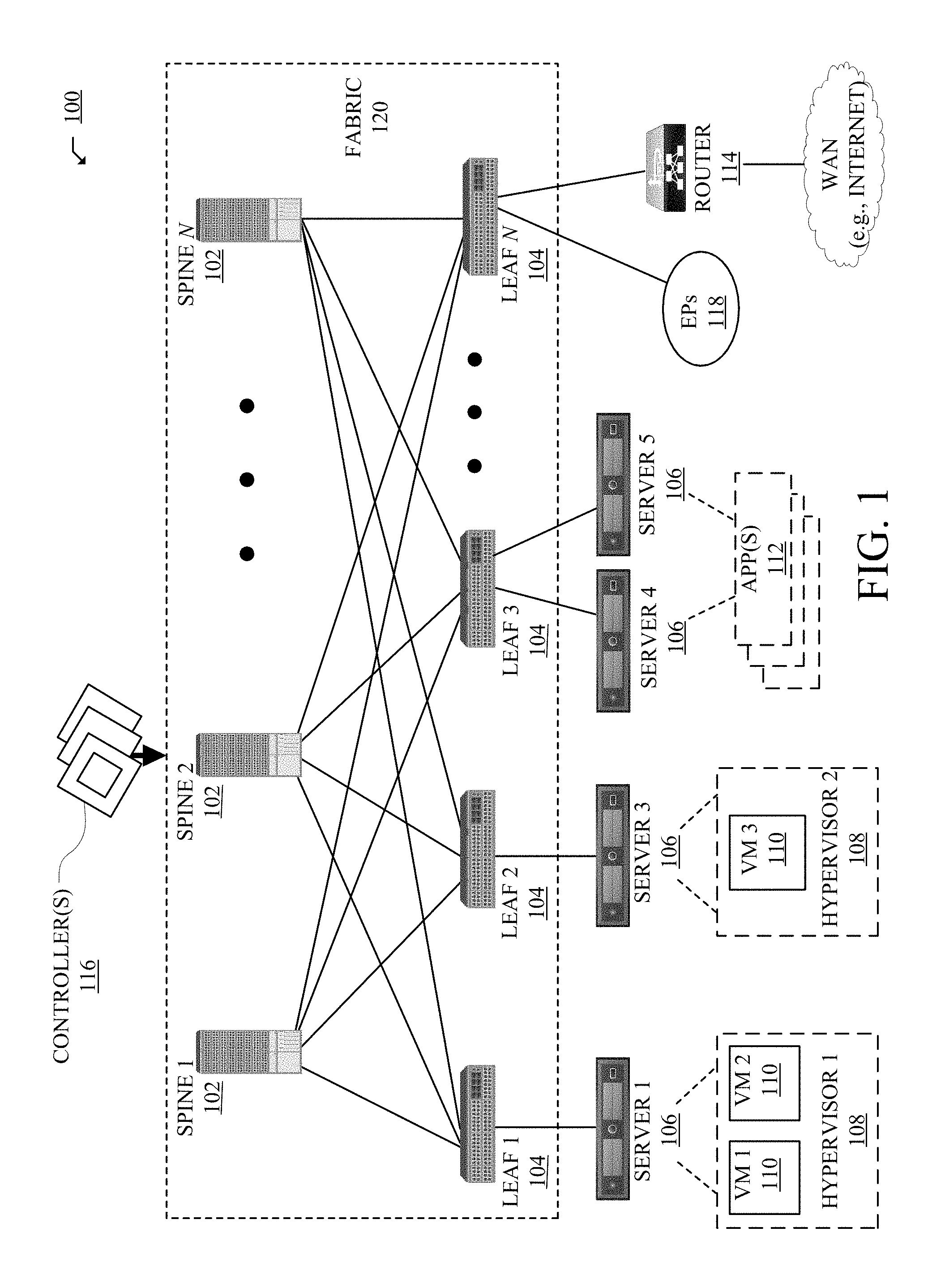
FIG. 1 illustrates an example network environment in which some aspects of the technology can be implemented.
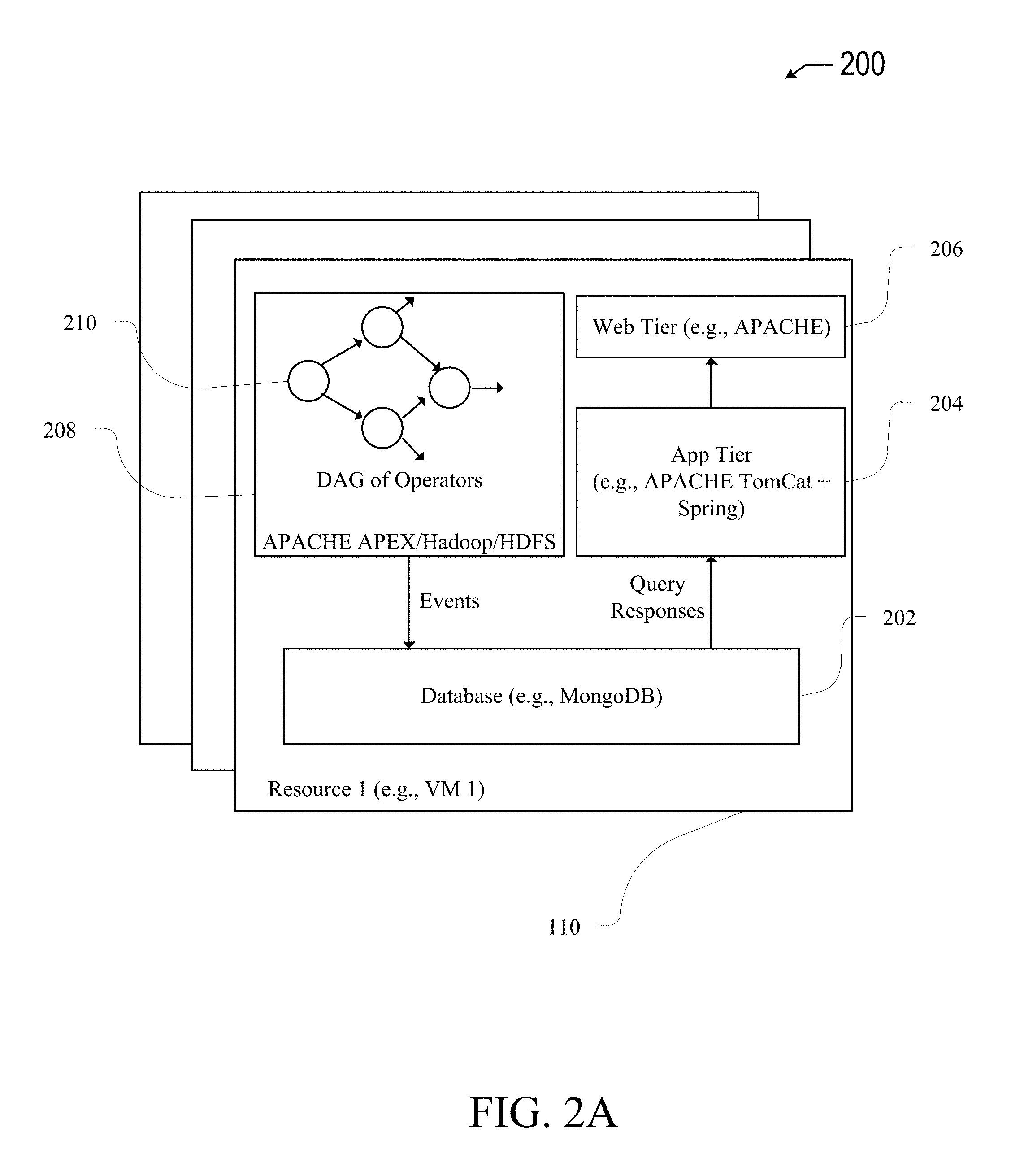
FIG. 2A illustrates an example network assurance appliance, according to some aspects of the technology.
FIG. 2B illustrates an example Directed Acrylic Graph (DAG) of operators used to form a processing pipeline for a network monitoring appliance, according to some aspects of the technology.
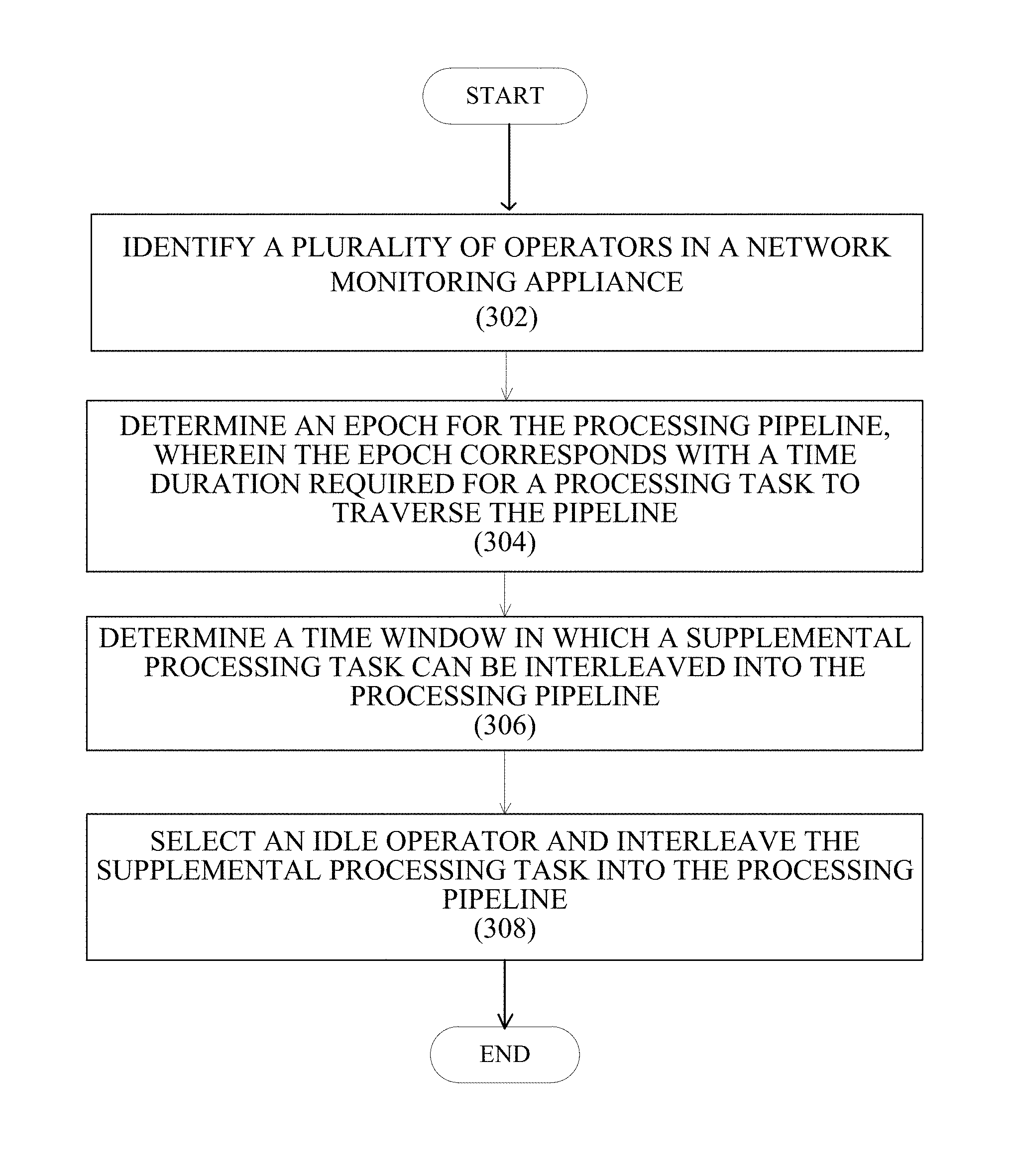
FIG. 3 illustrates steps of an example process interleaving a supplemental processing task into a processing pipeline, according to some aspects of the technology.
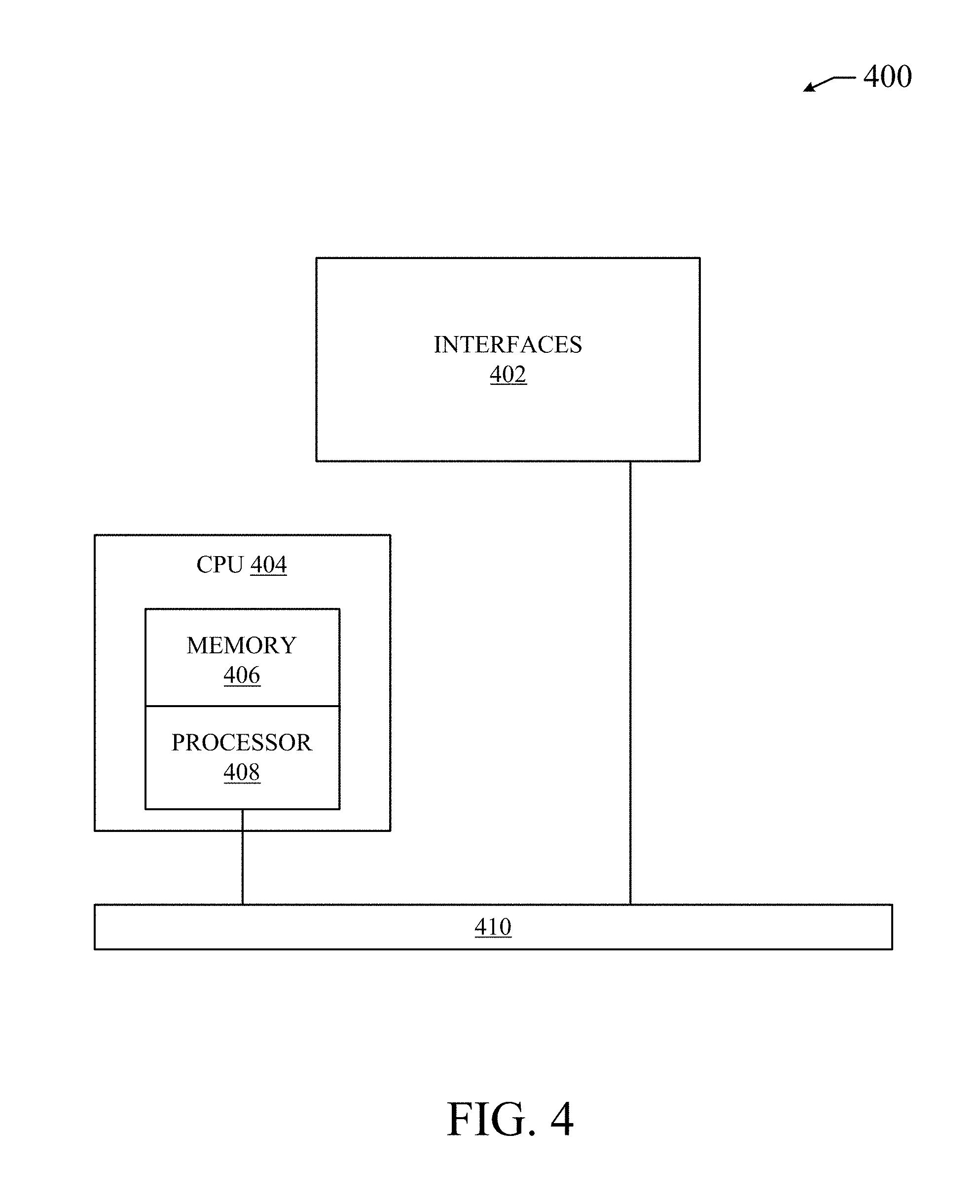
FIG. 4 illustrates an example network device in accordance with various embodiments.
FIG. 5 illustrates an example computing device in accordance with various embodiments.
DETAILED DESCRIPTION
The detailed description set forth below is intended as a description of various configurations of the disclosed technology and is not intended to represent the only configurations in which the technology can be practiced. The appended drawings are incorporated herein and constitute a part of the detailed description. The detailed description includes specific details for the purpose of providing a more thorough understanding of the subject technology. However, it will be clear and apparent that the subject technology is not limited to the specific details set forth herein and may be practiced without these details. In some instances, structures and components are shown in block diagram form in order to avoid obscuring the concepts of the subject technology.
Additional features and advantages of the disclosure will be set forth in the description which follows, and in part will be obvious from the description, or can be learned by practice of the herein disclosed principles. The features and advantages of the disclosure can be realized and obtained by means of the instruments and combinations particularly pointed out in the appended claims. These and other features of the disclosure will become more fully apparent from the following description and appended claims, or can be learned by the practice of the principles set forth herein.
Overview:
In some network implementations, one or more network systems (e.g., "network appliances"), can be configured to be connected to and monitor the network fabric. Such deployments can be used to help troubleshoot customer (e.g. tenant) networking issues, to ensure conformity with agreed-upon networking policies, and to ensure an overall high quality experience. In some monitoring appliance deployments, processing is performed sequentially by an ordered series of independent applications or "operators," that form a processing pipeline. Each operator can be associated with a different processing task that is performed for each received request. Once processing is completed, the request is provided to a next operator in the pipeline.
One limitation of conventional monitoring appliance operation is that pipeline processing begins at predetermined points in a fixed time-period or processing "epoch." Thus, any particular operator may sit idle, until a processing request has been completed by downstream operators in the pipeline, and a new epoch is begun.
Description
Aspects of the subject technology address the foregoing limitations by providing systems and methods increasing the pipeline throughput by interleaving processing requests into the temporal processing chain, for example, to utilize idle operator processing capabilities.
Each operator in the processing chain is configured to perform its processing capability to a received request upon receipt of a "begin-window" signal, and to end processing and return an "end-window" signal once its processing is complete. That is, idleness for any particular operator can be determined based on the receipt of an end-window signal for that operator.
Knowing the idleness state of various operators in the processing chain can be used to determine when additional requests may be interleaved into the chain. By way of example, if a first operator in the processing pipeline releases an end-window signal, then the first operator can be available to receive additional processing requests, rather than sit idle.
FIG. 1, which illustrates a diagram of an example network environment 100, such as a data center in which a processing pipeline of the technology may be implemented. Network 100 can include Fabric 120 that can represent the physical layer or infrastructure (e.g., underlay) of the network 100. Fabric 120 can include Spines 102 (e.g., spine routers or switches) and Leafs 104 (e.g., leaf routers or switches) which can be interconnected for routing traffic in the Fabric 120. The Spines 102 can interconnect the Leafs 104 in the Fabric 120, and the Leafs 104 can connect the Fabric 120 to the overlay portion of the network 100, which can include application services, servers, virtual machines, containers, endpoints, etc. Thus, network connectivity in the Fabric 120 can flow from Spines 102 to Leafs 104, and vice versa. Leafs 104 can be, for example, top-of-rack ("ToR") switches, aggregation switches, gateways, ingress and/or egress switches, provider edge devices, and/or any other type of routing or switching device.
Leafs 104 can be responsible for routing and/or bridging tenant or customer packets and applying network policies. Network policies can be driven by the one or more controllers 116 and/or the Leafs 104. The Leafs 104 can connect Servers 106, Hypervisors 108, Virtual Machines (VMs) 110, Applications 112, Endpoints 118, External Routers 114, etc., with the Fabric 120. For example, Leafs 104 can encapsulate and decapsulate packets to and from Servers 106 in order to enable communications throughout the network 100, including the Fabric 120. Leafs 104 can also provide any other devices, services, tenants, or workloads with access to the Fabric 120.
Applications 112 can include software applications, services, operators, containers, appliances, functions, service chains, etc. For example, Applications 112 can include a firewall, a database, a CDN server, an IDS/IPS, a deep packet inspection service, a message router, a virtual switch, etc. VMs 110 can be virtual machines hosted by Hypervisors 108 running on Servers 106. VMs 110 can include workloads running on a guest operating system on a respective server. Hypervisors 108 can provide a layer of software, firmware, and/or hardware that creates and runs the VMs 110. Hypervisors 108 can allow VMs 110 to share hardware resources on Servers 106, and the hardware resources on Servers 106 to appear as multiple, separate hardware platforms. Moreover, Hypervisors 108 on Servers 106 can each host one or more VMs 110.
In some cases, VMs 110 and/or Hypervisors 108 can be migrated to other Servers 106. Servers 106 can similarly be migrated to other locations in the network environment 100. For example, a server connected to a specific leaf can be changed to connect to a different or additional leaf. Such configuration or deployment changes can involve modifications to settings and policies that are applied to the resources being migrated.
Servers 106, Hypervisors 108, and/or VMs 110 can represent a tenant or customer space. Tenant space can include workloads, services, applications, devices, and/or resources that are associated with one or more clients or subscribers. Accordingly, traffic in the network environment 100 can be routed based on specific tenant policies, spaces, agreements, configurations, etc. Moreover, addressing can vary between one or more tenants. In some configurations, tenant spaces can be divided into logical segments and/or networks and separated from logical segments and/or networks associated with other tenants. Addressing, policy, and configuration information between tenants can be managed by one or more controllers 116.
Policies, configurations, settings, etc., in the network can be implemented at the application level, the physical level, and/or both. For example, one or more controllers 116 can define a policy model at the application level which defines policies and other settings for groups of applications or services, such as endpoint groups. In some addition, the Leafs 104, as well as other physical devices such as physical servers or Spines 102, can apply specific policies to traffic. For example, Leafs 104 can apply specific policies or contracts to traffic based on tags or characteristics of the traffic, such as protocols associated with the traffic, applications or endpoint groups associated with the traffic, network address information associated with the traffic, etc.
In some examples, network 100 can be configured according to a particular software-defined network (SDN) solution. The network 100 can deploy one or more SDN solutions, such as CISCO Application Centric Infrastructure (ACI) or VMWARE NSX solutions. These example SDN solutions are briefly described below.
Application Centric Infrastructure (ACI) is an example SDN solution that can be implemented in network 100. ACI can provide an application policy-based solution through scalable distributed enforcement. ACI supports integration of physical and virtual environments under a declarative policy model for networks, servers, services, security, requirements, etc. For example, the ACI framework implements End Point Groups (EPGs), which can include a collection of endpoints or applications that share common policy requirements, such as security, QoS, services, etc. Endpoints can be virtual/logical or physical devices, such as VMs and bare-metal physical servers that are connected to the network 100. Endpoints can have one or more attributes such as VM name, guest OS name, a security tag, etc. Application policies can be applied between EPGs, instead of endpoints directly, in the form of contracts. The Leafs 104 can classify incoming traffic into different EPGs. The classification can be based on, for example, a network segment identifier such as a VLAN ID, VXLAN Network Identifier (VNID), NVGRE Virtual Subnet Identifier (VSID), MAC address, IP address, etc.
In some cases, classification in the ACI infrastructure can be implemented by Application Virtual Switches (AVS), which can run on a host, and physical hosts. For example, an AVS can classify traffic based on specified attributes, and tag packets of different attribute EPGs with different identifiers, such as network segment identifiers (e.g., VLAN ID). Finally, Leafs 104 can tie packets with their attribute EPGs based on their identifiers and enforce policies, which can be implemented and/or managed by one or more controllers 116, such as an application policy infrastructure controller (APIC). The Leaf 104 can classify to which EPG the traffic from a host belong and enforce policies accordingly.
Another example SDN solution is based on VMWare NSX. With VMWare NSX, hosts can run a distributed firewall (DFW) which can classify and process traffic. Consider a case where three types of VMs, namely, application, database and web VMs, are put into a single layer-2 network segment. Traffic protection can be provided within the network segment based on the VM type. For example, HTTP traffic can be allowed among web VMs, and disallowed between a web VM and an application or database VM. To classify traffic and implement policies, VMWARE NSX can implement security groups, which can be used to group the specific VMs (e.g., web VMs, application VMs, database VMs). DFW rules can be configured to implement policies for the specific security groups. To illustrate, from our previous example, DFW rules can be configured to block HTTP traffic between web, application, and database security groups.
Network 100 may deploy different hosts via the Leafs 104, Servers 106, Hypervisors 108, VMs 110, Applications 112, Controllers 116, and/or Endpoints 118, such as VMware ESXi hosts, Windows Hyper-V hosts, bare metal physical hosts, etc. The network 100 may interoperate with a wide variety of Hypervisors 108, Servers 106 (e.g., physical and/or virtual servers), SDN orchestration platforms, etc. The network 100 may implement a declarative model to allow its integration with application design and holistic network policy.
One or more controllers 116 can provide centralized access to fabric information, application configuration, resource configuration, application-level policy modeling for a software-defined network (SDN) infrastructure, integration with management systems or servers, etc. The one or more controllers 116 can form a control plane that interfaces with an application plane via northbound APIs and a data plane via southbound APIs. In some examples, the one or more controllers 116 can include SDN controllers or managers, such as an application policy infrastructure controller (APIC) or a vCenter NSX Manager.
Controllers 116 can define and manage application-level model(s) for policies in the network 100. In some cases, application or device policies can also be managed and/or defined by other components in the network. For example, a hypervisor or virtual appliance, such as a VM or container, can run a server or management tool to manage software and services in the network 100, including policies and settings for virtual appliances.
As referenced herein, the term "hosts" can refer to servers 106 (e.g., physical or logical), Hypervisors 108, VMs 110, containers (e.g., Applications 112), EPs 118, etc., and can run or include any type of server or application solution. Non-limiting examples of "hosts" can include DVS virtual servers, vCenter and NSX Managers, bare metal physical hosts, AVS hosts, Hyper-V hosts, VMs, Docker Containers, Virtual Routers/Switches (e.g., VPP), etc.
FIG. 2A illustrates an example network assurance appliance. In this example, Appliance 200 can include k VMs 110 operating in cluster mode. VMs are used in this example for explanation purposes. However, it should be understood that other configurations are also contemplated herein, such as use of containers, bare metal devices, Endpoints 122, or any other physical or logical systems. Moreover, while FIG. 2A illustrates a cluster mode configuration, other configurations are also contemplated herein, such as a single mode configuration (e.g., single VM, container, or server) or a service chain for example.
Appliance 200 can run on one or more Servers 106, VMs 110, Hypervisors 108, EPs 122, Leafs 104, Controllers 116, or any other system or resource. For example, Assurance Appliance 200 can be a logical service or application running on one or more VMs 110 in Network Environment 100.
Appliance 200 can include Data Framework 208, which can be based on, for example, APACHE APEX or HADOOP file system (e.g., HDFS). In some cases, assurance checks can be written as individual operators that reside in Data Framework 208. This enables a natively horizontal scale-out architecture that can scale to arbitrary number of switches in Fabric 120 (e.g., ACI fabric).
Appliance 200 can poll Fabric 120 at a configurable periodicity (e.g., an epoch). The analysis workflow can be setup as a DAG (Directed Acyclic Graph) of Operators 210, where data flows from one operator to another and eventually results are generated and persisted to Database 202 for each interval (e.g., each epoch). Operators 210 in Data Framework 208 (e.g., APEX/Hadoop) can together support assurance operations. It is understood that the topological ordering of operators in the DAG configuration proceeds sequentially, beginning with a first operator in the pipeline, and proceeding to a last operator in the pipeline.
In practice, processing tasks received by the processing pipeline proceed in a sequential order, where processing by a given operator cannot begin until processing by a previous operator is concluded. As discussed above, the processing status of a given operator can be indicated by use of signals indicating a "begin-window", after which processing by the operator is performed, and an "end-window", after which operator processing has ended.
Additional (supplemental) processing tasks can be interleaved into the processor pipeline, for example, at a time that it is known that the receiving operators are idle. The idleness state of a receiving operator may be inferred based on the epoch duration of the pipeline, as well as timing of end-window signals for the receiving operator. By way of example, suppose that a processing pipeline consisting of 4 operators, each with a processing time of approximately five-minutes, and that is configured to receive periodic processing tasks at 15 minute intervals. It may be inferred that the pipeline may receive supplemental processing tasks at the first operator during a time window of about 5 minutes after the first operator indicates an end-window. That is, the availability to interleave supplemental processing tasks can be determined based on the epoch time for the pipeline, a periodicity of routinely received processing tasks (e.g., from a tenant network), known processing times for each operator, and/or estimates of processing time required for the supplemental processing task.
In another implementation, operator idleness may be determined based on end-window and begin-window signals, as well as a known periodicity of routinely received processing tasks. Further to the above example, if processing tasks are received from a tenant network at approximately 20 minute intervals, then a supplemental processing task may be provided to a first operator in the pipeline up to 15 minutes after the end-window signal is received.
FIG. 2B illustrates an example of a data processing pipeline 201 formed from multiple operators sequentially organized in a Directed Acrylic Graph (DAG) topology. Pipeline 201 includes operators A, B, C, D, E and F, each configured to perform an associated processing task, and to output a processing result to a next operator in pipeline 201. Therefore, the epoch of the illustrated configuration is the time required for a processing task to begin processing at operator A, and to end operator F.
It is understood that a processing pipeline of the technology can have a greater (or fewer) number of operators than are illustrated in FIG. 2B. Additionally, the arrangement or sequence of operators can vary depending on implementation. Although operators A-F can represent different functions or applications, in some aspects, two or more operators may be configured to perform the same (or a similar) function.
Depending on the type of processing required for a supplemental processing task, the request may be interleaved into the processing pipeline at a downstream operator. By way of example, if processing required for a supplemental processing task can be performed by operator C, and it is determined that operator C is idle (e.g., operator C has issued an end-window signal), a supplemental processing task may be injected into pipeline 201 at operator C, skipping operators A and B. As discussed above with respect to FIG. 2A, the selection of an idle operator, and interleaving of a supplemental processing task into the pipeline can be based on a variety of factors, including but not limited to: determinations idleness for one or more operators in the pipeline, an epoch of the pipeline, a known cost associated with the supplemental processing task, and/or signals received by one or more operators (e.g., end-window and/or begin-window signals).
Referring back to FIG. 2A, it is understood that a network monitoring appliance 200 can perform other types of assurance operations using operators 210. Below are non-limiting examples of assurance operations that can be performed by Assurance Appliance 200 via Operators 210.
Security Policy Adherence:
Assurance Appliance 200 can check to make sure the configurations or specification that reflect a user's (e.g., administrator's) intent for the network, including for example the security policies and customer-configured contracts, are correctly implemented and/or rendered, and thus properly implemented and rendered by the fabric members (e.g., Leafs 104), and report any errors, contract violations, or irregularities found.
Static Policy Analysis:
Assurance Appliance 200 can check for issues in the specification of the user's intent or intents (e.g., identify contradictory or conflicting policies).
TCAM Utilization:
Ternary Content-Addressable Memory (TCAM) is a scarce resource in the fabric (e.g., Fabric 120). However, Assurance Appliance 200 can analyze the TCAM utilization by the network data (e.g., Longest Prefix Match (LPM) tables, routing tables, VLAN tables, BGP updates, etc.), Contracts, Logical Groups 118 (e.g., EPGs), Tenants, Spines 102, Leafs 104, and other dimensions in Network Environment 100 and/or objects in MIM 200, to provide a network operator or user visibility into the utilization of this scarce resource. This can greatly help for planning and other optimization purposes.
Endpoint Checks:
In some aspects, assurance Appliance 200 can validate that the fabric (e.g. fabric 120) has no inconsistencies in the Endpoint information registered (e.g., two leafs announcing the same endpoint, duplicate subnets, etc.), among other such checks.
Tenant Routing/Forwarding Checks:
Assurance Appliance 200 can validate that BDs, VRFs, subnets (both internal and external), VLANs, contracts, filters, applications, EPGs, etc., are correctly programmed.
Infrastructure Routing:
Assurance Appliance 200 can validate that infrastructure routing (e.g., IS-IS protocol) has no convergence issues leading to black holes, loops, flaps, and other problems.
MP-BGP Route Reflection Checks:
The network fabric (e.g., Fabric 120) can interface with other external networks and provide connectivity to them via one or more protocols, such as Border Gateway Protocol (BGP), Open Shortest Path First (OSPF), etc. The learned routes are advertised within the network fabric via, for example, MP-BGP. These checks can ensure that a route reflection service via, for example, MP-BGP (e.g., from Border Leaf) does not have health issues.
FIG. 3 illustrates steps of an example process interleaving a supplemental processing task into a processing pipeline, according to some aspects of the technology. Process 300 begins with step 302 in which multiple operators running in a monitoring appliance are identified, e.g., by a network controller. Further to the examples discussed above with respect to FIGS. 1 and 2, the operators may be processes supported by various network devices, such as VMs or network containers, and that are configured to provide a processing pipeline used to monitor a tenant network. In some aspects, operator identification can include determinations of various statistical parameters relating to one or more of the operators. By way of example, average processing times, application function, and/or operator co-dependence information may be determined for each operator in the pipeline.
In step 304, an epoch of the processing pipeline is determined. An epoch of the pipeline can be determined in different ways, depending on implementation. In some aspects, the epoch duration may be determined by multiple measurements of end-to-end processing, for example, that are performed in the course of normal operation in a tenant network deployment. In other aspects, the epoch may be determined based on processing time estimates for each of the constituent operators. Additionally, the determined epoch may be determined as a function of the processing load that is introduced. By way of example, larger processing loads may correlate with longer epochs, as compared to smaller relative processing loads.
In step 306, a time window in which a supplemental processing task can interleaved into the processing timeline is determined. Because the time window may be operator specific, such determinations can be based upon which operator in the pipeline is to receive the supplemental processing task. That is, the time window may be a function of the type of processing that is required for the supplemental processing task. As discussed above with respect to FIGS. 2A and 2B, the determined time window can represent a temporal opportunity in which supplemental processing tasks can be interleaved i.e., during otherwise idle operator periods.
In step 308, an idle operator is selected for receipt of the supplemental processing request, and the supplemental processing request is interleaved into the processing pipeline via the selected idle operator. After being interleaved into the processing pipeline, the supplemental processing task is passed sequentially to each down-stream operator in the sequential pipeline. By way of example, referring to FIG. 2B, if operator C receives the supplemental processing request, upon completion of processing by operator C, the supplemental processing task is passed to operator E and then to operator F, after which the processing is complete.
FIG. 4 illustrates an example network device 400 suitable for implementing a network appliance of the subject technology. Network device 400 includes a central processing unit (CPU) 404, interfaces 402, and a bus 410 (e.g., a PCI bus). When acting under the control of appropriate software or firmware, the CPU 404 is responsible for executing packet management, error detection, and/or routing functions. CPU 404 accomplishes all these functions under the control of software including an operating system and any appropriate applications software. CPU 404 may include one or more processors 408, such as a processor from the INTEL X86 family of microprocessors. In some cases, processor 408 can be specially designed hardware for controlling the operations of network device 400. In some cases, a memory 406 (e.g., non-volatile RAM, ROM, etc.) also forms part of CPU 404. However, there are many different ways in which memory could be coupled to the system.
The interfaces 402 are typically provided as modular interface cards (sometimes referred to as "line cards"). They can control the sending and receiving of data packets over the network and sometimes support other peripherals used with the network device 400. Among the interfaces that may be provided are Ethernet interfaces, frame relay interfaces, cable interfaces, DSL interfaces, token ring interfaces, and the like. In addition, various very high-speed interfaces may be provided such as fast token ring interfaces, wireless interfaces, Ethernet interfaces, Gigabit Ethernet interfaces, ATM interfaces, HSSI interfaces, POS interfaces, FDDI interfaces, WIFI interfaces, 3G/4G/5G cellular interfaces, CAN BUS, LoRA, and the like. Generally, these interfaces may include ports appropriate for communication with the appropriate media. In some cases, they may also include an independent processor and, in some instances, volatile RAM. The independent processors may control such communications intensive tasks as packet switching, media control, signal processing, crypto processing, and management. By providing separate processors for the communications intensive tasks, these interfaces allow the master microprocessor 404 to efficiently perform routing computations, network diagnostics, security functions, etc.
Although the system shown in FIG. 4 is one specific network device of the present invention, it is by no means the only network device architecture on which the present invention can be implemented. For example, an architecture having a single processor that handles communications as well as routing computations, etc., is often used. Further, other types of interfaces and media could also be used with the network device 400.
Regardless of the network device's configuration, it may employ one or more memories or memory modules (including memory 406) configured to store program instructions for the general-purpose network operations and mechanisms for roaming, route optimization and routing functions described herein. The program instructions may control the operation of an operating system and/or one or more applications, for example. The memory or memories may also be configured to store tables such as mobility binding, registration, and association tables, etc. Memory 406 could also hold various software containers and virtualized execution environments and data.
In some implementations, the program instructions may be configured to cause CPU 404 and/or processor 408 to perform operations for simulating failure events in a tenant network. In particular, the program instructions can cause CUP 404 and/or processor 408 to perform operations for identifying, by a network controller, a plurality of operators running in a network monitoring appliance, instantiating, by the network controller, a plurality of sensors, wherein each of the plurality of sensors is associated with a respective one of the plurality of operators, and wherein each sensor is configured to capture error log data of its corresponding operator, and aggregating, by the network controller, error log data from two or more of the plurality of sensors. In some aspects, a method of the disclosed technology may further include steps for automatically identifying, by the controller, a malfunction in at least one operator from among the plurality of operators in the network monitoring appliance. In some aspects, the error log data may be aggregated from the two or more of the plurality of sensors provides information regarding a malfunction in a tenant network coupled to the network monitoring appliance.
Network device 400 can also include an application-specific integrated circuit (ASIC), which can be configured to perform routing and/or switching operations. The ASIC can communicate with other components in the network device 400 via the bus 410, to exchange data and signals and coordinate various types of operations by the network device 400, such as routing, switching, and/or data storage operations, for example.
FIG. 5 illustrates a computing architecture 500 wherein the components of the system are in electrical communication with each other via connection 505, such as a bus. System 500 includes a processing unit (CPU or processor) 510 and a system connection 505 that couples various system components including system memory 515, such as read only memory (ROM) 520 and random access memory (RAM) 525, to processor 510. System 500 can include a cache of high-speed memory connected directly with, in close proximity to, or integrated as part of the processor 510. The system 500 can copy data from the memory 515 and/or the storage device 530 to the cache 512 for quick access by processor 510. In this way, the cache can provide a performance boost that avoids processor 510 delays while waiting for data. These and other modules can control or be configured to control the processor 510 to perform various actions. Other system memory 515 may be available for use as well. The memory 515 can include multiple different types of memory with different performance characteristics. The processor 510 can include any general purpose processor and a hardware or software service, such as service 1 532, service 2 534, and service 3 536 stored in storage device 530, configured to control the processor 510 as well as a special-purpose processor where software instructions are incorporated into the actual processor design. The processor 510 may be a completely self-contained computing system, containing multiple cores or processors, a bus, memory controller, cache, etc. A multi-core processor may be symmetric or asymmetric.
To enable user interaction with the computing device 500, an input device 545 can represent any number of input mechanisms, such as a microphone for speech, a touch-sensitive screen for gesture or graphical input, keyboard, mouse, motion input, speech and so forth. An output device 535 can also be one or more of a number of output mechanisms known to those of skill in the art. In some instances, multimodal systems can enable a user to provide multiple types of input to communicate with the computing device 500. The communications interface 540 can generally govern and manage the user input and system output. There is no restriction on operating on any particular hardware arrangement and therefore the basic features here may easily be substituted for improved hardware or firmware arrangements as they are developed.
Storage device 530 is a non-volatile memory and can be a hard disk or other types of computer readable media which can store data that are accessible by a computer, such as magnetic cassettes, flash memory cards, solid state memory devices, digital versatile disks, cartridges, random access memories (RAMs) 525, read only memory (ROM) 520, and hybrids thereof.
The storage device 530 can include services 532, 534, 536 for controlling the processor 510. Other hardware or software modules are contemplated. Storage device 530 can be connected to the system connection 505. In one aspect, a hardware module that performs a particular function can include the software component stored in a computer-readable medium in connection with the necessary hardware components, such as the processor 510, connection 505, output device 535, and so forth, to carry out the function.
For clarity of explanation, in some instances the present technology may be presented as including individual functional blocks including functional blocks comprising devices, device components, steps or routines in a method embodied in software, or combinations of hardware and software.
In some embodiments the computer-readable storage devices, mediums, and memories can include a cable or wireless signal containing a bit stream and the like. However, when mentioned, non-transitory computer-readable storage media expressly exclude media such as energy, carrier signals, electromagnetic waves, and signals per se.
Methods according to the above-described examples can be implemented using computer-executable instructions that are stored or otherwise available from computer readable media. Such instructions can comprise, for example, instructions and data which cause or otherwise configure a general purpose computer, special purpose computer, or special purpose processing device to perform a certain function or group of functions.
Portions of computer resources used can be accessible over a network. The computer executable instructions may be, for example, binaries, intermediate format instructions such as assembly language, firmware, or source code. Examples of computer-readable media that may be used to store instructions, information used, and/or information created during methods according to described examples include magnetic or optical disks, flash memory, USB devices provided with non-volatile memory, networked storage devices, and so on.
Devices implementing methods according to these disclosures can comprise hardware, firmware and/or software, and can take any of a variety of form factors. Typical examples of such form factors include laptops, smart phones, small form factor personal computers, personal digital assistants, rackmount devices, standalone devices, and so on. Functionality described herein also can be embodied in peripherals or add-in cards. Such functionality can also be implemented on a circuit board among different chips or different processes executing in a single device, by way of further example.
The instructions, media for conveying such instructions, computing resources for executing them, and other structures for supporting such computing resources are means for providing the functions described in these disclosures.
Although a variety of examples and other information was used to explain aspects within the scope of the appended claims, no limitation of the claims should be implied based on particular features or arrangements in such examples, as one of ordinary skill would be able to use these examples to derive a wide variety of implementations. Further and although some subject matter may have been described in language specific to examples of structural features and/or method steps, it is to be understood that the subject matter defined in the appended claims is not necessarily limited to these described features or acts. For example, such functionality can be distributed differently or performed in components other than those identified herein. Rather, the described features and steps are disclosed as examples of components of systems and methods within the scope of the appended claims.
* * * * *
References
D00000
D00001
D00002
D00003
D00004
D00005
D00006
XML
uspto.report is an independent third-party trademark research tool that is not affiliated, endorsed, or sponsored by the United States Patent and Trademark Office (USPTO) or any other governmental organization. The information provided by uspto.report is based on publicly available data at the time of writing and is intended for informational purposes only.
While we strive to provide accurate and up-to-date information, we do not guarantee the accuracy, completeness, reliability, or suitability of the information displayed on this site. The use of this site is at your own risk. Any reliance you place on such information is therefore strictly at your own risk.
All official trademark data, including owner information, should be verified by visiting the official USPTO website at www.uspto.gov. This site is not intended to replace professional legal advice and should not be used as a substitute for consulting with a legal professional who is knowledgeable about trademark law.