Optical image capturing system
Lai , et al. O
U.S. patent number 10,437,014 [Application Number 15/244,916] was granted by the patent office on 2019-10-08 for optical image capturing system. This patent grant is currently assigned to Ability Opto-Electronics Technology Co., Ltd.. The grantee listed for this patent is ABILITY OPTO-ELECTRONICS TECHNOLOGY CO., LTD.. Invention is credited to Yeong-Ming Chang, Chien-Hsun Lai, Yao-Wei Liu.


View All Diagrams
| United States Patent | 10,437,014 |
| Lai , et al. | October 8, 2019 |
Optical image capturing system
Abstract
An optical image capturing system includes, along the optical axis in order from an object side to an image side, a first lens, a second lens, a third lens, a fourth lens, and a fifth lens. At least one lens among the first to the fifth lenses has positive refractive force. The fifth lens can have negative refractive force, wherein both surfaces thereof are aspheric, and at least one surface thereof has an inflection point. The lenses in the optical image capturing system which have refractive power include the first to the fifth lenses. The optical image capturing system can increase aperture value and improve the imagining quality for use in compact cameras.
| Inventors: | Lai; Chien-Hsun (Taichung, TW), Liu; Yao-Wei (Taichung, TW), Chang; Yeong-Ming (Taichung, TW) | ||||||||||
|---|---|---|---|---|---|---|---|---|---|---|---|
| Applicant: |
|
||||||||||
| Assignee: | Ability Opto-Electronics Technology
Co., Ltd. (Taichung, TW) |
||||||||||
| Family ID: | 59561543 | ||||||||||
| Appl. No.: | 15/244,916 | ||||||||||
| Filed: | August 23, 2016 |
Prior Publication Data
| Document Identifier | Publication Date | |
|---|---|---|
| US 20170235106 A1 | Aug 17, 2017 | |
Foreign Application Priority Data
| Feb 16, 2016 [TW] | 105104439 A | |||
| Current U.S. Class: | 1/1 |
| Current CPC Class: | G02B 13/0045 (20130101); G02B 9/60 (20130101); G02B 13/18 (20130101); G02B 13/06 (20130101); G02B 3/04 (20130101); G02B 27/0025 (20130101); G02B 5/208 (20130101) |
| Current International Class: | G02B 13/00 (20060101); G02B 13/18 (20060101); G02B 3/04 (20060101); G02B 9/60 (20060101); G02B 5/20 (20060101); G02B 13/06 (20060101); G02B 27/00 (20060101) |
| Field of Search: | ;359/708-718 |
References Cited [Referenced By]
U.S. Patent Documents
| 8482863 | July 2013 | Tsai |
| 8498061 | July 2013 | Sano |
| 9547154 | January 2017 | Liu |
| 9684150 | June 2017 | Liu |
| 9709777 | July 2017 | Liu |
| 9746643 | August 2017 | Liu |
| 2011/0115965 | May 2011 | Engelhardt |
| 2014/0015991 | January 2014 | Yamada |
| 2014/0092488 | April 2014 | Liang |
| 2014/0118847 | May 2014 | Lee |
| 2014/0146399 | May 2014 | Ko |
| 2014/0177076 | June 2014 | Hsu et al. |
| 2014/0362454 | December 2014 | Tsai et al. |
| 2016/0334601 | November 2016 | Liu |
| 2016/0341933 | November 2016 | Liu |
| 2016/0349484 | December 2016 | Liu |
| 2016/0349488 | December 2016 | Liu |
| 2016/0377834 | December 2016 | Liu |
| 2016/0377838 | December 2016 | Liu |
| 2017/0010447 | January 2017 | Liu |
| 2017/0017061 | January 2017 | Liu |
| 2017/0017066 | January 2017 | Liu |
| 2017/0235104 | August 2017 | Lai |
| 2017/0269337 | September 2017 | Lai |
| 106199908 | Dec 2016 | CN | |||
| 106291877 | Jan 2017 | CN | |||
| M459409 | Aug 2013 | TW | |||
| 201344235 | Nov 2013 | TW | |||
| 201530182 | Aug 2015 | TW | |||
| 201534957 | Sep 2015 | TW | |||
Other References
|
Examination report of TW105104439, dated Mar. 18, 2017, total of 2 pages. cited by applicant . Search report of TW105104439, dated Feb. 24, 2017, total of 1 page. cited by applicant . English abstract of TW105104440, total of 1 page. cited by applicant . English abstract of TW201344235, total of 1 page. cited by applicant . English abstract of TW201530182, total of 1 page. cited by applicant . English abstract of TW201534957, total of 1 page. cited by applicant . English abstract of TWM459409, total of 1 page. cited by applicant . English Abstract for CN106199908, Total of 1 page. cited by applicant . English Abstract for CN106291877, Total of 1 page. cited by applicant . Chinese Office Action for CN201611180401.5, dated Nov. 22, 2018, Total of 7 pages. cited by applicant. |
Primary Examiner: Pasko; Nicholas R.
Attorney, Agent or Firm: Wylie; Lynette Apex Juris, PLLC.
Claims
What is claimed is:
1. An optical image capturing system, in order along an optical axis from an object side to an image side, comprising: a first lens having refractive power; a second lens having refractive power; a third lens having refractive power; a fourth lens having positive refractive power; a fifth lens having negative refractive power; and an image plane; wherein the optical image capturing system consists of the five lenses with refractive power; each of at least two lenses among the first to the fifth lenses has at least an inflection point on at least one surface thereof; at least one lens among the first to the third lenses has positive refractive power; each lens among the first lens to the fifth lens has an object-side surface, which faces the object side, and an image-side surface, which faces the image side; wherein the object-side surface of the first lens is a convex surface, and the image-side surface of the first lens is a concave surface; the object-side surface of the second lens is a convex surface; the image-side surface of the fourth lens is a convex surface; the image-side surface of the fifth lens is a concave surface; wherein the optical image capturing system satisfies: 1.0.ltoreq.f/HEP.ltoreq.1.8; 0.5.ltoreq.HOS/f.ltoreq.3.0; and 0.5.ltoreq.SETP/STP<1; where f is a focal length of the optical image capturing system; HEP is an entrance pupil diameter of the optical image capturing system; HOS is a distance in parallel with the optical axis between the object-side surface of the first lens and the image plane; HOI is a maximum height for image formation perpendicular to the optical axis on the image plane; 1/2 HEP is equal to a value smaller than or equal to a minimum of a maximum effective half diameter of any surface among the first to the fifth lens, where ETP1, ETP2, ETP3, ETP4, and ETP5 are respectively a thickness at a height of 1/2 HEP of the first lens, the second lens, the third lens, the fourth lens, and the fifth lens, wherein the maximum effective half diameter is a perpendicular distance between the optical axis and a crossing point on the corresponding surface where the incident light with a maximum viewing angle of the optical image capturing system passing the outer margin of an entrance pupil; SETP is a sum of the aforementioned ETP1 to ETP5; TP1, TP2, TP3, TP4, and TP5 are respectively a thickness of the first lens, the second lens, the third lens, the fourth lens, and the fifth lens on the optical axis; STP is a sum of the aforementioned TP1 to TP5.
2. The optical image capturing system of claim 1, wherein the optical image capturing system further satisfies: 0.5.ltoreq.HOS/HOI.ltoreq.1.6.
3. The optical image capturing system of claim 1, wherein the optical image capturing system, wherein the image plane is flat.
4. The optical image capturing system of claim 1, wherein the optical image capturing system further satisfies: 0.2.ltoreq.EIN/ETL<1; where ETL is a distance in parallel with the optical axis between a coordinate point at the height of 1/2 HEP on the object-side surface of the first lens and the image plane; EIN is a distance in parallel with the optical axis between the coordinate point at the height of 1/2 HEP on the object-side surface of the first lens and a coordinate point at the height of 1/2 HEP on the image-side surface of the fifth lens.
5. The optical image capturing system of claim 4, wherein the optical image capturing system further satisfies: 0.2.ltoreq.SETP/EIN<1.
6. The optical image capturing system of claim 1, further comprising a filtering component provided between the fifth lens and the image plane, wherein the optical image capturing system further satisfies: 0.1.ltoreq.EIR/PIR<1; where EIR is a horizontal distance in parallel with the optical axis between the coordinate point at the height of 1/2 HEP on the image-side surface of the fifth lens and the filtering component; PIR is a horizontal distance in parallel with the optical axis between a point on the image-side surface of the fifth lens where the optical axis passes through and the filtering component.
7. The optical image capturing system of claim 1, wherein the optical image capturing system further satisfies: MTFE0.gtoreq.0.2; MTFE3.gtoreq.0.01; and MTFE7.gtoreq.0.01; where MTFE0, MTFE3, and MTFE7 are respectively a value of modulation transfer function in a spatial frequency of 55 cycles/mm at the optical axis, 0.3 HOI, and 0.7 HOI on the image plane.
8. The optical image capturing system of claim 1, wherein the optical image capturing system further satisfies: 0.2.ltoreq.EBL/BL<1.1; where EBL is a horizontal distance in parallel with the optical axis between a coordinate point at the height of 1/2 HEP on the image-side surface of the fifth lens and image surface; BL is a horizontal distance in parallel with the optical axis between the point on the image-side surface of the fifth lens where the optical axis passes through and the image plane.
9. The optical image capturing system of claim 1, further comprising an aperture, wherein the optical image capturing system further satisfies: 0.2.ltoreq.InS/HOS.ltoreq.1.1; where InS is a distance between the aperture and the image plane on the optical axis.
10. An optical image capturing system, in order along an optical axis from an object side to an image side, comprising: a first lens having positive refractive power; a second lens having refractive power; a third lens having refractive power; a fourth lens having positive refractive power; a fifth lens having negative refractive power; and an image plane; wherein the optical image capturing system consists of the five lenses with refractive power; at least a surface of at least one lens among the first to the fifth lenses has at least two inflection points; each lens among the first lens to the fifth lens has an object-side surface, which faces the object side, and an image-side surface, which faces the image side; wherein the object-side surface of the first lens is a convex surface, and the image-side surface of the first lens is a concave surface; the object-side surface of the second lens is a convex surface; the image-side surface of the fourth lens is a convex surface; the image-side surface of the fifth lens is a concave surface; wherein the optical image capturing system satisfies: 1.0.ltoreq.f/HEP.ltoreq.1.8; 0.5.ltoreq.HOS/HOI.ltoreq.1.6; 0.5.ltoreq.HOS/f.ltoreq.3.0; and 0.2.ltoreq.EIN/ETL<1; where f is a focal length of the optical image capturing system; HEP is an entrance pupil diameter of the optical image capturing system; HOS is a distance in parallel with the optical axis between the object-side surface of the first lens and the image plane; HOI is a maximum height for image formation perpendicular to the optical axis on the image plane; 1/2 HEP is equal to a value smaller than or equal to a minimum of a maximum effective half diameter of any surface among the first to the fifth lens, where ETL is a distance in parallel with the optical axis between a coordinate point at a height of 1/2 HEP on the object-side surface of the first lens and the image plane, wherein the maximum effective half diameter is a perpendicular distance between the optical axis and a crossing point on the corresponding surface where the incident light with a maximum viewing angle of the optical image capturing system passing the outer margin of an entrance pupil; EIN is a distance in parallel with the optical axis between the coordinate point at the height of 1/2 HEP on the object-side surface of the first lens and a coordinate point at the height of 1/2 HEP on the image-side surface of the fifth lens.
11. The optical image capturing system of claim 10, wherein the optical image capturing system further satisfies: 0 deg<HAF.ltoreq.60 deg; where HAF is a half of a maximum view angle of the optical image capturing system.
12. The optical image capturing system of claim 10, wherein the optical image capturing system further satisfies: 0<ED45/IN45.ltoreq.50; where ED45 is a horizontal distance between the fourth lens and the fifth lens at the height of 1/2 HEP; IN45 is a horizontal distance between the fourth lens and the fifth lens on the optical axis.
13. The optical image capturing system of claim 10, wherein the optical image capturing system further satisfies: 0<ED12/IN12.ltoreq.10; where ED12 is a horizontal distance between the first lens and the second lens at the height of 1/2 HEP; IN12 is a horizontal distance between the first lens and the second lens on the optical axis.
14. The optical image capturing system of claim 10, wherein the optical image capturing system further satisfies: 0<ETP2/TP2.ltoreq.3; where ETP2 is a thickness of the second lens at the height of 1/2 HEP in parallel with the optical axis; TP2 is a thickness of the second lens on the optical axis.
15. The optical image capturing system of claim 10, wherein the optical image capturing system further satisfies: 0<ETP4/TP4.ltoreq.3; where ETP4 is a thickness of the fourth lens at the height of 1/2 HEP in parallel with the optical axis; TP4 is a thickness of the fourth lens on the optical axis.
16. The optical image capturing system of claim 10, wherein the optical image capturing system further satisfies: 0<ETP5/TP5.ltoreq.5; where ETP5 is a thickness of the fifth lens at the height of 1/2 HEP in parallel with the optical axis; TP5 is a thickness of the fifth lens on the optical axis.
17. The optical image capturing system of claim 10, wherein at least one surface of at least one lens among the first lens to the third lens has at least a critical point thereon.
18. The optical image capturing system of claim 10, wherein the optical image capturing system further satisfies: MTFQ0.gtoreq.0.2; MTFQ3.gtoreq.0.01; and MTFQ7.gtoreq.0.01; where HOI is a maximum height for image formation perpendicular to the optical axis on the image plane; MTFQ0, MTFQ3, and MTFQ7 are respectively values of modulation transfer function in a spatial frequency of 110 cycles/mm at the optical axis, 0.3 HOI, and 0.7 HOI on an image plane.
19. The optical image capturing system of claim 10, wherein at least one lens among the first lens to the fifth lens is a light filter, which is capable of filtering out light of wavelengths shorter than 500 nm.
20. An optical image capturing system, in order along an optical axis from an object side to an image side, comprising: a first lens having positive refractive power; a second lens having refractive power; a third lens having refractive power; a fourth lens having positive refractive power; a fifth lens having negative refractive power; and an image plane; wherein the optical image capturing system consists of the five lenses having refractive power; at least one surface of at least one lens among the first lens to the fifth lens has at least two inflection points thereon; each lens among the first lens to the fifth lens has an object-side surface, which faces the object side, and an image-side surface, which faces the image side; wherein the object-side surface of the first lens is a convex surface, and the image-side surface of the first lens is a concave surface; the object-side surface of the second lens is a convex surface; the image-side surface of the fourth lens is a convex surface; the image-side surface of the fifth lens is a concave surface; wherein the optical image capturing system satisfies: 1.0.ltoreq.f/HEP.ltoreq.1.8; 0.5.ltoreq.HOS/f.ltoreq.1.6; 0.5.ltoreq.HOS/HOI.ltoreq.1.6; and 0.2.ltoreq.EIN/ETL<1; where-f is a focal length of the optical image capturing system; HEP is an entrance pupil diameter of the optical image capturing system; HAF is a half of a view angle of the optical image capturing system; HOS is a distance in parallel with the optical axis between the object-side surface of the first lens and the image plane; HOI is a maximum height for image formation perpendicular to the optical axis on the image plane; 1/2 HEP is equal to a value smaller than or equal to a minimum of a maximum effective half diameter of any surface among the first to the fifth lens, where ETL is a distance in parallel with the optical axis between a coordinate point at a height of 1/2 HEP on the object-side surface of the first lens and the image plane, wherein the maximum effective half diameter is a perpendicular distance between the optical axis and a crossing point on the corresponding surface where the incident light with a maximum viewing angle of the optical image capturing system passing the outer margin of an entrance pupil; EIN is a distance in parallel with the optical axis between the coordinate point at the height of 1/2 HEP on the object-side surface of the first lens and a coordinate point at the height of 1/2 HEP on the image-side surface of the fifth lens.
21. The optical image capturing system of claim 20, wherein the optical image capturing system further satisfies: 0 deg<HAF.ltoreq.60 deg.
22. The optical image capturing system of claim 21, wherein at least one surface of each of at least two lenses among the first lens to the third lens has at least a critical point.
23. The optical image capturing system of claim 20, wherein the optical image capturing system further satisfies: 0.2EBL/BL<1.1; where EBL is a horizontal distance in parallel with the optical axis between a coordinate point at the height of 1/2 HEP on the image-side surface of the fifth lens and image surface; BL is a horizontal distance in parallel with the optical axis between the point on the image-side surface of the fifth lens where the optical axis passes through and the image plane.
24. The optical image capturing system of claim 20, wherein the optical image capturing system further satisfies: 0<ED45/IN45.ltoreq.50; where ED45 is a horizontal distance between the fourth lens and the fifth lens at the height of 1/2 HEP; IN45 is a horizontal distance between the fourth lens and the fifth lens on the optical axis.
25. The optical image capturing system of claim 20, further comprising an aperture, an image sensor, and a driving module, wherein the image sensor is disposed on the image plane; the driving module is coupled with the lenses to move the lenses; the optical image capturing system further satisfies: 0.2.ltoreq.InS/HOS.ltoreq.1.1; where InS is a distance between the aperture and the image plane on the optical axis.
Description
BACKGROUND OF THE INVENTION
1. Technical Field
The present invention relates generally to an optical system, and more particularly to a compact optical image capturing system for an electronic device.
2. Description of Related Art
In recent years, with the rise of portable electronic devices having camera functionalities, the demand for an optical image capturing system is raised gradually. The image sensing device of the ordinary photographing camera is commonly selected from charge coupled device (CCD) or complementary metal-oxide semiconductor sensor (CMOS Sensor). In addition, as advanced semiconductor manufacturing technology enables the minimization of the pixel size of the image sensing device, the development of the optical image capturing system towards the field of high pixels. Therefore, the requirement for high imaging quality is rapidly raised.
The conventional optical system of the portable electronic device usually has three or four lenses. However, the optical system is asked to take pictures in a dark environment, in other words, the optical system is asked to have a large aperture. The conventional optical system provides high optical performance as required.
It is an important issue to increase the quantity of light entering the lens. In addition, the modern lens is also asked to have several characters, including high image quality.
BRIEF SUMMARY OF THE INVENTION
The aspect of embodiment of the present disclosure directs to an optical image capturing system and an optical image capturing lens which use combination of refractive powers, convex and concave surfaces of five-piece optical lenses (the convex or concave surface in the disclosure denotes the geometrical shape of an image-side surface or an object-side surface of each lens on an optical axis) to increase the quantity of incoming light of the optical image capturing system, and to improve imaging quality for image formation, so as to be applied to minimized electronic products.
The term and its definition to the lens parameter in the embodiment of the present are shown as below for further reference.
The lens parameter related to a length or a height in the lens:
A height for image formation of the optical image capturing system is denoted by HOI. A height of the optical image capturing system is denoted by HOS. A distance from the object-side surface of the first lens to the image-side surface of the fifth lens is denoted by InTL. A distance from the first lens to the second lens is denoted by IN12 (instance). A central thickness of the first lens of the optical image capturing system on the optical axis is denoted by TP1 (instance).
The lens parameter related to a material in the lens:
An Abbe number of the first lens in the optical image capturing system is denoted by NA1 (instance). A refractive index of the first lens is denoted by Nd1 (instance).
The lens parameter related to a view angle in the lens:
A view angle is denoted by AF. Half of the view angle is denoted by HAF. A major light angle is denoted by MRA.
The lens parameter related to exit/entrance pupil in the lens:
An entrance pupil diameter of the optical image capturing system is denoted by HEP. For any surface of any lens, a maximum effective half diameter (EHD) is a perpendicular distance between an optical axis and a crossing point on the surface where the incident light with a maximum viewing angle of the system passing the very edge of the entrance pupil. For example, the maximum effective half diameter of the object-side surface of the first lens is denoted by EHD11, the maximum effective half diameter of the image-side surface of the first lens is denoted by EHD12, the maximum effective half diameter of the object-side surface of the second lens is denoted by EHD21, the maximum effective half diameter of the image-side surface of the second lens is denoted by EHD22, and so on.
The lens parameter related to a depth of the lens shape:
A distance in parallel with the optical axis from a point where the optical axis passes through to an end point of the maximum effective semi diameter on the object-side surface of the fifth lens is denoted by InRS51 (the depth of the maximum effective semi diameter). A distance in parallel with the optical axis from a point where the optical axis passes through to an end point of the maximum effective semi diameter on the image-side surface of the fifth lens is denoted by InRS52 (the depth of the maximum effective semi diameter). The depth of the maximum effective semi diameter (sinkage) on the object-side surface or the image-side surface of any other lens is denoted in the same manner.
The lens parameter related to the lens shape:
A critical point C is a tangent point on a surface of a specific lens, and the tangent point is tangent to a plane perpendicular to the optical axis and the tangent point cannot be a crossover point on the optical axis. To follow the past, a distance perpendicular to the optical axis between a critical point C41 on the object-side surface of the fourth lens and the optical axis is HVT41 (instance), and a distance perpendicular to the optical axis between a critical point C42 on the image-side surface of the fourth lens and the optical axis is HVT42 (instance). A distance perpendicular to the optical axis between a critical point C51 on the object-side surface of the fifth lens and the optical axis is HVT51 (instance), and a distance perpendicular to the optical axis between a critical point C52 on the image-side surface of the fifth lens and the optical axis is HVT52 (instance). A distance perpendicular to the optical axis between a critical point on the object-side or image-side surface of other lenses the optical axis is denoted in the same manner.
The object-side surface of the fifth lens has one inflection point IF511 which is nearest to the optical axis, and the sinkage value of the inflection point IF511 is denoted by SGI511 (instance). A distance perpendicular to the optical axis between the inflection point IF511 and the optical axis is HIF511 (instance). The image-side surface of the fifth lens has one inflection point IF521 which is nearest to the optical axis, and the sinkage value of the inflection point IF521 is denoted by SGI521 (instance). A distance perpendicular to the optical axis between the inflection point IF521 and the optical axis is HIF521 (instance).
The object-side surface of the fifth lens has one inflection point IF512 which is the second nearest to the optical axis, and the sinkage value of the inflection point IF512 is denoted by SGI512 (instance). A distance perpendicular to the optical axis between the inflection point IF512 and the optical axis is HIF512 (instance). The image-side surface of the fifth lens has one inflection point IF522 which is the second nearest to the optical axis, and the sinkage value of the inflection point IF522 is denoted by SGI522 (instance). A distance perpendicular to the optical axis between the inflection point IF522 and the optical axis is HIF522 (instance).
The object-side surface of the fifth lens has one inflection point IF513 which is the third nearest to the optical axis, and the sinkage value of the inflection point IF513 is denoted by SGI513 (instance). A distance perpendicular to the optical axis between the inflection point IF513 and the optical axis is HIF513 (instance). The image-side surface of the fifth lens has one inflection point IF523 which is the third nearest to the optical axis, and the sinkage value of the inflection point IF523 is denoted by SGI523 (instance). A distance perpendicular to the optical axis between the inflection point IF523 and the optical axis is HIF523 (instance).
The object-side surface of the fifth lens has one inflection point IF514 which is the fourth nearest to the optical axis, and the sinkage value of the inflection point IF514 is denoted by SGI514 (instance). A distance perpendicular to the optical axis between the inflection point IF514 and the optical axis is HIF514 (instance). The image-side surface of the fifth lens has one inflection point IF524 which is the fourth nearest to the optical axis, and the sinkage value of the inflection point IF524 is denoted by SGI524 (instance). A distance perpendicular to the optical axis between the inflection point IF524 and the optical axis is HIF524 (instance).
An inflection point, a distance perpendicular to the optical axis between the inflection point and the optical axis, and a sinkage value thereof on the object-side surface or image-side surface of other lenses is denoted in the same manner.
The lens parameter related to an aberration:
Optical distortion for image formation in the optical image capturing system is denoted by ODT. TV distortion for image formation in the optical image capturing system is denoted by TDT. Further, the range of the aberration offset for the view of image formation may be limited to 50%-100% field. An offset of the spherical aberration is denoted by DFS. An offset of the coma aberration is denoted by DFC.
A modulation transfer function (MTF) graph of an optical image capturing system is used to test and evaluate the contrast and sharpness of the generated images. The vertical axis of the coordinate system of the MTF graph represents the contrast transfer rate, of which the value is between 0 and 1, and the horizontal axis of the coordinate system represents the spatial frequency, of which the unit is cycles/mm or lp/mm, i.e., line pairs per millimeter. Theoretically, a perfect optical image capturing system can present all detailed contrast and every line of an object in an image. However, the contrast transfer rate of a practical optical image capturing system along a vertical axis thereof would be less than 1. In addition, peripheral areas in an image would have poorer realistic effect than a center area thereof has. For visible spectrum, the values of MTF in the spatial frequency of 55 cycles/mm at the optical axis, 0.3 field of view, and 0.7 field of view on an image plane are respectively denoted by MTFE0, MTFE3, and MTFE7; the values of MTF in the spatial frequency of 110 cycles/mm at the optical axis, 0.3 field of view, and 0.7 field of view on an image plane are respectively denoted by MTFQ0, MTFQ3, and MTFQ7; the values of MTF in the spatial frequency of 220 cycles/mm at the optical axis, 0.3 field of view, and 0.7 field of view on an image plane are respectively denoted by MTFH0, MTFH3, and MTFH7; the values of MTF in the spatial frequency of 440 cycles/mm at the optical axis, 0.3 field of view, and 0.7 field of view on the image plane are respectively denoted by MTF0, MTF3, and MTF7. The three aforementioned fields of view respectively represent the center, the inner field of view, and the outer field of view of a lens, and, therefore, can be used to evaluate the performance of an optical image capturing system. If the optical image capturing system provided in the present invention corresponds to photosensitive components which provide pixels having a size no large than 1.12 micrometer, a quarter of the spatial frequency, a half of the spatial frequency (half frequency), and the full spatial frequency (full frequency) of the MTF diagram are respectively at least 110 cycles/mm, 220 cycles/mm and 440 cycles/mm.
If an optical image capturing system is required to be able also to image for infrared spectrum, e.g., to be used in low-light environments, then the optical image capturing system should be workable in wavelengths of 850 nm or 800 nm. Since the main function for an optical image capturing system used in low-light environment is to distinguish the shape of objects by light and shade, which does not require high resolution, it is appropriate to only use spatial frequency less than 110 cycles/mm for evaluating the performance of optical image capturing system in the infrared spectrum. When the aforementioned wavelength of 850 nm focuses on the image plane, the contrast transfer rates (i.e., the values of MTF) in spatial frequency of 55 cycles/mm at the optical axis, 0.3 field of view, and 0.7 field of view on an image plane are respectively denoted by MTFI0, MTFI3, and MTFI7. However, infrared wavelengths of 850 nm or 800 nm are far away from the wavelengths of visible light; it would be difficult to design an optical image capturing system capable of focusing visible and infrared light (i.e., dual-mode) at the same time and achieving certain performance.
The present invention provides an optical image capturing system, in which the fifth lens is provided with an inflection point at the object-side surface or at the image-side surface to adjust the incident angle of each view field and modify the ODT and the TDT. In addition, the surfaces of the fifth lens are capable of modifying the optical path to improve the imagining quality.
The optical image capturing system of the present invention includes a first lens, a second lens, a third lens, a fourth lens, a fifth lens, and an image plane in order along an optical axis from an object side to an image side. At least one surface of each of at least two lenses among the first lens to the fifth lens has at least one inflection point thereon. At least one lens among the first lens to the fifth lens has positive refractive power. The optical image capturing system satisfies: 1.0.ltoreq.f/HEP.ltoreq.2.0; 0.5.ltoreq.HOS/f.ltoreq.3.0; and 0.5.ltoreq.SETP/STP<1;
where f is a focal length of the optical image capturing system; HEP is an entrance pupil diameter of the optical image capturing system; HOS is a distance in parallel with the optical axis between an object-side surface, which face the object side, of the first lens and the image plane; HOI is a maximum height for image formation perpendicular to the optical axis on the image plane; ETP1, ETP2, ETP3, ETP4, and ETP5 are respectively a thickness in parallel with the optical axis at a height of 1/2 HEP of the first lens to the fifth lens, wherein SETP is a sum of the aforementioned ETP1 to ETP5; TP1, TP2, TP3, TP4, and TP5 are respectively a thickness at the optical axis of the first lens to the fifth lens, wherein STP is a sum of the aforementioned TP1 to TP5.
The present invention further provides an optical image capturing system, including a first lens, a second lens, a third lens, a fourth lens, a fifth lens, and an image plane in order along an optical axis from an object side to an image side. At least one lens among the first lens to the fifth lens has at least two inflection points on at least a surface thereof. The optical image capturing system satisfies: 1.0.ltoreq.f/HEP.ltoreq.2.0; 0.5.ltoreq.HOS/HOI.ltoreq.1.6; 0.5.ltoreq.HOS/f.ltoreq.3.0; and 0.2.ltoreq.EIN/ETL<1;
where f is a focal length of the optical image capturing system; HEP is an entrance pupil diameter of the optical image capturing system; HOS is a distance in parallel with the optical axis between an object-side surface, which face the object side, of the first lens and the image plane; HOI is a maximum height for image formation perpendicular to the optical axis on the image plane; ETL is a distance in parallel with the optical axis between a coordinate point at a height of 1/2 HEP on the object-side surface of the first lens and the image plane; EIN is a distance in parallel with the optical axis between the coordinate point at the height of 1/2 HEP on the object-side surface of the first lens and a coordinate point at a height of 1/2 HEP on the image-side surface of the fifth lens.
The present invention further provides an optical image capturing system, including a first lens, a second lens, a third lens, a fourth lens, a fifth lens, and an image plane, in order along an optical axis from an object side to an image side. The number of the lenses having refractive power in the optical image capturing system is five. At least one lens among the first to the fifth lenses has at least two inflection points on at least one surface thereof. The optical image capturing system satisfies: 1.0.ltoreq.f/HEP.ltoreq.2.0; 0.5.ltoreq.HOS/f.ltoreq.1.6; 0.5.ltoreq.HOS/HOI.ltoreq.1.6; and 0.2.ltoreq.EIN/ETL<1;
where f is a focal length of the optical image capturing system; HEP is an entrance pupil diameter of the optical image capturing system; HAF is a half of a maximum view angle of the optical image capturing system; HOS is a distance in parallel with the optical axis between an object-side surface, which face the object side, of the first lens and the image plane; HOI is a maximum height for image formation perpendicular to the optical axis on the image plane; ETL is a distance in parallel with the optical axis between a coordinate point at a height of 1/2 HEP on the object-side surface of the first lens and the image plane; EIN is a distance in parallel with the optical axis between the coordinate point at the height of 1/2 HEP on the object-side surface of the first lens and a coordinate point at a height of 1/2 HEP on the image-side surface of the fifth lens.
For any lens, the thickness at the height of a half of the entrance pupil diameter (HEP) particularly affects the ability of correcting aberration and differences between optical paths of light in different fields of view of the common region of each field of view of light within the covered range at the height of a half of the entrance pupil diameter (HEP). With greater thickness, the ability to correct aberration is better. However, the difficulty of manufacturing increases as well. Therefore, the thickness at the height of a half of the entrance pupil diameter (HEP) of any lens has to be controlled. The ratio between the thickness (ETP) at the height of a half of the entrance pupil diameter (HEP) and the thickness (TP) of any lens on the optical axis (i.e., ETP/TP) has to be particularly controlled. For example, the thickness at the height of a half of the entrance pupil diameter (HEP) of the first lens is denoted by ETP1, the thickness at the height of a half of the entrance pupil diameter (HEP) of the second lens is denoted by ETP2, and the thickness at the height of a half of the entrance pupil diameter (HEP) of any other lens in the optical image capturing system is denoted in the same manner. The optical image capturing system of the present invention satisfies: 0.3.ltoreq.SETP/EIN<1;
where SETP is the sum of the aforementioned ETP1 to ETP5.
In order to enhance the ability of correcting aberration and to lower the difficulty of manufacturing at the same time, the ratio between the thickness (ETP) at the height of a half of the entrance pupil diameter (HEP) and the thickness (TP) of any lens on the optical axis (i.e., ETP/TP) has to be particularly controlled. For example, the thickness at the height of a half of the entrance pupil diameter (HEP) of the first lens is denoted by ETP1, the thickness of the first lens on the optical axis is TP1, and the ratio between these two parameters is ETP1/TP1; the thickness at the height of a half of the entrance pupil diameter (HEP) of the first lens is denoted by ETP2, the thickness of the second lens on the optical axis is TP2, and the ratio between these two parameters is ETP2/TP2. The ratio between the thickness at the height of a half of the entrance pupil diameter (HEP) and the thickness of any other lens in the optical image capturing system is denoted in the same manner. The optical image capturing system of the present invention satisfies: 0.2.ltoreq.ETP/TP.ltoreq.3.
The horizontal distance between two neighboring lenses at the height of a half of the entrance pupil diameter (HEP) is denoted by ED, wherein the aforementioned horizontal distance (ED) is parallel to the optical axis of the optical image capturing system, and particularly affects the ability of correcting aberration and differences between optical paths of light in different fields of view of the common region of each field of view of light at the height of a half of the entrance pupil diameter (HEP). With longer distance, the ability to correct aberration is potential to be better. However, the difficulty of manufacturing increases, and the feasibility of "slightly shorten" the length of the optical image capturing system is limited as well. Therefore, the horizontal distance (ED) between two specific neighboring lenses at the height of a half of the entrance pupil diameter (HEP) has to be controlled.
In order to enhance the ability of correcting aberration and to lower the difficulty of "slightly shorten" the length of the optical image capturing system at the same time, the ratio between the horizontal distance (ED) between two neighboring lenses at the height of a half of the entrance pupil diameter (HEP) and the parallel distance (IN) between these two neighboring lens on the optical axis (i.e., ED/IN) has to be particularly controlled. For example, the horizontal distance between the first lens and the second lens at the height of a half of the entrance pupil diameter (HEP) is denoted by ED12, the horizontal distance between the first lens and the second lens on the optical axis is denoted by IN12, and the ratio between these two parameters is ED12/IN12; the horizontal distance between the second lens and the third lens at the height of a half of the entrance pupil diameter (HEP) is denoted by ED23, the horizontal distance between the second lens and the third lens on the optical axis is denoted by IN23, and the ratio between these two parameters is ED23/IN23. The ratio between the horizontal distance between any two neighboring lenses at the height of a half of the entrance pupil diameter (HEP) and the horizontal distance between these two neighboring lenses on the optical axis is denoted in the same manner.
The horizontal distance in parallel with the optical axis between a coordinate point at the height of 1/2 HEP on the image-side surface of the fifth lens and image surface is denoted by EBL. The horizontal distance in parallel with the optical axis between the point on the image-side surface of the fifth lens where the optical axis passes through and the image plane is denoted by BL. In order to enhance the ability to correct aberration and to preserve more space for other optical components, the optical image capturing system of the present invention can satisfy: 0.2.ltoreq.EBL/BL.ltoreq.1. The optical image capturing system can further include a filtering component, which is provided between the fifth lens and the image plane, wherein the horizontal distance in parallel with the optical axis between the coordinate point at the height of 1/2 HEP on the image-side surface of the fifth lens and the filtering component is denoted by EIR, and the horizontal distance in parallel with the optical axis between the point on the image-side surface of the fifth lens where the optical axis passes through and the filtering component is denoted by PIR. The optical image capturing system of the present invention can satisfy: 0.1.ltoreq.EIR/PIR.ltoreq.1.
In an embodiment, a height of the optical image capturing system (HOS) can be reduced while |f1|>f5.
In an embodiment, when the lenses satisfy f2|+|f3|+|f4| and |f1|+|f5|, at least one lens among the second to the fourth lenses could have weak positive refractive power or weak negative refractive power. Herein the weak refractive power means the absolute value of the focal length of one specific lens is greater than 10. When at least one lens among the second to the fourth lenses has weak positive refractive power, it may share the positive refractive power of the first lens, and on the contrary, when at least one lens among the second to the fourth lenses has weak negative refractive power, it may fine tune and correct the aberration of the system.
In an embodiment, the fifth lens could have negative refractive power, and an image-side surface thereof is concave, it may reduce back focal length and size. Besides, the fifth lens can have at least an inflection point on at least a surface thereof, which may reduce an incident angle of the light of an off-axis field of view and correct the aberration of the off-axis field of view.
BRIEF DESCRIPTION OF THE SEVERAL VIEWS OF THE DRAWINGS
The present invention will be best understood by referring to the following detailed description of some illustrative embodiments in conjunction with the accompanying drawings, in which
FIG. 1A is a schematic diagram of a first embodiment of the present invention;
FIG. 1B shows curve diagrams of longitudinal spherical aberration, astigmatic field, and optical distortion of the optical image capturing system in the order from left to right of the first embodiment of the present application;
FIG. 1C shows a feature map of modulation transformation of the optical image capturing system of the first embodiment of the present application in visible spectrum;
FIG. 2A is a schematic diagram of a second embodiment of the present invention;
FIG. 2B shows curve diagrams of longitudinal spherical aberration, astigmatic field, and optical distortion of the optical image capturing system in the order from left to right of the second embodiment of the present application;
FIG. 2C shows a feature map of modulation transformation of the optical image capturing system of the second embodiment of the present application in visible spectrum;
FIG. 3A is a schematic diagram of a third embodiment of the present invention;
FIG. 3B shows curve diagrams of longitudinal spherical aberration, astigmatic field, and optical distortion of the optical image capturing system in the order from left to right of the third embodiment of the present application;
FIG. 3C shows a feature map of modulation transformation of the optical image capturing system of the third embodiment of the present application in visible spectrum;
FIG. 4A is a schematic diagram of a fourth embodiment of the present invention;
FIG. 4B shows curve diagrams of longitudinal spherical aberration, astigmatic field, and optical distortion of the optical image capturing system in the order from left to right of the fourth embodiment of the present application;
FIG. 4C shows a feature map of modulation transformation of the optical image capturing system of the fourth embodiment in visible spectrum;
FIG. 5A is a schematic diagram of a fifth embodiment of the present invention;
FIG. 5B shows curve diagrams of longitudinal spherical aberration, astigmatic field, and optical distortion of the optical image capturing system in the order from left to right of the fifth embodiment of the present application;
FIG. 5C shows a feature map of modulation transformation of the optical image capturing system of the fifth embodiment of the present application in visible spectrum;
FIG. 6A is a schematic diagram of a sixth embodiment of the present invention;
FIG. 6B shows curve diagrams of longitudinal spherical aberration, astigmatic field, and optical distortion of the optical image capturing system in the order from left to right of the sixth embodiment of the present application;
FIG. 6C shows a feature map of modulation transformation of the optical image capturing system of the sixth embodiment of the present application in visible spectrum.
FIG. 7A is a schematic diagram of a seventh embodiment of the present invention;
FIG. 7B shows curve diagrams of longitudinal spherical aberration, astigmatic field, and optical distortion of the optical image capturing system in the order from left to right of the seventh embodiment of the present application;
FIG. 7C shows a feature map of modulation transformation of the optical image capturing system of the seventh embodiment of the present application in visible spectrum;
FIG. 8A is a schematic diagram of a eighth embodiment of the present invention;
FIG. 8B shows curve diagrams of longitudinal spherical aberration, astigmatic field, and optical distortion of the optical image capturing system in the order from left to right of the eighth embodiment of the present application;
FIG. 8C shows a feature map of modulation transformation of the optical image capturing system of the eighth embodiment of the present application in visible spectrum;
FIG. 9A is a schematic diagram of a ninth embodiment of the present invention;
FIG. 9B shows curve diagrams of longitudinal spherical aberration, astigmatic field, and optical distortion of the optical image capturing system in the order from left to right of the ninth embodiment of the present application; and
FIG. 9C shows a feature map of modulation transformation of the optical image capturing system of the ninth embodiment of the present application in visible spectrum.
DETAILED DESCRIPTION OF THE INVENTION
An optical image capturing system of the present invention includes a first lens, a second lens, a third lens, a fourth lens, a fifth lens, and an image plane from an object side to an image side. The optical image capturing system further is provided with an image sensor at an image plane.
The optical image capturing system can work in three wavelengths, including 486.1 nm, 587.5 nm, and 656.2 nm, wherein 587.5 nm is the main reference wavelength and is the reference wavelength for obtaining the technical characters. The optical image capturing system can also work in five wavelengths, including 480 nm, 510 nm, 555 nm, 610 nm, and 650 nm wherein 555 nm is the main reference wavelength, and is the reference wavelength for obtaining the technical characters.
The optical image capturing system of the present invention satisfies 0.5.ltoreq..SIGMA.PPR/|.SIGMA.NPR|.ltoreq.3.0, and a preferable range is 1.ltoreq..SIGMA.PPR/|.SIGMA.NPR|.ltoreq.2.5, where PPR is a ratio of the focal length f of the optical image capturing system to a focal length fp of each of lenses with positive refractive power; NPR is a ratio of the focal length f of the optical image capturing system to a focal length fn of each of lenses with negative refractive power; .SIGMA.PPR is a sum of the PPRs of each positive lens; and .SIGMA.NPR is a sum of the NPRs of each negative lens. It is helpful for control of an entire refractive power and an entire length of the optical image capturing system.
The image sensor is provided on the image plane. The optical image capturing system of the present invention satisfies HOS/HOI.ltoreq.25 and 0.5.ltoreq.HOS/f.ltoreq.25, and a preferable range is 1.ltoreq.HOS/HOI.ltoreq.20 and 1.ltoreq.HOS/f.ltoreq.20, where HOI is a half of a diagonal of an effective sensing area of the image sensor, i.e., the maximum image height, and HOS is a height of the optical image capturing system, i.e. a distance on the optical axis between the object-side surface of the first lens and the image plane. It is helpful for reduction of the size of the system for used in compact cameras.
The optical image capturing system of the present invention further is provided with an aperture to increase image quality.
In the optical image capturing system of the present invention, the aperture could be a front aperture or a middle aperture, wherein the front aperture is provided between the object and the first lens, and the middle is provided between the first lens and the image plane. The front aperture provides a long distance between an exit pupil of the system and the image plane, which allows more elements to be installed. The middle could enlarge a view angle of view of the system and increase the efficiency of the image sensor. The optical image capturing system satisfies 0.2.ltoreq.InS/HOS.ltoreq.1.1, where InS is a distance between the aperture and the image plane. It is helpful for size reduction and wide angle.
The optical image capturing system of the present invention satisfies 0.1.ltoreq..SIGMA.TP/InTL.ltoreq.0.9, where InTL is a distance between the object-side surface of the first lens and the image-side surface of the fifth lens, and .SIGMA.TP is a sum of central thicknesses of the lenses on the optical axis. It is helpful for the contrast of image and yield rate of manufacture and provides a suitable back focal length for installation of other elements.
The optical image capturing system of the present invention satisfies 0.01<|R1/R2|<100, and a preferable range is 0.05<|R1/R2|<80, where R1 is a radius of curvature of the object-side surface of the first lens, and R2 is a radius of curvature of the image-side surface of the first lens. It provides the first lens with a suitable positive refractive power to reduce the increase rate of the spherical aberration.
The optical image capturing system of the present invention satisfies -50<(R9-R10)/(R9+R10)<50, where R9 is a radius of curvature of the object-side surface of the fifth lens, and R10 is a radius of curvature of the image-side surface of the fifth lens. It may modify the astigmatic field curvature.
The optical image capturing system of the present invention satisfies IN12/f.ltoreq.5.0, where IN12 is a distance on the optical axis between the first lens and the second lens. It may correct chromatic aberration and improve the performance.
The optical image capturing system of the present invention satisfies IN45/f.ltoreq.5.0, where IN45 is a distance on the optical axis between the fourth lens and the fifth lens. It may correct chromatic aberration and improve the performance.
The optical image capturing system of the present invention satisfies 0.1.ltoreq.(TP1+IN12)/TP2.ltoreq.50.0, where TP1 is a central thickness of the first lens on the optical axis, and TP2 is a central thickness of the second lens on the optical axis. It may control the sensitivity of manufacture of the system and improve the performance.
The optical image capturing system of the present invention satisfies 0.1.ltoreq.(TP5+IN45)/TP4.ltoreq.50.0, where TP4 is a central thickness of the fourth lens on the optical axis, TP5 is a central thickness of the fifth lens on the optical axis, and IN45 is a distance between the fourth lens and the fifth lens. It may control the sensitivity of manufacture of the system and improve the performance.
The optical image capturing system of the present invention satisfies 0.1.ltoreq.TP3/(IN23+TP3+IN34)<1, where TP2 is a central thickness of the second lens on the optical axis, TP3 is a central thickness of the third lens on the optical axis, TP4 is a central thickness of the fourth lens on the optical axis, IN23 is a distance on the optical axis between the second lens and the third lens, IN34 is a distance on the optical axis between the third lens and the fourth lens, and InTL is a distance between the object-side surface of the first lens and the image-side surface of the fifth lens. It may fine tune and correct the aberration of the incident rays layer by layer, and reduce the height of the system.
The optical image capturing system satisfies 0 mm.ltoreq.HVT51.ltoreq.3 mm; 0 mm<HVT52.ltoreq.6 mm; 0.ltoreq.HVT51/HVT52; 0 mm.ltoreq.|SGC51|.ltoreq.0.5 mm; 0 mm<|SGC52|.ltoreq.2 mm; and 0<|SGC52|/(|SGC52|+TP5).ltoreq.0.9, where HVT51 a distance perpendicular to the optical axis between the critical point C51 on the object-side surface of the fifth lens and the optical axis; HVT52 a distance perpendicular to the optical axis between the critical point C52 on the image-side surface of the fifth lens and the optical axis; SGC51 is a distance in parallel with the optical axis between an point on the object-side surface of the fifth lens where the optical axis passes through and the critical point C51; SGC52 is a distance in parallel with the optical axis between an point on the image-side surface of the fifth lens where the optical axis passes through and the critical point C52. It is helpful to correct the off-axis view field aberration.
The optical image capturing system satisfies 0.2.ltoreq.HVT52/HOI.ltoreq.0.9, and preferably satisfies 0.3.ltoreq.HVT52/HOI.ltoreq.0.8. It may help to correct the peripheral aberration.
The optical image capturing system satisfies 0.ltoreq.HVT52/HOS.ltoreq.0.5, and preferably satisfies 0.2.ltoreq.HVT52/HOS.ltoreq.0.45. It may help to correct the peripheral aberration.
The optical image capturing system of the present invention satisfies 0<SGI511/(SGI511+TP5).ltoreq.0.9; 0<SGI521/(SGI521+TP5).ltoreq.0.9, and it is preferable to satisfy 0.1.ltoreq.SGI511/(SGI511+TP5).ltoreq.0.6; 0.1.ltoreq.SGI521/(SGI521+TP5).ltoreq.0.6, where SGI511 is a displacement in parallel with the optical axis, from a point on the object-side surface of the fifth lens, through which the optical axis passes, to the inflection point on the object-side surface, which is the closest to the optical axis, and SGI521 is a displacement in parallel with the optical axis, from a point on the image-side surface of the fifth lens, through which the optical axis passes, to the inflection point on the image-side surface, which is the closest to the optical axis.
The optical image capturing system of the present invention satisfies 0<SGI512/(SGI512+TP5).ltoreq.0.9; 0<SGI522/(SGI522+TP5).ltoreq.0.9, and it is preferable to satisfy 0.1.ltoreq.SGI512/(SGI512+TP5).ltoreq.0.6; 0.1.ltoreq.SGI522/(SGI522+TP5).ltoreq.0.6, where SGI512 is a displacement in parallel with the optical axis, from a point on the object-side surface of the fifth lens, through which the optical axis passes, to the inflection point on the object-side surface, which is the second closest to the optical axis, and SGI522 is a displacement in parallel with the optical axis, from a point on the image-side surface of the fifth lens, through which the optical axis passes, to the inflection point on the image-side surface, which is the second closest to the optical axis.
The optical image capturing system of the present invention satisfies 0.001 mm.ltoreq.|HIF511|.ltoreq.5 mm; 0.001 mm.ltoreq.|HIF521|.ltoreq.5 mm, and it is preferable to satisfy 0.1 mm.ltoreq.|HIF511|.ltoreq.3.5 mm; 1.5 mm.ltoreq.|HIF521|.ltoreq.3.5 mm, where HIF511 is a distance perpendicular to the optical axis between the inflection point on the object-side surface of the fifth lens, which is the closest to the optical axis, and the optical axis; HIF521 is a distance perpendicular to the optical axis between the inflection point on the image-side surface of the fifth lens, which is the closest to the optical axis, and the optical axis.
The optical image capturing system of the present invention satisfies 0.001 mm.ltoreq.|HIF512|.ltoreq.5 mm; 0.001 mm.ltoreq.|HIF522|.ltoreq.5 mm, and it is preferable to satisfy 0.1 mm.ltoreq.|HIF522|.ltoreq.3.5 mm; 0.1 mm.ltoreq.|HIF512|.ltoreq.3.5 mm, where HIF512 is a distance perpendicular to the optical axis between the inflection point on the object-side surface of the fifth lens, which is the second closest to the optical axis, and the optical axis; HIF522 is a distance perpendicular to the optical axis between the inflection point on the image-side surface of the fifth lens, which is the second closest to the optical axis, and the optical axis.
The optical image capturing system of the present invention satisfies 0.001 mm.ltoreq.|HIF513|.ltoreq.5 mm; 0.001 mm.ltoreq.|HIF523|.ltoreq.5 mm, and it is preferable to satisfy 0.1 mm.ltoreq.|HIF523|.ltoreq.3.5 mm; 0.1 mm.ltoreq.|HIF513|.ltoreq.3.5 mm, where HIF513 is a distance perpendicular to the optical axis between the inflection point on the object-side surface of the fifth lens, which is the third closest to the optical axis, and the optical axis; HIF523 is a distance perpendicular to the optical axis between the inflection point on the image-side surface of the fifth lens, which is the third closest to the optical axis, and the optical axis.
The optical image capturing system of the present invention satisfies 0.001 mm.ltoreq.|HIF514|.ltoreq.5 mm; 0.001 mm.ltoreq.|HIF524|.ltoreq.5 mm, and it is preferable to satisfy 0.1 mm.ltoreq.|HIF524|.ltoreq.3.5 mm; 0.1 mm.ltoreq.|HIF514|.ltoreq.3.5 mm, where HIF514 is a distance perpendicular to the optical axis between the inflection point on the object-side surface of the fifth lens, which is the fourth closest to the optical axis, and the optical axis; HIF524 is a distance perpendicular to the optical axis between the inflection point on the image-side surface of the fifth lens, which is the fourth closest to the optical axis, and the optical axis.
In an embodiment, the lenses of high Abbe number and the lenses of low Abbe number are arranged in an interlaced arrangement that could be helpful for correction of aberration of the system.
An equation of aspheric surface is z=ch.sup.2/[1+[1(k+1)c.sup.2h.sup.2].sup.0.5]+A4h.sup.4+A6h.sup.6+A8h.sup- .8+A10h.sup.10+A12h.sup.12+A14h.sup.14+A16h.sup.16+A18h.sup.18+A20h.sup.20- + . . . (1)
where z is a depression of the aspheric surface; k is conic constant; c is reciprocal of the radius of curvature; and A4, A6, A8, A10, A12, A14, A16, A18, and A20 are high-order aspheric coefficients.
In the optical image capturing system, the lenses could be made of plastic or glass. The plastic lenses may reduce the weight and lower the cost of the system, and the glass lenses may control the thermal effect and enlarge the space for arrangement of the refractive power of the system. In addition, the opposite surfaces (object-side surface and image-side surface) of the first to the fifth lenses could be aspheric that can obtain more control parameters to reduce aberration. The number of aspheric glass lenses could be less than the conventional spherical glass lenses, which is helpful for reduction of the height of the system.
When the lens has a convex surface, which means that the surface is convex around a position, through which the optical axis passes, and when the lens has a concave surface, which means that the surface is concave around a position, through which the optical axis passes.
The optical image capturing system of the present invention could be applied in a dynamic focusing optical system. It is superior in the correction of aberration and high imaging quality so that it could be allied in lots of fields.
The optical image capturing system of the present invention could further include a driving module to meet different demands, wherein the driving module can be coupled with the lenses to move the lenses. The driving module can be a voice coil motor (VCM), which is used to move the lens for focusing, or can be an optical image stabilization (OIS) component, which is used to lower the possibility of having the problem of image blurring which is caused by subtle movements of the lens while shooting.
To meet different requirements, at least one lens among the first lens to the fifth lens of the optical image capturing system of the present invention can be a light filter, which filters out light of wavelength shorter than 500 nm. Such effect can be achieved by coating on at least one surface of the lens, or by using materials capable of filtering out short waves to make the lens.
To meet different requirements, the image plane of the optical image capturing system in the present invention can be either flat or curved. If the image plane is curved (e.g., a sphere with a radius of curvature), the incidence angle required for focusing light on the image plane can be decreased, which is not only helpful to shorten the length of the system (TTL), but also helpful to increase the relative illuminance.
We provide several embodiments in conjunction with the accompanying drawings for the best understanding, which are:
First Embodiment
As shown in FIG. 1A and FIG. 1B, an optical image capturing system 10 of the first embodiment of the present invention includes, along an optical axis from an object side to an image side, a first lens 110, an aperture 100, a second lens 120, a third lens 130, a fourth lens 140, a fifth lens 150, an infrared rays filter 180, an image plane 190, and an image sensor 192. FIG. 1C shows a modulation transformation of the optical image capturing system 10 of the first embodiment of the present application.
The first lens 110 has negative refractive power and is made of plastic. An object-side surface 112 thereof, which faces the object side, is a convex aspheric surface, and an image-side surface 114 thereof, which faces the image side, is a concave aspheric surface. The object-side surface 112 has an inflection point thereon. A thickness of the first lens 110 on the optical axis is TP1, and a thickness of the first lens 110 at the height of a half of the entrance pupil diameter (HEP) is denoted by ETP1.
The first lens satisfies SGI111=1.96546 mm; |SGI111|/(|SGI111|+TP1)=0.72369, where SGI111 is a displacement in parallel with the optical axis from a point on the object-side surface of the first lens, through which the optical axis passes, to the inflection point on the object-side surface, which is the closest to the optical axis, and SGI121 is a displacement in parallel with the optical axis from a point on the image-side surface of the first lens, through which the optical axis passes, to the inflection point on the image-side surface, which is the closest to the optical axis.
The first lens satisfies HIF111=3.38542 mm; HIF111/HOI=0.90519, where HIF111 is a displacement perpendicular to the optical axis from a point on the object-side surface of the first lens, through which the optical axis passes, to the inflection point, which is the closest to the optical axis; HIF121 is a displacement perpendicular to the optical axis from a point on the image-side surface of the first lens, through which the optical axis passes, to the inflection point, which is the closest to the optical axis.
The second lens 120 has positive refractive power and is made of plastic. An object-side surface 122 thereof, which faces the object side, is a convex aspheric surface, and an image-side surface 124 thereof, which faces the image side, is a concave aspheric surface. A thickness of the second lens 120 on the optical axis is TP2, and thickness of the second lens 120 at the height of a half of the entrance pupil diameter (HEP) is denoted by ETP2.
For the second lens, a displacement in parallel with the optical axis from a point on the object-side surface of the second lens, through which the optical axis passes, to the inflection point on the image-side surface, which is the closest to the optical axis is denoted by SGI211, and a displacement in parallel with the optical axis from a point on the image-side surface of the second lens, through which the optical axis passes, to the inflection point on the image-side surface, which is the closest to the optical axis is denoted by SGI221.
For the second lens, a displacement perpendicular to the optical axis from a point on the object-side surface of the second lens, through which the optical axis passes, to the inflection point, which is the closest to the optical axis is denoted by HIF211, and a displacement perpendicular to the optical axis from a point on the image-side surface of the second lens, through which the optical axis passes, to the inflection point, which is the closest to the optical axis is denoted by HIF221.
The third lens 130 has positive refractive power and is made of plastic. An object-side surface 132, which faces the object side, is a convex aspheric surface, and an image-side surface 134, which faces the image side, is a convex aspheric surface. The object-side surface 132 has an inflection point. A thickness of the third lens 130 on the optical axis is TP3, and a thickness of the third lens 130 at the height of a half of the entrance pupil diameter (HEP) is denoted by ETP3.
The third lens 130 satisfies SGI311=0.00388 mm; |SGI311|/(|SGI311|+TP3)=0.00414, where SGI311 is a displacement in parallel with the optical axis, from a point on the object-side surface of the third lens, through which the optical axis passes, to the inflection point on the object-side surface, which is the closest to the optical axis, and SGI321 is a displacement in parallel with the optical axis, from a point on the image-side surface of the third lens, through which the optical axis passes, to the inflection point on the image-side surface, which is the closest to the optical axis.
For the third lens 130, SGI312 is a displacement in parallel with the optical axis, from a point on the object-side surface of the third lens, through which the optical axis passes, to the inflection point on the object-side surface, which is the second closest to the optical axis, and SGI322 is a displacement in parallel with the optical axis, from a point on the image-side surface of the third lens, through which the optical axis passes, to the inflection point on the object-side surface, which is the second closest to the optical axis.
The third lens 130 further satisfies HIF311=0.38898 mm; HIF311/HOI=0.10400, where HIF311 is a distance perpendicular to the optical axis between the inflection point on the object-side surface of the third lens, which is the closest to the optical axis, and the optical axis; HIF321 is a distance perpendicular to the optical axis between the inflection point on the image-side surface of the third lens, which is the closest to the optical axis, and the optical axis.
For the third lens 130, HIF312 is a distance perpendicular to the optical axis between the inflection point on the object-side surface of the third lens, which is the second closest to the optical axis, and the optical axis; HIF322 is a distance perpendicular to the optical axis between the inflection point on the image-side surface of the third lens, which is the second closest to the optical axis, and the optical axis.
The fourth lens 140 has positive refractive power and is made of plastic. An object-side surface 142, which faces the object side, is a convex aspheric surface, and an image-side surface 144, which faces the image side, is a convex aspheric surface. The object-side surface 142 has an inflection point. A thickness of the fourth lens 140 on the optical axis is TP4, and a thickness of the fourth lens 140 at the height of a half of the entrance pupil diameter (HEP) is denoted by ETP4.
The fourth lens 140 satisfies SGI421=0.06508 mm; |SGI421|/(|SGI421|+TP4)=0.03459, where SGI411 is a displacement in parallel with the optical axis, from a point on the object-side surface of the fourth lens, through which the optical axis passes, to the inflection point on the object-side surface, which is the closest to the optical axis, and SGI421 is a displacement in parallel with the optical axis, from a point on the image-side surface of the fourth lens, through which the optical axis passes, to the inflection point on the image-side surface, which is the closest to the optical axis.
For the fourth lens 140, SGI412 is a displacement in parallel with the optical axis, from a point on the object-side surface of the fourth lens, through which the optical axis passes, to the inflection point on the object-side surface, which is the second closest to the optical axis, and SGI422 is a displacement in parallel with the optical axis, from a point on the image-side surface of the fourth lens, through which the optical axis passes, to the inflection point on the object-side surface, which is the second closest to the optical axis.
The fourth lens 140 further satisfies HIF421=0.85606 mm; HIF421/HOI=0.22889, where HIF411 is a distance perpendicular to the optical axis between the inflection point on the object-side surface of the fourth lens, which is the closest to the optical axis, and the optical axis; HIF421 is a distance perpendicular to the optical axis between the inflection point on the image-side surface of the fourth lens, which is the closest to the optical axis, and the optical axis.
For the fourth lens 140, HIF412 is a distance perpendicular to the optical axis between the inflection point on the object-side surface of the fourth lens, which is the second closest to the optical axis, and the optical axis; HIF422 is a distance perpendicular to the optical axis between the inflection point on the image-side surface of the fourth lens, which is the second closest to the optical axis, and the optical axis.
The fifth lens 150 has negative refractive power and is made of plastic. An object-side surface 152, which faces the object side, is a concave aspheric surface, and an image-side surface 154, which faces the image side, is a concave aspheric surface. The object-side surface 152 and the image-side surface 154 both have an inflection point. A thickness of the fifth lens 150 on the optical axis is TP5, and a thickness of the fifth lens 150 at the height of a half of the entrance pupil diameter (HEP) is denoted by ETP5.
The fifth lens 150 satisfies SGI511=-1.51505 mm; |SGI511|/(|SGI511|+TP5)=0.70144; SGI521=0.01229 mm; |SGI521|/(|SGI521|+TP5)=0.01870, where SGI511 is a displacement in parallel with the optical axis, from a point on the object-side surface of the fifth lens, through which the optical axis passes, to the inflection point on the object-side surface, which is the closest to the optical axis, and SGI521 is a displacement in parallel with the optical axis, from a point on the image-side surface of the fifth lens, through which the optical axis passes, to the inflection point on the image-side surface, which is the closest to the optical axis.
For the fifth lens 150, SGI512 is a displacement in parallel with the optical axis, from a point on the object-side surface of the fifth lens, through which the optical axis passes, to the inflection point on the object-side surface, which is the second closest to the optical axis, and SGI522 is a displacement in parallel with the optical axis, from a point on the image-side surface of the fifth lens, through which the optical axis passes, to the inflection point on the object-side surface, which is the second closest to the optical axis.
The fifth lens 150 further satisfies HIF511=2.25435 mm; HIF511/HOI=0.60277; HIF521=0.82313 mm; HIF521/HOI=0.22009, where HIF511 is a distance perpendicular to the optical axis between the inflection point on the object-side surface of the fifth lens, which is the closest to the optical axis, and the optical axis; HIF521 is a distance perpendicular to the optical axis between the inflection point on the image-side surface of the fifth lens, which is the closest to the optical axis, and the optical axis.
For the fifth lens 150, HIF512 is a distance perpendicular to the optical axis between the inflection point on the object-side surface of the fifth lens, which is the second closest to the optical axis, and the optical axis; HIF522 is a distance perpendicular to the optical axis between the inflection point on the image-side surface of the fifth lens, which is the second closest to the optical axis, and the optical axis.
A distance in parallel with the optical axis between a coordinate point at a height of 1/2 HEP on the object-side surface of the first lens 110 and the image plane is ETL, and a distance in parallel with the optical axis between the coordinate point at the height of 1/2 HEP on the object-side surface of the first lens 110 and a coordinate point at a height of 1/2 HEP on the image-side surface of the fourth lens 140 is EIN, which satisfy: ETL=10.449 mm; EIN=9.752 mm; EIN/ETL=0.933.
The optical image capturing system of the first embodiment satisfies: ETP1=0.870 mm; ETP2=0.780 mm; ETP3=0.825 mm; ETP4=1.562 mm; ETP5=0.923 mm. The sum of the aforementioned ETP1 to ETP5 is SETP, wherein SETP=4.960 mm. In addition, TP1=0.750 mm; TP2=0.895 mm; TP3=0.932 mm; TP4=1.816 mm; TP5=0.645 mm. The sum of the aforementioned TP1 to TP5 is STP, wherein STP=5.039 mm; SETP/STP=0.984.
In order to enhance the ability of correcting aberration and to lower the difficulty of manufacturing at the same time, the ratio between the thickness (ETP) at the height of a half of the entrance pupil diameter (HEP) and the thickness (TP) of any lens on the optical axis (i.e., ETP/TP) in the optical image capturing system of the first embodiment is particularly controlled, which satisfies: ETP1/TP1=1.160; ETP2/TP2=0.871; ETP3/TP3=0.885; ETP4/TP4=0.860; ETP5/TP5=1.431.
In order to enhance the ability of correcting aberration, lower the difficulty of manufacturing, and "slightly shortening" the length of the optical image capturing system at the same time, the ratio between the horizontal distance (ED) between two neighboring lenses at the height of a half of the entrance pupil diameter (HEP) and the parallel distance (IN) between these two neighboring lens on the optical axis (i.e., ED/IN) in the optical image capturing system of the first embodiment is particularly controlled, which satisfies: the horizontal distance between the first lens 110 and the second lens 120 at the height of a half of the entrance pupil diameter (HEP) is denoted by ED12, wherein ED12=3.152 mm; the horizontal distance between the second lens 120 and the third lens 130 at the height of a half of the entrance pupil diameter (HEP) is denoted by ED23, wherein ED23=0.478 mm; the horizontal distance between the third lens 130 and the fourth lens 140 at the height of a half of the entrance pupil diameter (HEP) is denoted by ED34, wherein ED34=0.843 mm; the horizontal distance between the fourth lens 140 and the fifth lens 150 at the height of a half of the entrance pupil diameter (HEP) is denoted by ED45, wherein ED45=0.320 mm. The sum of the aforementioned ED12 to ED45 is SED, wherein SED=4.792 mm.
The horizontal distance between the first lens 110 and the second lens 120 on the optical axis is denoted by IN12, wherein IN12=3.190 mm, and ED12/IN12=0.988. The horizontal distance between the second lens 120 and the third lens 130 on the optical axis is denoted by IN23, wherein IN23=0.561 mm, and ED23/IN23=0.851. The horizontal distance between the third lens 130 and the fourth lens 140 on the optical axis is denoted by IN34, wherein IN34=0.656 mm, and ED34/IN34=1.284. The horizontal distance between the fourth lens 140 and the fifth lens 150 on the optical axis is denoted by IN45, wherein IN45=0.405 mm, and ED45/IN45=0.792. The sum of the aforementioned IN12 to IN45 is denoted by SIN, wherein SIN=0.999 mm, and SED/SIN=1.083.
The optical image capturing system of the first embodiment satisfies: ED12/ED23=6.599; ED23/ED34=0.567; ED34/ED45=2.630; IN12/IN23=5.687; IN23/IN34=0.855; IN34/IN45=1.622.
The horizontal distance in parallel with the optical axis between a coordinate point at the height of 1/2 HEP on the image-side surface of the fifth lens 150 and image surface is denoted by EBL, wherein EBL=0.697 mm. The horizontal distance in parallel with the optical axis between the point on the image-side surface of the fifth lens 150 where the optical axis passes through and the image plane is denoted by BL, wherein BL=0.71184 mm. The optical image capturing system of the first embodiment satisfies: EBL/BL=0.979152. The horizontal distance in parallel with the optical axis between the coordinate point at the height of 1/2 HEP on the image-side surface of the fifth lens 150 and the infrared rays filter 190 is denoted by EIR, wherein EIR=0.085 mm. The horizontal distance in parallel with the optical axis between the point on the image-side surface of the fifth lens 150 where the optical axis passes through and the infrared rays filter 190 is denoted by PR, wherein PIR=0.100 mm, and it satisfies: EIR/PIR=0.847.
The infrared rays filter 180 is made of glass and between the fifth lens 150 and the image plane 190. The infrared rays filter 190 gives no contribution to the focal length of the system.
The optical image capturing system 10 of the first embodiment has the following parameters, which are f=3.03968 mm; f/HEP=1.6; HAF=50.001 degrees; and tan(HAF)=1.1918, where f is a focal length of the system; HAF is a half of the maximum field angle; and HEP is an entrance pupil diameter.
The parameters of the lenses of the first embodiment are |f1|=-9.24529 mm; |f/f1|=0.32878; f5=-2.32439; and |f1|>f5, where f1 is a focal length of the first lens 110; and f5 is a focal length of the fifth lens 150.
The first embodiment further satisfies |f2|+|f3|+|f4|=17.3009 mm; |f1|+|f5|=11.5697 mm and |f2|+|f3|+|f4|>|f1|+|f5|, where f2 is a focal length of the second lens 120, f3 is a focal length of the third lens 130, f4 is a focal length of the fourth lens 140, and f5 is a focal length of the fifth lens 150.
The optical image capturing system 10 of the first embodiment further satisfies .SIGMA.PPR=f/f2+f/f3+f/f4=1.86768; .SIGMA.NPR=f/f1+f/f5=-1.63651; .SIGMA.PPR/|.SIGMA.NPR|=1.14125; |f/f2|=0.47958; |f/f3|=0.38289; |f/f4|=1.00521; |f/f5|=1.30773, where PPR is a ratio of a focal length f of the optical image capturing system to a focal length fp of each of the lenses with positive refractive power; and NPR is a ratio of a focal length f of the optical image capturing system to a focal length fn of each of lenses with negative refractive power.
The optical image capturing system 10 of the first embodiment further satisfies InTL+BFL=HOS; HOS=10.56320 mm; HOI=3.7400 mm; HOS/HOI=2.8244; HOS/f=3.4751; InS=6.21073 mm; and InS/HOS=0.5880, where InTL is a distance between the object-side surface 112 of the first lens 110 and the image-side surface 154 of the fifth lens 150; HOS is a height of the image capturing system, i.e. a distance between the object-side surface 112 of the first lens 110 and the image plane 190; InS is a distance between the aperture 100 and the image plane 190; HOI is a half of a diagonal of an effective sensing area of the image sensor 192, i.e., the maximum image height; and BFL is a distance between the image-side surface 154 of the fifth lens 150 and the image plane 190.
The optical image capturing system 10 of the first embodiment further satisfies .SIGMA.TP=5.0393 mm; InTL=9.8514 mm and .SIGMA.TP/InTL=0.5115, where .SIGMA.TP is a sum of the thicknesses of the lenses 110-150 with refractive power. It is helpful for the contrast of image and yield rate of manufacture and provides a suitable back focal length for installation of other elements.
The optical image capturing system 10 of the first embodiment further satisfies |R1/R2|=1.9672, where R1 is a radius of curvature of the object-side surface 112 of the first lens 110, and R2 is a radius of curvature of the image-side surface 114 of the first lens 110. It provides the first lens with a suitable positive refractive power to reduce the increase rate of the spherical aberration.
The optical image capturing system 10 of the first embodiment further satisfies (R9-R10)/(R9+R10)=-1.1505, where R9 is a radius of curvature of the object-side surface 152 of the fifth lens 150, and R10 is a radius of curvature of the image-side surface 154 of the fifth lens 150. It may modify the astigmatic field curvature.
The optical image capturing system 10 of the first embodiment further satisfies .SIGMA.PP=f2+f3+f4=17.30090 mm; and f2/(f2+f3+f4)=0.36635, where .SIGMA.PP is a sum of the focal lengths fp of each lens with positive refractive power. It is helpful to share the positive refractive power of the second lens 120 to other positive lenses to avoid the significant aberration caused by the incident rays.
The optical image capturing system 10 of the first embodiment further satisfies .SIGMA.NP=f1+f5=-11.56968 mm; and f5/(f1+f5)=0.20090, where .SIGMA.NP is a sum of the focal lengths fn of each lens with negative refractive power. It is helpful to share the negative refractive power of the fifth lens 150 to the other negative lens, which avoids the significant aberration caused by the incident rays.
The optical image capturing system 10 of the first embodiment further satisfies IN12=3.19016 mm; IN12/f=1.04951, where IN12 is a distance on the optical axis between the first lens 110 and the second lens 120. It may correct chromatic aberration and improve the performance.
The optical image capturing system 10 of the first embodiment further satisfies IN45=0.40470 mm; IN45/f=0.13314, where IN45 is a distance on the optical axis between the fourth lens 140 and the fifth lens 150. It may correct chromatic aberration and improve the performance.
The optical image capturing system 10 of the first embodiment further satisfies TP1=0.75043 mm; TP2=0.89543 mm; TP3=0.93225 mm; and (TP1+IN12)/TP2=4.40078, where TP1 is a central thickness of the first lens 110 on the optical axis, TP2 is a central thickness of the second lens 120 on the optical axis, and TP3 is a central thickness of the third lens 130 on the optical axis. It may control the sensitivity of manufacture of the system and improve the performance.
The optical image capturing system 10 of the first embodiment further satisfies TP4=1.81634 mm; TP5=0.64488 mm; and (TP5+IN45)/TP4=0.57785, where TP4 is a central thickness of the fourth lens 140 on the optical axis, TP5 is a central thickness of the fifth lens 150 on the optical axis, and IN45 is a distance on the optical axis between the fourth lens 140 and the fifth lens 150. It may control the sensitivity of manufacture of the system and lower the total height of the system.
The optical image capturing system 10 of the first embodiment further satisfies TP2/TP3=0.96051; TP3/TP4=0.51325; TP4/TP5=2.81657; and TP3/(IN23+TP3+IN34)=0.43372, where IN34 is a distance on the optical axis between the third lens 130 and the fourth lens 140. It may control the sensitivity of manufacture of the system and lower the total height of the system.
The optical image capturing system 10 of the first embodiment further satisfies InRS41=-0.09737 mm; InRS42=-1.31040 mm; |InRS41|/TP4=0.05361 and |InRS42|/TP4=0.72145, where InRS41 is a displacement in parallel with the optical axis from a point on the object-side surface 142 of the fourth lens, through which the optical axis passes, to a point at the maximum effective semi diameter of the object-side surface 142 of the fourth lens; InRS42 is a displacement in parallel with the optical axis from a point on the image-side surface 144 of the fourth lens, through which the optical axis passes, to a point at the maximum effective semi diameter of the image-side surface 144 of the fourth lens; and TP4 is a central thickness of the fourth lens 140 on the optical axis. It is helpful for manufacturing and shaping of the lenses and is helpful to reduce the size.
The optical image capturing system 10 of the first embodiment further satisfies HVT41=1.41740 mm; HVT42=0, where HVT41 a distance perpendicular to the optical axis between the critical point on the object-side surface 142 of the fourth lens and the optical axis; and HVT42 a distance perpendicular to the optical axis between the critical point on the image-side surface 144 of the fourth lens and the optical axis.
The optical image capturing system 10 of the first embodiment further satisfies InRS51=-1.63543 mm; InRS52=-0.34495 mm; |InRS51|/TP5=2.53604 and |InRS52|/TP5=0.53491, where InRS51 is a displacement in parallel with the optical axis from a point on the object-side surface 152 of the fifth lens, through which the optical axis passes, to a point at the maximum effective semi diameter of the object-side surface 152 of the fifth lens; InRS52 is a displacement in parallel with the optical axis from a point on the image-side surface 154 of the fifth lens, through which the optical axis passes, to a point at the maximum effective semi diameter of the image-side surface 154 of the fifth lens; and TP5 is a central thickness of the fifth lens 150 on the optical axis. It is helpful for manufacturing and shaping of the lenses and is helpful to reduce the size.
The optical image capturing system 10 of the first embodiment satisfies HVT51=0; HVT52=1.35891 mm; and HVT51/HVT52=0, where HVT51 a distance perpendicular to the optical axis between the critical point on the object-side surface 152 of the fifth lens and the optical axis; and HVT52 a distance perpendicular to the optical axis between the critical point on the image-side surface 154 of the fifth lens and the optical axis.
The optical image capturing system 10 of the first embodiment satisfies HVT52/HOI=0.36334. It is helpful for correction of the aberration of the peripheral view field of the optical image capturing system.
The optical image capturing system 10 of the first embodiment satisfies HVT52/HOS=0.12865. It is helpful for correction of the aberration of the peripheral view field of the optical image capturing system.
The first lens 110 and the fifth lens 150 have negative refractive power. The optical image capturing system 10 of the first embodiment further satisfies NA5/NA3=0.368966, where NA3 is an Abbe number of the third lens 130; and NA5 is an Abbe number of the fifth lens 150. It may correct the aberration of the optical image capturing system.
The optical image capturing system 10 of the first embodiment further satisfies |TDT|=0.63350%; |ODT|=2.06135%, where TDT is TV distortion; and ODT is optical distortion.
For the optical image capturing system of the first embodiment, the values of MTF in the spatial frequency of 55 cycles/mm at the optical axis, 0.3 field of view, and 0.7 field of view on an image plane are respectively denoted by MTFE0, MTFE3, and MTFE7, wherein MTFE0 is around 0.65, MTFE3 is around 0.47, and MTFE7 is around 0.39; the values of MTF in the spatial frequency of 110 cycles/mm at the optical axis, 0.3 field of view, and 0.7 field of view on an image plane are respectively denoted by MTFQ0, MTFQ3, and MTFQ7, wherein MTFQ0 is around 0.38, MTFQ3 is around 0.14, and MTFQ7 is around 0.13; the values of modulation transfer function (MTF) in the spatial frequency of 220 cycles/mm at the optical axis, 0.3 field of view, and 0.7 field of view on an image plane are respectively denoted by MTFH0, MTFH3, and MTFH7, wherein MTFH0 is around 017, MTFH3 is around 0.07, and MTFH7 is around 0.14.
For the optical image capturing system of the first embodiment, when the infrared of wavelength of 850 nm focuses on the image plane, the values of MTF in spatial frequency (55 cycles/mm) at the optical axis, 0.3 HOI, and 0.7 HOI on an image plane are respectively denoted by MTFI0, MTFI3, and MTFI7, wherein MTFI0 is around 0.05, MTFI3 is around 0.12, and MTFI7 is around 0.11.
The parameters of the lenses of the first embodiment are listed in Table 1 and Table 2.
TABLE-US-00001 TABLE 1 f = 3.03968 mm; f/HEP = 1.6; HAF = 50.0010 deg Focal Radius of Thickness Refractive Abbe length Surface curvature (mm) (mm) Material index number (mm) 0 Object plane infinity 1 1.sup.st lens 4.01438621 0.750 plastic 1.514 56.80 -9.24529 2 2.040696375 3.602 3 Aperture plane -0.412 4 2.sup.nd lens 2.45222384 0.895 plastic 1.565 58.00 6.33819 5 6.705898264 0.561 6 3.sup.rd lens 16.39663088 0.932 plastic 1.565 58.00 7.93877 7 -6.073735083 0.656 8 4.sup.th lens 4.421363446 1.816 plastic 1.565 58.00 3.02394 9 -2.382933539 0.405 10 5.sup.th lens -1.646639396 0.645 plastic 1.650 21.40 -2.32439 11 23.53222697 0.100 12 Infrared 1E+18 0.200 BK7_SCH 1.517 64.20 rays filter 13 1E+18 0.412 14 Image 1E+18 plane Reference wavelength: 555 nm.
TABLE-US-00002 TABLE 2 Coefficients of the aspheric surfaces Surface 1 2 4 5 6 7 8 k -1.882119E-01 -1.927558E+00 -6.483417E+00 1.766123E+01 -5.000000E+01 -3.- 544648E+01 -3.167522E+01 A4 7.686381E-04 3.070422E-02 5.439775E-02 7.241691E-03 -2.985209E-02 -6.31- 5366E-02 -1.903506E-03 A6 4.630306E-04 -3.565153E-03 -7.980567E-03 -8.359563E-03 -7.175713E-03 6.- 038040E-03 -1.806837E-03 A8 3.178966E-05 2.062259E-03 -3.537039E-04 1.303430E-02 4.284107E-03 4.674- 156E-03 -1.670351E-03 A10 -1.773597E-05 -1.571117E-04 2.844845E-03 -6.951350E-03 -5.492349E-03 -- 8.031117E-03 4.791024E-04 A12 1.620619E-06 -4.694004E-05 -1.025049E-03 1.366262E-03 1.232072E-03 3.3- 19791E-03 -5.594125E-05 A14 -4.916041E-08 7.399980E-06 1.913679E-04 3.588298E-04 -4.107269E-04 -5.- 356799E-04 3.704401E-07 A16 0.000000E+00 0.000000E+00 0.000000E+00 0.000000E+00 0.000000E+00 0.000- 000E+00 0.000000E+00 A18 0.000000E+00 0.000000E+00 0.000000E+00 0.000000E+00 0.000000E+00 0.000- 000E+00 0.000000E+00 A20 0.000000E+00 0.000000E+00 0.000000E+00 0.000000E+00 0.000000E+00 0.000- 000E+00 0.000000E+00 Surface 8 9 10 k -2.470764E+00 -1.570351E+00 4.928899E+01 A4 -2.346908E-04 -4.250059E-04 -4.625703E-03 A6 2.481207E-03 -1.591781E-04 -7.108872E-04 A8 -5.862277E-04 -3.752177E-05 3.429244E-05 A10 -1.955029E-04 -9.210114E-05 2.887298E-06 A12 1.880941E-05 -1.101797E-05 3.684628E-07 A14 1.132586E-06 3.536320E-06 -4.741322E-08 A16 0.000000E+00 0.000000E+00 0.000000E+00 A18 0.000000E+00 0.000000E+00 0.000000E+00 A20 0.000000E+00 0.000000E+00 0.000000E+00
The detail parameters of the first embodiment are listed in Table 1, in which the unit of the radius of curvature, thickness, and focal length are millimeter, and surface 0-10 indicates the surfaces of all elements in the system in sequence from the object side to the image side. Table 2 is the list of coefficients of the aspheric surfaces, in which A1-A20 indicate the coefficients of aspheric surfaces from the first order to the twentieth order of each aspheric surface. The following embodiments have the similar diagrams and tables, which are the same as those of the first embodiment, so we do not describe it again.
Second Embodiment
As shown in FIG. 2A and FIG. 2B, an optical image capturing system 20 of the second embodiment of the present invention includes, along an optical axis from an object side to an image side, a first lens 210, an aperture 200, a second lens 220, a third lens 230, a fourth lens 240, a fifth lens 250, an infrared rays filter 280, an image plane 290, and an image sensor 292. FIG. 2C shows a modulation transformation of the optical image capturing system 20 of the second embodiment of the present application.
The first lens 210 has positive refractive power and is made of plastic. An object-side surface 212 thereof, which faces the object side, is a convex aspheric surface, and an image-side surface 214 thereof, which faces the image side, is a concave aspheric surface.
The second lens 220 has positive refractive power and is made of plastic. An object-side surface 222 thereof, which faces the object side, is a convex aspheric surface, and an image-side surface 224 thereof, which faces the image side, is a convex aspheric surface. The object-side surface 222 has an inflection point.
The third lens 230 has negative refractive power and is made of plastic. An object-side surface 232, which faces the object side, is a concave aspheric surface, and an image-side surface 234, which faces the image side, is a convex aspheric surface. The object-side surface 232 has an inflection point, and the image-side surface 234 has three inflection points.
The fourth lens 240 has positive refractive power and is made of plastic. An object-side surface 242, which faces the object side, is a concave aspheric surface, and an image-side surface 244, which faces the image side, is a convex aspheric surface. The object-side surface has two inflection points, and the image-side surface 244 has an inflection point.
The fifth lens 250 has negative refractive power and is made of plastic. An object-side surface 252, which faces the object side, is a convex surface, and an image-side surface 254, which faces the image side, is a concave surface. The object-side surface 242 has two inflection points, and the image-side surface 244 has an inflection point. It may help to shorten the back focal length to keep small in size. In addition, it may reduce an incident angle of the light of an off-axis field of view and correct the aberration of the off-axis field of view.
The infrared rays filter 280 is made of glass and between the fifth lens 250 and the image plane 290. The infrared rays filter 280 gives no contribution to the focal length of the system.
The parameters of the lenses of the second embodiment are listed in Table 3 and Table 4.
TABLE-US-00003 TABLE 3 f = 3.0091 mm; f/HEP = 1.7; HAF = 52.5007 deg Focal Radius of Thickness Refractive Abbe length Surface curvature (mm) (mm) Material index number (mm) 0 Object 1E+18 infinity 1 1.sup.st lens 14.54304371 0.680 plastic 1.636 23.89 26.497 2 100 0.551 3 Aperture 1E+18 0.113 4 2.sup.nd lens 16.40354334 0.822 plastic 1.545 55.96 6.209 5 -4.200216669 0.100 6 3.sup.rd lens -6.922558738 0.350 plastic 1.642 22.46 -32.712 7 -10.48681732 0.302 8 4.sup.th lens -2.480446156 1.054 plastic 1.545 55.96 2.889 9 -1.109227933 0.100 10 5.sup.th lens 1.446365148 0.596 plastic 1.584 29.88 -4.808 11 0.81066132 0.732 12 Infrared 1E+18 0.345 NBK7 rays filter 13 1E+18 0.555 14 1E+18 0.100 15 Image 1E+18 0.000 plane Reference wavelength: 555 nm; the position of blocking light: the clear aperture of the first surface is 2.175 mm; the clear aperture of the fifth surface is 1.125 mm.
TABLE-US-00004 TABLE 4 Coefficients of the aspheric surfaces Surface 1 2 4 5 6 7 8 k 1.395787E+01 -1.994581E-04 -9.000000E+01 -7.032157E-01 -4.561629E+01 -9.- 000000E+01 -4.703634E+01 A4 3.061326E-02 5.036655E-02 -6.915344E-02 -1.203733E-01 1.513314E-02 2.01- 9409E-01 -1.300848E-02 A6 -1.234358E-02 5.942276E-03 3.957577E-01 -1.309278E-01 -8.025813E-01 -6.- 730876E-01 1.135468E-01 A8 1.025190E-02 -3.235360E-02 -2.092311E+00 -3.987683E-01 8.021481E-01 8.9- 38027E-01 -2.515987E-01 A10 -5.279097E-03 3.115199E-02 6.385245E+00 1.866729E+00 4.376162E-01 -6.8- 82684E-01 2.426419E-01 A12 1.598266E-03 -1.313256E-02 -1.143309E+01 -2.706876E+00 -1.407790E+00 3- .105279E-01 -1.217067E-01 A14 -2.431050E-04 2.504598E-03 1.082129E+01 1.730225E+00 9.562987E-01 -7.9- 61701E-02 3.036839E-02 A16 1.428294E-05 -1.701975E-04 -4.241636E+00 -4.252315E-01 -2.103187E-01 9- .412693E-03 -2.943460E-03 A18 0.000000E+00 0.000000E+00 0.000000E+00 0.000000E+00 0.000000E+00 0.000- 000E+00 3.563326E-05 A20 0.000000E+00 0.000000E+00 0.000000E+00 0.000000E+00 0.000000E+00 0.000- 000E+00 -1.358171E-05 Surface 9 10 11 k -1.458589E+00 -6.708090E+00 -3.295354E+00 A4 7.263410E-02 1.426567E-02 -2.268671E-02 A6 -1.302911E-01 -7.350377E-02 -1.901703E-02 A8 1.443657E-01 4.885156E-02 1.570661E-02 A10 -1.139805E-01 -2.011300E-02 -5.990225E-03 A12 5.697498E-02 5.716857E-03 1.362229E-03 A14 -1.647055E-02 -1.103635E-03 -1.933345E-04 A16 2.666532E-03 1.346633E-04 1.672710E-05 A18 -2.254766E-04 -9.181748E-06 -8.055999E-07 A20 7.798246E-06 2.637471E-07 1.653200E-08
An equation of the aspheric surfaces of the second embodiment is the same as that of the first embodiment, and the definitions are the same as well.
The exact parameters of the second embodiment based on Table 3 and Table 4 are listed in the following table:
TABLE-US-00005 Second embodiment (Reference wavelength: 555 nm) ETP1 ETP2 ETP3 ETP4 ETP5 BL 0.669 0.653 0.468 0.843 0.716 1.7318 ETP1/TP1 ETP2/TP2 ETP3/TP3 ETP4/TP4 ETP5/TP5 EBL/BL 0.984 0.794 1.336 0.800 1.202 0.8309 ETL EBL EIN EIR PIR EIN/ETL 6.362 1.439 4.923 0.439 0.732 0.774 SETP/EIN EIR/PIR SETP STP SETP/STP SED/SIN 0.680 0.600 3.349 3.502 0.956 1.349 ED12 ED23 ED34 ED45 SED SIN 0.629 0.125 0.255 0.565 1.574 1.167 ED12/IN12 ED23/IN23 ED34/IN34 ED45/IN45 0.947 1.252 0.843 5.645 |f/f1| |f/f2| |f/f3| |f/f4| |f/f5| |f1/f2| 0.11356 0.48464 0.09199 1.04168 0.62581 4.26756 .SIGMA.PPR .SIGMA.NPR .SIGMA.PPR/|.SIGMA.NPR| IN12/f IN45/f |f2/f3| 1.5263 0.8314 1.8359 0.2208 0.0332 0.1898 TP3/(IN23 + TP3 + IN34) (TP1 + IN12)/TP2 (TP5 + IN45)/TP4 0.46529 1.63604 0.66041 HOS InTL HOS/HOI InS/HOS ODT % TDT % 6.40000 4.66821 1.60000 0.80767 2.31109 1.69675 HVT11 HVT12 HVT21 HVT22 HVT31 HVT32 0.00000 0 0.615079 0 0 0 HVT41 HVT42 HVT51 HVT52 HVT52/HOI HVT52/HOS 0.00000 0.00000 1.36297 2.03257 0.34074 0.21296 TP2/TP3 TP3/TP4 InRS51 InRS52 |InRS51|/TP5 |InRS52|/TP5 2.34758 0.33207 -0.304522 -0.119764 0.51087 0.20092 MTFE0 MTFE3 MTFE7 MTFQ0 MTFQ3 MTFQ7 0.83 0.65 0.65 0.55 0.18 0.18
The results of the equations of the second embodiment based on Table 3 and Table 4 are listed in the following table:
TABLE-US-00006 Values related to the inflection points of the second embodiment (Reference wavelength: 555 nm) HIF211 0.3899 HIF211/HOI 0.0975 SGI211 0.0036 |SGI211|/(|SGI211| + TP2) 0.0044 HIF311 1.0709 HIF311/HOI 0.2677 SGI311 -0.3399 |SGI311|/(|SGI311| + TP3) 0.4927 HIF321 0.2730 HIF321/HOI 0.0682 SGI321 -0.0026 |SGI321|/(|SGI321| + TP3) 0.0075 HIF322 0.3149 HIF322/HOI 0.0787 SGI322 -0.0032 |SGI322|/(|SGI322| + TP3) 0.0091 HIF323 1.3290 HIF323/HOI 0.3323 SGI323 -0.2270 |SGI323|/(|SGI323| + TP3) 0.3934 HIF411 1.4903 HIF411/HOI 0.3726 SGI411 -0.2497 |SGI411|/(|SGI411| + TP4) 0.1915 HIF412 1.5840 HIF412/HOI 0.3960 SGI412 -0.2893 |SGI412|/(|SGI412| + TP4) 0.2154 HIF421 1.3002 HIF421/HOI 0.3250 SGI421 -0.6520 |SGI421|/(|SGI421| + TP4) 0.3822 HIF511 0.6889 HIF511/HOI 0.1722 SGI511 0.1279 |SGI511|/(|SGI511| + TP5) 0.1767 HIF512 2.3204 HIF512/HOI 0.5801 SGI512 -0.1596 |SGI512|/(|SGI512| + TP5) 0.2112 HIF521 0.7665 HIF521/HOI 0.1916 SGI521 0.2536 |SGI521|/(|SGI521| + TP5) 0.2985
Third Embodiment
As shown in FIG. 3A and FIG. 3B, an optical image capturing system of the third embodiment of the present invention includes, along an optical axis from an object side to an image side, an aperture 300, a first lens 310, a second lens 320, a third lens 330, a fourth lens 340, a fifth lens 350, an infrared rays filter 380, an image plane 390, and an image sensor 392. FIG. 3C shows a modulation transformation of the optical image capturing system 30 of the third embodiment of the present application.
The first lens 310 has positive refractive power and is made of plastic. An object-side surface 312 thereof, which faces the object side, is a convex aspheric surface, and an image-side surface 314 thereof, which faces the image side, is a concave aspheric surface. The object-side surface 312 and the image-side surface 314 both have an inflection point.
The second lens 320 has negative refractive power and is made of plastic. An object-side surface 322 thereof, which faces the object side, is a convex aspheric surface, and an image-side surface 324 thereof, which faces the image side, is a concave aspheric surface. The object-side surface 322 and the image-side surface 324 both have an inflection point.
The third lens 330 has positive refractive power and is made of plastic. An object-side surface 332 thereof, which faces the object side, is a convex surface, and an image-side surface 334 thereof, which faces the image side, is a convex aspheric surface. The object-side surface 332 has four inflection points, and the image-side surface 334 has an inflection point.
The fourth lens 340 has positive refractive power and is made of plastic. An object-side surface 342, which faces the object side, is a concave aspheric surface, and an image-side surface 344, which faces the image side, is a convex aspheric surface. The object-side surface 342 has two inflection points, and the image-side surface 344 has an inflection point.
The fifth lens 350 has negative refractive power and is made of plastic. An object-side surface 352, which faces the object side, is a convex surface, and an image-side surface 354, which faces the image side, is a concave surface. The object-side surface 352 has two inflection points, and the image-side surface 354 has an inflection point. It may help to shorten the back focal length to keep small in size.
The infrared rays filter 380 is made of glass and between the fifth lens 350 and the image plane 390. The infrared rays filter 390 gives no contribution to the focal length of the system.
The parameters of the lenses of the third embodiment are listed in Table 5 and Table 6.
TABLE-US-00007 TABLE 5 f = 3.3138 mm; f/HEP = 1.7; HAF = 50 deg Focal Radius of Thickness Refractive Abbe length Surface curvature (mm) (mm) Material index number (mm) 0 Object 1E+18 infinity 1 Aperture 1E+18 -0.010 2 1.sup.st lens 2.631731507 0.546 plastic 1.515 56.55 6.887 3 9.41378194 0.000 4 1E+18 0.235 5 2.sup.nd lens 3.954634241 0.200 plastic 1.642 22.46 -11.435 6 2.526711134 0.115 7 3.sup.rd lens 7.306484962 0.402 plastic 1.545 55.96 9.730 8 -19.12523283 0.474 9 4.sup.th lens -2.92450708 0.636 plastic 1.545 55.96 2.004 10 -0.857664569 0.100 11 5.sup.th lens 2.717930148 0.500 plastic 1.545 55.96 -2.357 12 0.816810393 0.676 13 Infrared 1E+18 0.420 BK_7 1.517 23.89 rays filter 14 1E+18 0.647 15 Image 1E+18 0.000 plane Reference wavelength: 555 nm; the position of blocking light: the clear aperture of the fourth surface is 1.0 mm.
TABLE-US-00008 TABLE 6 Coefficients of the aspheric surfaces Surface 2 3 5 6 7 8 9 k -1.273623E+01 -8.994571E+01 -8.999827E+01 -3.399433E+01 -1.385060E+01 -9- .000000E+01 8.398264E+01 A4 8.989139E-02 -8.801787E-02 -5.326987E-02 -5.112677E-02 -2.651450E-01 -2- .132429E-01 -2.294133E-01 A6 -1.685746E-01 1.635415E-02 -1.648141E-01 2.679107E-01 7.865662E-01 3.66- 5884E-01 4.082066E-01 A8 2.067949E-01 -9.136509E-02 -2.914127E-01 -1.032026E+00 -1.385025E+00 -5- .799663E-01 -6.314968E-01 A10 -2.656517E-02 9.646675E-03 9.517212E-01 1.686469E+00 1.545862E+00 6.63- 7889E-01 6.450450E-01 A12 -4.156695E-01 1.082133E-01 -1.090863E+00 -1.413579E+00 -1.047634E+00 -- 4.761364E-01 -3.632296E-01 A14 5.310049E-01 -1.094540E-01 6.084599E-01 5.891591E-01 3.862245E-01 1.88- 6140E-01 1.074678E-01 A16 -2.158551E-01 2.846800E-02 -1.435140E-01 -9.801667E-02 -5.868262E-02 -- 3.048199E-02 -1.332057E-02 A18 5.170214E-05 0.000000E+00 0.000000E+00 0.000000E+00 0.000000E+00 0.000- 000E+00 0.000000E+00 A20 0.000000E+00 0.000000E+00 0.000000E+00 0.000000E+00 0.000000E+00 0.000- 000E+00 0.000000E+00 Surface 10 11 12 k -1.965050E+00 -8.999948E+01 -5.014020E+00 A4 -2.604434E-02 9.161303E-02 -1.294124E-02 A6 -1.996553E-02 -1.102602E-01 -7.145686E-03 A8 2.531427E-02 5.756599E-02 3.991763E-03 A10 -7.324260E-02 -1.796686E-02 -1.021783E-03 A12 8.400426E-02 3.201352E-03 1.335029E-04 A14 -3.363325E-02 -2.959279E-04 -8.605652E-06 A16 4.468640E-03 1.101537E-05 2.103133E-07 A18 0.000000E+00 0.000000E+00 0.000000E+00 A20 0.000000E+00 0.000000E+00 0.000000E+00
An equation of the aspheric surfaces of the third embodiment is the same as that of the first embodiment, and the definitions are the same as well.
The exact parameters of the third embodiment based on Table 5 and Table 6 are listed in the following table:
TABLE-US-00009 Third embodiment (Reference wavelength: 555 nm) ETP1 ETP2 ETP3 ETP4 ETP5 BL 0.333 0.359 0.277 0.402 0.708 1.7425 ETP1/TP1 ETP2/TP2 ETP3/TP3 ETP4/TP4 ETP5/TP5 EBL/BL 0.610 1.796 0.690 0.632 1.416 0.8230 ETL EBL EIN EIR PIR EIN/ETL 4.805 1.434 3.372 0.367 0.676 0.702 SETP/EIN EIR/PIR SETP STP SETP/STP SED/SIN 0.617 0.543 2.079 2.283 0.911 1.398 ED12 ED23 ED34 ED45 SED SIN 0.209 0.076 0.328 0.679 1.293 0.925 ED12/IN12 ED23/IN23 ED34/IN34 ED45/IN45 0.889 0.659 0.692 6.792 |f/f1| |f/f2| |f/f3| |f/f4| |f/f5| |f1/f2| 0.48116 0.28980 0.34057 1.65373 1.40616 0.60231 .SIGMA.PPR .SIGMA.NPR .SIGMA.PPR/|.SIGMA.NPR| IN12/f IN45/f |f2/f3| 3.3497 0.8217 4.0764 0.0711 0.0302 1.1752 TP3/(IN23 + TP3 + IN34) (TP1 + IN12)/TP2 (TP5 + IN45)/TP4 0.40523 3.90526 0.94406 HOS InTL HOS/HOI InS/HOS ODT % TDT % 4.95000 3.20752 1.23750 0.99798 1.61812 0.989173 HVT11 HVT12 HVT21 HVT22 HVT31 HVT32 0.00000 0.506444 0.537211 0.888398 0 1.25754 HVT41 HVT42 HVT51 HVT52 HVT52/HOI HVT52/HOS 0.00000 1.48549 1.31578 1.95361 0.32895 0.26581 TP2/TP3 TP3/TP4 InRS51 InRS52 |InRS51|/TP5 |InRS52|/TP5 0.49807 0.63182 -0.289074 -0.118558 0.57815 0.23712 MTFE0 MTFE3 MTFE7 MTFQ0 MTFQ3 MTFQ7 0.87 0.87 0.75 0.65 0.52 0.28
The results of the equations of the third embodiment based on Table 5 and Table 6 are listed in the following table:
TABLE-US-00010 Values related to the inflection points of the third embodiment (Reference wavelength: 555 nm) HIF111 0.7559 HIF111/HOI 0.1890 SGI111 0.1023 |SGI111|/(|SGI111| + TP1) 0.1579 HIF121 0.2981 HIF121/HOI 0.0745 SGI121 0.0039 |SGI121|/(|SGI121| + TP1) 0.0072 HIF211 0.3201 HIF211/HOI 0.0800 SGI211 0.0107 |SGI211|/(|SGI211| + TP2) 0.0508 HIF221 0.4966 HIF221/HOI 0.1242 SGI221 0.0373 |SGI221|/(|SGI221| + TP2) 0.1570 HIF311 0.2709 HIF311/HOI 0.0677 SGI311 0.0038 |SGI311|/(|SGI311| + TP3) 0.0095 HIF312 0.4551 HIF312/HOI 0.1138 SGI312 0.0076 |SGI312|/(|SGI312| + TP3) 0.0185 HIF313 1.0021 HIF313/HOI 0.2505 SGI313 0.0270 |SGI313|/(|SGI313| + TP3) 0.0631 HIF314 1.0729 HIF314/HOI 0.2682 SGI314 0.0310 |SGI314|/(|SGI314| + TP3) 0.0717 HIF321 1.0432 HIF321/HOI 0.2608 SGI321 -0.1170 |SGI321|/(|SGI321| + TP3) 0.2257 HIF411 0.9810 HIF411/HOI 0.2453 SGI411 -0.2481 |SGI411|/(|SGI411| + TP4) 0.2808 HIF412 1.3659 HIF412/HOI 0.3415 SGI412 -0.3956 |SGI412|/(|SGI412| + TP4) 0.3837 HIF421 1.0529 HIF421/HOI 0.2632 SGI421 -0.5503 |SGI421|/(|SGI421| + TP4) 0.4640 HIF511 0.7764 HIF511/HOI 0.1941 SGI511 0.0727 |SGI511|/(|SGI511| + TP5) 0.1269 HIF512 2.1248 HIF512/HOI 0.5312 SGI512 -0.1690 |SGI512|/(|SGI512| + TP5) 0.2527 HIF521 0.7627 HIF521/HOI 0.1907 SGI521 0.2228 |SGI521|/(|SGI521| + TP5) 0.3082
Fourth Embodiment
As shown in FIG. 4A and FIG. 4B, an optical image capturing system 40 of the fourth embodiment of the present invention includes, along an optical axis from an object side to an image side, an aperture 400, a first lens 410, a second lens 420, a third lens 430, a fourth lens 440, a fifth lens 450, an infrared rays filter 480, an image plane 490, and an image sensor 492. FIG. 4C shows a modulation transformation of the optical image capturing system 40 of the fourth embodiment of the present application.
The first lens 410 has positive refractive power and is made of plastic. An object-side surface 412 thereof, which faces the object side, is a convex aspheric surface, and an image-side surface 414 thereof, which faces the image side, is a concave aspheric surface. The object-side surface 412 and the image-side surface 414 both have an inflection point.
The second lens 420 has negative refractive power and is made of plastic. An object-side surface 422 thereof, which faces the object side, is a convex aspheric surface, and an image-side surface 424 thereof, which faces the image side, is a concave aspheric surface. The object-side surface and the image-side surface both have an inflection point.
The third lens 430 has positive refractive power and is made of plastic. An object-side surface 432 thereof, which faces the object side, is a convex aspheric surface, and an image-side surface 434 thereof, which faces the image side, is a convex aspheric surface. The object-side surface 432 has two inflection points, and the image-side surface 434 has an inflection point.
The fourth lens 440 has positive refractive power and is made of plastic. An object-side surface 442, which faces the object side, is a concave aspheric surface, and an image-side surface 444, which faces the image side, is a convex aspheric surface. The object-side surface 442 has two inflection points, and the image-side surface 444 has an inflection point.
The fifth lens 450 has negative refractive power and is made of plastic. An object-side surface 452, which faces the object side, is a convex surface, and an image-side surface 454, which faces the image side, is a concave surface. The object-side surface 452 has two inflection points, and the image-side surface 454 has an inflection point. It may help to shorten the back focal length to keep small in size.
The infrared rays filter 480 is made of glass and between the fifth lens 450 and the image plane 490. The infrared rays filter 480 gives no contribution to the focal length of the system.
The parameters of the lenses of the fourth embodiment are listed in Table 7 and Table 8.
TABLE-US-00011 TABLE 7 f = 3.6076 mm; f/HEP = 1.9; HAF = 47.5001 deg Focal Radius of Thickness Refractive Abbe length Surface curvature (mm) (mm) Material index number (mm) 0 Object 1E+18 infinity 1 Aperture 1E+18 -0.010 2 1.sup.st lens 2.203982664 0.509 plastic 1.515 56.55 5.600 3 8.545115132 0.000 4 1E+18 0.233 5 2.sup.nd lens 8.57314225 0.200 plastic 1.642 22.46 -7.263 6 3.009442429 0.126 7 3.sup.rd lens 4.383515797 0.361 plastic 1.545 55.96 7.371 8 -48.04160928 0.592 9 4.sup.th lens -2.618667281 0.585 plastic 1.545 55.96 2.221 10 -0.894589412 0.100 11 5.sup.th lens 2.895720542 0.500 plastic 1.545 55.96 -2.410 12 0.849900761 0.699 13 Infrared 1E+18 0.420 BK_7 rays filter 14 1E+18 0.675 15 Image 1E+18 0.000 plane Reference wavelength: 555 nm; the position of blocking light: the clear aperture of the fourth surface is 1.040 mm.
TABLE-US-00012 TABLE 8 Coefficients of the aspheric surfaces Surface 2 3 5 6 7 8 9 k -1.049384E+01 5.233785E+01 -8.999810E+01 -4.165744E+01 -1.385900E+01 -9.- 000000E+01 1.157384E+00 A4 6.903448E-02 -1.122808E-01 -1.910695E-01 -1.360327E-01 -2.347956E-01 -1- .613054E-01 -1.361271E-01 A6 1.430597E-01 2.172585E-01 2.811059E-01 4.753562E-01 5.749019E-01 2.6686- 55E-01 1.691690E-01 A8 -7.421515E-01 -7.597869E-01 -7.453790E-01 -1.121127E+00 -9.132281E-01 -- 4.701049E-01 -2.164328E-01 A10 1.485228E+00 1.218324E+00 1.041116E+00 1.447988E+00 8.817972E-01 6.118- 393E-01 2.301093E-01 A12 -1.690058E+00 -1.165078E+00 -7.901661E-01 -1.044129E+00 -5.312952E-01 - -5.232349E-01 -1.466223E-01 A14 1.024396E+00 6.104922E-01 3.099708E-01 3.886715E-01 1.909436E-01 2.499- 582E-01 5.338842E-02 A16 -2.652454E-01 -1.389226E-01 -4.802267E-02 -5.866395E-02 -3.059698E-02 - -4.726179E-02 -8.541943E-03 A18 5.170213E-05 0.000000E+00 0.000000E+00 0.000000E+00 0.000000E+00 0.000- 000E+00 0.000000E+00 A20 0.000000E+00 0.000000E+00 0.000000E+00 0.000000E+00 0.000000E+00 0.000- 000E+00 0.000000E+00 Surface 10 11 12 k -2.076788E+00 -8.994598E+01 -5.370065E+00 A4 -7.934995E-03 4.706900E-02 -2.437888E-02 A6 -6.552293E-02 -5.969740E-02 1.952056E-03 A8 8.588220E-02 2.808755E-02 9.449447E-05 A10 -8.650795E-02 -8.164480E-03 -1.082569E-04 A12 6.485533E-02 1.404226E-03 1.551474E-05 A14 -2.301498E-02 -1.274012E-04 -7.406281E-07 A16 2.937819E-03 4.688120E-06 -9.228775E-10 A18 0.000000E+00 0.000000E+00 0.000000E+00 A20 0.000000E+00 0.000000E+00 0.000000E+00
An equation of the aspheric surfaces of the fourth embodiment is the same as that of the first embodiment, and the definitions are the same as well.
The exact parameters of the fourth embodiment based on Table 7 and Table 8 are listed in the following table:
TABLE-US-00013 Fourth embodiment (Reference wavelength: 555 nm) ETP1 ETP2 ETP3 ETP4 ETP5 BL 0.230 0.371 0.225 0.362 0.729 1.7942 ETP1/TP1 ETP2/TP2 ETP3/TP3 ETP4/TP4 ETP5/TP5 EBL/BL 0.451 1.857 0.623 0.619 1.458 0.8210 ETL EBL EIN EIR PIR EIN/ETL 4.809 1.473 3.335 0.378 0.699 0.694 SETP/EIN EIR/PIR SETP STP SETP/STP SED/SIN 0.575 0.541 1.917 2.155 0.890 1.350 ED12 ED23 ED34 ED45 SED SIN 0.195 0.119 0.391 0.714 1.419 1.051 ED12/IN12 ED23/IN23 ED34/IN34 ED45/IN45 0.837 0.941 0.661 7.138 |f/f1| |f/f2| |f/f3| |f/f4| |f/f5| |f1/f2| 0.64423 0.49671 0.48941 1.62415 1.49677 0.77102 .SIGMA.PPR .SIGMA.NPR .SIGMA.PPR/|.SIGMA.NPR| IN12/f IN45/f |f2/f3| 3.6176 1.1336 3.1912 0.0645 0.0277 0.9853 TP3/(IN23 + TP3 + IN34) (TP1 + IN12)/TP2 (TP5 + IN45)/TP4 0.33447 3.70915 1.02622 HOS InTL HOS/HOI InS/HOS ODT % TDT % 5.00000 3.20581 1.25000 0.99800 1.63378 1.01068 HVT11 HVT12 HVT21 HVT22 HVT31 HVT32 1.03363 0.594005 0.418776 0.908374 0 1.18064 HVT41 HVT42 HVT51 HVT52 HVT52/HOI HVT52/HOS 0.00000 0.00000 1.26445 1.87250 0.31611 0.25289 TP2/TP3 TP3/TP4 InRS51 InRS52 |InRS51|/TP5 |InRS52|/TP5 0.55402 0.61744 -0.281926 -0.178222 0.56385 0.35644 MTFE0 MTFE3 MTFE7 MTFQ0 MTFQ3 MTFQ7 0.85 0.8 0.7 0.57 0.47 0.24
The results of the equations of the fourth embodiment based on Table 7 and Table 8 are listed in the following table:
TABLE-US-00014 Values related to the inflection points of the fourth embodiment (Reference wavelength: 555 nm) HIF111 0.8032 HIF111/HOI 0.2008 SGI111 0.139332 |SGI111|/(|SGI111| + TP1) 0.2149 HIF121 0.3661 HIF121/HOI 0.0915 SGI121 0.0063504 |SGI121|/(|SGI121| + TP1) 0.0123 HIF211 0.2335 HIF211/HOI 0.0584 SGI211 0.0026013 |SGI211|/(|SGI211| + TP2) 0.0128 HIF221 0.5007 HIF221/HOI 0.1252 SGI221 0.0296045 |SGI221|/(|SGI221| + TP2) 0.1289 HIF311 0.5281 HIF311/HOI 0.1320 SGI311 0.0203983 |SGI311|/(|SGI311| + TP3) 0.0535 HIF312 0.9915 HIF312/HOI 0.2479 SGI312 0.0372008 |SGI312|/(|SGI312| + TP3) 0.0934 HIF321 1.0157 HIF321/HOI 0.2539 SGI321 -0.087369 |SGI321|/(|SGI321| + TP3) 0.1949 HIF411 1.0794 HIF411/HOI 0.2698 SGI411 -0.30991 |SGI411|/(|SGI411| + TP4) 0.3464 HIF412 1.2925 HIF412/HOI 0.3231 SGI412 -0.427167 |SGI412|/(|SGI412| + TP4) 0.4222 HIF421 1.0533 HIF421/HOI 0.2633 SGI421 -0.515335 |SGI421|/(|SGI421| + TP4) 0.4685 HIF511 0.7280 HIF511/HOI 0.1820 SGI511 0.0574606 |SGI511|/(|SGI511| + TP5) 0.1031 HIF512 2.1652 HIF512/HOI 0.5413 SGI512 -0.177681 |SGI512|/(|SGI512| + TP5) 0.2622 HIF521 0.7252 HIF521/HOI 0.1813 SGI521 0.196779 |SGI521|/(|SGI521| + TP5) 0.2824
Fifth Embodiment
As shown in FIG. 5A and FIG. 5B, an optical image capturing system of the fifth embodiment of the present invention includes, along an optical axis from an object side to an image side, an aperture 500, a first lens 510, a second lens 520, a third lens 530, a fourth lens 540, a fifth lens 550, an infrared rays filter 580, an image plane 590, and an image sensor 592. FIG. 5C shows a modulation transformation of the optical image capturing system 50 of the fifth embodiment of the present application.
The first lens 510 has positive refractive power and is made of plastic. An object-side surface 512, which faces the object side, is a convex aspheric surface, and an image-side surface 514, which faces the image side, is a concave aspheric surface. The object-side surface 512 and the image-side surface 514 both have an inflection point.
The second lens 520 has negative refractive power and is made of plastic. An object-side surface 522 thereof, which faces the object side, is a convex aspheric surface, and an image-side surface 524 thereof, which faces the image side, is a concave aspheric surface. The object-side surface 522 and the image-side surface 524 both have an inflection point.
The third lens 530 has negative refractive power and is made of plastic. An object-side surface 532, which faces the object side, is a convex aspheric surface, and an image-side surface 534, which faces the image side, is a concave aspheric surface. The object-side surface 532 and the image-side surface 534 both have two inflection points thereon.
The fourth lens 540 has positive refractive power and is made of plastic. An object-side surface 542, which faces the object side, is a convex aspheric surface, and an image-side surface 544, which faces the image side, is a convex aspheric surface. The object-side surface 542 and the image-side surface 544 both have an inflection point.
The fifth lens 550 has negative refractive power and is made of plastic. An object-side surface 552, which faces the object side, is a convex surface, and an image-side surface 554, which faces the image side, is a concave surface. The object-side surface 552 has two inflection points, and the image-side surface 554 has an inflection point. It may help to shorten the back focal length to keep small in size.
The infrared rays filter 580 is made of glass and between the fifth lens 550 and the image plane 590. The infrared rays filter 580 gives no contribution to the focal length of the system.
The parameters of the lenses of the fifth embodiment are listed in Table 9 and Table 10.
TABLE-US-00015 TABLE 9 f = 3.9370 mm; f/HEP = 1.7; HAF = 45.0 deg Focal Radius of curvature Thickness Refractive Abbe length Surface (mm) (mm) Material index number (mm) 0 Object 1E+18 infinity 1 Aperture 1E+18 -0.031 2 1.sup.st lens 2.302381135 0.761 plastic 1.515 56.55 5.507 3 10.74377054 0.000 4 1E+18 0.282 5 2.sup.nd lens 7.812128374 0.361 plastic 1.642 22.46 -16.414 6 4.421094839 0.155 7 3.sup.rd lens 7.808758551 0.340 plastic 1.545 55.96 -4396.480 8 7.663703119 0.395 9 4.sup.th lens 13.81304086 0.742 plastic 1.545 55.96 2.745 10 -1.650220635 0.303 11 5.sup.th lens 3.460875874 0.500 plastic 1.515 56.55 -2.867 12 0.985857293 0.461 13 Infrared 1E+18 0.420 1.517 64.13 rays filter 14 1E+18 0.580 15 Image 1E+18 0.000 plane Reference wavelength: 555 nm; the position of blocking light: the clear aperture of the fourth surface is 1.125 mm; the clear aperture of the fifth surface is 1.850 mm.
TABLE-US-00016 TABLE 10 Coefficients of the aspheric surfaces Surface 2 3 5 6 7 8 9 k -5.336745E+00 2.649605E+01 -8.999883E+01 -4.156327E+01 -1.385068E+01 -8.999999E+01 1.064204E+01 A4 2.985777E-02 -4.674052E-02 -1.342554E-03 5.099170E-02 -1.177711E-01 -1.409531E-01 1.641834E-02 A6 4.517030E-02 -2.637690E-02 -2.064233E-01 -1.037766E-01 7.334957E-02 8.434419E-02 1.413628E-02 A8 -1.604871E-01 -1.439785E-02 3.438983E-01 1.421519E-01 5.462286E-02 -1.608470E-01 -7.982948E-02 A10 2.301663E-01 1.664371E-02 -5.392155E-01 -1.783075E-01 -9.184600E-02 2.347512E-01 7.863310E-02 A12 -1.954430E-01 -1.869822E-03 5.100795E-01 1.460551E-01 5.317056E-02 -1.843923E-01 -4.373871E-02 A14 9.013439E-02 -4.155792E-03 -2.430885E-01 -6.423941E-02 -1.356383E-02 7.598789E-02 1.308142E-02 A16 -1.846322E-02 1.154699E-03 4.577762E-02 1.101323E-02 1.293691E-03 -1.203887E-02 -1.722270E-03 A18 5.170214E-05 0.000000E+00 0.000000E+00 0.000000E+00 0.000000E+00 0.000000E+00 0.000000E+00 A20 0.000000E+00 0.000000E+00 0.000000E+00 0.000000E+00 0.000000E+00 0.000000E+00 0.000000E+00 Surface 10 11 12 k -3.562648E+00 -8.999972E+01 -4.798090E+00 A4 2.608929E-02 -1.293398E-01 -7.681466E-02 A6 4.961555E-02 5.109000E-02 3.119816E-02 A8 -7.304954E-02 -2.637663E-02 -9.940430E-03 A10 4.304671E-02 9.966566E-03 2.079804E-03 A12 -1.491109E-02 -1.999670E-03 -2.692596E-04 A14 2.870592E-03 2.000548E-04 1.931127E-05 A16 -2.280135E-04 -7.991174E-06 -5.899494E-07 A18 0.000000E+00 0.000000E+00 0.000000E+00 A20 0.000000E+00 0.000000E+00 0.000000E+00
An equation of the aspheric surfaces of the fifth embodiment is the same as that of the first embodiment, and the definitions are the same as well.
The exact parameters of the fifth embodiment based on Table 9 and Table 10 are listed in the following table:
TABLE-US-00017 Fifth embodiment (Reference wavelength: 555 nm) ETP1 ETP2 ETP3 ETP4 ETP5 BL 0.422 0.570 0.205 0.442 0.873 1.4610 ETP1/TP1 ETP2/TP2 ETP3/TP3 ETP4/TP4 ETP5/TP5 EBL/BL 0.555 1.577 0.603 0.596 1.746 0.7940 ETL EBL EIN EIR PIR EIN/ETL 5.046 1.160 3.887 0.160 0.461 0.770 SETP/EIN EIR/PIR SETP STP SETP/STP SED/SIN 0.646 0.346 2.512 2.703 0.929 1.211 ED12 ED23 ED34 ED45 SED SIN 0.253 0.102 0.515 0.505 1.375 1.315 ED12/IN12 ED23/IN23 ED34/IN34 ED45/IN45 0.897 0.655 1.303 1.669 |f/f1| |f/f2| |f/f3| |f/f4| |f/f5| |f1/f2| 0.71490 0.23986 0.00090 1.43427 1.37300 0.33551 .SIGMA.PPR .SIGMA.NPR .SIGMA.PPR/|.SIGMA.NPR| IN12/f IN45/f |f2/f3| 3.0471 0.7158 4.2570 0.0717 0.0769 0.0037 TP3/(IN23 + TP3 + IN34) (TP1 + IN12)/TP2 (TP5 + IN45)/TP4 0.33447 3.70915 1.02622 HOS InTL HOS/HOI InS/HOS ODT % TDT % 5.30000 3.83896 1.32500 0.99413 1.63621 0.888779 HVT11 HVT12 HVT21 HVT22 HVT31 HVT32 0.00000 0.617775 0.615464 1.1491 0 0.477762 HVT41 HVT42 HVT51 HVT52 HVT52/HOI HVT52/HOS 1.00712 0.00000 0.59339 1.65765 0.14835 0.11196 TP2/TP3 TP3/TP4 InRS51 InRS52 |InRS51|/TP5 |InRS52|/TP5 1.06232 0.45859 -0.726481 -0.531063 1.45296 1.06213 MTFE0 MTFE3 MTFE7 MTFQ0 MTFQ3 MTFQ7 0.88 0.85 0.78 0.72 0.55 0.47
The results of the equations of the fifth embodiment based on Table 9 and Table 10 are listed in the following table:
TABLE-US-00018 Values related to the inflection points of the fifth embodiment (Reference wavelength: 555 nm) HIF111 0.9550 HIF111/HOI 0.2387 SGI111 0.1899 |SGI111|/(|SGI111| + TP1) 0.1998 HIF121 0.3780 HIF121/HOI 0.0945 SGI121 0.0057 |SGI121|/(|SGI121| + TP1) 0.0074 HIF211 0.3856 HIF211/HOI 0.0964 SGI211 0.0085 |SGI211|/(|SGI211| + TP2) 0.0229 HIF221 0.7531 HIF221/HOI 0.1883 SGI221 0.0573 |SGI221|/(|SGI221| + TP2) 0.1369 HIF311 0.3281 HIF311/HOI 0.0820 SGI311 0.0056 |SGI311|/(|SGI311| + TP3) 0.0162 HIF312 0.7044 HIF312/HOI 0.1761 SGI312 0.0122 |SGI312|/(|SGI312| + TP3) 0.0346 HIF321 0.2686 HIF321/HOI 0.0671 SGI321 0.0039 |SGI321|/(|SGI321| + TP3) 0.0113 HIF322 1.0689 HIF322/HOI 0.2672 SGI322 -0.0710 |SGI322|/(|SGI322| + TP3) 0.1728 HIF411 0.7269 HIF411/HOI 0.1817 SGI411 0.0222 |SGI411|/(|SGI411| + TP4) 0.0290 HIF421 1.6770 HIF421/HOI 0.4193 SGI421 -0.5478 |SGI421|/(|SGI421| + TP4) 0.4249 HIF511 0.3044 HIF511/HOI 0.0761 SGI511 0.0106 |SGI511|/(|SGI511| + TP5) 0.0207 HIF512 1.6979 HIF512/HOI 0.4245 SGI512 -0.3979 |SGI512|/(|SGI512| + TP5) 0.4431 HIF521 0.6300 HIF521/HOI 0.1575 SGI521 0.1446 |SGI521|/(|SGI521| + TP5) 0.2244
Sixth Embodiment
As shown in FIG. 6A and FIG. 6B, an optical image capturing system of the sixth embodiment of the present invention includes, along an optical axis from an object side to an image side, an aperture 600, a first lens 610, a second lens 620, a third lens 630, a fourth lens 640, a fifth lens 650, an infrared rays filter 680, an image plane 690, and an image sensor 692. FIG. 6C shows a modulation transformation of the optical image capturing system 60 of the sixth embodiment of the present application.
The first lens 610 has positive refractive power and is made of plastic. An object-side surface 612, which faces the object side, is a convex aspheric surface, and an image-side surface 614, which faces the image side, is a concave aspheric surface. The object-side surface 612 and the image-side surface 614 both have an inflection point.
The second lens 620 has negative refractive power and is made of plastic. An object-side surface 622 thereof, which faces the object side, is a convex aspheric surface, and an image-side surface 624 thereof, which faces the image side, is a concave aspheric surface. The object-side surface 622 has two inflection points, and the image-side surface 624 has an inflection point.
The third lens 630 has positive refractive power and is made of plastic. An object-side surface 632, which faces the object side, is a convex aspheric surface, and an image-side surface 634, which faces the image side, is a concave aspheric surface. The object-side surface 632 has an inflection point, and the image-side surface 634 has two inflection points.
The fourth lens 640 has positive refractive power and is made of plastic. An object-side surface 642, which faces the object side, is a concave aspheric surface, and an image-side surface 644, which faces the image side, is a convex aspheric surface. The image-side surface 644 has two inflection points.
The fifth lens 650 has negative refractive power and is made of plastic. An object-side surface 652, which faces the object side, is a convex surface, and an image-side surface 654, which faces the image side, is a concave surface. The object-side surface 652 has two inflection points, and the image-side surface 654 has an inflection point. It may help to shorten the back focal length to keep small in size. In addition, it may reduce an incident angle of the light of an off-axis field of view and correct the aberration of the off-axis field of view.
The infrared rays filter 680 is made of glass and between the fifth lens 650 and the image plane 690. The infrared rays filter 680 gives no contribution to the focal length of the system.
The parameters of the lenses of the sixth embodiment are listed in Table 11 and Table 12.
TABLE-US-00019 TABLE 11 f = 4.2965 mm; f/HEP = 1.7; HAF = 42.5 deg Focal Radius of curvature Thickness Refractive Abbe length Surface (mm) (mm) Material index number (mm) 0 Object 1E+18 infinity 1 Aperture 1E+18 -0.010 2 1.sup.st lens 2.18438354 0.783 plastic 1.515 56.55 4.997 3 9.544730569 0.000 4 1E+18 0.231 5 2.sup.nd lens 35.2741465 0.350 plastic 1.642 22.46 -8.034 6 4.516340616 0.201 7 3.sup.rd lens 3.699286938 0.519 plastic 1.545 55.96 21.242 8 5.161182363 0.311 9 4.sup.th lens -11.04807582 0.701 plastic 1.545 55.96 3.424 10 -1.635488525 0.529 11 5.sup.th lens 3.738242049 0.502 plastic 1.515 56.55 -3.540 12 1.214119353 0.473 13 Infrared 1E+18 0.420 BK_7 1.517 64.13 rays filter 14 1E+18 0.580 15 Image 1E+18 0.000 plane Reference wavelength: 555 nm; the position of blocking light: the clear aperture of the fourth surface is 1.2 mm; the clear aperture of the tenth surface is 2.010 mm..
TABLE-US-00020 TABLE 12 Coefficients of the aspheric surfaces Surface 2 3 5 6 7 8 9 k -3.510085E+00 -1.897419E+01 -8.999724E+01 -2.363059E+01 -1.385173E+01 -8.999999E+01 0.000000E+00 A4 2.363120E-02 -6.128259E-02 -1.109670E-01 -9.460181E-02 -7.575492E-02 3.237638E-02 0.000000E+00 A6 5.596452E-02 9.457112E-02 1.319269E-01 1.880434E-01 5.020606E-02 -1.193555E-01 0.000000E+00 A8 -1.412067E-01 -2.208158E-01 -2.704825E-01 -2.750442E-01 1.866423E-02 1.360785E-01 0.00- 0000E+00 A10 1.800959E-01 2.222909E-01 2.682916E-01 2.373397E-01 -9.256396E-02 -1.169799E-01 0.000000E+00 A12 -1.374755E-01 -1.281943E-01 -1.413346E-01 -1.205163E-01 8.780445E-02 6.581486E-02 0.00- 0000E+00 A14 5.716010E-02 4.060540E-02 4.174200E-02 3.420934E-02 -3.908749E-02 -2.277594E-02 0.000000E+00 A16 -1.065254E-02 -5.588977E-03 -5.444856E-03 -4.464234E-03 6.390642E-03 3.493045E-03 0.00- 0000E+00 A18 5.170214E-05 0.000000E+00 0.000000E+00 0.000000E+00 0.000000E+00 0.000000E+00 0.000000E+00 A20 0.000000E+00 0.000000E+00 0.000000E+00 0.000000E+00 0.000000E+00 0.000000E+00 0.000000E+00 Surface 10 11 12 k -4.684638E+00 -8.999962E+01 -5.415539E+00 A4 -5.558833E-02 -6.213160E-02 -4.736844E-02 A6 9.888607E-02 4.891209E-03 1.271774E-02 A8 -9.454952E-02 3.514331E-03 -2.539304E-03 A10 5.527296E-02 -9.861279E-04 3.379940E-04 A12 -1.760715E-02 1.117681E-04 -2.955112E-05 A14 2.823402E-03 -6.045994E-06 1.536896E-06 A16 -1.800515E-04 1.278164E-07 -3.571860E-08 A18 0.000000E+00 0.000000E+00 0.000000E+00 A20 0.000000E+00 0.000000E+00 0.000000E+00
An equation of the aspheric surfaces of the sixth embodiment is the same as that of the first embodiment, and the definitions are the same as well.
The exact parameters of the sixth embodiment based on Table 11 and Table 12 are listed in the following table:
TABLE-US-00021 Sixth embodiment (Reference wavelength: 555 nm) ETP1 ETP2 ETP3 ETP4 ETP5 BL 0.338 0.567 0.480 0.419 0.831 1.4731 ETP1/TP1 ETP2/TP2 ETP3/TP3 ETP4/TP4 ETP5/TP5 EBL/BL 0.432 1.620 0.924 0.597 1.657 0.7936 ETL EBL EIN EIR PIR EIN/ETL 5.263 1.169 4.093 0.169 0.473 0.778 SETP/EIN EIR/PIR SETP STP SETP/STP SED/SIN 0.644 0.358 2.636 2.856 0.923 1.147 ED12 ED23 ED34 ED45 SED SIN 0.174 0.179 0.248 0.858 1.458 1.271 ED12/IN12 ED23/IN23 ED34/IN34 ED45/IN45 0.751 0.891 0.797 1.623 |f/f1| |f/f2| |f/f3| |f/f4| |f/f5| |f1/f2| 0.85973 0.53482 0.20226 1.25484 1.21365 0.62208 .SIGMA.PPR .SIGMA.NPR .SIGMA.PPR/|.SIGMA.NPR| IN12/f IN45/f |f2/f3| 1.9507 2.1146 0.9225 0.0538 0.1230 0.3782 TP3/(IN23 + TP3 + IN34) (TP1 + IN12)/TP2 (TP5 + IN45)/TP4 0.50367 2.89846 1.46851 HOS InTL HOS/HOI InS/HOS ODT % TDT % 5.60000 4.12692 1.40000 0.99821 1.63162 0.418052 HVT11 HVT12 HVT21 HVT22 HVT31 HVT32 0.00000 0.700721 0.266713 1.12659 1.03704 0.917243 HVT41 HVT42 HVT51 HVT52 HVT52/HOI HVT52/HOS 0.00000 0.00000 0.74650 1.87299 0.18662 0.13330 TP2/TP3 TP3/TP4 InRS51 InRS52 |InRS51|/TP5 |InRS52|/TP5 0.67410 0.74017 -0.365209 -0.201998 0.72811 0.40272 MTFE0 MTFE3 MTFE7 MTFQ0 MTFQ3 MTFQ7 0.9 0.83 0.78 0.77 0.53 0.43
The results of the equations of the sixth embodiment based on Table 11 and Table 12 are listed in the following table:
TABLE-US-00022 Values related to the inflection points of the sixth embodiment (Reference wavelength: 555 nm) HIF111 1.0560 HIF111/HOI 0.2640 SGI111 0.2580 |SGI111|/(|SGI111| + TP1) 0.2477 HIF121 0.4344 HIF121/HOI 0.1086 SGI121 0.0080 |SGI121|/(|SGI121| + TP1) 0.0101 HIF211 0.1504 HIF211/HOI 0.0376 SGI211 0.0003 |SGI211|/(|SGI211| + TP2) 0.0008 HIF212 1.1581 HIF212/HOI 0.2895 SGI212 -0.1274 |SGI212|/(|SGI212| + TP2) 0.2669 HIF221 0.6284 HIF221/HOI 0.1571 SGI221 0.0318 |SGI221|/(|SGI221| + TP2) 0.0832 HIF311 0.6143 HIF311/HOI 0.1536 SGI311 0.0389 |SGI311|/(|SGI311| + TP3) 0.0698 HIF321 0.5495 HIF321/HOI 0.1374 SGI321 0.0248 |SGI321|/(|SGI321| + TP3) 0.0455 HIF322 1.4335 HIF322/HOI 0.3584 SGI322 -0.1120 |SGI322|/(|SGI322| + TP3) 0.1775 HIF421 1.0329 HIF421/HOI 0.2582 SGI421 -0.2648 |SGI421|/(|SGI421| + TP4) 0.2740 HIF422 1.7212 HIF422/HOI 0.4303 SGI422 -0.4600 |SGI422|/(|SGI422| + TP4) 0.3960 HIF511 0.3762 HIF511/HOI 0.0940 SGI511 0.0147 |SGI511|/(|SGI511| + TP5) 0.0284 HIF512 1.6868 HIF512/HOI 0.4217 SGI512 -0.1515 |SGI512|/(|SGI512| + TP5) 0.2320 HIF521 0.7113 HIF521/HOI 0.1778 SGI521 0.1505 |SGI521|/(|SGI521| + TP5) 0.2308
Seventh Embodiment
As shown in FIG. 7A and FIG. 7B, an optical image capturing system of the seventh embodiment of the present invention includes, along an optical axis from an object side to an image side, a first lens 710, an aperture 700, a second lens 720, a third lens 730, a fourth lens 740, a fifth lens 750, an infrared rays filter 780, an image plane 790, and an image sensor 792. FIG. 7C shows a modulation transformation of the optical image capturing system 70 of the seventh embodiment of the present application.
The first lens 710 has positive refractive power and is made of plastic. An object-side surface 712, which faces the object side, is a convex aspheric surface, and an image-side surface 714, which faces the image side, is a concave aspheric surface.
The second lens 720 has positive refractive power and is made of plastic. An object-side surface 722 thereof, which faces the object side, is a convex aspheric surface, and an image-side surface 724 thereof, which faces the image side, is a convex aspheric surface. The object-side surface 722 has an inflection point.
The third lens 730 has negative refractive power and is made of plastic. An object-side surface 732, which faces the object side, is a concave aspheric surface, and an image-side surface 734, which faces the image side, is a convex aspheric surface. The object-side surface 732 and the image-side surface 734 both have an inflection point.
The fourth lens 740 has positive refractive power and is made of plastic. An object-side surface 742, which faces the object side, is a concave aspheric surface, and an image-side surface 744, which faces the image side, is a convex aspheric surface. The image-side surface 744 has an inflection point.
The fifth lens 750 has negative refractive power and is made of plastic. An object-side surface 752, which faces the object side, is a convex surface, and an image-side surface 754, which faces the image side, is a concave surface. The object-side surface 752 has two inflection points, and the image-side surface 754 has an inflection point. It may help to shorten the back focal length to keep small in size. In addition, it may reduce an incident angle of the light of an off-axis field of view and correct the aberration of the off-axis field of view.
The infrared rays filter 780 is made of glass and between the fifth lens 750 and the image plane 790. The infrared rays filter 780 gives no contribution to the focal length of the system.
The parameters of the lenses of the seventh embodiment are listed in Table 13 and Table 14.
TABLE-US-00023 TABLE 13 f = 3.0088 mm; f/HEP = 1.8; HAF = 52.5045 deg Focal Radius of curvature Thickness Refractive Abbe length Surface (mm) (mm) Material index number (mm) 0 Object 1E+18 infinity 1 Aperture 13.69533306 0.712 plastic 1.642 22.46 24.423 2 1.sup.st lens 100 0.578 3 1E+18 0.100 4 25.68121481 0.791 plastic 1.545 55.96 7.844 5 2.sup.nd lens -5.08716211 0.100 6 -17.02538193 0.350 plastic 1.642 22.46 -182.970 7 3.sup.rd lens -20.0426352 0.326 8 -2.848441952 1.061 plastic 1.545 55.96 2.608 9 4.sup.th lens -1.074559475 0.100 10 1.473564711 0.540 plastic 1.584 29.88 -4.141 11 5.sup.th lens 0.793155956 0.742 12 1E+18 0.345 BK_7 1.517 64.13 13 Infrared 1E+18 0.555 rays filter 14 1E+18 0.100 15 Image 1E+18 0.000 plane Reference wavelength: 555 nm; the position of blocking light: the clear aperture of the first surface is 2.175 mm; the clear aperture of the fifth surface is 1.125 mm.
TABLE-US-00024 TABLE 14 Coefficients of the aspheric surfaces Surface 1 2 4 5 6 7 8 k 1.395787E+01 -1.994715E-04 -9.000000E+01 -7.032157E-01 -4.561629E+01 -3.233924E+00 -5.109143E+01 A4 2.361321E-02 5.284856E-02 -2.265473E-02 -1.169338E-01 -8.607593E-02 6.256008E-02 -4.888517E-02 A6 -5.661743E-03 -2.792602E-02 -1.307003E-03 -1.297674E-01 -3.117657E-01 -2.639595E-01 1.423626E-01 A8 3.202971E-03 2.728407E-02 -5.359273E-02 -9.952518E-02 9.250254E-02 2.574602E-01 -2.650241E-01 A10 -8.907254E-04 -1.953211E-02 1.930448E-01 9.402954E-01 7.270685E-01 -1.032195E-01 2.486936E-01 A12 9.917216E-05 9.057631E-03 -6.892629E-01 -1.583713E+00 -1.171021E+00 -6- .658960E-03 -1.237965E-01 A14 1.032509E-05 -2.226264E-03 1.085981E+00 1.109863E+00 6.872266E-01 1.399929E-02 3.094808E-02 A16 -2.017144E-06 2.160483E-04 -6.846110E-01 -2.956733E-01 -1.382585E-01 -2.197087E-03 -3.- 039515E-03 A18 0.000000E+00 0.000000E+00 0.000000E+00 0.000000E+00 0.000000E+00 0.000000E+00 3.563326E-05 A20 0.000000E+00 0.000000E+00 0.000000E+00 0.000000E+00 0.000000E+00 0.000000E+00 -1.358171E-05 Surface 9 10 11 k -1.484877E+00 -5.345592E+00 -3.006373E+00 A4 1.180281E-01 1.547402E-02 -3.071540E-02 A6 -2.093647E-01 -8.847576E-02 -1.715672E-02 A8 2.135643E-01 6.026843E-02 1.574408E-02 A10 -1.515244E-01 -2.417538E-02 -6.073437E-03 A12 6.916820E-02 6.458460E-03 1.373025E-03 A14 -1.858878E-02 -1.170735E-03 -1.936912E-04 A16 2.816882E-03 1.370524E-04 1.672098E-05 A18 -2.254766E-04 -9.181748E-06 -8.055999E-07 A20 7.798246E-06 2.637471E-07 1.653200E-08
An equation of the aspheric surfaces of the seventh embodiment is the same as that of the first embodiment, and the definitions are the same as well.
The exact parameters of the seventh embodiment based on Table 13 and Table 14 are listed in the following table:
TABLE-US-00025 Seventh embodiment (Reference wavelength: 555 nm) ETP1 ETP2 ETP3 ETP4 ETP5 BL 0.701 0.667 0.418 0.875 0.655 1.7421 ETP1/TP1 ETP2/TP2 ETP3/TP3 ETP4/TP4 ETP5/TP5 EBL/BL 0.983 0.843 1.195 0.825 1.212 0.8404 ETL EBL EIN EIR PIR EIN/ETL 6.368 1.464 4.904 0.464 0.742 0.770 SETP/EIN EIR/PIR SETP STP SETP/STP SED/SIN 0.676 0.625 3.316 3.454 0.960 1.319 ED12 ED23 ED34 ED45 SED SIN 0.653 0.133 0.276 0.526 1.588 1.204 ED12/IN12 ED23/IN23 ED34/IN34 ED45/IN45 0.963 1.331 0.847 5.260 |f/f1| |f/f2| |f/f3| |f/f4| |f/f5| |f1/f2| 0.12319 0.38358 0.01644 1.15375 0.72662 3.11364 .SIGMA.PPR .SIGMA.NPR .SIGMA.PPR/|.SIGMA.NPR| IN12/f IN45/f |f2/f3| 1.2934 1.1102 1.1650 0.2253 0.0332 0.0429 TP3/(IN23 + TP3 + IN34) (TP1 + IN12)/TP2 (TP5 + IN45)/TP4 0.45107 1.75741 0.60367 HOS InTL HOS/HOI InS/HOS ODT % TDT % 6.40000 4.65792 1.60000 0.79841 2.55258 2.10406 HVT11 HVT12 HVT21 HVT22 HVT31 HVT32 0.00000 0 0.562474 0 0 0 HVT41 HVT42 HVT51 HVT52 HVT52/HOI HVT52/HOS 0.00000 0.00000 1.35185 1.99674 0.33796 0.21123 TP2/TP3 TP3/TP4 InRS51 InRS52 |InRS51|/TP5 |InRS52|/TP5 2.26011 0.33002 -0.392138 -0.244359 0.72588 0.45233 MTFE0 MTFE3 MTFE7 MTFQ0 MTFQ3 MTFQ7 0.84 0.7 0.73 0.57 0.25 0.29
The results of the equations of the seventh embodiment based on Table 13 and Table 14 are listed in the following table:
TABLE-US-00026 Values related to the inflection points of the seventh embodiment (Reference wavelength: 555 nm) HIF211 0.3522 HIF211/HOI 0.0881 SGI211 0.0020 |SGI121|/(|SGI121| + TP2) 0.0026 HIF311 1.0988 HIF311/HOI 0.2747 SGI311 -0.3277 |SGI311|/(|SGI311| + TP3) 0.4835 HIF321 1.3423 HIF321/HOI 0.3356 SGI321 -0.2412 |SGI321|/(|SGI321| + TP3) 0.4080 HIF421 1.3111 HIF421/HOI 0.3278 SGI421 -0.6690 |SGI421|/(|SGI421| + TP4) 0.3868 HIF511 0.6940 HIF511/HOI 0.1735 SGI511 0.1325 |SGI511|/(|SGI511| + TP5) 0.1970 HIF512 2.2985 HIF512/HOI 0.5746 SGI512 -0.1997 |SGI512|/(|SGI512| + TP5) 0.2699 HIF521 0.7584 HIF521/HOI 0.1896 SGI521 0.2582 |SGI521|/(|SGI521| + TP5) 0.3234
Eighth Embodiment
As shown in FIG. 8A and FIG. 8B, an optical image capturing system of the eighth embodiment of the present invention includes, along an optical axis from an object side to an image side, an aperture 800, a first lens 810, a second lens 820, a third lens 830, a fourth lens 840, a fifth lens 850, an infrared rays filter 880, an image plane 890, and an image sensor 892. FIG. 8C shows a modulation transformation of the optical image capturing system 80 of the eighth embodiment of the present application.
The first lens 810 has positive refractive power and is made of plastic. An object-side surface 812, which faces the object side, is a convex aspheric surface, and an image-side surface 814, which faces the image side, is a concave aspheric surface. The object-side surface 812 and the image-side surface 814 both have an inflection point.
The second lens 820 has negative refractive power and is made of plastic. An object-side surface 822 thereof, which faces the object side, is a convex aspheric surface, and an image-side surface 824 thereof, which faces the image side, is a concave aspheric surface. The object-side surface 822 and the image-side surface 824 both have an inflection point.
The third lens 830 has positive refractive power and is made of plastic. An object-side surface 832, which faces the object side, is a convex aspheric surface, and an image-side surface 834, which faces the image side, is a convex aspheric surface. The object-side surface 832 has three inflection points, and the image-side surface 834 has an inflection point.
The fourth lens 840 has positive refractive power and is made of plastic. An object-side surface 842, which faces the object side, is a concave aspheric surface, and an image-side surface 844, which faces the image side, is a convex aspheric surface. The object-side surface 842 has two inflection points, and the image-side surface 844 has an inflection point.
The fifth lens 850 has negative refractive power and is made of plastic. An object-side surface 852, which faces the object side, is a convex surface, and an image-side surface 854, which faces the image side, is a concave surface. The object-side surface 852 has two inflection points, and the image-side surface 854 has an inflection point. It may help to shorten the back focal length to keep small in size. In addition, it may reduce an incident angle of the light of an off-axis field of view and correct the aberration of the off-axis field of view.
The infrared rays filter 880 is made of glass and between the fifth lens 850 and the image plane 890. The infrared rays filter 880 gives no contribution to the focal length of the system.
The parameters of the lenses of the eighth embodiment are listed in Table 15 and Table 16.
TABLE-US-00027 TABLE 15 f = 3.3206 mm; f/HEP = 1.8; HAF = 49.9996 deg Focal Radius of curvature Thickness Refractive Abbe length Surface (mm) (mm) Material index number (mm) 0 Object 1E+18 infinity 1 Aperture 1E+18 -0.010 2 1.sup.st lens 2.616881286 0.520 plastic 1.515 56.55 6.536 3 10.87148198 0.000 4 1E+18 0.242 5 2.sup.nd lens 4.683331509 0.200 plastic 1.642 22.46 -10.502 6 2.726985106 0.114 7 3.sup.rd lens 8.711050987 0.429 plastic 1.545 55.96 9.121 8 -11.44015134 0.478 9 4.sup.th lens -2.746500348 0.630 plastic 1.545 55.96 1.989 10 -0.841715492 0.100 11 5.sup.th lens 2.744658958 0.500 plastic 1.545 55.96 -2.271 12 0.799325421 0.676 13 Infrared 1E+18 0.420 BK_7 1.517 64.13 rays filter 14 1E+18 0.641 15 Image 1E+18 0.000 plane Reference wavelength: 555 nm; the position of blocking light: the clear aperture of the fourth surface is 0.980 mm.
TABLE-US-00028 TABLE 16 Coefficients of the aspheric surfaces Surface 2 3 5 6 7 8 9 k -1.337896E+01 -8.994551E+01 -8.999835E+01 -3.455243E+01 -1.385066E+01 -9- .000000E+01 9.808445E-01 A4 1.139956E-01 -1.135311E-01 -1.398414E-01 -8.025279E-02 -2.348844E-01 -- 2.015872E-01 -2.335191E-01 A6 -3.319660E-01 1.934089E-01 1.288967E-01 3.485265E-01 7.472098E-01 3.156178E-01 3.911598E-01 A8 7.946872E-01 -8.472457E-01 -1.109888E+00 -1.231037E+00 -1.424392E+00 -- 4.829974E-01 -6.145967E-01 A10 -1.211378E+00 1.679544E+00 2.524732E+00 2.060349E+00 1.703523E+00 5.440628E-01 6.358696E-01 A12 8.529208E-01 -1.926611E+00 -2.900948E+00 -1.808911E+00 -1.214427E+00 - -3.972958E-01 -3.586169E-01 A14 -1.201212E-01 1.162685E+00 1.685653E+00 7.948230E-01 4.647577E-01 1.652708E-01 1.070711E-01 A16 -1.131147E-01 -2.947515E-01 -3.978190E-01 -1.393329E-01 -7.278501E-02 - -2.825424E-02 -1.359692E-02 A18 5.170214E-05 0.000000E+00 0.000000E+00 0.000000E+00 0.000000E+00 0.000000E+00 0.000000E+00 A20 0.000000E+00 0.000000E+00 0.000000E+00 0.000000E+00 0.000000E+00 0.000000E+00 0.000000E+00 Surface 8 9 10 k -1.909358E+00 -8.999966E+01 -4.884908E+00 A4 -1.191631E-02 8.760258E-02 -1.790453E-02 A6 -7.006678E-02 -1.148159E-01 -5.880251E-03 A8 9.253503E-02 6.389389E-02 4.287611E-03 A10 -1.351135E-01 -2.091379E-02 -1.222851E-03 A12 1.202100E-01 3.861831E-03 1.721217E-04 A14 -4.461219E-02 -3.677904E-04 -1.189106E-05 A16 5.764637E-03 1.406360E-05 3.161672E-07 A18 0.000000E+00 0.000000E+00 0.000000E+00 A20 0.000000E+00 0.000000E+00 0.000000E+00
An equation of the aspheric surfaces of the eighth embodiment is the same as that of the first embodiment, and the definitions are the same as well.
The exact parameters of the eighth embodiment based on Table 15 and Table 16 are listed in the following table:
TABLE-US-00029 Eighth embodiment (Reference wavelength: 555 nm) ETP1 ETP2 ETP3 ETP4 ETP5 BL 0.326 0.345 0.309 0.423 0.701 1.7370 ETP1/TP1 ETP2/TP2 ETP3/TP3 ETP4/TP4 ETP5/TP5 EBL/BL 0.627 1.723 0.720 0.671 1.401 0.8325 ETL EBL EIN EIR PIR EIN/ETL 4.816 1.446 3.370 0.385 0.676 0.700 SETP/EIN EIR/PIR SETP STP SETP/STP SED/SIN 0.624 0.570 2.103 2.279 0.923 1.357 ED12 ED23 ED34 ED45 SED SIN 0.217 0.074 0.342 0.634 1.267 0.934 ED12/IN12 ED23/IN23 ED34/IN34 ED45/IN45 0.898 0.650 0.715 6.338 |f/f1| |f/f2| |f/f3| |f/f4| |f/f5| |f1/f2| 0.50807 0.31618 0.36404 1.66930 1.46239 0.62232 .SIGMA.PPR .SIGMA.NPR .SIGMA.PPR/|.SIGMA.NPR| IN12/f IN45/f |f2/f3| 2.5414 1.7786 1.4289 0.0729 0.0301 1.1514 TP3/(IN23 + TP3 + IN34) (TP1 + IN12)/TP2 (TP5 + IN45)/TP4 0.42006 3.81094 0.95205 HOS InTL HOS/HOI InS/HOS ODT % TDT % 4.95000 3.21301 1.23750 0.99798 1.61771 1.06866 HVT11 HVT12 HVT21 HVT22 HVT31 HVT32 0.00000 0.465424 0.489665 0.875508 0 1.25751 HVT41 HVT42 HVT51 HVT52 HVT52/HOI HVT52/HOS 0.00000 1.46961 1.28334 1.94617 0.32084 0.25926 TP2/TP3 TP3/TP4 InRS51 InRS52 |InRS51|/TP5 |InRS52|/TP5 0.46651 0.68027 -0.31099 -0.135263 0.62198 0.27053 MTFE0 MTFE3 MTFE7 MTFQ0 MTFQ3 MTFQ7 0.88 0.85 0.76 0.68 0.57 0.37
The results of the equations of the eighth embodiment based on Table 15 and Table 16 are listed in the following table:
TABLE-US-00030 Values related to the inflection points of the eighth embodiment (Reference wavelength: 555 nm) HIF111 0.7263 HIF111/HOI 0.1816 SGI111 0.0955 |SGI111|/(|SGI111| + TP1) 0.1551 HIF121 0.2729 HIF121/HOI 0.0682 SGI121 0.0028 |SGI121|/(|SGI121| + TP1) 0.0054 HIF211 0.2877 HIF211/HOI 0.0719 SGI211 0.0073 |SGI211|/(|SGI211| + TP2) 0.0351 HIF221 0.4831 HIF221/HOI 0.1208 SGI221 0.0327 |SGI221|/(|SGI221| + TP2) 0.1407 HIF311 0.2685 HIF311/HOI 0.0671 SGI311 0.0031 |SGI311|/(|SGI311| + TP3) 0.0073 HIF312 0.4359 HIF312/HOI 0.1090 SGI312 0.0060 |SGI312|/(|SGI312| + TP3) 0.0138 HIF313 1.2722 HIF313/HOI 0.3180 SGI313 0.0496 |SGI313|/(|SGI313| + TP3) 0.1038 HIF321 1.0403 HIF321/HOI 0.2601 SGI321 -0.1358 |SGI321|/(|SGI321| + TP3) 0.2406 HIF411 0.9918 HIF411/HOI 0.2480 SGI411 -0.2773 |SGI411|/(|SGI411| + TP4) 0.3055 HIF412 1.3563 HIF412/HOI 0.3391 SGI412 -0.4352 |SGI412|/(|SGI412| + TP4) 0.4085 HIF421 1.0549 HIF421/HOI 0.2637 SGI421 -0.5692 |SGI421|/(|SGI421| + TP4) 0.4746 HIF511 0.7427 HIF511/HOI 0.1857 SGI511 0.0660 |SGI511|/(|SGI511| + TP5) 0.1167 HIF512 2.1013 HIF512/HOI 0.5253 SGI512 -0.1801 |SGI512|/(|SGI512| + TP5) 0.2648 HIF521 0.7387 HIF521/HOI 0.1847 SGI521 0.2158 |SGI521|/(|SGI521| + TP5) 0.3015
Ninth Embodiment
As shown in FIG. 9A and FIG. 9B, an optical image capturing system of the ninth embodiment of the present invention includes, along an optical axis from an object side to an image side, an aperture 900, a first lens 910, a second lens 920, a third lens 930, a fourth lens 940, a fifth lens 950, an infrared rays filter 980, an image plane 990, and an image sensor 992. FIG. 9C shows a modulation transformation of the optical image capturing system 90 of the ninth embodiment of the present application.
The first lens 910 has positive refractive power and is made of plastic. An object-side surface 912, which faces the object side, is a convex aspheric surface, and an image-side surface 914, which faces the image side, is a concave aspheric surface. The object-side surface 912 and the image-side surface 914 both have an inflection point.
The second lens 920 has negative refractive power and is made of plastic. An object-side surface 922 thereof, which faces the object side, is a convex aspheric surface, and an image-side surface 924 thereof, which faces the image side, is a concave aspheric surface. The object-side surface 922 and the image-side surface 924 both have an inflection point.
The third lens 930 has positive refractive power and is made of plastic. An object-side surface 932, which faces the object side, is a convex aspheric surface, and an image-side surface 934, which faces the image side, is a convex aspheric surface. The object-side surface 932 has two inflection points, and the image-side surface 934 has an inflection point.
The fourth lens 940 has positive refractive power and is made of plastic. An object-side surface 942, which faces the object side, is a concave aspheric surface, and an image-side surface 944, which faces the image side, is a convex aspheric surface. The object-side surface 942 has two inflection points, and the image-side surface 944 has an inflection point.
The fifth lens 950 has negative refractive power and is made of plastic. An object-side surface 952, which faces the object side, is a convex surface, and an image-side surface 954, which faces the image side, is a concave surface. The object-side surface 952 has two inflection points, and the image-side surface 954 has an inflection point. It may help to shorten the back focal length to keep small in size. In addition, it may reduce an incident angle of the light of an off-axis field of view and correct the aberration of the off-axis field of view.
The infrared rays filter 980 is made of glass and between the fifth lens 950 and the image plane 990. The infrared rays filter 980 gives no contribution to the focal length of the system.
The parameters of the lenses of the ninth embodiment are listed in Table 17 and Table 18.
TABLE-US-00031 TABLE 17 f = 3.6076 mm; f/HEP = 1.8; HAF = 47.5001 deg Focal Radius of curvature Thickness Refractive Abbe length Surface (mm) (mm) Material index number (mm) 0 Object plane infinity 1 Aperture 1E+18 -0.010 2 1.sup.st lens 2.259377563 0.499 plastic 1.515 56.55 5.600 3 9.560004972 0.000 4 1E+18 0.245 5 2.sup.nd lens 7.074190407 0.200 plastic 1.642 22.46 -7.592 6 2.868513527 0.131 7 3.sup.rd lens 4.705751769 0.371 plastic 1.545 55.96 8.260 9 -106.8142143 0.561 9 4.sup.th lens -2.820733553 0.585 plastic 1.545 55.96 2.205 10 -0.905865484 0.100 11 5.sup.th lens 2.739182736 0.500 plastic 1.545 55.96 -2.408 12 0.831447903 0.699 13 Infrared 1E+18 0.420 BK_7 1.517 64.13 rays filter 14 1E+18 0.688 15 Image 1E+18 0.000 plane Reference wavelength: 555 nm; the position of blocking light: the clear aperture of the fourth surface is 0995 mm.
TABLE-US-00032 TABLE 18 Coefficients of the aspheric surfaces Surface 2 3 5 6 7 8 9 k -1.050716E+01 5.233785E+01 -8.999769E+01 -4.165560E+01 -1.387658E+01 -9.000000E+01 1.6- 78140E+00 A4 7.854973E-02 -1.181764E-01 -1.864031E-01 -1.093222E-01 -2.589938E-01 -1.993574E-01 -1.675666E-01 A6 4.789311E-02 1.824879E-01 2.273910E-01 3.862842E-01 6.311171E-01 3.076004E-01 2.030997E-01 A8 -5.526224E-01 -6.868610E-01 -7.627218E-01 -9.999509E-01 -9.671870E-01 -5.307401E-01 -3.641062E-01 A10 1.349561E+00 1.104806E+00 1.225236E+00 1.358681E+00 9.227938E-01 7.207487E-01 4.660360E-01 A12 -1.819763E+00 -1.047868E+00 -1.049974E+00 -1.009799E+00 -5.550323E-01 -6.343088E-01 -3.162372E-01 A14 1.276588E+00 5.499351E-01 4.885790E-01 3.853639E-01 2.010455E-01 3.069148E-01 1.130640E-01 A16 -3.776224E-01 -1.290969E-01 -9.956801E-02 -6.041115E-02 -3.297966E-02 -5.868069E-02 -1.703608E-02 A18 5.170213E-05 0.000000E+00 0.000000E+00 0.000000E+00 0.000000E+00 0.000000E+00 0.000000E+00 A20 0.000000E+00 0.000000E+00 0.000000E+00 0.000000E+00 0.000000E+00 0.000000E+00 0.000000E+00 Surface 10 11 12 k -1.976444E+00 -8.999964E+01 -5.211574E+00 A4 -2.951122E-02 2.515648E-02 -3.763912E-02 A6 5.788030E-03 -4.286763E-02 1.071677E-02 A8 -6.891931E-02 2.282280E-02 -3.014280E-03 A10 6.685116E-02 -7.635492E-03 5.531309E-04 A12 -8.032163E-03 1.474384E-03 -6.900793E-05 A14 -6.462364E-03 -1.461657E-04 5.209072E-06 A16 1.492598E-03 5.770920E-06 -1.780601E-07 A18 0.000000E+00 0.000000E+00 0.000000E+00 A20 0.000000E+00 0.000000E+00 0.000000E+00
An equation of the aspheric surfaces of the ninth embodiment is the same as that of the first embodiment, and the definitions are the same as well.
The exact parameters of the ninth embodiment based on Table 17 and Table 18 are listed in the following table:
TABLE-US-00033 Ninth embodiment (Reference wavelength: 555 nm) ETP1 ETP2 ETP3 ETP4 ETP5 BL 0.250 0.358 0.243 0.379 0.721 1.8078 ETP1/TP1 ETP2/TP2 ETP3/TP3 ETP4/TP4 ETP5/TP5 EBL/BL 0.500 1.788 0.655 0.647 1.442 0.8342 ETL EBL EIN EIR PIR EIN/ETL 4.833 1.508 3.325 0.400 0.699 0.688 SETP/EIN EIR/PIR SETP STP SETP/STP SED/SIN 0.587 0.572 1.951 2.156 0.905 1.326 ED12 ED23 ED34 ED45 SED SIN 0.222 0.114 0.374 0.664 1.374 1.036 ED12/IN12 ED23/IN23 ED34/IN34 ED45/IN45 0.906 0.869 0.667 6.643 |f/f1| |f/f2| |f/f3| |f/f4| |f/f5| |f1/f2| 0.64416 0.47517 0.43673 1.63635 1.49794 0.73766 .SIGMA.PPR .SIGMA.NPR .SIGMA.PPR/|.SIGMA.NPR| IN12/f IN45/f |f2/f3| 2.7172 1.9731 1.3771 0.0679 0.0277 0.9191 TP3/(IN23 + TP3 + IN34) (TP1 + IN12)/TP2 (TP5 + IN45)/TP4 0.34933 3.72041 1.02514 HOS InTL HOS/HOI InS/HOS ODT % TDT % 5.00000 3.19221 1.25000 0.99800 1.61606 0.956692 HVT11 HVT12 HVT21 HVT22 HVT31 HVT32 0.98618 0.522708 0.437698 0.895145 0 1.16907 HVT41 HVT42 HVT51 HVT52 HVT52/HOI HVT52/HOS 0.00000 0.00000 1.22092 1.85024 0.30523 0.24418 TP2/TP3 TP3/TP4 InRS51 InRS52 |InRS51|/TP5 |InRS52|/TP5 0.53868 0.63436 -0.297274 -0.201288 0.59455 0.40258 MTFE0 MTFE3 MTFE7 MTFQ0 MTFQ3 MTFQ7 0.87 0.85 0.72 0.66 0.59 0.27
The results of the equations of the ninth embodiment based on Table 17 and Table 18 are listed in the following table:
TABLE-US-00034 Values related to the inflection points of the ninth embodiment (Reference wavelength: 555 nm) HIF111 0.7516 HIF111/HOI 0.1879 SGI111 0.1182 |SGI111|/(|SGI111| + TP1) 0.1915 HIF121 0.3125 HIF121/HOI 0.0781 SGI121 0.0042 |SGI121|/(|SGI121| + TP1) 0.0083 HIF211 0.2487 HIF211/HOI 0.0622 SGI211 0.0036 |SGI211|/(|SGI211| + TP2) 0.0176 HIF221 0.4884 HIF221/HOI 0.1221 SGI221 0.0303 |SGI221|/(|SGI221| + TP2) 0.1314 HIF311 0.3939 HIF311/HOI 0.0985 SGI311 0.0118 |SGI311|/(|SGI311| + TP3) 0.0307 HIF312 0.9220 HIF312/HOI 0.2305 SGI312 0.0324 |SGI312|/(|SGI312| + TP3) 0.0804 HIF321 0.9977 HIF321/HOI 0.2494 SGI321 -0.0919 |SGI321|/(|SGI321| + TP3) 0.1985 HIF411 1.0524 HIF411/HOI 0.2631 SGI411 -0.3110 |SGI411|/(|SGI411| + TP4) 0.3470 HIF412 1.2829 HIF412/HOI 0.3207 SGI412 -0.4460 |SGI412|/(|SGI412| + TP4) 0.4324 HIF421 1.0373 HIF421/HOI 0.2593 SGI421 -0.5167 |SGI421|/(|SGI421| + TP4) 0.4689 HIF511 0.6493 HIF511/HOI 0.1623 SGI511 0.0465 |SGI511|/(|SGI511| + TP5) 0.0851 HIF512 2.1289 HIF512/HOI 0.5322 SGI512 -0.1844 |SGI512|/(|SGI512| + TP5) 0.2694 HIF521 0.6877 HIF521/HOI 0.1719 SGI521 0.1841 |SGI521|/(|SGI521| + TP5) 0.2691
It must be pointed out that the embodiments described above are only some embodiments of the present invention. All equivalent structures which employ the concepts disclosed in this specification and the appended claims should fall within the scope of the present invention.
* * * * *
D00000
D00001
D00002
D00003
D00004
D00005
D00006
D00007
D00008
D00009
D00010
D00011
D00012

D00013

D00014

D00015

D00016

D00017

D00018
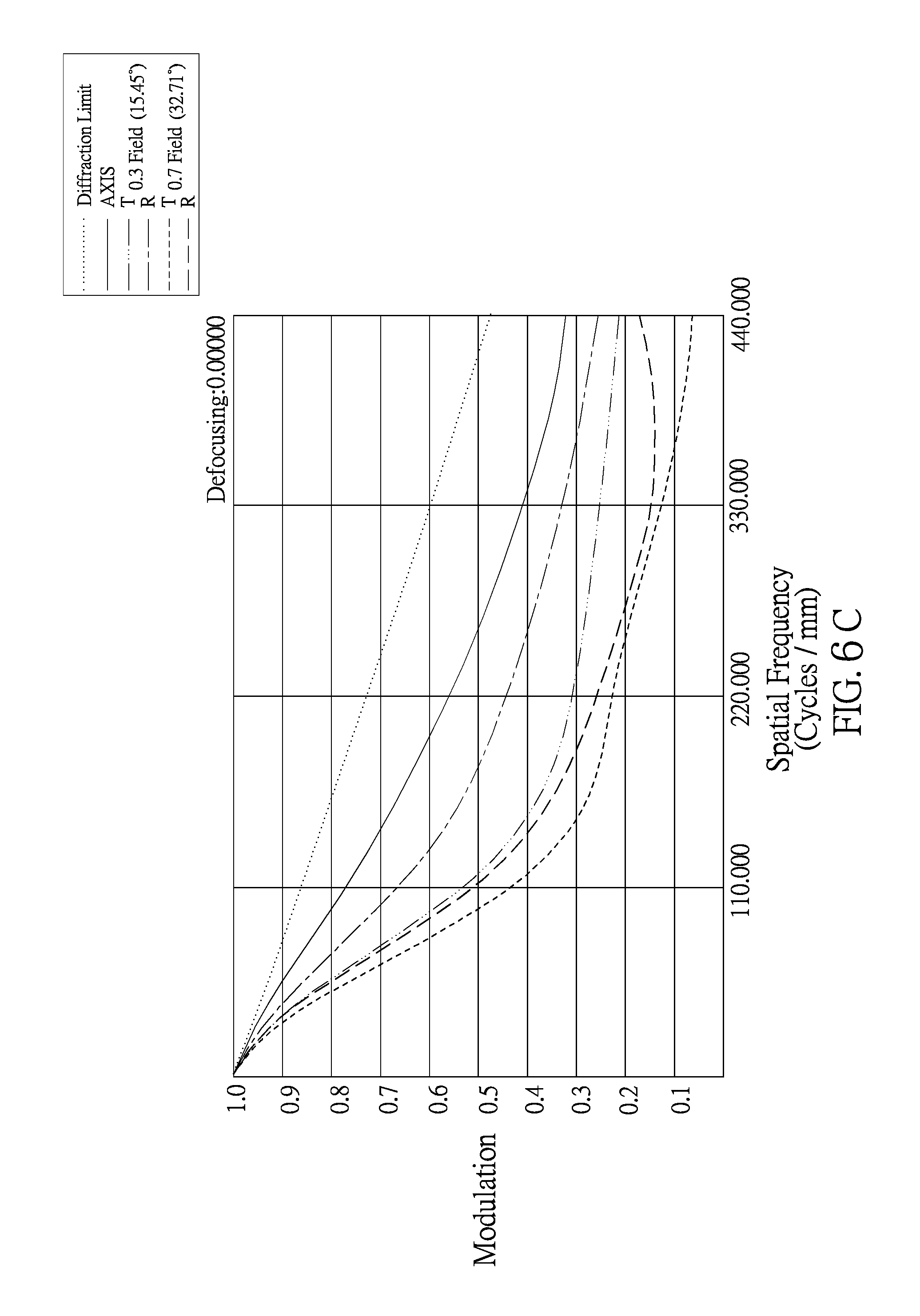
D00019

D00020
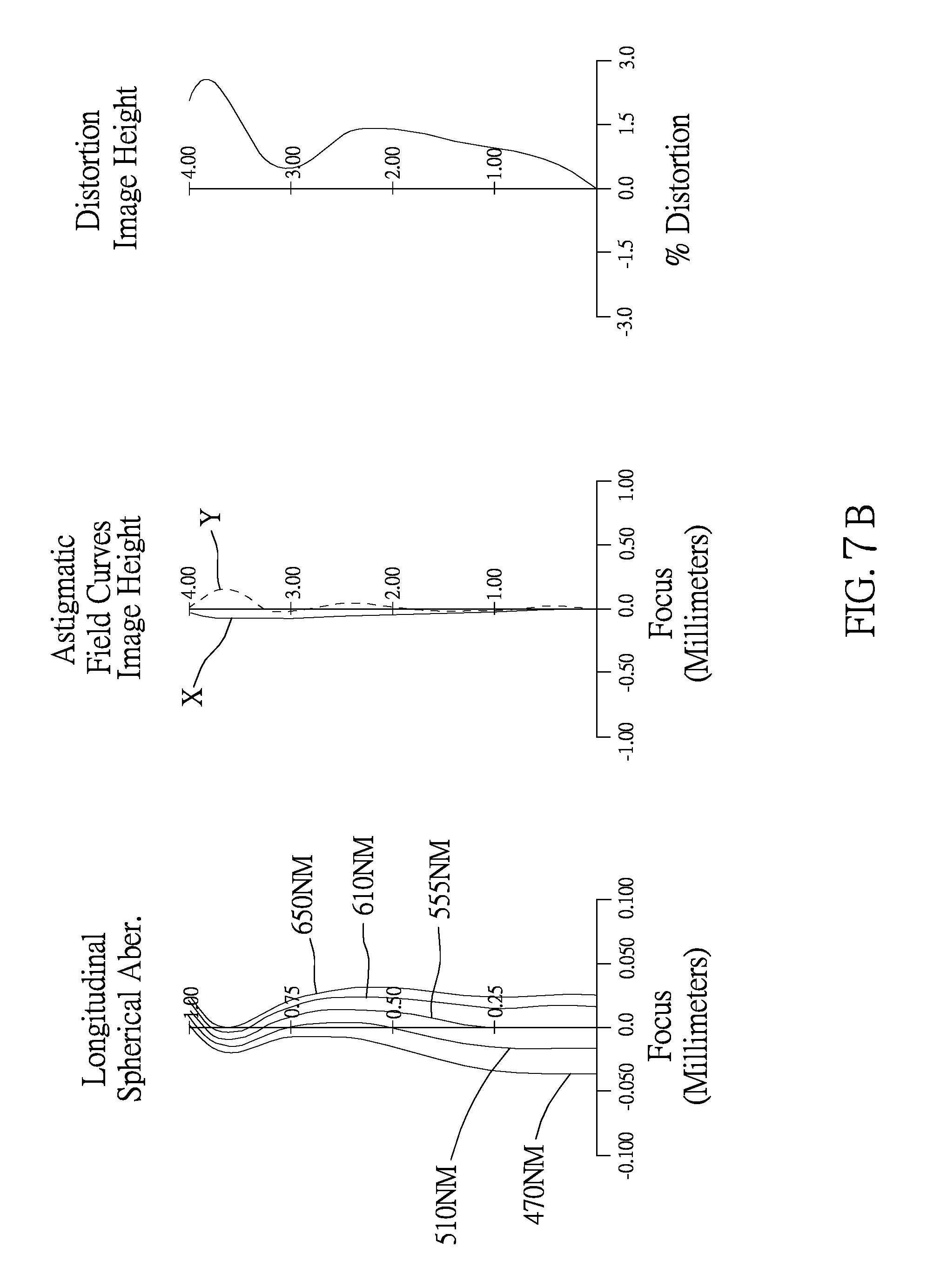
D00021

D00022
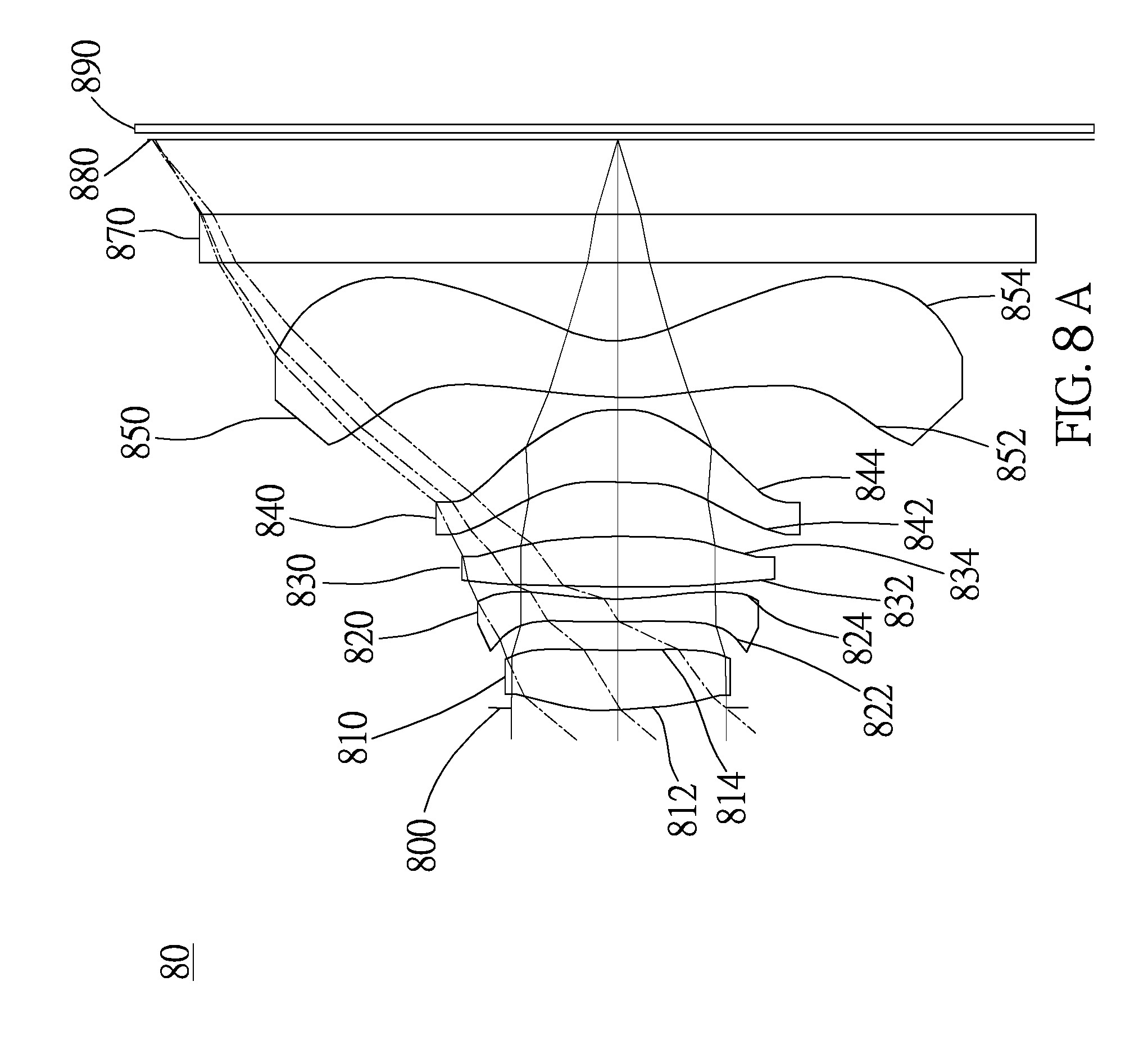
D00023

D00024
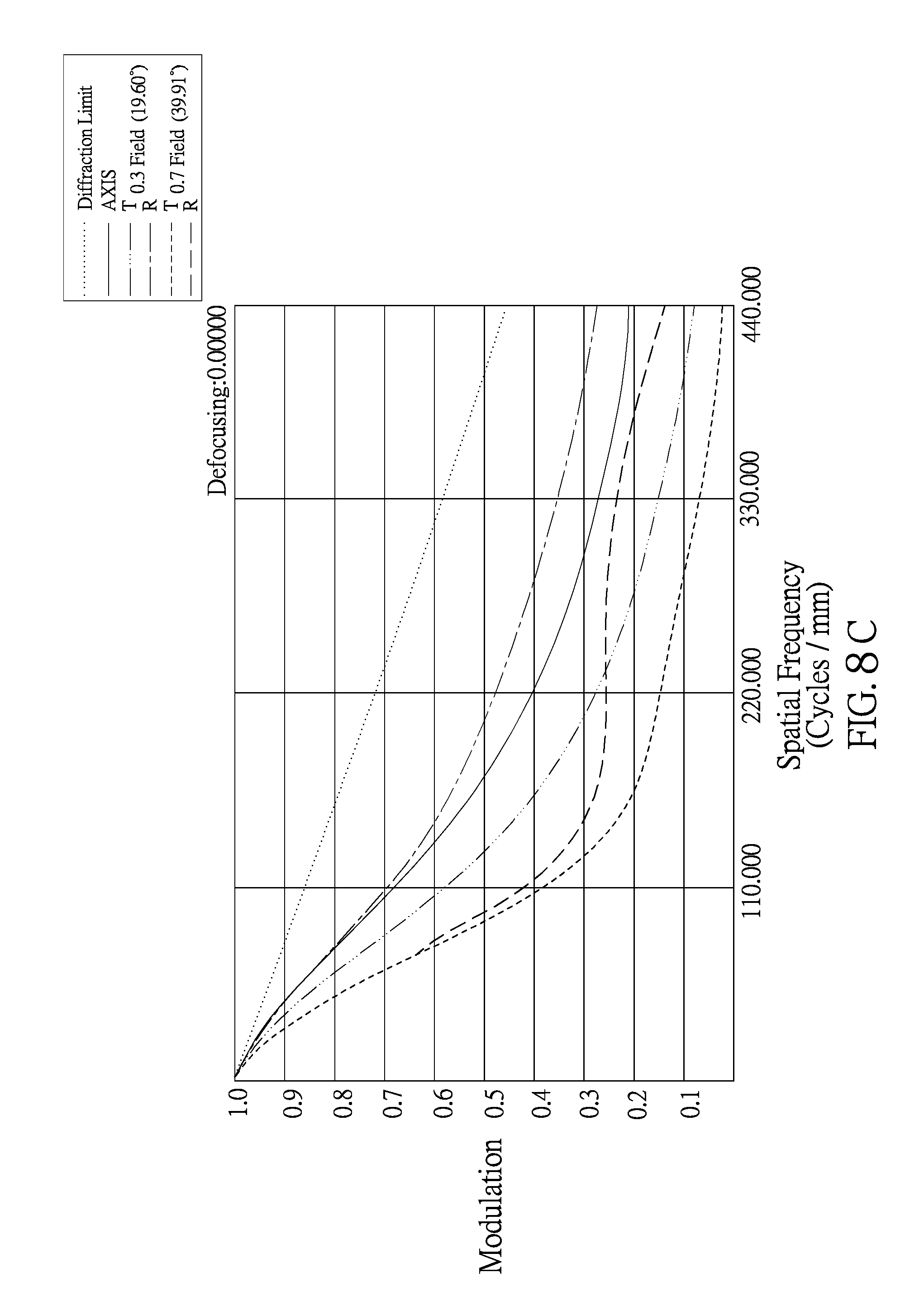
D00025

D00026

D00027

XML
uspto.report is an independent third-party trademark research tool that is not affiliated, endorsed, or sponsored by the United States Patent and Trademark Office (USPTO) or any other governmental organization. The information provided by uspto.report is based on publicly available data at the time of writing and is intended for informational purposes only.
While we strive to provide accurate and up-to-date information, we do not guarantee the accuracy, completeness, reliability, or suitability of the information displayed on this site. The use of this site is at your own risk. Any reliance you place on such information is therefore strictly at your own risk.
All official trademark data, including owner information, should be verified by visiting the official USPTO website at www.uspto.gov. This site is not intended to replace professional legal advice and should not be used as a substitute for consulting with a legal professional who is knowledgeable about trademark law.