Distal femoral knee prostheses
Earl , et al. O
U.S. patent number 10,433,966 [Application Number 15/424,382] was granted by the patent office on 2019-10-08 for distal femoral knee prostheses. This patent grant is currently assigned to Zimmer, Inc.. The grantee listed for this patent is Zimmer, Inc.. Invention is credited to Kim Bertin, Robert E Booth, Jr., Lawrence Dorr, Brian D. Earl, Abraham P Habegger, Aaron Hofmann, Sergio Romagnoli, Aaron Rosenberg.

View All Diagrams
| United States Patent | 10,433,966 |
| Earl , et al. | October 8, 2019 |
Distal femoral knee prostheses
Abstract
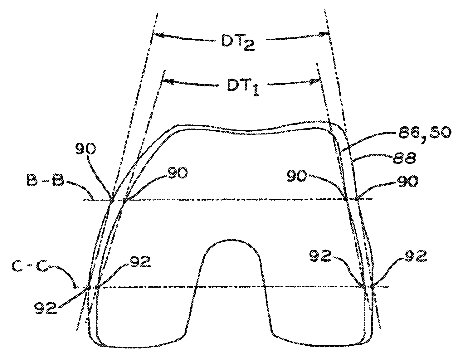
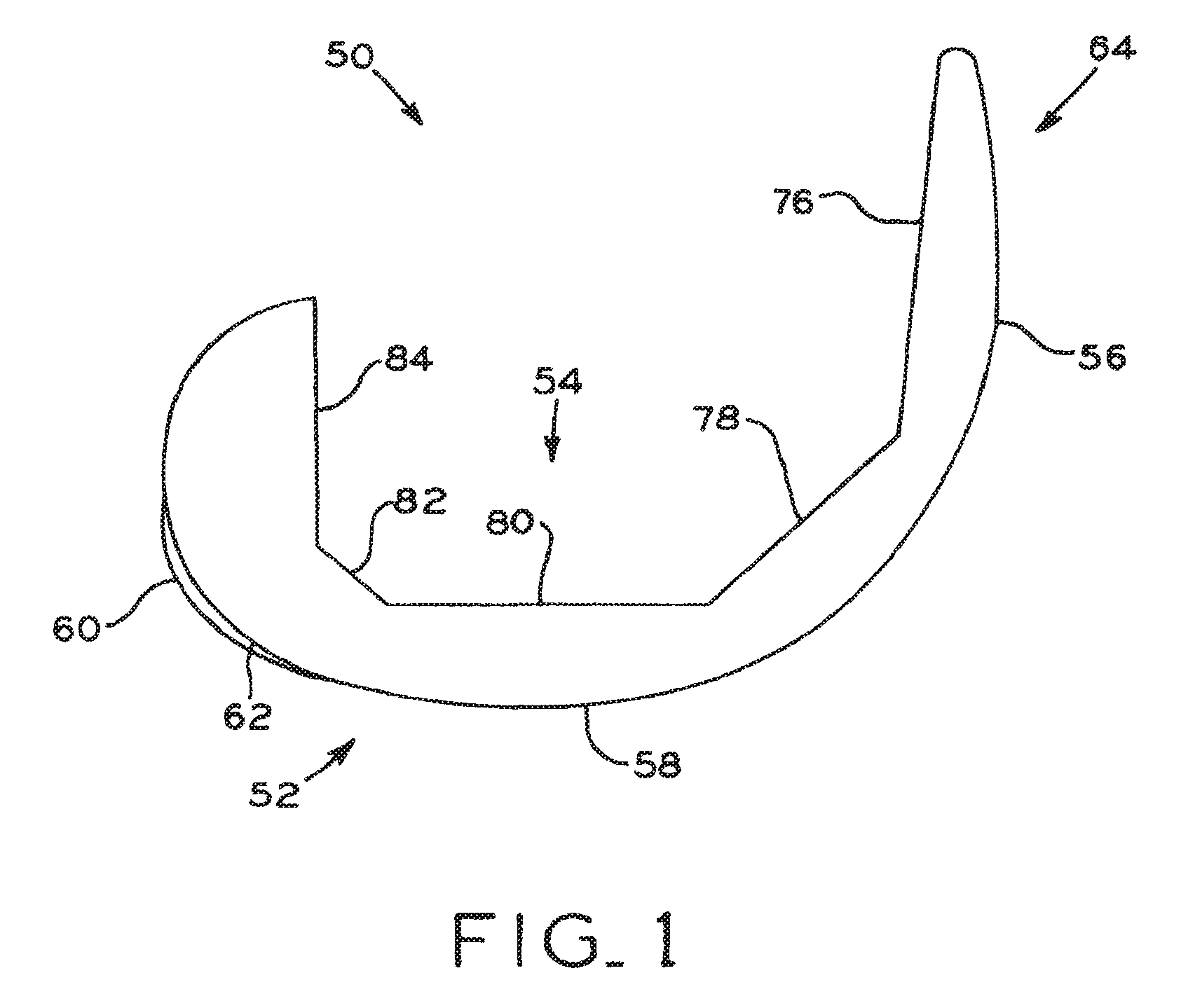
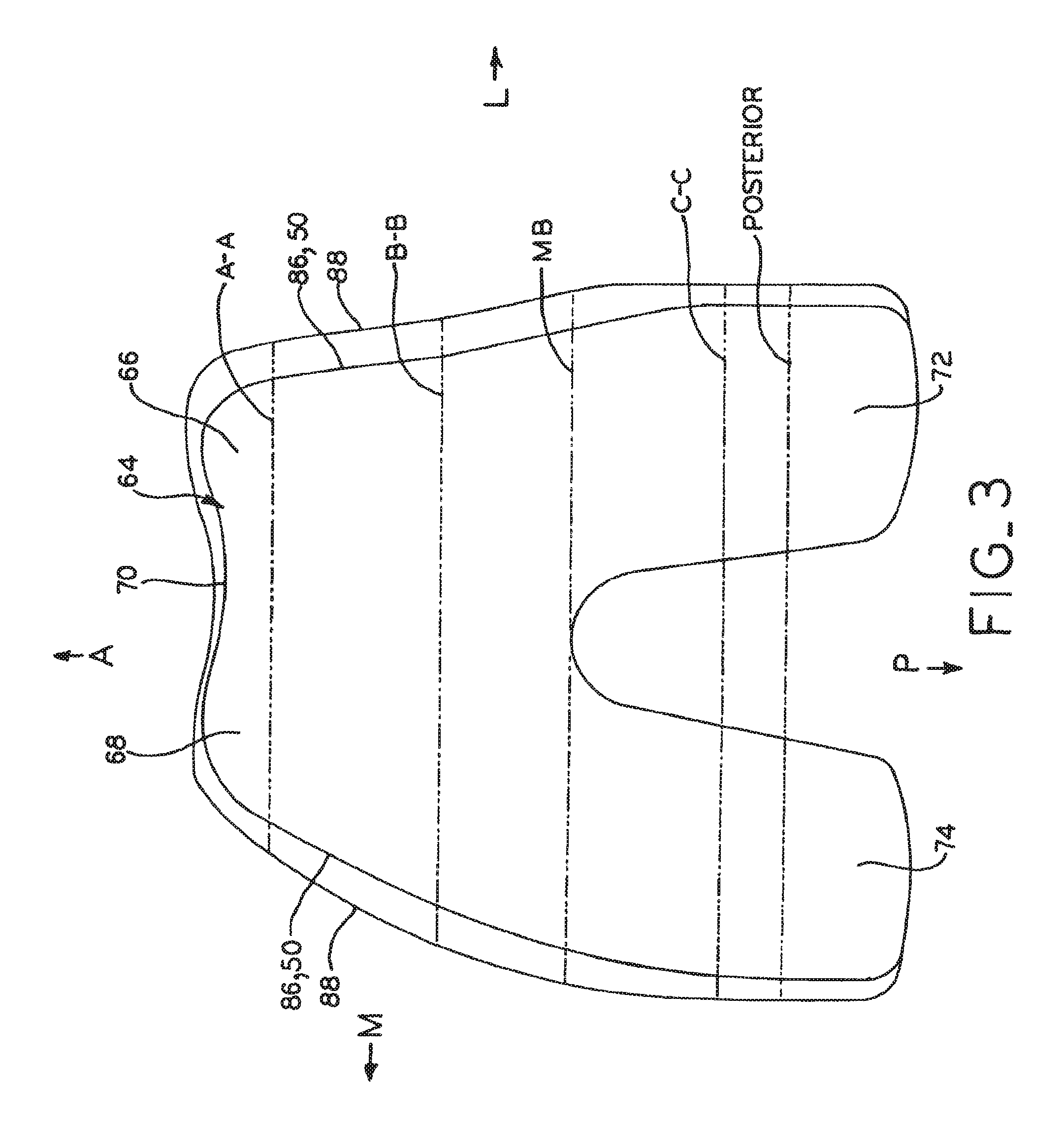
A set of distal femoral knee prostheses which are designed to be more narrow in medial/lateral dimensions with increasing anterior/posterior size than existing prostheses to more closely correspond to the physical anatomy of female patients. The prostheses are designed to have a substantially trapezoidal shape or profile when viewed distally which features a more pronounced narrowing of the medial/lateral dimensions beginning at the posterior end of the prostheses and progressing anteriorly to the anterior end of the prostheses. Additionally, the prostheses each include a reduced profile patellar sulcus and reduced profile anterior condyles to more closely conform to the anatomy of a resected femur, and also include sulcus tracking optimized to conform to female anatomy.
| Inventors: | Earl; Brian D. (South Bend, IN), Habegger; Abraham P (Warsaw, IN), Hofmann; Aaron (Salt Lake City, UT), Bertin; Kim (Bountiful, UT), Dorr; Lawrence (La Canada, CA), Booth, Jr.; Robert E (Philadelphia, PA), Rosenberg; Aaron (Deerfield, IL), Romagnoli; Sergio (Savona, IT) | ||||||||||
|---|---|---|---|---|---|---|---|---|---|---|---|
| Applicant: |
|
||||||||||
| Assignee: | Zimmer, Inc. (Warsaw,
IN) |
||||||||||
| Family ID: | 37912410 | ||||||||||
| Appl. No.: | 15/424,382 | ||||||||||
| Filed: | February 3, 2017 |
Prior Publication Data
| Document Identifier | Publication Date | |
|---|---|---|
| US 20170156872 A1 | Jun 8, 2017 | |
Related U.S. Patent Documents
| Application Number | Filing Date | Patent Number | Issue Date | ||
|---|---|---|---|---|---|
| 11611021 | Dec 14, 2006 | 9592127 | |||
| 60805933 | Jun 27, 2006 | ||||
| 60750613 | Dec 15, 2005 | ||||
| Current U.S. Class: | 1/1 |
| Current CPC Class: | A61F 2/3859 (20130101); A61F 2002/30667 (20130101); A61F 2002/30324 (20130101); A61F 2002/30616 (20130101) |
| Current International Class: | A61F 2/38 (20060101); A61F 2/30 (20060101) |
References Cited [Referenced By]
U.S. Patent Documents
| 4081866 | April 1978 | Upshaw et al. |
| 4340978 | July 1982 | Buechel et al. |
| 4662889 | May 1987 | Zichner et al. |
| 4888020 | December 1989 | Horber |
| 4944756 | July 1990 | Kenna |
| 4950298 | August 1990 | Gustilo et al. |
| 4959071 | September 1990 | Brown et al. |
| 5007933 | April 1991 | Sidebotham et al. |
| 5035700 | July 1991 | Kenna |
| 5061271 | October 1991 | Van Zile |
| 5133758 | July 1992 | Hollister |
| 5133760 | July 1992 | Petersen et al. |
| 5137536 | August 1992 | Koshino |
| 5226915 | July 1993 | Bertin |
| 5282861 | February 1994 | Kaplan |
| 5282869 | February 1994 | Miyajima et al. |
| 5326361 | July 1994 | Hollister |
| 5330532 | July 1994 | Ranawat |
| 5445642 | August 1995 | McNulty et al. |
| 5549686 | August 1996 | Johnson et al. |
| 5549688 | August 1996 | Ries et al. |
| 5609643 | March 1997 | Colleran et al. |
| 5681354 | October 1997 | Eckhoff |
| 5688279 | November 1997 | McNulty et al. |
| 5702460 | December 1997 | Carls et al. |
| 5728162 | March 1998 | Eckhoff |
| 5776201 | July 1998 | Colleran et al. |
| 5824105 | October 1998 | Ries et al. |
| 5871546 | February 1999 | Colleran et al. |
| 5879354 | March 1999 | Haines et al. |
| 5879393 | March 1999 | Whiteside et al. |
| 5935173 | August 1999 | Roger et al. |
| 6013103 | January 2000 | Kaufman et al. |
| 6039764 | March 2000 | Pottenger et al. |
| 6074424 | June 2000 | Perrone, Jr. et al. |
| 6106529 | August 2000 | Techiera |
| 6152960 | November 2000 | Pappas |
| 6197064 | March 2001 | Haines et al. |
| 6217619 | April 2001 | Keller |
| 6235060 | May 2001 | Kubein-Meesenburg et al. |
| 6264697 | July 2001 | Walker |
| 6325828 | December 2001 | Dennis et al. |
| 6364911 | April 2002 | Schmotzer et al. |
| 6540786 | April 2003 | Chibrac et al. |
| 6540787 | April 2003 | Biegun et al. |
| 6589283 | July 2003 | Metzger et al. |
| 6616696 | September 2003 | Merchant |
| 6699291 | March 2004 | Augoyard et al. |
| 6712856 | March 2004 | Carignan et al. |
| 6743258 | June 2004 | Keller |
| 6770099 | August 2004 | Andriacchi et al. |
| 6802865 | October 2004 | Biegun et al. |
| 6846329 | January 2005 | Mcminn |
| 6893467 | May 2005 | Bercovy |
| 7081137 | July 2006 | Servidio |
| 7297164 | November 2007 | Johnson et al. |
| 7306609 | December 2007 | Schmotzer et al. |
| 7364590 | April 2008 | Siebel |
| 7413577 | August 2008 | Servidio |
| 7442196 | October 2008 | Fisher et al. |
| 7465320 | December 2008 | Kito et al. |
| 7678152 | March 2010 | Suguro et al. |
| 7691150 | April 2010 | Cronin et al. |
| 7695520 | April 2010 | Metzger et al. |
| 7806897 | October 2010 | Bonutti |
| 8062377 | November 2011 | Haines |
| 8075626 | December 2011 | Dun |
| 8088167 | January 2012 | Haines |
| 8211181 | July 2012 | Walker |
| 8292964 | October 2012 | Walker |
| 8298288 | October 2012 | Walker |
| 8357202 | January 2013 | Heggendorn et al. |
| 8377141 | February 2013 | Mcminn |
| 8394147 | March 2013 | Otto et al. |
| 8409293 | April 2013 | Howard et al. |
| 8480753 | July 2013 | Collazo et al. |
| 8480754 | July 2013 | Bojarski et al. |
| 8500816 | August 2013 | Dees, Jr. et al. |
| 8551179 | October 2013 | Jones et al. |
| 8603101 | December 2013 | Claypool et al. |
| 8721732 | May 2014 | Samuelson et al. |
| 8911502 | December 2014 | Li et al. |
| 8932365 | January 2015 | Parisi et al. |
| 9060868 | June 2015 | Parisi et al. |
| 9173744 | November 2015 | Donno et al. |
| 9308095 | April 2016 | Parisi et al. |
| 9592127 | March 2017 | Earl et al. |
| 9839521 | December 2017 | Todd et al. |
| 9867708 | January 2018 | Donno et al. |
| 9956048 | May 2018 | Bojarski et al. |
| 10045850 | August 2018 | Parisi et al. |
| 10136997 | November 2018 | Yager |
| 2003/0153924 | August 2003 | Kana et al. |
| 2003/0158606 | August 2003 | Coon et al. |
| 2003/0225458 | December 2003 | Donkers et al. |
| 2004/0039450 | February 2004 | Griner et al. |
| 2004/0172137 | September 2004 | Blaylock et al. |
| 2004/0204766 | October 2004 | Siebel |
| 2004/0243245 | December 2004 | Plumet et al. |
| 2004/0249467 | December 2004 | Meyers et al. |
| 2005/0055102 | March 2005 | Tornier et al. |
| 2005/0102032 | May 2005 | Beynnon et al. |
| 2005/0107884 | May 2005 | Johnson et al. |
| 2005/0143832 | June 2005 | Carson |
| 2005/0177169 | August 2005 | Fisher et al. |
| 2005/0283249 | December 2005 | Carson |
| 2005/0283250 | December 2005 | Coon et al. |
| 2005/0283251 | December 2005 | Coon et al. |
| 2005/0283252 | December 2005 | Coon et al. |
| 2005/0283253 | December 2005 | Coon et al. |
| 2006/0028773 | February 2006 | Shimazawa et al. |
| 2006/0129246 | June 2006 | Steffensmeier |
| 2006/0142774 | June 2006 | Metzger |
| 2006/0224244 | October 2006 | Thomas et al. |
| 2006/0235541 | October 2006 | Hodorek |
| 2006/0235542 | October 2006 | Hodorek et al. |
| 2006/0241634 | October 2006 | Tuttle et al. |
| 2006/0265078 | November 2006 | Mcminn |
| 2006/0265080 | November 2006 | Mcminn |
| 2006/0287733 | December 2006 | Bonutti |
| 2007/0088444 | April 2007 | Hodorek et al. |
| 2007/0123984 | May 2007 | Hodorek |
| 2007/0135925 | June 2007 | Walker |
| 2007/0135926 | June 2007 | Walker |
| 2007/0150066 | June 2007 | McMinn |
| 2007/0179607 | August 2007 | Hodorek et al. |
| 2007/0233269 | October 2007 | Steines et al. |
| 2007/0260323 | November 2007 | Earl et al. |
| 2008/0058947 | March 2008 | Earl et al. |
| 2008/0058948 | March 2008 | Biegun et al. |
| 2008/0097615 | April 2008 | Lipman et al. |
| 2008/0097616 | April 2008 | Meyers et al. |
| 2008/0114463 | May 2008 | Auger et al. |
| 2008/0119940 | May 2008 | Otto et al. |
| 2008/0140212 | June 2008 | Metzger et al. |
| 2008/0188855 | August 2008 | Brown et al. |
| 2008/0188937 | August 2008 | Ribic |
| 2008/0188942 | August 2008 | Brown et al. |
| 2008/0243258 | October 2008 | Sancheti |
| 2008/0281428 | November 2008 | Meyers et al. |
| 2008/0288080 | November 2008 | Sancheti |
| 2009/0036992 | February 2009 | Tsakonas |
| 2009/0043395 | February 2009 | Hotokebuchi et al. |
| 2009/0062924 | March 2009 | Kito et al. |
| 2009/0105772 | April 2009 | Seebeck et al. |
| 2009/0132055 | May 2009 | Ferro |
| 2009/0149963 | June 2009 | Sekel |
| 2009/0222103 | September 2009 | Fitz et al. |
| 2009/0265011 | October 2009 | Mandell |
| 2009/0265013 | October 2009 | Mandell |
| 2009/0306786 | December 2009 | Samuelson |
| 2009/0306787 | December 2009 | Crabtree et al. |
| 2009/0319047 | December 2009 | Walker |
| 2009/0319048 | December 2009 | Shah et al. |
| 2009/0319049 | December 2009 | Shah et al. |
| 2009/0326663 | December 2009 | Dun |
| 2009/0326665 | December 2009 | Wyss et al. |
| 2009/0326666 | December 2009 | Wyss et al. |
| 2009/0326667 | December 2009 | Williams et al. |
| 2010/0036499 | February 2010 | Pinskerova |
| 2010/0036500 | February 2010 | Heldreth et al. |
| 2010/0042224 | February 2010 | Otto et al. |
| 2010/0161067 | June 2010 | Saleh et al. |
| 2010/0191298 | July 2010 | Earl et al. |
| 2010/0211179 | August 2010 | Angibaud et al. |
| 2010/0305708 | December 2010 | Lang |
| 2010/0329530 | December 2010 | Lang et al. |
| 2011/0022179 | January 2011 | Andriacchi et al. |
| 2011/0029091 | February 2011 | Bojarski et al. |
| 2011/0093083 | April 2011 | Earl et al. |
| 2011/0144760 | June 2011 | Wong et al. |
| 2011/0218541 | September 2011 | Bailey et al. |
| 2011/0307067 | December 2011 | Dees |
| 2012/0089234 | April 2012 | Mouillet et al. |
| 2012/0203350 | August 2012 | Hagen et al. |
| 2012/0310362 | December 2012 | Li et al. |
| 2012/0323334 | December 2012 | Jones et al. |
| 2012/0323335 | December 2012 | Parisi et al. |
| 2012/0323336 | December 2012 | Parisi et al. |
| 2012/0323337 | December 2012 | Parisi et al. |
| 2013/0006370 | January 2013 | Wogoman et al. |
| 2013/0006371 | January 2013 | Wogoman et al. |
| 2013/0006376 | January 2013 | Wogoman et al. |
| 2013/0006378 | January 2013 | Wogoman |
| 2013/0024001 | January 2013 | Wentorf et al. |
| 2013/0035765 | February 2013 | Dacus |
| 2013/0197653 | August 2013 | Hawkins et al. |
| 2013/0204380 | August 2013 | Mouillet et al. |
| 2013/0211532 | August 2013 | Samuelson et al. |
| 2013/0218284 | August 2013 | Eickmann et al. |
| 2013/0226305 | August 2013 | Donno et al. |
| 2013/0345821 | December 2013 | Jones et al. |
| 2014/0025081 | January 2014 | Lorio et al. |
| 2014/0128973 | May 2014 | Howard et al. |
| 2014/0142713 | May 2014 | Wright et al. |
| 2014/0228851 | August 2014 | Guloy, Jr. et al. |
| 2015/0045801 | February 2015 | Axelson, Jr. et al. |
| 2015/0081031 | March 2015 | Parisi et al. |
| 2015/0265410 | September 2015 | Parisi et al. |
| 2015/0374500 | December 2015 | Donno et al. |
| 2016/0030053 | February 2016 | Yager et al. |
| 2016/0220379 | August 2016 | Parisi et al. |
| 2016/0270856 | September 2016 | Park et al. |
| 2016/0278873 | September 2016 | Fisher et al. |
| 2017/0086982 | March 2017 | Yager |
| 2018/0064543 | March 2018 | Wright et al. |
| 2018/0092746 | April 2018 | Donno et al. |
| 2018/0125584 | May 2018 | Lang |
| 2018/0140440 | May 2018 | Jackson et al. |
| 2019/0046323 | February 2019 | Yager |
| 2006325787 | Oct 2013 | AU | |||
| 2641966 | Nov 2016 | CA | |||
| 101330883 | Dec 2008 | CN | |||
| 101522137 | Sep 2009 | CN | |||
| 101642394 | Feb 2010 | CN | |||
| 101658446 | Mar 2010 | CN | |||
| 101664347 | Mar 2010 | CN | |||
| 101669844 | Mar 2010 | CN | |||
| 101627930 | Oct 2010 | CN | |||
| 101879099 | Nov 2010 | CN | |||
| 101959475 | Jan 2011 | CN | |||
| 102006839 | Apr 2011 | CN | |||
| 102006840 | Apr 2011 | CN | |||
| 102076283 | May 2011 | CN | |||
| 101330883 | Mar 2013 | CN | |||
| 103118633 | May 2013 | CN | |||
| 103732186 | Apr 2014 | CN | |||
| 103732187 | Apr 2014 | CN | |||
| 103747762 | Apr 2014 | CN | |||
| 203657640 | Jun 2014 | CN | |||
| 103732188 | May 2016 | CN | |||
| 103732188 | May 2016 | CN | |||
| 103732186 | Sep 2016 | CN | |||
| 103747762 | Sep 2016 | CN | |||
| 106214293 | Dec 2016 | CN | |||
| 202007014128 | Jan 2008 | DE | |||
| 0303467 | Feb 1989 | EP | |||
| 0546726 | Jun 1993 | EP | |||
| 0376658 | Jun 1994 | EP | |||
| 0381352 | Jun 1994 | EP | |||
| 0722721 | Jul 1996 | EP | |||
| 0567705 | Jul 1997 | EP | |||
| 0993812 | Apr 2000 | EP | |||
| 1013232 | Jun 2000 | EP | |||
| 1285638 | Feb 2003 | EP | |||
| 1033117 | Jun 2004 | EP | |||
| 0975286 | Aug 2004 | EP | |||
| 1477142 | Nov 2004 | EP | |||
| 1477143 | Nov 2004 | EP | |||
| 1013232 | Oct 2005 | EP | |||
| 1285638 | Nov 2005 | EP | |||
| 1719478 | Nov 2006 | EP | |||
| 1722721 | Nov 2006 | EP | |||
| 1354571 | Jun 2007 | EP | |||
| 1862150 | Dec 2007 | EP | |||
| 2004099 | Dec 2008 | EP | |||
| 1867302 | Sep 2009 | EP | |||
| 2147660 | Jan 2010 | EP | |||
| 2158878 | Mar 2010 | EP | |||
| 1555962 | Feb 2011 | EP | |||
| 2324799 | May 2011 | EP | |||
| 2335654 | Jun 2011 | EP | |||
| 2720646 | Apr 2014 | EP | |||
| 2901996 | Dec 2007 | FR | |||
| 3008605 | Jan 2015 | FR | |||
| 64068255 | Mar 1989 | JP | |||
| 341694 | Sep 1991 | JP | |||
| 3267055 | Nov 1991 | JP | |||
| 0553501 | Mar 1993 | JP | |||
| 0568987 | Mar 1993 | JP | |||
| 9149908 | Jun 1997 | JP | |||
| 11504226 | Apr 1999 | JP | |||
| 11511347 | Oct 1999 | JP | |||
| 2003513706 | Apr 2003 | JP | |||
| 3469972 | Nov 2003 | JP | |||
| 3495161 | Feb 2004 | JP | |||
| 2004166802 | Jun 2004 | JP | |||
| 2005532089 | Oct 2005 | JP | |||
| 2008502393 | Jan 2008 | JP | |||
| 2008503327 | Feb 2008 | JP | |||
| 4077041 | Apr 2008 | JP | |||
| 2008523962 | Jul 2008 | JP | |||
| 2009519781 | May 2009 | JP | |||
| 4820547 | Nov 2011 | JP | |||
| 5571863 | Jul 2014 | JP | |||
| 2014522290 | Sep 2014 | JP | |||
| 2014522291 | Sep 2014 | JP | |||
| 2014522292 | Sep 2014 | JP | |||
| 2014522671 | Sep 2014 | JP | |||
| 2015164599 | Sep 2015 | JP | |||
| 5792898 | Oct 2015 | JP | |||
| WO-9014806 | Dec 1990 | WO | |||
| WO-9535074 | Dec 1995 | WO | |||
| WO-9603939 | Feb 1996 | WO | |||
| WO-0023010 | Apr 2000 | WO | |||
| WO-03094782 | Nov 2003 | WO | |||
| WO-2004016204 | Feb 2004 | WO | |||
| WO-2004084740 | Oct 2004 | WO | |||
| WO-2005037147 | Apr 2005 | WO | |||
| WO-2005051240 | Jun 2005 | WO | |||
| WO-2005122967 | Dec 2005 | WO | |||
| WO-2006002296 | Jan 2006 | WO | |||
| WO-2006058057 | Jun 2006 | WO | |||
| WO-2006069260 | Jun 2006 | WO | |||
| WO-2007007841 | Jan 2007 | WO | |||
| WO-2007053905 | May 2007 | WO | |||
| WO-2007054553 | May 2007 | WO | |||
| WO-2007070859 | Jun 2007 | WO | |||
| WO-2007109641 | Sep 2007 | WO | |||
| WO-2008054389 | May 2008 | WO | |||
| WO-2009088234 | Jul 2009 | WO | |||
| WO-2009088236 | Jul 2009 | WO | |||
| WO-2009088238 | Jul 2009 | WO | |||
| WO-2009105495 | Aug 2009 | WO | |||
| WO-2010008803 | Jan 2010 | WO | |||
| WO-2010075365 | Jul 2010 | WO | |||
| WO-2010108550 | Sep 2010 | WO | |||
| WO 2011072235 | Jun 2011 | WO | |||
| WO-2012031774 | Mar 2012 | WO | |||
| WO-2012112698 | Aug 2012 | WO | |||
| WO-2012173704 | Dec 2012 | WO | |||
| WO-2012173706 | Dec 2012 | WO | |||
| WO-2012173740 | Dec 2012 | WO | |||
| WO-2016153927 | Sep 2016 | WO | |||
| WO-2017058535 | Apr 2017 | WO | |||
Other References
|
"U.S. Appl. No. 15/092,107, Notice of Allowability dated May 10, 2018", 2 pgs. cited by applicant . "U.S. Appl. No. 15/092,107, Notice of Allowance dated Apr. 18, 2018", 8 pgs. cited by applicant . "U.S. Appl. No. 15/092,107, Response filed Jan. 9, 2018 to Restriction Requirement dated Nov. 17, 2017", 16 pgs. cited by applicant . "U.S. Appl. No. 15/267,826, Non Final Office Action dated Apr. 5, 2018", 8 pgs. cited by applicant . "U.S. Appl. No. 15/267,826, Response filed Feb. 22, 2018 to Restriction Requirement dated Dec. 27, 2017", 6 pgs. cited by applicant . "U.S. Appl. No. 15/267,826, Response filed Jun. 28, 2018 to Non Final Office Action dated Apr. 5, 2018", 9 pgs. cited by applicant . "U.S. Appl. No. 15/267,826, Restriction Requirement dated Dec. 27, 2017", 6 pgs. cited by applicant . "U.S. Appl. No. 15/835,144, Non Final Office Action dated Jul. 11, 2018", 9 pgs. cited by applicant . "U.S. Appl. No. 15/835,144, Preliminary Amendment filed Dec. 27, 2017", 7 pgs. cited by applicant . "Canadian Application Serial No. 2,839,433, Office Action dated Feb. 26, 2018", 4 pgs. cited by applicant . "Chinese Application Serial No. 201610697089.0, Office Action dated Feb. 7, 2018", (W/ English Translation), 27 pgs. cited by applicant . "Chinese Application Serial No. 201610697089.0, Office Action dated Jul. 16, 2018", w/ English translation, 10 pgs. cited by applicant . "Chinese Application Serial No. 201610697089.0, Response filed Apr. 10, 2018 to Office Action dated Feb. 7, 2018", 4 pgs. cited by applicant . "Chinese Application Serial No. 201610697089.0, Response filed Aug. 2, 2018 to Office Action dated Jul. 16, 2018", 11 pgs. cited by applicant . "International Application Serial No. PCT/US2016/052173, International Preliminary Report on Patentability dated Apr. 12, 2018", 8 pgs. cited by applicant . "Answer filed Dec. 1, 2010 of Zimmer, Inc and Zimmer Technology, Inc", W. Norman Scott and Giles R Scuderi vs. Zimmer, Inc and Zimmer Technology, Inc in the US District Court of Delaware in Case No. 10-772-GMS, (Dec. 1, 2010), 36 pgs. cited by applicant . "U.S. Appl. No. 11/611,021, Advisory Action dated Jan. 22, 2016", 3 pgs. cited by applicant . "U.S. Appl. No. 11/611,021, Examiner Interview Summary dated Jun. 30, 2016", 3 pgs. cited by applicant . "U.S. Appl. No. 11/611,021, Final Office Action dated Mar. 10, 2011", 7 pgs. cited by applicant . "U.S. Appl. No. 11/611,021, Final Office Action dated Sep. 25, 2014", 9 pgs. cited by applicant . "U.S. Appl. No. 11/611,021, Final Office Action dated Nov. 6, 2015", 11 pgs. cited by applicant . "U.S. Appl. No. 11/611,021, Non Final Office Action dated Jan. 17, 2014", 11 pgs. cited by applicant . "U.S. Appl. No. 11/611,021, Non Final Office Action dated Apr. 8, 2016", 11 pgs. cited by applicant . "U.S. Appl. No. 11/611,021, Non Final Office Action dated Jun. 17, 2015", 12 pgs. cited by applicant . "U.S. Appl. No. 11/611,021, Non Final Office Action dated Jul. 21, 2010", 8 pgs. cited by applicant . "U.S. Appl. No. 11/611,021, Non-Final Office Action dated Dec. 7, 2009", 4 pgs. cited by applicant . "U.S. Appl. No. 11/611,021, Notice of Allowance dated Nov. 4, 2016", 10 pgs. cited by applicant . "U.S. Appl. No. 11/611,021, Preliminary Amendment dated Oct. 26, 2007", 7 pgs. cited by applicant . "U.S. Appl. No. 11/611,021, Response filed Jan. 4, 2016 to Final Office Action dated Nov. 6, 2015", 12 pgs. cited by applicant . "U.S. Appl. No. 11/611,021, Response filed Feb. 24, 2015 to Final Office Action dated Sep. 25, 2014", 16 pgs. cited by applicant . "U.S. Appl. No. 11/611,021, Response filed May 3, 2010 to Non Final Office Action dated Dec. 7, 2009", 14 pgs. cited by applicant . "U.S. Appl. No. 11/611,021, Response filed Jun. 6, 2011 Final Office Action dated Mar. 10, 2011", 8 pgs. cited by applicant . "U.S. Appl. No. 11/611,021, Response filed Jul. 15, 2014 to Non-Final Office Action dated Jan. 17, 2014", 19 pgs. cited by applicant . "U.S. Appl. No. 11/611,021, Response filed Aug. 5, 2016 to Non Final Office Action dated Apr. 8, 2016", 18 pgs. cited by applicant . "U.S. Appl. No. 11/611,021, Response filed Aug. 25, 2015 to Non Final Office Action dated Jun. 17, 2015", 14 pgs. cited by applicant . "U.S. Appl. No. 11/611,021, Response filed Dec. 21, 2010 to Non Final Office Action dated Jul. 21, 2010", 14 pgs. cited by applicant . "U.S. Appl. No. 11/780,248, Non Final Office Action dated Feb. 4, 2010", 4 pgs. cited by applicant . "U.S. Appl. No. 11/780,248, Non Final Office Action dated Jul. 21, 2010", 11 pgs. cited by applicant . "U.S. Appl. No. 11/780,248, Response filed May 3, 2010 to Non Final Office Action dated Feb. 4, 2010", 13 pgs. cited by applicant . "U.S. Appl. No. 12/974,018, Appeal Brief filed Feb. 20, 2015", 24 pgs. cited by applicant . "U.S. Appl. No. 12/974,018, Final Office Action dated Apr. 13, 2012", 11 pgs. cited by applicant . "U.S. Appl. No. 12/974,018, Final Office Action dated Oct. 10, 2014", 12 pgs. cited by applicant . "U.S. Appl. No. 12/974,018, Non Final Office Action dated Apr. 4, 2014", 11 pgs. cited by applicant . "U.S. Appl. No. 12/974,018, Non Final Office Action dated Nov. 10, 2011", 5 pgs. cited by applicant . "U.S. Appl. No. 12/974,018, Preliminary Amendment filed Dec. 21, 2010", 4 pgs. cited by applicant . "U.S. Appl. No. 12/974,018, Response filed Mar. 8, 2012 to Non Final Office Action dated Nov. 10, 2011", 12 pgs. cited by applicant . "U.S. Appl. No. 12/974,018, Response filed Jul. 30, 2014 to Non-Final Office Action dated Apr. 4, 2014", 15 pgs. cited by applicant . "U.S. Appl. No. 12/974,018, Response filed Oct. 12, 2012 to Final Office Action dated Apr. 13, 2012", 16 pgs. cited by applicant . "U.S. Appl. No. 13/161,624, Notice of Allowance dated Mar. 12, 2013", 11 pgs. cited by applicant . "U.S. Appl. No. 13/161,624, Response filed Feb. 26, 2013 to Restriction Requirement dated Sep. 26, 2012", 9 pgs. cited by applicant . "U.S. Appl. No. 13/161,624, Restriction Requirement dated Sep. 26, 2012", 8 pgs. cited by applicant . "U.S. Appl. No. 13/459,060, Advisory Action dated Jun. 8, 2015", 3 pgs. cited by applicant . "U.S. Appl. No. 13/459,060, Final Office Action dated Apr. 1, 2015", 11 pgs. cited by applicant . "U.S. Appl. No. 13/459,060, Non Final Office Action dated Mar. 14, 2014", 8 pgs. cited by applicant . "U.S. Appl. No. 13/459,060, Non Final Office Action dated Oct. 9, 2014", 11 pgs. cited by applicant . "U.S. Appl. No. 13/459,060, Notice of Allowance dated Dec. 7, 2015", 7 pgs. cited by applicant . "U.S. Appl. No. 13/459,060, Preliminary Amendment filed Apr. 27, 2012", 6 pgs. cited by applicant . "U.S. Appl. No. 13/459,060, PTO Response to Rule 312 Communication dated Mar. 3, 2016", 2 pgs. cited by applicant . "U.S. Appl. No. 13/459,060, Response filed Jan. 3, 2014 to Restriction Requirement dated Nov. 4, 2013", 25 pgs. cited by applicant . "U.S. Appl. No. 13/459,060, Response filed Feb. 18, 2015 to Non-Final Office Action dated Oct. 9, 2014", 23 pgs. cited by applicant . "U.S. Appl. No. 13/459,060, Response filed May 28, 2015 to Final Office Action dated Apr. 1, 2015", 21 pgs. cited by applicant . "U.S. Appl. No. 13/459,060, Response filed Jul. 14, 2015 to Non-Final Office Action dated Mar. 14, 2014", 30 pgs. cited by applicant . "U.S. Appl. No. 13/459,060, Restriction Requirement dated Nov. 4, 2013", 6 pgs. cited by applicant . "U.S. Appl. No. 13/459,061, Advisory Action dated Sep. 30, 2014", 3 pgs. cited by applicant . "U.S. Appl. No. 13/459,061, Final Office Action dated Jul. 23, 2014", 10 pgs. cited by applicant . "U.S. Appl. No. 13/459,061, Non Final Office Action dated Mar. 26, 2014", 8 pgs. cited by applicant . "U.S. Appl. No. 13/459,061, Non Final Office Action dated Nov. 10, 2014", 9 pgs. cited by applicant . "U.S. Appl. No. 13/459,061, Notice of Allowance dated Feb. 27, 2015", 8 pgs. cited by applicant . "U.S. Appl. No. 13/459,061, Preliminary Amendment filed Apr. 27, 2012", 6 pgs. cited by applicant . "U.S. Appl. No. 13/459,061, Response filed Jan. 10, 2014 to Restriction Requirement dated Nov. 12, 2013", 8 pgs. cited by applicant . "U.S. Appl. No. 13/459,061, Response filed Feb. 10, 2015 to Non Final Office Action dated Nov. 10, 2014", 12 pgs. cited by applicant . "U.S. Appl. No. 13/459,061, Response filed Jun. 25, 2014 to Non Final Office Action dated Mar. 26, 2014", 11 pgs. cited by applicant . "U.S. Appl. No. 13/459,061, Response filed Sep. 19, 2014 to Final Office Action dated Jul. 23, 2014", 9 pgs. cited by applicant . "U.S. Appl. No. 13/459,061, Restriction Requirement dated Nov. 12, 2013", 5 pgs. cited by applicant . "U.S. Appl. No. 13/459,064, Final Office Action dated Jun. 13, 2014", 10 pgs. cited by applicant . "U.S. Appl. No. 13/459,064, Non Final Office Action dated Mar. 6, 2014", 8 pgs. cited by applicant . "U.S. Appl. No. 13/459,064, Notice of Allowance dated Aug. 28, 2014", 8 pgs. cited by applicant . "U.S. Appl. No. 13/459,064, Preliminary Amendment filed Apr. 27, 2012", 6 pgs. cited by applicant . "U.S. Appl. No. 13/459,064, PTO Response to Rule 312 Communication dated Dec. 15, 2014", 2 pgs. cited by applicant . "U.S. Appl. No. 13/459,064, Response filed Jan. 27, 2014 to Restriction Requirement dated Nov. 25, 2013", 13 pgs. cited by applicant . "U.S. Appl. No. 13/459,064, Response filed Jun. 3, 2014 to Non-Final Office action dated Mar. 6, 2014", 13 pgs. cited by applicant . "U.S. Appl. No. 13/459,064, Response filed Aug. 13, 2014 to Final Office Action dated Jun. 13, 2014", 13 pgs. cited by applicant . "U.S. Appl. No. 13/459,064, Restriction Requirement dated Nov. 25, 2013", 5 pgs. cited by applicant . "U.S. Appl. No. 13/819,528, Advisory Action dated Apr. 14, 2015", 3 pgs. cited by applicant . "U.S. Appl. No. 13/819,528, Final Office Action dated Feb. 5, 2015", 15 pgs. cited by applicant . "U.S. Appl. No. 13/819,528, Non Final Office Action dated Aug. 12, 2014", 10 pgs. cited by applicant . "U.S. Appl. No. 13/819,528, Non Final Office Action dated Dec. 6, 2013", 15 pgs. cited by applicant . "U.S. Appl. No. 13/819,528, Notice of Allowance dated Jun. 22, 2015", 7 pgs. cited by applicant . "U.S. Appl. No. 13/819,528, Preliminary Amendment filed Feb. 27, 2013", 9 pgs. cited by applicant . "U.S. Appl. No. 13/819,528, Response filed Jan. 12, 2015 to Non Final Office Action dated Aug. 12, 2014", 13 pgs. cited by applicant . "U.S. Appl. No. 13/819,528, Response filed Apr. 2, 2015 to Final Office Action dated Feb. 5, 2015", 12 pgs. cited by applicant . "U.S. Appl. No. 13/819,528, Response filed Apr. 29, 2015 to Advisory Action dated Apr. 14, 2015", 13 pgs. cited by applicant . "U.S. Appl. No. 13/819,528, Response filed May 22, 2014 to Non Final Office Action dated Dec. 6, 2013", 15 pgs. cited by applicant . "U.S. Appl. No. 13/819,528, Supplemental Preliminary Amendment filed Jul. 11, 2013", 6 pgs. cited by applicant . "U.S. Appl. No. 14/014,737, Advisory Action dated Oct. 23, 2014", 3 pgs. cited by applicant . "U.S. Appl. No. 14/014,737, Appeal Brief filed Feb. 12, 2015", 12 pgs. cited by applicant . "U.S. Appl. No. 14/014,737, Final Office Action dated Aug. 15, 2014", 5 pgs. cited by applicant . "U.S. Appl. No. 14/014,737, Non Final Office Action dated May 6, 2014", 6 pgs. cited by applicant . "U.S. Appl. No. 14/014,737, Pre-Appeal Brief Request filed Nov. 14, 2014", 4 pgs. cited by applicant . "U.S. Appl. No. 14/014,737, Preliminary Amendment filed Nov. 6, 2013", 7 pgs. cited by applicant . "U.S. Appl. No. 14/014,737, Response filed Aug. 6, 2014 to Non-Final Office Action dated May 6, 2014", 8 pgs. cited by applicant . "U.S. Appl. No. 14/014,737, Response filed Oct. 15, 2014 to Final Office Action dated Aug. 15, 2014", 8 pgs. cited by applicant . "U.S. Appl. No. 14/525,595, filed Oct. 28, 2014", 40 pgs. cited by applicant . "U.S. Appl. No. 14/553,034, Final Office Action dated Sep. 27, 2016", 7 pgs. cited by applicant . "U.S. Appl. No. 14/553,034, Non Final Office Action dated Apr. 20, 2016", 15 pgs. cited by applicant . "U.S. Appl. No. 14/553,034, Notice of Allowance dated Dec. 21, 2016", 5 pgs. cited by applicant . "U.S. Appl. No. 14/553,034, Preliminary Amendment filed Mar. 13, 2015", 10 pgs. cited by applicant . "U.S. Appl. No. 14/553,034, Response filed Aug. 22, 2016 to Non Final Office Action dated Apr. 20, 2016", 10 pgs. cited by applicant . "U.S. Appl. No. 14/553,034, Response filed Nov. 21, 2016 to Final Office Action dated Sep. 27, 2016", 9 pgs. cited by applicant . "U.S. Appl. No. 14/731,013, Preliminary Amendment dated Jun. 4, 2015", 7 pgs. cited by applicant . "U.S. Appl. No. 14/731,013, Supplemental Preliminary Amendment filed Jun. 18, 2015", 5 pgs. cited by applicant . "U.S. Appl. No. 14/845,522, Final Office Action dated Oct. 18, 2016", 10 pgs. cited by applicant . "U.S. Appl. No. 14/845,522, Non Final Office Action dated Feb. 8, 2017", 11 pgs. cited by applicant . "U.S. Appl. No. 14/845,522, Non Final Office Action dated Jun. 1, 2016", 11 pgs. cited by applicant . "U.S. Appl. No. 14/845,522, Preliminary Amendment filed Sep. 24, 2015", 7 pgs. cited by applicant . "U.S. Appl. No. 14/845,522, Response filed Sep. 1, 2016 to Non Final Office Action dated Jun. 1, 2016", 14 pgs. cited by applicant . "U.S. Appl. No. 14/845,622; Response filed Jan. 11, 2017 to Final Office Action dated Oct. 18, 2016", 12 pgs. cited by applicant . "U.S. Appl. No. 15/092,107, Preliminary Amendment filed Apr. 7, 2016", 11 pgs. cited by applicant . "U.S. Appl. No. 61/381,803, filed Sep. 10, 2010", 23 pgs. cited by applicant . "Australian Application Serial No. 2006325787, Office Action dated Mar. 14, 2012", 2 pgs. cited by applicant . "Australian Application Serial No. 2006325787, Office Action dated Nov. 14, 2011", 2 pgs. cited by applicant . "Australian Application Serial No. 2006325787, Response filed May 3, 2013 to Office Action dated Mar. 14, 2012", 10 pgs. cited by applicant . "Australian Application Serial No. 2006325787, Response filed Feb. 21, 2012 to Office Action dated Nov. 14, 2011", 34 pgs. cited by applicant . "Australian Application Serial No. 2012271153, Amendment filed Jan. 16, 2014", 13 pgs. cited by applicant . "Australian Application Serial No. 2012271186, First Examiner Report dated Dec. 15, 2015", 3 pgs. cited by applicant . "Australian Application Serial No. 2012271186, Response filed Jun. 24, 2016 to First Examiner Report dated Dec. 15, 2015", 14 pgs. cited by applicant . "Australian Application Serial No. 2012271186, Subsequent Examiners Report dated Aug. 2, 2016", 3 pgs. cited by applicant . "Australian Application Serial No. 2012271243, Office Action dated Apr. 1, 2015", 2 pgs. cited by applicant . "Australian Application Serial No. 2012271243, Response filed Apr. 8, 2015 to Office Action dated Apr. 1, 2015", 4 pgs. cited by applicant . "Australian Application Serial No. 2012271243, Response filed Apr. 15, 2015 to Office Action dated Apr. 13, 2015", 1 pg. cited by applicant . "Australian Application Serial No. 2012271243, Subsequent Examiners Report dated Apr. 13, 2015", 2 pgs. cited by applicant . "Australian Application Serial No. 2012271244, First Examiner Report dated Dec. 15, 2015", 3 pgs. cited by applicant . "Australian Application Serial No. 2012271244, Response filed Jun. 24, 2016 to First Examiner Report dated Dec. 15, 2015", 13 pgs. cited by applicant . "Australian Application Serial No. 2013245552, First Examiner Report dated Mar. 30, 2016", 4 pgs. cited by applicant . "Canadian Application Serial No. 2,641,966, Office Action dated Feb. 6, 2014", 2 pgs. cited by applicant . "Canadian Application Serial No. 2,641,966, Office Action dated Jul. 16, 2013", 2 pgs. cited by applicant . "Canadian Application Serial No. 2,641,966, Office Action dated Aug. 25, 2014", 2 pgs. cited by applicant . "Canadian Application Serial No. 2,641,966, Office Action dated Sep. 4, 2015", 4 pgs. cited by applicant . "Canadian Application Serial No. 2,641,966, Response filed Jan. 15, 2014 to Office Action dated Jul. 16, 2013", 6 pgs. cited by applicant . "Canadian Application Serial No. 2,641,966, Response filed Feb. 25, 2015 to Office Action dated Aug. 25, 2014", 4 pgs. cited by applicant . "Canadian Application Serial No. 2,641,966, Response filed Aug. 6, 2014 to Office Action dated Feb. 6, 2014", 3 pgs. cited by applicant . "Canadian Application Serial No. 294408, Voluntary Amendment filed Sep. 18, 2015", 6 pgs. cited by applicant . "Chinese Application Serial No. 200680046893, Office Action dated Aug. 3, 2012", (W/ English Translation), 8 pgs. cited by applicant . "Chinese Application Serial No. 200680046893, Office Action dated Aug. 10, 2010", (W/ English Translation), 22 pgs. cited by applicant . "Chinese Application Serial No. 200680046893, Office Action dated Dec. 6, 2011", (W/ English Translation), 5 pgs. cited by applicant . "Chinese Application Serial No. 200680046893, Response filed Jan. 23, 2012 to Office Action dated Dec. 6, 2011", (W/ English Translation), 11 pgs. cited by applicant . "Chinese Application Serial No. 200680046893.7, Response filed Oct. 17, 2012 to Office Action dated Aug. 3, 2012", (W/ English Translation), 8 pgs. cited by applicant . "Chinese Application Serial No. 201280039703.4, Office Action dated Mar. 30, 2015", (W/ English Translation), 2 pgs. cited by applicant . "Chinese Application Serial No. 201280039703.4, Office Action dated May 10, 2016", No English Translation, 3 pgs. cited by applicant . "Chinese Application Serial No. 201280039703.4, Office Action dated May 28, 201505-28-15", (W/ English Translation), 12 pgs. cited by applicant . "Chinese Application Serial No. 201280039703.4, Office Action dated Dec. 3, 2015", No English Translation, 3 pgs. cited by applicant . "Chinese Application Serial No. 201280039703.4, Response filed Feb. 1, 2016 to Office Action dated Dec. 3, 2015", No English Translation, 12 pgs. cited by applicant . "Chinese Application Serial No. 201280039703.4, Response filed May 31, 2016 to Office Action dated May 10, 2016", (W/ English Translation), 34 pgs. cited by applicant . "Chinese Application Serial No. 201280039703.4, Response filed Sep. 7, 2015 to Office Action dated May 28, 2015", (W/ English Translation), 72 pgs. cited by applicant . "Chinese Application Serial No. 201280039705.3, Office Action dated Mar. 20, 2015", (W/ English Translation), 15 pgs. cited by applicant . "Chinese Application Serial No. 201280039705.3, Response filed Aug. 6, 2015 to Office Action dated Mar. 20, 2015", (W/ English translation of claims), 11 pgs. cited by applicant . "Chinese Application Serial No. 201280039705.3, Voluntary Amendment filed Jul. 22, 2014", No English Translation, 5 pgs. cited by applicant . "Chinese Application Serial No. 201280039706.8, Office Action dated Feb. 26, 2016", W/ English Translation, 4 pgs. cited by applicant . "Chinese Application Serial No. 201280039706.8, Office Action dated May 19, 2015", (W/ English Translation), 14 pgs. cited by applicant . "Chinese Application Serial No. 201280039706.8, Response filed May 11, 2016 to Office Action dated Feb. 26, 2016", W/ English Translation of Claims, 9 pgs. cited by applicant . "Chinese Application Serial No. 201280039706.8, Response filed Nov. 16, 2015 to Office Action dated May 19, 2015", W/ English Translation of Claims, 16 pgs. cited by applicant . "Chinese Application Serial No. 201280039714.2, Office Action dated May 4, 2015", (W/ English Translation), 19 pgs. cited by applicant . "Chinese Application Serial No. 201280039714.2, Office Action dated Dec. 3, 2015", (W/ English Translation), 7 pgs. cited by applicant . "Chinese Application Serial No. 201280039714.2, Response filed Feb. 1, 2016 to Office Action dated Dec. 3, 2015", No English Translation, 5 pgs. cited by applicant . "Chinese Application Serial No. 201280039714.2, Response filed Sep. 18, 2015 to Office Action dated May 4, 2015", (W/ English Translation of Claims), 9 pgs. cited by applicant . "Complaint of W. Norman Scot and Giles R. Scuderi filed Sep. 9, 2010", W. Norman Scott and Giles R Scuderi vs. Zimmer, Inc and Zimmer Technology, Inc in the US District Court of Delaware in Case No. 10-772-GMS, (Sep. 9, 2010), 24 pgs. cited by applicant . "European Application Serial No. 06840269.2, Decision to Grant dated Feb. 18, 2016", 3 pgs. cited by applicant . "European Application Serial No. 06840269.2, Examination Notification Art. 94(3) dated Jan. 24, 2014", 6 pgs. cited by applicant . "European Application Serial No. 06840269.2, Examination Notification Art. 94(3) dated Nov. 12, 2014", 4 pgs. cited by applicant . "European Application Serial No. 06840269.2, Office Action dated Sep. 8, 2015", 67 pgs. cited by applicant . "European Application Serial No. 06840269.2, Response filed Mar. 23, 2015 to Examination Notification Art. 94(3) dated Nov. 12, 2014", 10 pgs. cited by applicant . "European Application Serial No. 06840269.2, Response filed Aug. 4, 2014 to Examination Notification Art. 94(3) dated Jan. 24, 2014", 10 pgs. cited by applicant . "European Application Serial No. 12720354.5, Decision of Grant dated Dec. 3, 2015", 3 pgs. cited by applicant . "European Application Serial No. 12720354.5, Examination Notification Art. 94(3) dated Oct. 22, 2014", 4 pgs. cited by applicant . "European Application Serial No. 12720354.5, Office Action dated Jun. 17, 2015", 96 pgs. cited by applicant . "European Application Serial No. 12720354.5, Response filed Aug. 21, 2014 to Communication pursuant to Rules 161(2) and 162 EPC dated Feb. 14, 2014", 17 pgs. cited by applicant . "European Application Serial No. 12720354.5, Response filed Dec. 24, 2014 to Examination Notification Art 94(3) dated Oct. 22, 2014", 13 pgs. cited by applicant . "European Application Serial No. 12722967.2, Examination Notification Art. 94(3) dated Oct. 22, 2014", 4 pgs. cited by applicant . "European Application Serial No. 12724484.6, Communication Pursuant to Article 94(3) EPC dated May 2, 2016", 5 pgs. cited by applicant . "European Application Serial No. 12724484.6, Examination Notification Art. 94(3) dated Dec. 3, 2014", 5 pgs. cited by applicant . "European Application Serial No. 12724484.6, Response filed Apr. 13, 2015 to Examination Notification Art. 94(3) dated Dec. 3, 2014", 16 pgs. cited by applicant . "European Application Serial No. 12724484.6, Response filed Aug. 20, 2014 to Communication pursuant to Rules 161(1) and 162 EPC dated Feb. 14, 2014", 10 pgs. cited by applicant . "European Application Serial No. 12724484.6, Response filed Sep. 12, 2016 to Communication Pursuant to Article 94(3) EPC dated May 2, 2016", 29 pgs. cited by applicant . "European Application Serial No. 14200265.8, Extended European Search Report dated Aug. 22, 2016", 23 pgs. cited by applicant . "European Application Serial No. 15180629.6, Extended European Search Report dated Aug. 24, 2016", 8 pgs. cited by applicant . "European Application Serial No. 15191778.8, Extended European Search Report dated Oct. 13, 2016", 7 pgs. cited by applicant . "Gender Solutions Natural-Knee Flex System", Zimmer, Inc., (2007, 2009), 6 pgs. cited by applicant . "Gender Solutions Natural-Knee Flex System: Surgical Technique", Zimmer, Inc., (2007, 2008, 2009), 36 pgs. cited by applicant . "Gender Solutions Patello-Femoral Joint (PFJ) System: Surgical Technique", Zimmer Inc., (2008, 2009), 38 pgs. cited by applicant . "International Application Serial No. PCT/EP2011/004556, International Preliminary Report on Patentability dated Mar. 12, 2013", 9 pgs. cited by applicant . "International Application Serial No. PCT/EP2011/004556, International Search Report dated Feb. 9, 2012", 6 pgs. cited by applicant . "International Application Serial No. PCT/EP2011/004556, Written Opinion dated Mar. 12, 2013", 9 pgs. cited by applicant . "International Application Serial No. PCT/US2006/062117, International Preliminary Report on Patentability dated Jun. 18, 2008", 5 pgs. cited by applicant . "International Application Serial No. PCT/US2006/062117, Written Opinion dated Apr. 5, 2007", 4 pgs. cited by applicant . "International Application Serial No. PCT/US2012/035688, International Preliminary Report on Patentability dated Jan. 3, 2014", 13 pgs. cited by applicant . "International Application Serial No. PCT/US2012/035688, Partial Search Report dated Jul. 3, 2012", 8 pgs. cited by applicant . "International Application Serial No. PCT/US2012/035688, Search Report dated Sep. 17, 2012", 7 pgs. cited by applicant . "International Application Serial No. PCT/US2012/035688, Written Opinion dated Sep. 17, 2012", 11 pgs. cited by applicant . "International Application Serial No. PCT/US2012/035691, International Preliminary Report on Patentability dated Jan. 3, 2014", 13 pgs. cited by applicant . "International Application Serial No. PCT/US2012/035691, Partial Search Report dated Jul. 10, 2012", 8 pgs. cited by applicant . "International Application Serial No. PCT/US2012/035691, Search Report dated Sep. 17, 2012", 7 pgs. cited by applicant . "International Application Serial No. PCT/US2012/035691, Written Opinion dated Sep. 17, 2012", 11 pgs. cited by applicant . "International Application Serial No. PCT/US2012/035693, International Preliminary Report on Patentability dated Jan. 3, 2014", 13 pgs. cited by applicant . "International Application Serial No. PCT/US2012/035693, Partial Search Report dated Jun. 27, 2012", 8 pgs. cited by applicant . "International Application Appl. No. PCT/US2012/035693, Search Report dated Oct. 9, 2012", 7 pgs. cited by applicant . "International Application Serial No. PCT/US2012/035693, Written Opinion dated Oct. 9, 2012", 11 pgs. cited by applicant . "International Application Serial No. PCT/US2012/038531, International Preliminary Report on Patentability dated Jan. 3, 2014", 12 pgs. cited by applicant . "International Application Serial No. PCT/US2012/038531, International Search Report dated Oct. 8, 2012", 14 pgs. cited by applicant . "International Application Serial No. PCT/US2012/038531, Written Opinion dated Oct. 8, 2012", 10 pgs. cited by applicant . "International Application Serial No. PCT/US2016/022907, International Search Report dated Jul. 7, 2016", 7 pgs. cited by applicant . "International Application Serial No. PCT/US2016/022907 Written Opinion dated Jul. 7, 2016", 13 pgs. cited by applicant . "International Application Serial No. PCT/US2016/052173, International Search Report dated Jan. 10, 2017", 6 pgs. cited by applicant . "International Application Serial No. PCT/US2016/052173, Written Opinion dated Jan. 10, 2017", 7 pgs. cited by applicant . "Japanese Application Serial No. 2008-545981, Examiners Decision of Final Refusal dated Oct. 16, 2012", (W/ English Translation), 3 pgs. cited by applicant . "Japanese Application Serial No. 2008-545981, Office Action dated Apr. 17, 2012", (W/ English Translation), 5 pgs. cited by applicant . "Japanese Application Serial No. 2008-545981, Office Action dated Jul. 5, 2011", (W/ English Translation), 13 pgs. cited by applicant . "Japanese Application Serial No. 2008-545981, Response filed Oct. 5, 2011 to Office Action dated Jul. 5, 2011", (W/ English Translation), 6 pgs. cited by applicant . "Japanese Application Serial No. 2008-545981, Response filed Aug. 30, 2012 to Office Action dated Apr. 17, 2012", (W/ English Translation), 5 pgs. cited by applicant . "Japanese Application Serial No. 2011-221305, Office Action dated Feb. 26, 2013", (W/ English Translation), 13 pgs. cited by applicant . "Japanese Application Serial No. 2011-221305, Office Action dated Sep. 17, 2013", (W/ English Translation), 5 pgs. cited by applicant . "Japanese Application Serial No. 2011-221305, Response filed Aug. 26, 2013 to Office Action dated Feb. 26, 2013", (W/ English Translation), 9 pgs. cited by applicant . "Japanese Application Serial No. 2011-221305, Response filed Dec. 17, 2013 to Office Action dated Sep. 17, 2013", (W/ English Translation of Claims), 8 pgs. cited by applicant . "Japanese Application Serial No. 2014-515819, Notice of Allowance dated Dec. 15, 2015", (W/ English Translation), 13 pgs. cited by applicant . "Japanese Application Serial No. 2014-515819, Office Action dated Feb. 3, 2015", (W/ English Translation), 15 pgs. cited by applicant . "Japanese Application Serial No. 2014-515819, Response filed Jul. 29, 2015 to Office Action dated Feb. 3, 2015", (W/ English translation of claims), 11 pgs. cited by applicant . "Japanese Application Serial No. 2014-515820, Office Action dated Dec. 2, 2014", (W/ English Translation), 8 pgs. cited by applicant . "Japanese Application Serial No. 2014-515821, Request for Examination Amendment filed Apr. 8, 2014", (W/ English Translation), 18 pgs. cited by applicant . "Japanese Application Serial No. 2014-515831, Office Action dated Dec. 16, 2014", (W/ English Translation), 12 pgs. cited by applicant . "Japanese Application Serial No. 2015-124808, Amendment filed Jul. 16, 2015", (W/ English Translation), 8 pgs. cited by applicant . "Japanese Application Serial No. 2015-124808, Office Action dated Jun. 7, 2016", (W/ English Translation), 5 pgs. cited by applicant . "Japanese Application Serial No. 2015-124808, Response filed Sep. 7, 2016 to Office Action dated Jun. 7, 2016", W/ English Translation of Claims, 12 pgs. cited by applicant . "LPS-Flex Fixed Bearing Knee: Surgical Technique", Zimmer, Inc., (2004, 2007, 2008), 16 pgs. cited by applicant . "Natural-Knee.RTM. Modular Cemented Baseplat", [Online] retrieved from the internet:URL:http://www.zimmer.com/content/dam/zimmer-web/documents/en-US- /pdf/medical-professionals/knee/natural-knee-modular-cemented-baseplate-br- ochure.pdf, (2004). cited by applicant . "Nexgen Complete Knee Solution", Extramedullary/Intramedullary Tibial Resector: Surgical Technique, Zimmer, Inc. 97-5997-02 Rev 1, (2000), 26 pgs. cited by applicant . "NexGen Implant Options Surgeon-Specific", Zimmer Inc., (2000), 16 pgs. cited by applicant . "NexGen LPS Fixed Knee: Surgical Technique", Zimmer Inc., (2002, 2008), 44 pgs. cited by applicant . "NexGen LPS-Flex Mobile and LPS-Mobile Bearing Knees", Zimmer, Inc., (2007, 2008), 4 pgs. cited by applicant . "Surgical Technique for the CR-Flex Fixed Bearing Knee", NexGen Complete Knee Solution, Zimmer, Inc., (2003), 22 pgs. cited by applicant . "Unicompartmental High Flex Knee: Intramedullary, Spacer Block Option and Extramedullary Minimally Invasive Surgical Techniques", Zimmer, Inc., (2004, 2009, 2010), 62 pgs. cited by applicant . Hitt, Kirby, et al., "Anthropometric Measurements of the Human Knee: Correlation to the Sizing of Current Knee Arthroplasty Systems", The Journal of Bone & Joint Surgery, (2003), 114-122. cited by applicant . Mensch, Joseph S, et al., "Knee Morphology as a Guide to Knee Replacement", Clinical Orthopaedics and Related Research No. 112, (Oct. 1975), 231-241. cited by applicant . Poilvache, Pascal L, et al., "Rotational Landmarks and Sizing of the Distal Femur in Total Knee Arthroplasty", Clinical Orthopaedics and Related Research, No. 331, (1996), 35-46. cited by applicant . Seedhom, B B, et al., "Dimensions of the Knee--Radiographic and Autopsy Study of Sizes Required for a Knee Prosthesis", Annals of the Rheumatic Diseases, (1972), 54-58. cited by applicant . Yoshioka, Yuki, et al., "The Anatomy and Functional Axes of the Femur", The Journal of Bone and Joint Surgery, vol. 69A, No. 6, (Jul. 1987), 873-880. cited by applicant . U.S. Appl. No. 15/835,144, filed Dec. 7, 2017, Femoral Prosthesis With Lateralized Patellar Groove. cited by applicant . U.S. Appl. No. 11/780,248, filed Jul. 19, 2007, Distal Femoral Knee Prostheses. cited by applicant . U.S. Appl. No. 12/974,018, filed Dec. 21, 2010, Distal Femoral Knee Protheses. cited by applicant . U.S. Appl. No. 14/845,522, filed Sep. 4, 2015, Femoral Prosthesis With Medialized Patellar Groove. cited by applicant . U.S. Appl. No. 15/267,826, filed Sep. 16, 2016, Tibial Prosthesis for Tibia With Varus Resection. cited by applicant . U.S. Appl. No. 15/092,107, filed Apr. 6, 2016, Femoral Component for a Knee Prosthesis With Improved Articular Characteristics. cited by applicant . "U.S. Appl. No. 12/974,018, Appeal Decision mailed Aug. 1, 2017", 8 pgs. cited by applicant . "U.S. Appl. No. 14/845,522, Final Office Action dated Jun. 13, 2017", 6 pgs. cited by applicant . "U.S. Appl. No. 14/845,522, Notice of Allowance dated Sep. 14, 2017", 7 pgs. cited by applicant . "U.S. Appl. No. 14/845,522, Response filed Apr. 12, 2017 to Non Final Office Action dated Feb. 8, 2017", 16 pgs. cited by applicant . "U.S. Appl. No. 14/845,522, Response filed Aug. 14, 2017 to Final Office Action dated Jun. 13, 2017", 14 pgs. cited by applicant . "U.S. Appl. No. 15/092,107, Restriction Requirement dated Nov. 17, 2017", 7 pgs. cited by applicant . "Australian Application Serial No. 2016202865, First Examination Report dated Jun. 26, 2017", 2 pgs. cited by applicant . "Australian Application Serial No. 2016202865, Response filed Aug. 16, 2017 to First Examination Report dated Jun. 26, 2017", 22pgs. cited by applicant . "Chinese Application Serial No. 201610697089.0, Office Action dated Jul. 25, 2017", With English Translation, 30 pgs. cited by applicant . "Chinese Application Serial No. 201610697089.0, Response filed Nov. 1, 2017 to Office Action dated Jul. 25, 2017", w/English Claims, 11 pgs. cited by applicant . "European Application Serial No. 14200265.8, Response Filed on Mar. 21, 2017 to Extended European Search Report dated Aug. 22, 2016", 18 pgs. cited by applicant . "U.S. Appl. No. 15/267,826, Notice of Allowability dated Aug. 31, 2018", 2 pgs. cited by applicant . "U.S. Appl. No. 15/267,826, Notice of Allowance dated Aug. 15, 2018", 7 pgs. cited by applicant . "U.S. Appl. No. 15/835,144, Final Office Action dated Dec. 26, 2018", 7 pgs. cited by applicant . "U.S. Appl. No. 15/835,144, Notice of Allowance dated Mar. 6, 2019", 9 pgs. cited by applicant . "U.S. Appl. No. 15/835,144, Response filed Oct. 10, 2018 to Non Final Office Action dated Jul. 11, 2018", 14 pgs. cited by applicant . "U.S. Appl. No. 15/835,144, Response fled Feb. 8, 2019 to Final Office Action dated Dec. 26, 2018", 11 pgs. cited by applicant . "U.S. Appl. No. 16/162,530, Preliminary Amendment filed Nov. 14, 2018", 5 pgs. cited by applicant. |
Primary Examiner: Wolf; Megan Y
Attorney, Agent or Firm: Schwegman Lundberg & Woessner, P.A.
Parent Case Text
CROSS REFERENCE TO RELATED APPLICATIONS
This application claims is a continuation of U.S. patent application Ser. No. 11/611,021, issued as U.S. Pat. No. 9,592,127 on Mar. 14, 2017, entitled Distal Femoral Knee Prostheses, filed Dec. 14, 2006, which claims the benefit under Title 35, U.S.C. .sctn. 119(e) of U.S. Provisional Patent Application Ser. No. 60/750,613, entitled Distal Femoral Knee Prostheses, filed Dec. 15, 2005, and U.S. Provisional Patent Application Ser. No. 60/805,933, entitled Distal Femoral Knee Prostheses, filed Jun. 27, 2006, the disclosures of which are each hereby expressly incorporated herein by reference.
Claims
What is claimed is:
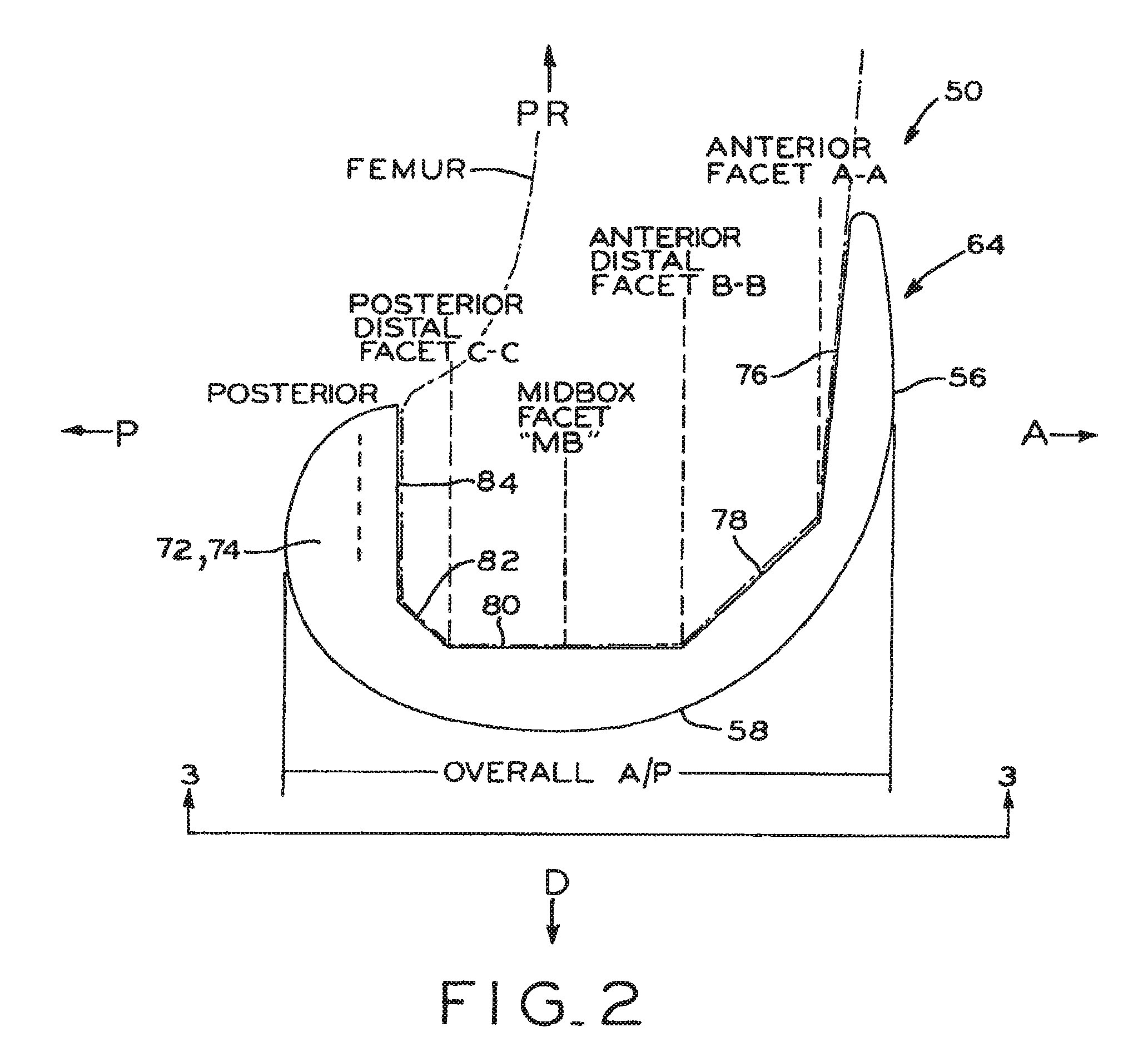
1. A set of distal femoral prostheses particularly adapted for female anatomy, each femoral prosthesis including a distal nonarticulating surface having an anterior end and a posterior end, comprising: a plurality of standard aspect ratio prostheses including first, second, third and fourth prostheses, each of the first, second, third and fourth prostheses having in sequence from the first prosthesis to the fourth prosthesis, progressively greater overall anterior/posterior dimensions defined between points located most anteriorly and most posteriorly on each prosthesis and each of the first, second, third and fourth prostheses having, in sequence from the first prosthesis to the fourth prosthesis, progressively greater distal taper angles defined between a lateral line connecting the anterior end and the posterior end of the distal nonarticulating surface and a medial line connecting the anterior end and the posterior end of the distal nonarticulating surface on each prosthesis; at least some of said prostheses having a said distal taper angle greater than or equal to 21.degree. up to and including 35.degree..
2. The set of distal femoral prostheses of claim 1, wherein at least some of said prostheses have a said distal taper angle between 23.degree. and 27.degree..
3. The set of distal femoral prostheses of claim 1, wherein: said distal taper angles of said first, second, third and fourth prostheses respectively increase at a first rate, and said overall anterior/posterior dimensions of said first, second, third and fourth prostheses respectively increase at a second rate, said first rate and said second rate defining a ratio of approximately 0.28; and all of said prostheses have a distal taper angle greater than or equal to 21.degree. up to and including 35.degree..
4. The set of distal femoral prostheses of claim 3, wherein the plurality of standard aspect ratio prostheses includes a fifth prosthesis and wherein the overall anterior/posterior dimension and the distal taper angle of the fifth prosthesis are greater than those of the fourth prosthesis.
5. The set of distal femoral prostheses of claim 4, wherein: the first prosthesis has a distal taper angle of approximately 21.degree. and an overall anterior/posterior dimension of approximately 53 mm; and the fifth prosthesis has a distal taper angle of approximately 27.degree. and an overall anterior/posterior dimension of approximately 70 mm.
6. The set of distal femoral prostheses of claim 5, wherein the second prosthesis has a distal taper angle of approximately 23.degree. and an overall anterior/posterior dimension of approximately 57 mm.
7. The set of distal femoral prostheses of claim 5, wherein the third prosthesis has a distal taper angle of approximately 24.degree. and an overall anterior/posterior dimension of approximately 61 mm.
8. The set of distal femoral prostheses of claim 5, wherein the fourth prosthesis has a distal taper angle of approximately 26.degree. and an overall anterior/posterior dimension of approximately 65 mm.
9. The set of distal femoral prostheses of claim 1, wherein said distal taper angles of said first, second, third and fourth prostheses respectively increase at a first rate from the first prosthesis to the fourth prosthesis, and said overall anterior/posterior dimensions of said first, second, third and fourth prostheses respectively increase at a second rate from the first prosthesis to the fourth prosthesis, said first rate and said second rate defining a ratio equal to or greater than 0.22 up to and including 0.42.
10. A set of distal femoral prostheses particularly adapted for female anatomy, each femoral prosthesis including a distal nonarticulating surface having an anterior end and a posterior end, comprising: a plurality of prostheses including first, second and third prostheses, each of the first, second and third prostheses having, in sequence from the first prosthesis to the third prosthesis, progressively greater overall anterior/posterior dimensions defined between points located most anteriorly and most posteriorly on each prosthesis and each of the first, second and third prostheses having, in sequence from the first prosthesis to the third prosthesis, progressively greater distal taper angles defined between a lateral line connecting the anterior end and the posterior end of the distal nonarticulating surface and a medial line connecting the anterior end and the posterior end of the distal nonarticulating surface on each prosthesis; at least some of said overall anterior/posterior dimensions and said distal taper angles falling within a conceptual boundary defined by an upper boundary and a lower boundary, said upper boundary defined by a line connecting a first point and a third point, said lower boundary defined by a line connecting a second point and a fourth point, said first point having a 52.0 mm overall anterior/posterior dimension and a 27.0.degree. distal taper angle, said second point having a 58.0 mm overall anterior/posterior dimension and a 22.5.degree. distal taper angle, said third point having a 77.0 mm overall anterior/posterior dimension and a 32.0.degree. distal taper angle, and said fourth point having a 77.0 mm overall anterior/posterior dimension and a 26.0.degree. distal taper angle.
11. The set of distal femoral prostheses of claim 10, wherein all of said overall anterior/posterior dimensions and said distal taper angles fall with said conceptual boundary.
12. The set of distal femoral prostheses of claim 10, wherein said conceptual boundary defines a four-sided polygon.
13. The set of distal femoral prostheses of claim 10, wherein said distal taper angles of said prostheses respectively increase at a first rate from the first prosthesis to the third prosthesis, said overall anterior/posterior dimensions respectively increase at a second rate from the first prosthesis to the third prosthesis, said first rate and said second rate defining a ratio equal to or greater than 0.22 up to and including 0.42.
14. A set of distal femoral prostheses particularly adapted for female anatomy, each femoral prosthesis including a distal nonarticulating surface having an anterior end and a posterior end, comprising: a plurality of prostheses including first, second and third prostheses, each of the first, second and third prostheses having in sequence from the first prosthesis to the third prosthesis, progressively greater overall anterior/posterior dimensions defined between points located most anteriorly and most posteriorly on each prosthesis and each of the first, second and third prostheses having in sequence from the first prosthesis to the third prosthesis, progressively greater distal taper angles defined between a lateral line connecting the anterior end and the posterior end of the distal nonarticulating surface and a medial line connecting the anterior end and the posterior end of the distal nonarticulating surface on each prosthesis; at least some of said overall anterior/posterior dimensions and said distal taper angles falling within a conceptual boundary defined by an upper boundary and a lower boundary, said upper boundary defined by a line connecting a first point and a third point, said lower boundary defined by a line connecting a second point and a fourth point, said first point having a 52.0 mm overall anterior/posterior dimension and a 34.0.degree. distal taper angle, said second point having a 58.0 mm overall anterior/posterior dimension and a 22.5.degree. distal taper angle, said third point having a 77.0 mm overall anterior/posterior dimension and a 32.0.degree. distal taper angle, and said fourth point having a 77.0 mm overall anterior/posterior dimension and a 26.0.degree. distal taper angle.
15. The set of distal femoral prostheses of claim 14, wherein all of said overall anterior/posterior dimensions and said distal taper angles fall with said conceptual boundary.
16. The set of distal femoral prostheses of claim 14, wherein said conceptual boundary defines a four-sided polygon.
17. The set of distal femoral prostheses of claim 14, wherein said distal taper angles of said prostheses respectively increase at a first rate from the first prosthesis to the third prosthesis, said overall anterior/posterior dimensions respectively increase at a second rate from the first prosthesis to the third prosthesis, said first rate and said second rate defining a ratio equal to or greater than 0.22 up to and including 0.42.
Description
BACKGROUND
1. Field of the Invention
The present invention relates generally to orthopedic prosthetic devices and, in particular, to distal femoral knee prostheses.
2. Description of the Related Art
Disease and trauma affecting the articular surfaces of a knee joint are commonly effectively treated by surgically replacing the articulating ends of the femur and tibia with prosthetic femoral and tibial implants or prostheses according to a procedure known as a total knee replacement ("TKR") or a total knee arthroplasty ("TKA"). The femoral and tibial implants are made of materials that exhibit a low coefficient of friction as they articulate against one another to restore normal knee function.
Although distal femoral knee prostheses are provided in a range of varying sizes and are selected by surgeons to best fit the anatomy of a particular patient, improvements in the design of distal femoral knee prostheses are desired.
SUMMARY
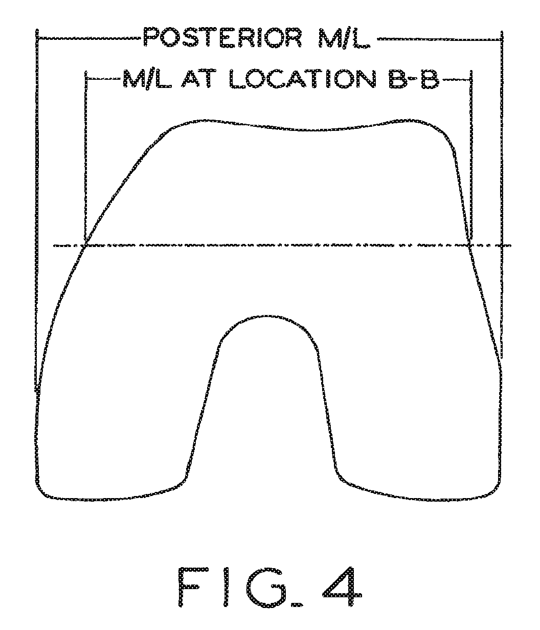
The present invention provides a set of distal femoral knee prostheses which are designed to be more narrow in medial/lateral ("M/L") dimensions with increasing anterior/posterior ("A/P") size than existing prostheses to more closely correspond to the physical anatomy of female patients. The prostheses are designed to have a substantially trapezoidal shape or profile when viewed distally which features a more pronounced narrowing of the M/L dimensions beginning at the posterior end of the prostheses and progressing anteriorly to the anterior end of the prostheses. Additionally, the prostheses each include a reduced profile patellar sulcus and reduced profile anterior condyles to more closely conform to the anatomy of a resected femur, and also include sulcus tracking which is optimized to conform to female anatomy.
In one form thereof, the present disclosure provides a set of distal femoral prostheses particularly adapted for female anatomy, each femoral prosthesis including a distal nonarticulating surface having an anterior end and a posterior end, including a plurality of standard aspect ratio prostheses respectively having increasingly greater overall anterior/posterior dimensions defined between points located most anteriorly and most posteriorly on each prosthesis and having increasingly greater distal taper angles defined between a lateral line connecting the anterior end and the posterior end of the distal nonarticulating surface and a medial line connecting the anterior end and the posterior end of the distal nonarticulating surface on each prosthesis: at least some of the prostheses having a distal taper angle greater than or equal to approximately 21.degree..
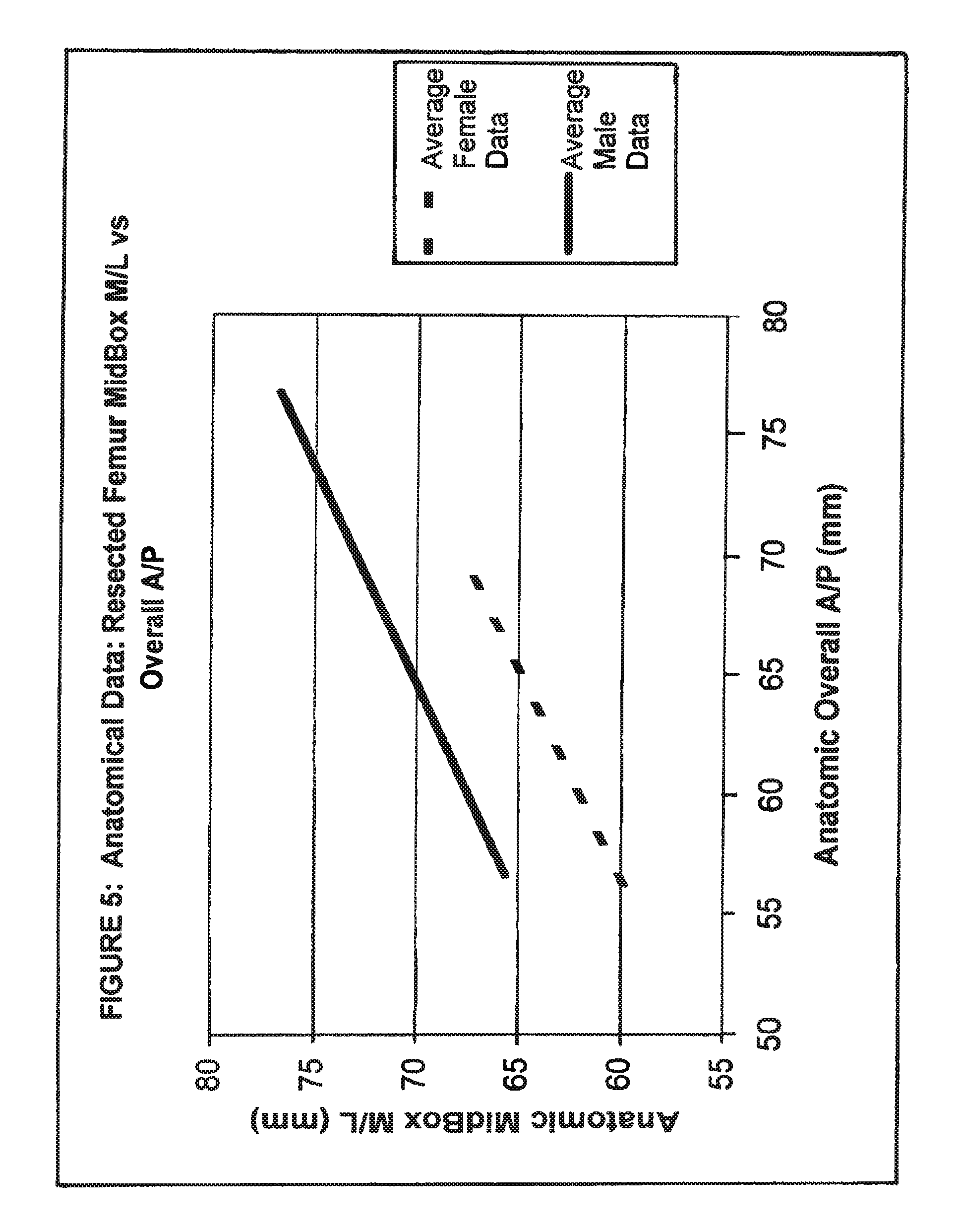
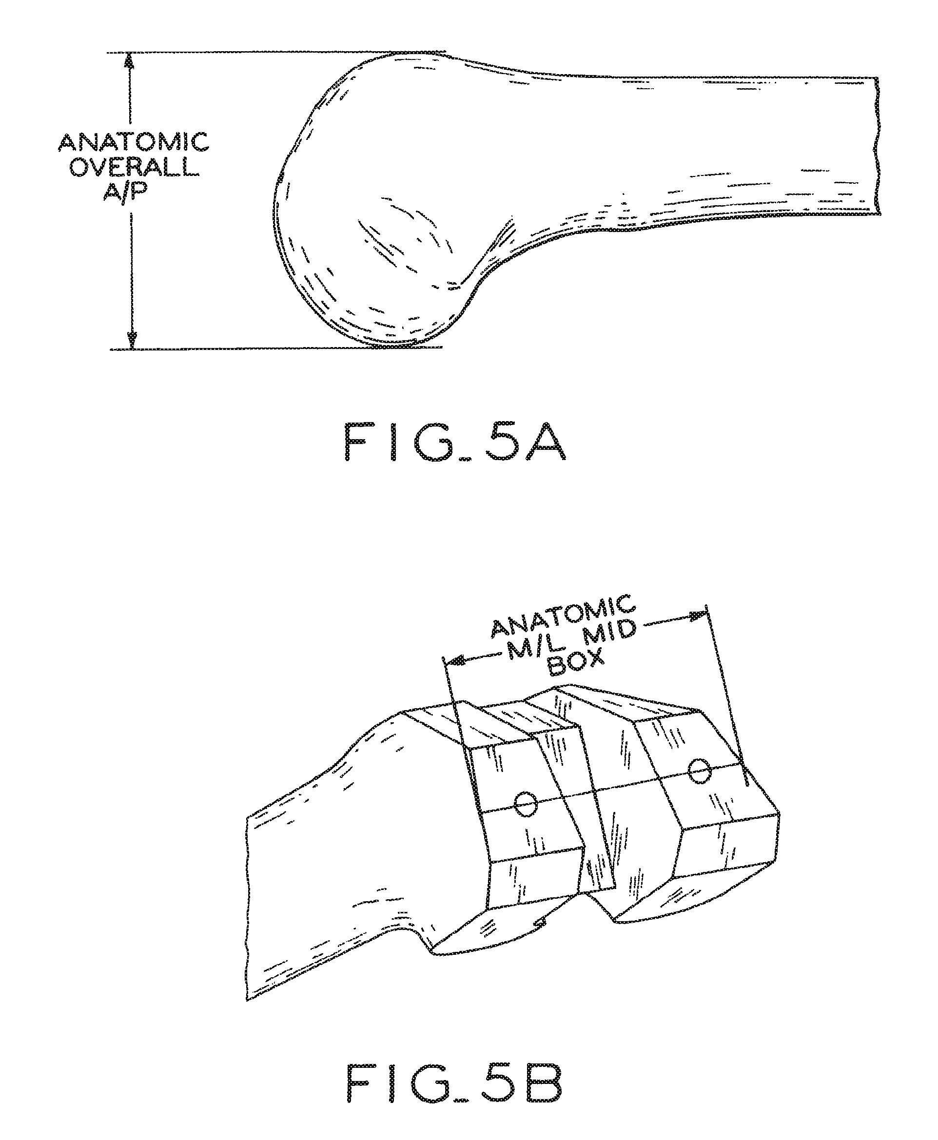
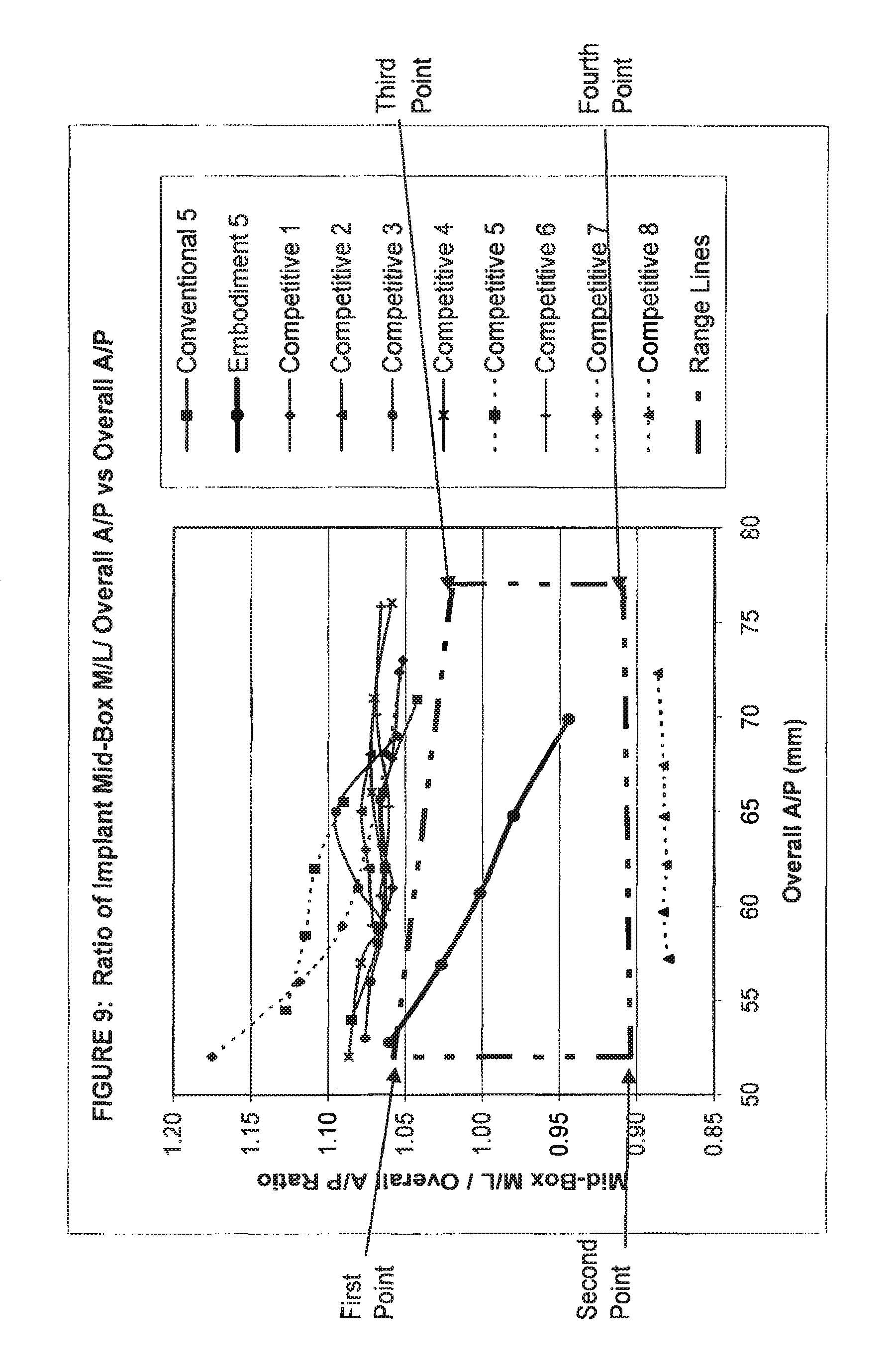
In another form thereof, the present disclosure provides a set of distal femoral prostheses particularly adapted for female anatomy, each femoral prosthesis including a distal nonarticulating surface having an anterior end and a posterior end, including a plurality of standard aspect ratio prostheses each having an overall anterior/posterior dimension defined between points located most anteriorly and most posteriorly on each prosthesis and a medial/lateral dimension defined between points located most medially and most laterally at anterior/posterior locations substantially equidistant from the anterior end of the distal nonarticulating surface and the posterior end of the distal nonarticulating surface; at least some of the prostheses having an overall anterior/posterior dimension and a medial/lateral dimension falling below a conceptual boundary defined by a line connecting a first point and a second point, the first point having an approximately 52.0 overall anterior/posterior dimension and an approximately 55.0 medial/lateral dimension, and the second point having an approximately 77.0 overall anterior/posterior dimension and an approximately 78.5 medial/lateral dimension; wherein the line is defined by the following equation: (medial/lateral dimension)=(0.94*overall anterior/posterior dimension)+6.12.
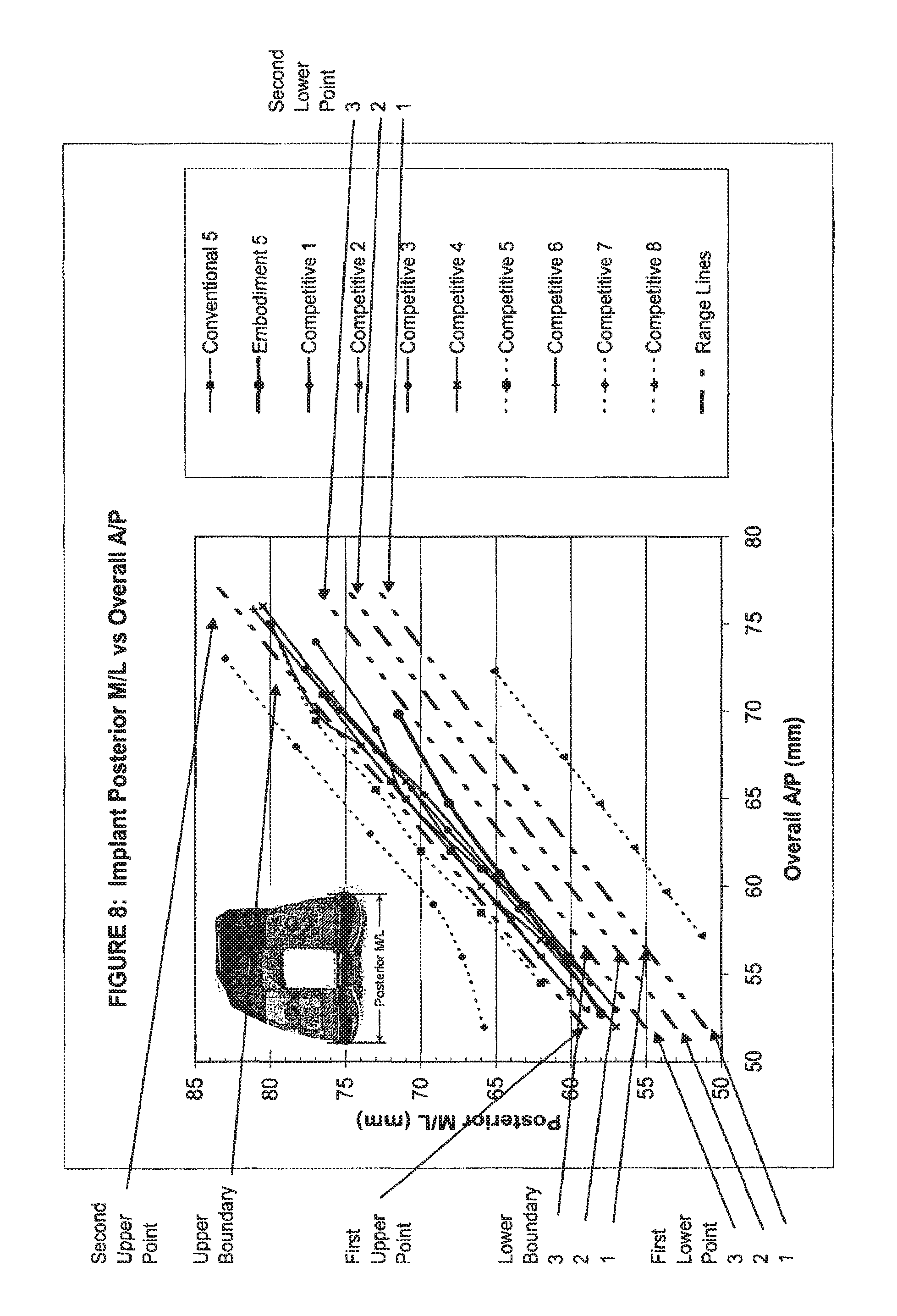
In yet another form thereof, the present disclosure provides a set of distal femoral prostheses particularly adapted for female anatomy, each femoral prosthesis including a distal nonarticulating surface having an anterior end and a posterior end, including a plurality of standard aspect ratio prostheses respectively having increasingly greater overall anterior/posterior dimensions defined between points located most anteriorly and most posteriorly on each prosthesis and respectively having increasingly greater medial/lateral dimensions defined between points located most medially and most laterally at an anterior/posterior location defined by the anterior end of the distal nonarticulating surface on each prosthesis: at least some of the prostheses having an overall anterior/posterior dimension and a medial/lateral dimension falling below a conceptual boundary defined by a line connecting a first point and a second point, the first point having an approximately 52.0 overall anterior/posterior dimension and an approximately 50.0 medial/lateral dimension, and the second point having an approximately 77.0 overall anterior/posterior dimension and an approximately 70.5 medial/lateral dimension; wherein the line is defined by the following equation: (medial/lateral dimension)=(0.82*overall anterior/posterior dimension)+7.36.
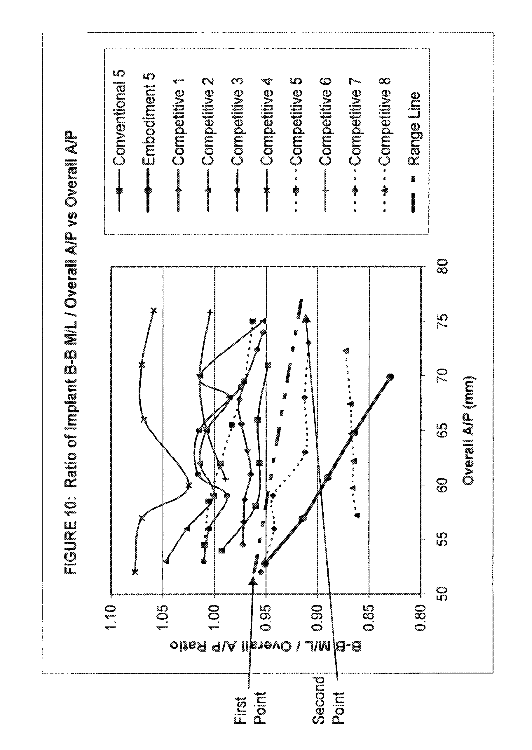
In still another form thereof, the present disclosure provides a set of distal femoral prostheses particularly adapted for female anatomy, each femoral prosthesis including a distal nonarticulating surface and an anterior nonarticulating surface, including a plurality of standard aspect ratio prostheses respectively having increasingly greater overall anterior/posterior dimensions defined between points located most anteriorly and most posteriorly on each prosthesis and respectively having increasingly greater medial/lateral dimensions defined between points located most medially and most laterally at an anterior/posterior location defined by a distal most point on the anterior nonarticulating surface on each prosthesis; at least some of the prostheses having an overall anterior/posterior dimension and a medial/lateral dimension falling below a conceptual boundary defined by a line connecting a first point and a second point, the first point having an approximately 52.0 overall anterior/posterior dimension and an approximately 40.1 medial/lateral dimension, and the second point having an approximately 77.0 overall anterior/posterior dimension and an approximately 53.5 medial/lateral dimension; wherein the line is defined by the following equation: (medial/lateral dimension)=(0.54*overall anterior/posterior dimension)+12.23.
In another form thereof, the present disclosure provides a set of distal femoral prostheses particularly adapted for female anatomy, each femoral prosthesis including a distal nonarticulating surface and an anterior nonarticulating surface, including a plurality of prostheses respectively having increasingly greater overall anterior/posterior dimensions defined between points located most anteriorly and most posteriorly on each prosthesis and respectively having increasingly greater medial/lateral dimensions defined between points located most medially and most laterally at an anterior/posterior location defined by a distal most point on the anterior nonarticulating surface on each prosthesis; at least some of the prostheses having an overall anterior/posterior dimension and a medial/lateral dimension falling below a conceptual boundary defined by a line connecting a first point and a second point, the first point having an approximately 52.0 overall anterior/posterior dimension and an approximately 40.3 medial/lateral dimension, and the second point having an approximately 77.0 overall anterior/posterior dimension and an approximately 51.8 medial/lateral dimension; wherein the line is defined by the following equation: (medial/lateral dimension)=(0.46*overall anterior/posterior dimension)+16.38.
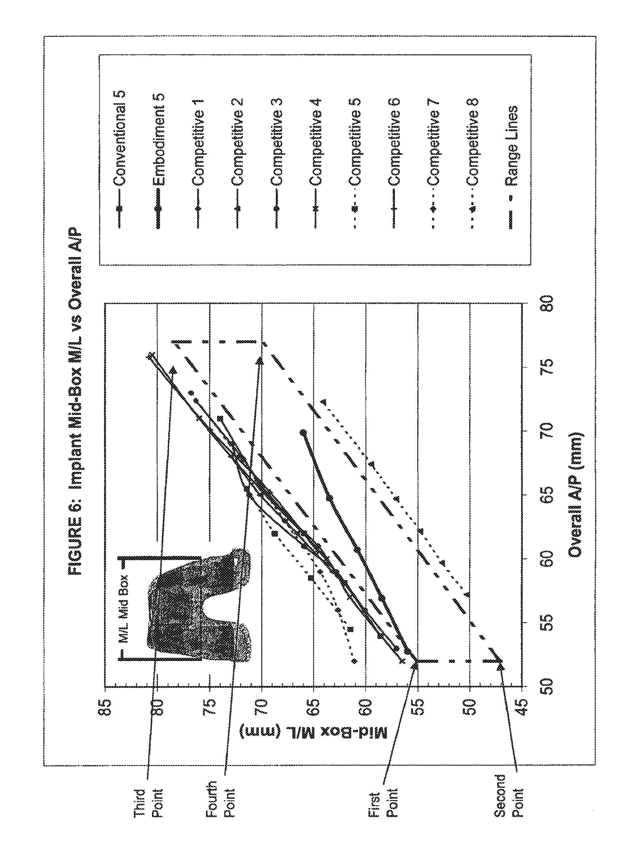
In a still further form thereof, the present disclosure provides a set of distal femoral prostheses particularly adapted for female anatomy, each femoral prosthesis including a distal nonarticulating surface having an anterior end and a posterior end, including a plurality of prostheses each having an overall anterior/posterior dimension defined between points located most anteriorly and most posteriorly on each prosthesis and a medial/lateral dimension defined between points located most medially and most laterally at anterior/posterior locations substantially equidistant from the anterior end of the distal nonarticulating surface and the posterior end of the distal nonarticulating surface; at least some of the overall anterior/posterior dimensions and the medial/lateral dimensions falling within a conceptual boundary defined by an upper line and a lower line, the upper line connecting a first point and a third point, the lower line connecting a second point and a fourth point, the first point having an approximately 52.0 overall anterior/posterior dimension and an approximately 55.0 medial/lateral dimension, the second point having an approximately 52.0 overall anterior/posterior dimension and an approximately 47.0 medial/lateral dimension, the third point having an approximately 77.0 overall anterior/posterior dimension and an approximately 78.5 medial/lateral dimension, and the fourth point having an approximately 77.0 overall anterior/posterior dimension and an approximately 70.0 medial/lateral dimension; wherein the upper line is defined by the following equation: (medial/lateral dimension)=(0.94*overall anterior/posterior dimension)+6.12; and wherein the lower line is defined by the following equation: (medial/lateral dimension)=(0.92*overall anterior/posterior dimension)-0.84.
In yet another form thereof, the present disclosure provides a set of distal femoral prostheses particularly adapted for female anatomy, each femoral prosthesis including a distal nonarticulating surface having an anterior end and a posterior end, including a plurality of standard aspect ratio prostheses respectively having increasingly greater overall anterior/posterior dimensions defined between points located most anteriorly and most posteriorly on each prosthesis and having increasingly greater medial/lateral dimensions defined between points located most medially and most laterally at an anterior/posterior location substantially equidistant from the anterior end of the distal nonarticulating surface and the posterior end of the distal nonarticulating surface on each prosthesis; the medial/lateral dimensions of the prostheses respectively increasing at a first rate, the overall anterior/posterior dimensions respectively increasing at a second rate, the first rate and the second rate defining a ratio substantially equal to or less than 0.89.
In still another form thereof, the present disclosure provides a set of distal femoral prostheses particularly adapted for female anatomy, each femoral prosthesis including a distal nonarticulating surface having an anterior end and a posterior end, including a plurality of prostheses respectively having increasingly greater overall anterior/posterior dimensions defined between points located most anteriorly and most posteriorly on each prosthesis and having increasingly greater medial/lateral dimensions defined between points located most medially and most laterally at an anterior/posterior location substantially equidistant from the anterior end of the distal nonarticulating surface and the posterior end of the distal nonarticulating surface on each prosthesis: the medial/lateral dimensions of the prostheses respectively increasing at a first rate, the overall anterior/posterior dimensions respectively increasing at a second rate, the first rate and the second rate defining a ratio substantially equal to or less than 0.75.
In a further form thereof, the present disclosure provides a set of distal femoral prostheses particularly adapted for female anatomy, including a plurality of standard aspect ratio prostheses respectively having increasingly greater overall anterior/posterior dimensions defined between points located most anteriorly and most posteriorly on each prosthesis and having increasingly greater medial/lateral dimensions defined between points located most medially and most laterally at an anterior/posterior location defined at a location proximate the most posteriorly located point on each prosthesis; the medial/lateral dimensions of the prostheses respectively increasing at a first rate, the overall anterior/posterior dimensions respectively increasing at a second rate, the first rate and the second rate defining a ratio substantially equal to or less than 0.96.
In another form thereof, the present disclosure provides a set of distal femoral prostheses particularly adapted for female anatomy, including a plurality of prostheses respectively having increasingly greater overall anterior/posterior dimensions defined between points located most anteriorly and most posteriorly on each prosthesis and having increasingly greater medial/lateral dimensions defined between points located most medially and most laterally at an anterior/posterior location defined at a location proximate the most posteriorly located point on each prosthesis; the medial/lateral dimensions of the prostheses respectively increasing at a first rate, the overall anterior/posterior dimensions respectively increasing at a second rate, the first rate and the second rate defining a ratio substantially equal to or less than 0.84.
In still another form thereof, the present disclosure provides a set of distal femoral prostheses particularly adapted for female anatomy, each femoral prosthesis including a distal nonarticulating surface having an anterior end and a posterior end, including a plurality of standard aspect ratio prostheses respectively having increasingly greater overall anterior/posterior dimensions defined between points located most anteriorly and most posteriorly on each prosthesis and respectively having increasingly greater medial/lateral dimensions defined between points located most medially and most laterally at an anterior/posterior location defined by the anterior end of the distal nonarticulating surface on each prosthesis; the medial/lateral dimensions of the prostheses respectively increasing at a first rate, the overall anterior/posterior dimensions respectively increasing at a second rate, the first rate and the second rate defining a ratio substantially equal to or less than 0.78.
In yet another form thereof, the present disclosure provides a set of distal femoral prostheses particularly adapted for female anatomy, each femoral prosthesis including a distal nonarticulating surface having an anterior end and a posterior end, including a plurality of prostheses respectively having increasingly greater overall anterior/posterior dimensions defined between points located most anteriorly and most posteriorly on each prosthesis and respectively having increasingly greater medial/lateral dimensions defined between points located most medially and most laterally at an anterior/posterior location defined by the anterior end of the distal nonarticulating surface on each prosthesis; the medial/lateral dimensions of the prostheses respectively increasing at a first rate, the overall anterior/posterior dimensions respectively increasing at a second rate, the first rate and the second rate defining a ratio substantially equal to or less than 0.76.
In another form thereof, the present disclosure provides a set of distal femoral prostheses particularly adapted for female anatomy, each femoral prosthesis including a distal nonarticulating surface and an anterior nonarticulating surface, including a plurality of standard aspect ratio prostheses respectively having increasingly greater overall anterior/posterior dimensions defined between points located most anteriorly and most posteriorly on each prosthesis and respectively having increasingly greater medial/lateral dimensions defined between points located most medially and most laterally at an anterior/posterior location defined by a distal most point on the anterior nonarticulating surface on each prosthesis; the medial/lateral dimensions of the prostheses respectively increasing at a first rate, the overall anterior/posterior dimensions respectively increasing at a second rate, the first rate and the second rate defining a ratio substantially equal to or less than 0.44.
In a further form thereof, the present disclosure provides a set of distal femoral prostheses particularly adapted for female anatomy, each femoral prosthesis including a distal nonarticulating surface having an anterior end and a posterior end, including a plurality of prostheses respectively having increasingly greater overall anterior/posterior dimensions defined between points located most anteriorly and most posteriorly on each prosthesis and having increasingly greater distal taper angles defined between a lateral line connecting the anterior end and the posterior end of the distal nonarticulating surface and a medial line connecting the anterior end and the posterior end of the distal nonarticulating surface on each prosthesis; the distal taper angles of the prostheses respectively increasing at a first rate, the overall anterior/posterior dimensions of the prostheses respectively increasing at a second rate, the first rate and the second rate defining a ratio substantially equal to or greater than 0.22.
In still another form thereof, the present disclosure provides a set of distal femoral prostheses particularly adapted for female anatomy, each femoral prosthesis including a distal nonarticulating surface having an anterior end and a posterior end, including a plurality of prostheses respectively having increasingly greater overall anterior/posterior dimensions defined between points located most anteriorly and most posteriorly on each prosthesis and having increasingly greater distal taper angles defined between a lateral line connecting the anterior end and the posterior end of the distal nonarticulating surface and a medial line connecting the anterior end and the posterior end of the distal nonarticulating surface on each prosthesis; at least some of the overall anterior/posterior dimensions and the distal taper angles falling within a conceptual boundary defined by an upper boundary and a lower boundary, the upper boundary defined by a line connecting a first point and a third point, the lower boundary defined by a line connecting a second point and a fourth point, the first point having an approximately 52.0 overall anterior/posterior dimension and an approximately 27.00 distal taper angle, the second point having an approximately 58.0 overall anterior/posterior dimension and an approximately 22.5.degree. distal taper angle, the third point having an approximately 77.0 overall anterior/posterior dimension and an approximately 32.00 distal taper angle, and the fourth point having an approximately 77.0 overall anterior/posterior dimension and an approximately 26.0.degree. distal taper angle.
In yet another form thereof, the present disclosure provides a set of distal femoral prostheses particularly adapted for female anatomy, each femoral prosthesis including a distal nonarticulating surface having an anterior end and a posterior end, including a plurality of prostheses respectively having increasingly greater overall anterior/posterior dimensions defined between points located most anteriorly and most posteriorly on each prosthesis and having increasingly greater distal taper angles defined between a lateral line connecting the anterior end and the posterior end of the distal nonarticulating surface and a medial line connecting the anterior end and the posterior end of the distal nonarticulating surface on each prosthesis; at least some of the overall anterior/posterior dimensions and the distal taper angles falling within a conceptual boundary defined by an upper boundary and a lower boundary, the upper boundary defined by a line connecting a first point and a third point, the lower boundary defined by a line connecting a second point and a fourth point, the first point having an approximately 52.0 overall anterior/posterior dimension and an approximately 34.00 distal taper angle, the second point having an approximately 58.0 overall anterior/posterior dimension and an approximately 22.5.degree. distal taper angle, the third point having an approximately 77.0 overall anterior/posterior dimension and an approximately 32.00 distal taper angle, and the fourth point having an approximately 77.0 overall anterior/posterior dimension and an approximately 26.0.degree. distal taper angle.
In a further form thereof, the present disclosure provides a distal femoral prosthesis, including a non-articulating surface including a distal plane and an anterior non-articular surface; lateral and medial anterior condyles; a patellar sulcus defined between the condyles, the patellar sulcus having a maximum thickness between approximately 2.5 mm and 3.2 mm between an anterior most point on the sulcus and the anterior non-articular surface.
In another form thereof, the present disclosure provides a distal femoral prosthesis, including a non-articulating surface including a distal plane and an anterior non-articular surface; lateral and medial anterior condyles each defining an anterior articular surface, at least one of the condyles having a maximum thickness between approximately 4.0 mm and 6.1 mm between an anterior most point on the anterior articular surface of the condyle and the anterior non-articular surface.
In yet another form thereof, the present disclosure provides a distal femoral prosthesis, including a patellar sulcus disposed between lateral and medial anterior condyles of the prosthesis, the sulcus having an end point; a non-articulating surface having a distal plane; and a lateralization distance defined at the end point between a first line extending from an intersection of the distal plane and the sulcus and the end point, the lateralization distance greater than 5.0 mm.
BRIEF DESCRIPTION OF THE DRAWINGS
The above-mentioned and other features and advantages of this invention, and the manner of attaining them, will become more apparent and the invention itself will be better understood by reference to the following description of embodiments of the invention taken in conjunction with the accompanying drawings, wherein:
FIG. 1 is a side view of an exemplary distal femoral prosthesis in accordance with the present invention;
FIG. 2 is another side view of the prosthesis of FIG. 1, illustrating certain dimensions thereof;
FIG. 3 is a distal view of the prosthesis of FIG. 2, viewed along line 3-3 of FIG. 2 and shown superimposed on a known prosthesis;
FIG. 4 further illustrates the anatomical M/L vs. A/P dimensional relationship of the prosthesis of FIG. 3 at dimension "B-B";
FIG. 5 is a graph illustrating a representative anatomical mid-box M/L vs. A/P dimensional relationship with respect to male and female femurs of various size;
FIG. 5A is a view of an anatomic overall A/P dimension for a representative femur,
FIG. 5B is a view of an anatomic mid-box M/L dimension for a representative femur;
FIG. 6 is a graph of mid-box M/L vs. overall A/P for prostheses designed in accordance with the present invention as compared with several known prostheses;
FIG. 7 is a graph of anterior M/L along a dimension "B-B" vs. overall A/P for prostheses designed in accordance with the present invention as compared with several known prostheses;
FIG. 8 is a graph of posterior M/L vs. overall A/P for prostheses designed in accordance with the present invention as compared with several known prostheses;
FIG. 9 is a graph of the ratio of (mid-box M/L/overall A/P) vs. overall A/P for the prostheses of FIG. 6;
FIG. 10 is a graph of the ratio of (anterior M/L along dimension "B-B"/overall A/P) vs. overall A/P for the prostheses of FIG. 7;
FIG. 11 is a graph of the ratio of (posterior M/L/overall A/P) vs. overall A/P for the prostheses of FIG. 8;
FIG. 12 is a distal view of an exemplary prosthesis designed in accordance with the present invention, shown superimposed on a known prosthesis and illustrating the profiles and the distal taper angles of same;
FIG. 13 is a graph of distal taper angle vs. overall A/P for prostheses designed in accordance with the present invention as compared with several known prostheses;
FIG. 14 is a distal view of an exemplary prosthesis;
FIG. 15 is a side view of the prosthesis of FIG. 14, illustrating the recessed patellar sulcus thereof as compared with a known prosthesis;
FIG. 16 is another side view of the prosthesis of FIG. 14, illustrating the reduced profile of the anterior condyles thereof as compared with a known prosthesis;
FIG. 17A is an A/P view of a known prosthesis having conventional sulcus tracking;
FIG. 17B is an A/P view of an exemplary prosthesis in accordance with the present invention having a more lateralized sulcus tracking;
FIG. 18 is a graph of A-A M/L vs. overall A/P for prostheses designed in accordance with the present invention as compared with several known prostheses; and
FIG. 19 is a graph of the ratio of (A-A M/L/overall A/P) vs. overall A/P for the prostheses of FIG. 18.
Corresponding reference characters indicate corresponding parts throughout the several views. The exemplifications set out herein illustrate exemplary embodiments of the invention, and such exemplifications are not to be construed as limiting the scope of the invention any manner.
DETAILED DESCRIPTION
As used herein, the following directional definitions apply. Anterior and posterior mean nearer the front or nearer the rear of the body, respectively. Thus, with respect to the prostheses described herein, anterior refers to that portion of the knee that is nearer the front of the body, when the leg is in an extended position. Proximal and distal mean nearer to or further from the root of a structure, respectively. For example, the distal femur is a part of the knee joint while the proximal femur is part of the hip joint. Finally, the adjectives medial and lateral mean nearer the sagittal plane or further from the sagittal plane, respectfully. The sagittal plane is an imaginary vertical plane through the middle of the body that divides the body into right and left halves.
Distal femoral knee prostheses made in accordance with the present invention are intended to be used to restore knee joint function in patients with severe pain and disability due, for example, to Rheumatoid arthritis, osteoarthritis, traumatic arthritis polyarthritis; collagen disorders, and/or avascular necrosis of the femoral condyle; post-traumatic loss of joint configuration, particularly when there is patellofemoral erosion, dysfunction or prior patellectonmy; moderate valgus, varus, flexion deformities, or other conditions.
Referring initially to FIG. 1, a distal femoral prosthesis 50 for a TKR/TKA according to one embodiment of the present invention is shown, and generally includes an external articulating surface 52 and a bone contacting non-articulating internal surface 54. Articulating surface 52 includes an anterior articulating surface 56, a distal articulating surface 58, a lateral posterior condylar articulating surface 60, and a medial posterior condylar articulating surface 62. Prosthesis 50 may be made of any biocompatible material having the mechanical properties necessary to function as a human knee distal femoral prosthesis. Preferably, prosthesis 50 is made of titanium, titanium alloy, cobalt chrome alloy, stainless steel, or a ceramic. Referring additionally to FIG. 3, prosthesis 50 further includes patellar flange 64 including lateral and medial anterior condyles 66 and 68, respectively, as well as patellar sulcus 70 disposed between lateral and medial anterior condyles 66 and 68. Prosthesis also includes lateral and medial posterior condyles 72 and 74, respectively.
Referring to FIG. 1, the internal non-articulating portion 54 of prosthesis 50 is adapted to receive a resected distal femur. The surgical cuts made to the distal femur can be made by any means, in any sequence and in any configuration known to those of skill in the art of knee arthroplasty. Exemplary cut guides and processes for resecting the distal femur are shown and described in U.S. patent application Ser. No. 11/151,062, entitled ADJUSTABLE CUT GUIDE, filed on Jun. 13, 2005 and U.S. patent application Ser. No. 11/154,774, entitled MULTI-POSITIONABLE CUT GUIDE, filed on Jun. 16, 2005, assigned to the assignee of the present invention, the disclosures of which are expressly incorporated herein by reference.
In a preferred embodiment, prosthesis 50 comprises a plurality of chamfer surfaces corresponding to a plurality of chamfer surfaces or "box cuts" made in the distal femur. Non-articular surface 54 may comprise a porous metal surface or any surface likely to promote the growth of bone therein. Non-articular surface 54 of prosthesis 50 preferably comprises anterior non-articular surface 76, distal anterior non-articular surface 78, distal non-articular surface 80, two distal posterior non-articular surfaces 82, and two posterior non-articular surfaces 84.
Distal non-articular surface 80 is generally flat and adapted to receive the distal-most surface of the resected femur. Distal non-articular surface 80 comprises an anterior end and a posterior end. The anterior end of distal non-articular surface 80 abuts one end of distal anterior non-articular surface 78, which surface 78 also includes an anterior end and a posterior end. Surface 78 extends from surface 80 anteriorly and superiorly such that an obtuse angle is formed between surfaces 78 and 80. Anterior non-articular surface 76 extends superiorly from the anterior end of surface 78.
The posterior end of distal non-articular surface 80 abuts one end of each distal posterior non-articular surface 82, which surfaces 82 also include an anterior end and a posterior end. Surfaces 82 extend from surface 80 posteriorly and superiorly such that an obtuse angle is formed between surfaces 82 and 80. Posterior non-articular surfaces 84 extend superiorly from the posterior ends of surfaces 82, respectively.
As discussed in detail below, for many patients, particularly female patients, it is desirable to construct a set of prostheses 50 of varying size wherein the medial/lateral ("M/L") width dimensions of the prostheses correspond more closely to the actual anatomical M/L width dimensions of the female femur and articulating surfaces. As described below, prostheses 50 addresses this concern by offering the surgeon a set of narrower prostheses in the M/L dimensions for a given set of anterior/posterior ("A/P") prosthesis sizes which will allow the surgeon to use a prosthesis with both a correct A/P size and more accurate and optimized M/L dimensions to provide optimal prosthesis sizing and joint kinematics as compared to conventional prostheses.
In FIG. 3, the profile 86 of prosthesis 50 is superimposed upon profile 88 of a known prosthesis. As described in detail below, prosthesis 50 has a unique, substantially trapezoidal shape or profile 86 when viewed distally with a more pronounced narrowing of the M/L dimensions as compared to the shape or profile 88 of a known prosthesis starting, with reference to the resected femur, at the posterior distal facet and progressing anteriorly to the anterior distal facet. Referring to FIGS. 2 and 3, prosthesis 50 is shown and is characterized below with reference to the following directions: anterior "A", posterior "P", distal "D", proximal "PR", medial "M" and lateral "L", as well as the following dimensions. Dimension "Posterior" is the M/L width at the widest point across the posterior condyles 72, 74 of prosthesis 50. Dimension "C-C" is the M/L width at the junction of the posterior distal facet and the distal plane, i.e., the M/L width along the intersection between distal non-articular surface 80 and distal posterior non-articular surfaces 82. Dimension "B-B" is the M/L width at the junction of the distal plane and the distal anterior facet, i.e., the M/L width along the intersection between distal non-articular surface 80 and distal anterior non-articular surface 78. Dimension "A-A" is the M/L width at the junction of the distal anterior facet and the posterior side of the anterior flange, i.e., the M/L width along the intersection of distal anterior non-articular surface 78 and anterior non-articular surface 76. Dimension "MB" is the M/L width at a "mid-box" point of prosthesis 50, i.e., along a line located on distal non-articular surface 80 substantially midway between Dimension C-C and Dimension B-B.
As described below, the profiles of a set of prostheses 50 can also be described in terms of an increasing narrowing of the M/L dimensions relative to known prostheses on a per size basis. It has been observed that, for given female femurs, for example, the M/L dimensions are sometimes smaller than those of known prostheses of the proper A/P dimension. This discrepancy is small on the smaller A/P size prostheses and increases as the A/P size increases. For example, referring to FIG. 5, a representative mid-box M/L vs. A/P dimensional relationship with respect to the actual human anatomy of distal femurs for males and females is shown. Representative female data is generally grouped together at lower values of mid-box M/L and representative male data is generally grouped together at higher values of mid-box M/L. Best fit lines for female and male data have been included on FIG. 5 to show the general trend of representative mid-box M/L dimensions. As may be seen from FIG. 5, there exists a clear distinction between the representative M/L dimension vs. the A/P dimension for a female distal femur as compared to a male distal femur. FIGS. 5A and 5B show exemplary anatomic overall A/P and mid-box M/L dimensions for a representative femur.
In FIG. 2, the overall A/P ("Overall A/P") dimension is the distance between two lines perpendicular to distal non-articular surface 80 that pass through the most posterior point on the posterior face of exterior articulating surface 58 and through the most anterior point on the anterior face of exterior articulating surface 58, respectively. FIG. 2 also shows a dashed outline of a resected femur with prosthesis 50 positioned thereon.
As an exemplary comparison, the dimensions "Posterior", "B-B", "A-A", and "Overall A/P" and the ratios of these values for conventional prostheses ("Conventional 1", including five increasing sizes C through G) are compared with corresponding dimensions and ratios of a set of prostheses designed in accordance with the present invention ("Embodiment 1", including five increasing sizes C through G). These values are presented in Table 1 below. Unless otherwise indicated, all numerical dimensional values presented herein are in millimeters ("mm").
TABLE-US-00001 TABLE 1 SIZE Overall A/P "Post." "B-B" "A-A" Overall A/P "Post." "B-B" "A-A" Embodiment 1 Conventional 1 C 52.2 58.0 49.6 41.1 53.5 60.0 53.6 45.1 D 56.3 61.3 51.5 42.6 57.6 64.0 55.8 46.5 E 60.2 64.5 53.5 43.7 61.5 68.0 59.3 49.1 F 64.2 67.9 55.4 45.0 65.4 72.0 63.2 52.0 G 69.2 71.0 57.3 46.3 70.4 76.5 67.3 56.2 Embodiment 1 - M/L/"Overall Conventional 1 - M/L/"Overall A/P" RATIOS A/P" RATIOS C 52.2 1.11 0.95 0.79 53.5 1.12 1.00 0.84 D 56.3 1.09 0.92 0.76 57.6 1.11 0.97 0.81 E 60.2 1.07 0.89 0.73 61.5 1.11 0.96 0.80 F 64.2 1.06 0.86 0.70 65.4 1.10 0.97 0.79 G 69.2 1.03 0.83 0.67 70.4 1.09 0.96 0.80
Table 2 below sets forth the results of a first order equation fit to data sets for several sets of prostheses including Conventional 1, Conventional 2 (which is similar to Conventional 1), Embodiment 1, Embodiment 2 (which is similar to Embodiment 1), as well as five other sets of known competitive prostheses, designated Competitive 1, Competitive 2, Competitive 3, Competitive 4, and Competitive 5. The data sets include Posterior M/L vs. Overall A/P and the Ratio (Posterior M/L vs. Overall A/P) vs. Overall A/P.
TABLE-US-00002 TABLE 2 Ratio (Posterior M/L/ Posterior M/L Overall A/P) vs. Overall A/P vs. Overall A/P Best fit regression line Best fit regression line Equation Slope Equation Slope Conventional 1 y = 0.9811x + 0.9811 y = -0.002x + -0.0020 7.595 1.2277 Conventional 2 y = 0.9878x + 0.9878 y = -0.0015x + -0.0015 6.0634 1.1798 Embodiment 1 y = 0.8036x + 0.8036 y = -0.0044x + -0.0044 16.228 1.3431 Embodiment 2 y = 0.809x + 0.8090 y = -0.0039x + -0.0039 14.987 1.2965 Competitive 1 y = 0.9411x + 0.9411 y = -0.0016x + -0.0016 7.1008 1.1565 Competitive 2 y = 0.987x + 0.9870 y = -0.0017x + -0.0017 6.8225 1.2015 Competitive 3 y = 0.976x + 0.9760 y = -0.0013x + -0.0013 5.7825 1.1521 Competitive 4 y = 0.9757x + 0.9757 y = -0.0016x + -0.0016 6.6279 1.1836 Competitive 5 y = 0.9336x + 0.9336 y = -0.0031x + -0.0031 11.318 1.3111
From the data in Table 2, it may be seen that there is a difference in the slopes of the sets of prostheses of Embodiments 1 and 2 as compared to the slopes of the sets of the known prostheses. In particular, it may be seen from the data in Table 2 that the sets of prostheses of Embodiments 1 and 2 have a narrowing posterior M/L dimension with increasing A/P size, as indicated by slopes less than 0.93, for example, as opposed to a substantially parallel or one-to-one relationship between the posterior M/L dimension and the A/P dimension with increasing A/P size as in the sets of known prostheses, as indicated by slopes of 0.93 and above. Thus, in the sets of known prostheses, the posterior M/L dimension and the A/P dimension increase at substantially the same rate with increasing A/P size. Also, the slope of the ratio (posterior M/L/overall A/P) vs. overall A/P is less than -0.0032 for the sets of prostheses of Embodiments 1 and 2 while the corresponding slope for the known sets of prostheses is greater than -0.0032, indicating that the sets of prostheses of Embodiments 1 and 2 have an increasingly more pronounced narrowing of the posterior M/L dimension with increasing A/P size. In this manner, the sets of prostheses designed in accordance with the present invention offer a surgeon a unique combination of implant posterior M/L widths with varying A/P size for an overall system or set of prostheses, wherein such sets of prostheses are more anatomically optimized for the female anatomy as compared with the sets of known prostheses.
Table 3 below sets forth the results of a first order equation fit to data sets for several sets of prostheses including Conventional 1, Conventional 2 (which is similar to Conventional 1), Embodiment 1, Embodiment 2 (which is similar to Embodiment 1), as well as five other sets of known competitive prostheses, designated Competitive 1, Competitive 2, Competitive 3, Competitive 4, and Competitive 5. The data sets include B-B M/L vs. Overall A/P and the Ratio (B-B M/L vs. Overall A/P) vs. Overall A/P.
TABLE-US-00003 TABLE 3 Ratio (Anterior M/L "B-B"/ Anterior M/L "B-B" Overall A/P) vs. Overall A/P vs. Overall A/P Best fit regression line Best fit regression line Equation Slope Equation Slope Conventional 1 y = 0.834x + 0.8340 y = -0.0023x + -0.0023 8.3768 1.112 Conventional 2 y = 0.8432x + 0.8432 y = -0.0018x + -0.0018 6.9003 1.0681 Embodiment 1 y = 0.4626x + 0.4626 y = -0.0071x + -0.0071 25.012 1.3173 Embodiment 2 y = 0.4626x + 0.4626 y = -0.0066x + -0.0066 25.012 1.2797 Competitive 1 y = 0.9062x + 0.9062 y = -0.0007x + -0.0007 3.2306 1.0017 Competitive 2 y = 0.8057x + 0.8057 y = -0.0031x + -0.0031 12.588 1.2033 Competitive 3 y = 0.893x + 0.8930 y = -0.0012x + -0.0012 5.5381 1.0578 Competitive 4 y = 1.0588x + 1.0588 y = -0.0001x + -0.0001 0.1731 1.0697 Competitive 5 y = 0.7937x + 0.7937 y = -0.0036x + -0.0036 12.218 1.217
From the data in Table 3, it may be seen that there is a significant difference in slope for the sets of prostheses of Embodiments 1 and 2 as compared with the slopes of the known sets of prostheses. The magnitudes of the anterior M/L "B-B" values for a given A/P dimension are more pronounced, i.e., the variance in width at dimension B-B, namely, an anterior width, over various A/P sizes between the sets of prostheses of Embodiments 1 and 2 and the known sets of prostheses is more dramatically pronounced. Specifically, sets of prostheses of Embodiments 1 and 2 have a narrowing anterior M/L dimension with increasing A/P size, as indicated by slopes less than 0.78, for example, as opposed to a substantially parallel or one-to-one relationship between the anterior M/L dimension and the A/P dimension with increasing A/P size as in the sets of known prostheses, as indicated by slopes of 0.78 and above. Thus, in the sets of known prostheses, the anterior M/L dimension and the A/P dimension increase at substantially the same rate with increasing A/P size. Also, the slope of the ratio (anterior M/L "B-B"/overall A/P) vs. overall A/P is greater than -0.0038 for the sets of prostheses of Embodiments 1 and 2, while the corresponding slope for the known sets of prostheses is less than -0.0038, indicating that the sets of prostheses of Embodiments 1 and 2 have increasingly more pronounced narrowing of the anterior M/L "B-B" dimension with increasing A/P size. In this manner, the prostheses designed in accordance with the present invention offer a surgeon a unique combination of implant M/L widths as an overall system of prostheses, wherein such sets of prostheses are more anatomically optimized for the female anatomy as compared with the sets of known prostheses.
As another exemplary comparison, the dimensions "Posterior", "MB", "B-B", and "Overall A/P" for conventional prostheses ("Conventional 3", "Conventional 4", and "Conventional 5" including five increasing sizes C through G) are compared with corresponding dimensions of a set of prostheses designed in accordance with the present invention ("Embodiment 3", "Embodiment 4", and "Embodiment 5" including five increasing sizes C through G). In one embodiment, the values for Conventional 5 and Embodiment 5 may be average values of Conventionals 3 and 4 and Embodiments 3 and 4, respectively. These values are presented in Table 4 below.
TABLE-US-00004 TABLE 4 Overall Pos- Overall Pos- SIZE A/P terior MB B-B A/P terior MB B-B Embodiment 4 Conventional 4 C 53.3 58.0 55.9 50.2 54.4 60.0 58.6 53.6 D 57.5 61.4 58.4 52.0 58.6 64.0 62.1 55.8 E 61.2 64.7 60.8 54.0 62.5 68.0 65.9 59.3 F 65.3 68.1 63.5 56.0 66.5 72.0 70.2 63.2 G 70.4 71.5 66.0 58.0 71.5 76.5 74.0 67.3 Embodiment 3 Conventional 3 C 52.3 58.0 55.9 50.2 53.5 60.0 58.6 53.6 D 56.4 61.4 58.4 52.0 57.6 64.0 62.0 55.7 E 60.2 64.7 60.8 54.0 61.5 68.0 65.9 59.3 F 64.2 68.1 63.5 56.0 65.5 72.0 70.2 63.2 G 69.4 71.5 66.0 58.0 70.5 76.5 74.0 67.2 Embodiment 5 Conventional 5 C 52.8 58.0 55.9 50.2 54.4 60.0 58.6 53.6 D 56.9 61.4 58.4 52.0 58.1 64.0 62.0 55.8 E 60.7 64.7 60.8 54.0 62.0 68.0 65.9 59.3 F 64.8 68.1 63.5 56.0 66.0 72.0 70.2 63.2 G 69.9 71.5 66.0 58.0 71.0 76.5 74.0 67.3
FIG. 6 is a graph of the dimension mid-box M/L vs. overall A/P for the following sets of prostheses, each in increasing sizes C through G: Conventional 5, Embodiment 5, as well as eight other sets of known competitive prostheses, designated Competitive 1, Competitive 2, Competitive 3, Competitive 4, Competitive 5, Competitive 6, Competitive 7, and Competitive 8.
FIG. 7 is a graph of the dimension B-B M/L vs. overall A/P for the following sets of prostheses, each in increasing sizes C through G: Conventional 5, Embodiment 5, as well as eight other sets of known competitive prostheses, designated Competitive 1, Competitive 2, Competitive 3, Competitive 4, Competitive 5, Competitive 6, Competitive 7, and Competitive 8.
FIG. 8 is a graph of the dimension Posterior M/L vs. overall A/P for the following sets of prostheses, each in increasing sizes C through G: Conventional 5, Embodiment 5, as well as eight other sets of known competitive prostheses, designated Competitive 1, Competitive 2, Competitive 3, Competitive 4, Competitive 5, Competitive 6, Competitive 7, and Competitive 8.
Table 5 below sets forth the results of a first order equation fit to each of the data sets shown in FIGS. 6, 7, and 8 as well as for the data sets of Embodiments 3 and 4 and Conventional 3 and 4 in Table 4.
TABLE-US-00005 TABLE 5 Implant Posterior M/L Mid-box M/L B-B M/L vs. vs. Overall vs. Overall Overall A/P Best Fit A/P Best Fit A/P Best Fit Regression Regression Regression Line Line Line Slope y-Intercept Slope y-Intercept Slope y-Intercept Conventional 3 0.98 7.53 0.93 8.63 0.83 8.35 Conventional 4 0.98 6.82 0.93 8.02 0.83 7.66 Conventional 5 0.98 7.17 0.93 8.32 0.83 8.01 Embodiment 3 0.80 16.31 0.60 24.89 0.46 26.02 Embodiment 4 0.80 15.51 0.60 24.30 0.46 25.55 Embodiment 5 0.80 15.91 0.60 24.59 0.46 25.79 Competitive 1 1.06 1.27 1.01 3.36 0.94 1.61 Competitive 2 0.99 6.82 1.09 -1.10 0.80 12.80 Competitive 3 0.98 5.78 0.91 11.72 0.83 10.13 Competitive 4 0.98 6.63 1.02 3.40 1.06 0.17 Competitive 5 0.90 13.67 0.91 11.72 0.82 10.34 Competitive 6 1.06 0.61 1.08 -0.70 1.06 -4.03 Competitive 7 0.86 19.80 0.77 19.86 0.78 9.00 Competitive 8 0.91 -0.64 0.91 -1.64 0.91 -2.64
From the data in Table 5, it may be seen that there is a difference in the slopes of the sets of prostheses of Embodiments 3, 4, and 5 as compared to the slopes of the sets of the known prostheses. In particular, it may be seen from the data in Table 5 that the sets of prostheses of Embodiments 3, 4, and 5 have a narrowing posterior M/L dimension with increasing A/P size, as indicated by slopes less than approximately 0.85, for example, as opposed to a substantially parallel or one-to-one relationship between the posterior M/L dimension and the A/P dimension with increasing A/P size as in the sets of known prostheses, as indicated by slopes of 0.86 and above. In exemplary embodiments, the slope of posterior M/L dimension with increasing A/P size for prostheses 50 may be as small as approximately 0.50, 0.55, 0.60, or 0.65 or as large as approximately 0.85, 0.84, 0.83, 0.81, 0.80, 0.75, or 0.70. In an exemplary embodiment, the slope of posterior M/L dimension with increasing A/P size for prostheses 50 is approximately 0.80. Thus, the posterior M/L dimension for prostheses 50 increases at a lesser rate than the corresponding overall A/P dimension. In contrast, in the sets of known prostheses, the posterior M/L dimension and the A/P dimension increase at substantially the same rate with increasing A/P size. In this manner, the sets of prostheses designed in accordance with the present invention offer a surgeon a unique combination of implant posterior M/L widths with varying A/P size for an overall system or set of prostheses, wherein such sets of prostheses are more anatomically optimized for the female anatomy as compared with the sets of known prostheses.
Furthermore, from the data in Table 5, it may be seen that there is a significant difference in slope for the sets of prostheses of Embodiments 3, 4, and 5 as compared with the slopes of the known sets of prostheses when looking at the B-B and MB dimensions. The magnitudes of the B-B values and MB values for a given A/P dimension are more pronounced, i.e., the variance in width at dimension B-B or MB over various A/P sizes between the sets of prostheses of Embodiments 3, 4, and 5 and the known sets of prostheses is more dramatically pronounced.
Specifically, sets of prostheses of Embodiments 3, 4, and 5 have a narrowing B-B M/L dimension with increasing A/P size, as indicated by slopes less than approximately 0.77, for example, as opposed to a substantially parallel or one-to-one relationship between the B-B M/L dimension and the A/P dimension with increasing A/P size as in the sets of known prostheses, as indicated by slopes of 0.78 and above. In exemplary embodiments, the slope of the B-B M/L dimension with increasing A/P size for prostheses 50 may be as small as approximately 0.30, 0.35, 0.40, or 0.45 or as large as 0.77, 0.76, 0.75, 0.74, 0.72, 0.70, 0.65, 0.60, or 0.50. In an exemplary embodiment, the slope is of the B-B M/L dimension with increasing A/P size for prostheses 50 is approximately 0.46. Thus, the B-B M/L dimension for prostheses 50 increases at a lesser rate than the corresponding overall A/P dimension. In contrast, in the sets of known prostheses, the B-B M/L dimension and the A/P dimension increase at substantially the same rate with increasing A/P size.
Furthermore, sets of prostheses of Embodiments 3, 4, and 5 have a narrowing MB M/L dimension with increasing A/P size, as indicated by slopes less than 0.76, for example, as opposed to a substantially parallel or one-to-one relationship between the MB M/L dimension and the A/P dimension with increasing A/P size as in the sets of known prostheses, as indicated by slopes of 0.77 and above. In exemplary embodiments, the slope of the MB M/L dimension with increasing A/P size for prostheses 50 may be as small as approximately 0.40, 0.45, 0.50, 0.55, or 0.57 or as large as approximately 0.76, 0.75, 0.74 0.73, 0.72, 0.71, 0.70, 0.65, or 0.60. In an exemplary embodiment, the slope of the MB M/L dimension with increasing A/P size for prostheses 50 is approximately 0.60. Thus, the MB M/L dimension for prostheses 50 increases at a lesser rate than the corresponding overall A/P dimension. In contrast, in the sets of known prostheses, the MB M/L dimension and the A/P dimension increase at substantially the same rate with increasing A/P size.
In this manner, the prostheses designed in accordance with the present invention offer a surgeon a unique combination of implant M/L widths as an overall system of prostheses, wherein such sets of prostheses are more anatomically optimized for the female anatomy as compared with the sets of known prostheses.
Referring again to FIG. 6, the range of values for Embodiment 5 generally falls within the lines of a conceptual boundary, such as a parallelogram, as shown in solid dashed lines. Clearly, no other known prostheses have MB M/L dimensions that fall within this range of values for the MB M/L dimensions and corresponding Overall A/P dimensions. The parallelogram is essentially defined by four points defined by coordinates given by (Overall A/P dimension, MB Dimension): A first point or upper left corner ("First Point")--(52.0, 55.0); A second point or lower left corner ("Second Point")--(52.0, 47.0); A third point or upper right corner ("Third Point")--(77.0, 78.5): and a fourth point or lower right corner ("Fourth Point")--(77.0, 70.0). Thus, the upper boundary of the parallelogram defined by First Point and Third Point may be given by the equation MB M/L=0.94*Overall A/P+6.12 and the lower boundary defined by Second Point and Fourth Point may be given by the equation MB M/L=0.92*Overall A/P-0.84.
As set forth in Table 6 below, the Overall A/P dimensions and the ratios of the dimensions "Posterior", "MB", and "B-B" vs. "Overall A/P" are given for Embodiments 3, 4, and 5 as well as for conventional prostheses Conventional 3, 4, and 5.
TABLE-US-00006 TABLE 6 Ratio Ratio Ratio Ratio Ratio Ratio (Posterior (MB (B-B (Posterior (MB (B-B M/L/ M/L/ M/L/ M/L/ M/L/ M/L/ Overall Overall Overall Overall Overall Overall Overall SIZE A/P A/P) A/P) A/P) Overall A/P A/P) A/P) A/P) Embodiment 4 Conventional 4 C 53.3 1.09 1.05 0.94 54.4 1.10 1.08 0.98 D 57.5 1.07 1.02 0.91 58.6 1.09 1.06 0.95 E 61.2 1.06 0.99 0.88 62.5 1.09 1.05 0.95 F 65.3 1.04 0.97 0.86 66.5 1.08 1.06 0.95 G 70.4 1.02 0.94 0.82 71.5 1.07 1.04 0.94 Embodiment 3 Conventional 3 C 52.3 1.11 1.07 0.96 53.5 1.12 1.09 1.00 D 56.4 1.09 1.04 0.92 57.6 1.11 1.08 0.97 E 60.2 1.08 1.01 0.90 61.5 1.11 1.07 0.96 F 64.2 1.06 0.99 0.87 65.5 1.10 1.07 0.97 G 69.4 1.03 0.95 0.84 70.5 1.09 1.05 0.95 Embodiment 5 Conventional 5 C 52.8 1.10 1.06 0.95 54.0 1.11 1.09 0.99 D 56.9 1.08 1.03 0.91 58.1 1.10 1.07 0.96 E 60.7 1.07 1.00 0.89 62.0 1.10 1.06 0.96 F 64.8 1.05 0.98 0.86 66.0 1.09 1.06 0.96 G 69.9 1.02 0.94 0.83 71.0 1.08 1.04 0.95
FIG. 9 is a graph of the ratio of (MB M/L/Overall A/P) vs. Overall A/P for the prostheses described above with respect to FIG. 6. FIG. 10 is a graph of the ratio of (B-B M/L/Overall A/P) vs. Overall A/P for the prostheses described above with respect to FIG. 7. FIG. 11 is a graph of the ratio of (Posterior M/L/Overall A/P) vs. Overall A/P for the prostheses described above with respect to FIG. 8.
Table 7 below sets forth the results of a first order equation fit to each of the data sets shown in FIGS. 9, 10, and 11 as well as for the data sets of Embodiments 3 and 4 and Conventional 3 and 4 in Table 6.
TABLE-US-00007 TABLE 7 Implant Ratio (Posterior Ratio (Mid-box Ratio M/L vs. M/L vs. (B-B M/L vs. Overall A/P) Overall A/P) Overall A/P) vs. vs. Overall vs. Overall Overall A/P A/P Best Fit A/P Best Fit Best Fit Regression Regression Regression Line Line Line y-Inter- y-Inter- y-Inter- Slope cept Slope cept Slope cept Conventional 3 -0.0020 1.23 -0.0023 1.21 -0.0023 1.11 Conventional 4 -0.0017 1.20 -0.0020 1.18 -0.0020 1.08 Conventional 5 -0.0018 1.21 -0.0021 1.20 -0.0022 1.10 Embodiment 3 -0.0044 1.34 -0.0068 1.42 -0.0071 1.33 Embodiment 4 -0.0041 1.31 -0.0064 1.39 -0.0068 1.30 Embodiment 5 -0.0042 1.32 -0.0066 1.41 -0.0069 1.31 Competitive 1 -0.0003 1.10 -0.0008 1.11 -0.0004 0.99 Competitive 2 -0.0017 1.20 0.0003 1.06 -0.0032 1.21 Competitive 3 -0.0013 1.15 -0.0003 1.09 -0.0024 1.14 Competitive 4 -0.0016 1.18 -0.0009 1.13 -0.0001 1.07 Competitive 5 -0.0032 1.32 -0.0032 1.31 -0.0025 1.15 Competitive 6 -0.0001 1.08 0.0001 1.06 0.0010 0.94 Competitive 7 -0.0053 1.51 -0.0054 1.43 -0.0024 1.08 Competitive 8 0.0001 0.89 0.0004 0.86 0.0006 0.83
From the data in Table 7 it may be seen that there is a difference in the slopes of the sets of prostheses of Embodiments 3, 4, and 5 as compared to the slopes of the sets of the known prostheses. In particular, it may be seen from the data in Table 7 that the sets of prostheses of Embodiments 3, 4, and 5 have a narrowing posterior M/L dimension with increasing A/P size, as indicated by the slope of the ratio (posterior M/L/overall A/P) vs. overall A/P being less than -0.0032 for the sets of prostheses of Embodiments 3, 4, and 5 while the corresponding slope for the known sets of prostheses is greater than or equal to -0.0032, except for the Competitive 7 prosthesis, indicating that the sets of prostheses of Embodiments 3, 4, and 5 have an increasingly more pronounced narrowing of the posterior M/L dimension with increasing A/P size. In this manner, the sets of prostheses designed in accordance with the present invention offer a surgeon a unique combination of implant posterior M/L widths with varying A/P size for an overall system or set of prostheses, wherein such sets of prostheses are more anatomically optimized for the female anatomy as compared with the sets of known prostheses.
Furthermore, it may be seen that there is a significant difference in slope for the sets of prostheses of Embodiments 3, 4, and 5 as compared with the slopes of the known sets of prostheses when looking at the MB and B-B M/L dimensions. The magnitudes of the anterior M/L "B-B" values for a given A/P dimension are more pronounced, i.e., the variance in width at dimension B-B, namely, an anterior width, over various A/P sizes between the sets of prostheses of Embodiments 3, 4, and 5 and the known sets of prostheses is more dramatically pronounced. Specifically, the slope of the ratio (B-B M/L/overall A/P) vs. overall A/P is less than -0.0032 for the sets of prostheses of Embodiments 3, 4, and 5, while the corresponding slope for the known sets of prostheses is greater than or equal to -0.0032, indicating that the sets of prostheses of Embodiments 3, 4, and 5 have increasingly more pronounced narrowing of the B-B M/L dimension with increasing A/P size.
Furthermore, the slope of the ratio (MB M/L/Overall A/P) vs. Overall A/P is less than -0.0054 for the sets of prostheses of Embodiments 3, 4, and 5, while the corresponding slope for the known sets of prostheses is greater than or equal to -0.0054, indicating that the sets of prostheses of Embodiments 3, 4, and 5 have increasingly more pronounced narrowing of the B-B M/L dimension with increasing A/P size. Prostheses 50 may have slope values for the ratios of MB M/L/Overall A/P vs. Overall A/P with increasing A/P size which may be as small as -0.0075, -0.0072, -0.0069, -0.0066, or -0.0063 or as large as -0.0055, -0.0057, -0.0059, or -0.0061. In this manner, the prostheses designed in accordance with the present invention offer a surgeon a unique combination of implant M/L widths as an overall system of prostheses, wherein such sets of prostheses are more anatomically optimized for the female anatomy as compared with the sets of known prostheses.
Referring again to FIG. 9, the range of values for Embodiment 5 generally falls within the lines of a conceptual boundary, such as a four-sided polygon, as shown in solid dashed lines. Clearly, no other known prostheses have MB M/L/Overall A/P ratios that fall within this range of values for the MB M/L/Overall A/P ratios and corresponding Overall A/P dimensions. The polygon is essentially defined by four points defined by coordinates given by (Overall A/P dimension, MB M/L/Overall A/P ratio): A first point or upper left corner ("First Point")--(52.0, 1.06); A second point or lower left corner ("Second Point")-(52.0, 0.90); A third point or upper right corner ("Third Point")--(77.0, 1.02); and a fourth point or lower right corner ("Fourth Point")--(77.0, 0.91). Thus, the upper boundary of the parallelogram defined by First Point and Third Point may be given by the equation MB M/L/Overall A/P Ratio=-0.0015*Overall A/P+1.14 and the lower boundary defined by Second Point and Fourth Point may be given by the equation MB M/L/Overall A/P Ratio=0.0002*Overall A/P+0.89.
As another exemplary comparison, the dimensions "A-A" and "Overall A/P" for conventional prostheses ("Conventional 3", "Conventional 4", and "Conventional 5" including five increasing sizes C through G) are compared with corresponding dimensions of a set of prostheses designed in accordance with the present invention ("Embodiment 3", "Embodiment 4", and "Embodiment 5" including five increasing sizes C through G). In one embodiment, the values for Conventional 5 and Embodiment 5 may be average values of Conventionals 3 and 4 and Embodiments 3 and 4, respectively. These values are presented in Table 8 below.
TABLE-US-00008 TABLE 8 SIZE Overall A/P A-A Overall A/P A-A Embodiment 4 Conventional 4 C 53.3 41.0 54.4 45.0 D 57.5 42.6 58.6 46.3 E 61.2 43.6 62.5 48.9 F 65.3 44.9 66.5 51.7 G 70.4 46.1 71.5 56.0 Embodiment 3 Conventional 3 C 52.3 41.0 53.5 45.0 D 56.4 42.6 57.6 46.4 E 60.2 43.6 61.5 48.5 F 64.2 44.9 65.5 51.6 G 69.4 46.1 70.5 55.7 Embodiment 5 Conventional 5 C 52.8 41.0 54.0 45.0 D 56.9 42.6 58.1 46.3 E 60.7 43.6 62.0 48.7 F 64.8 44.9 66.0 51.7 G 69.9 46.1 71.0 55.8
FIG. 18 is a graph of the dimension A-A M/L vs. overall A/P for the following sets of prostheses, each in increasing sizes C through G: Conventional 5, Embodiment 5, as well as eight other sets of known competitive prostheses, designated Competitive 1, Competitive 2, Competitive 3, Competitive 4, Competitive 5, Competitive 6, Competitive 7, and Competitive 8.
Table 9 below sets forth the results of a first order equation fit to the data sets shown in FIG. 18 as well as for the data sets of Embodiments 3 and 4 and Conventional 3 and 4 in Table 8.
TABLE-US-00009 TABLE 9 A-A M/L vs. Overall A/P Best Fit Regression Line Implant Slope y-Intercept Conventional 3 0.64 9.66 Conventional 4 0.65 8.59 Conventional 5 0.65 9.13 Embodiment 3 0.30 25.78 Embodiment 4 0.30 25.47 Embodiment 5 0.30 25.63 Competitive 1 0.54 13.20 Competitive 2 0.46 19.33 Competitive 3 0.68 9.93 Competitive 4 0.76 6.05 Competitive 5 0.28 30.74 Competitive 6 0.86 2.98 Competitive 7 0.68 6.54 Competitive 8 0.57 13.19
From the data in Table 9, it may be seen that there is a difference in the slopes of the sets of prostheses of Embodiments 3, 4, and 5 as compared to the slopes of the sets of the known prostheses. In particular, it may be seen from the data in Table 9 that the sets of prostheses of Embodiments 3, 4, and 5 have a narrowing A-A M/L dimension with increasing A/P size, as indicated by slopes less than approximately 0.46, except for Competitive 5, for example, as opposed to a substantially parallel or one-to-one relationship between the posterior M/L dimension and the A/P dimension with increasing A/P size as in the sets of known prostheses, as indicated by slopes greater than or equal 0.46. In an exemplary embodiment, the slope of A-A M/L dimension with increasing A/P size for prostheses 50 is approximately 0.30.
As set forth in Table 10 below, the Overall A/P dimensions and the ratios of the dimension "A-A" vs. "Overall A/P" are given for Embodiments 3, 4, and 5 as well as for conventional prostheses Conventional 3, 4, and 5.
TABLE-US-00010 TABLE 10 Overall Ratio (A-A M/L/ Overall Ratio (A-A M/L/ SIZE A/P Overall A/P) A/P Overall A/P) Embodiment 4 Conventional 4 C 53.3 0.77 54.4 0.83 D 57.5 0.74 58.6 0.79 E 61.2 0.71 62.5 0.78 F 65.3 0.69 66.5 0.78 G 70.4 0.66 71.5 0.78 Embodiment 3 Conventional 3 C 52.3 0.78 53.5 0.84 D 56.4 0.76 57.6 0.81 E 60.2 0.72 61.5 0.79 F 64.2 0.70 65.5 0.79 G 69.4 0.66 70.5 0.79 Embodiment 5 Conventional 5 C 52.8 0.78 54.0 0.83 D 56.9 0.75 58.1 0.80 E 60.7 0.72 62.0 0.78 F 64.8 0.69 66.0 0.78 G 69.9 0.66 71.0 0.79
FIG. 19 is a graph of the ratio of (A-A M/L/Overall A/P) vs. Overall A/P for the prostheses described above with respect to FIG. 18.
Table 11 below sets forth the results of a first order equation fit to the data sets shown in FIG. 19 as well as for the data sets of Embodiments 3 and 4 and Conventional 3 and 4 in Table 10.
TABLE-US-00011 TABLE 11 Ratio (A-A M/L vs. Overall A/P) vs. Overall A/P Best Fit Regression Line Implant Slope y-Intercept Conventional 3 -0.0027 0.97 Conventional 4 -0.0023 0.94 Conventional 5 -0.0025 0.95 Embodiment 3 -0.0071 1.15 Embodiment 4 -0.0067 1.13 Embodiment 5 -0.0069 1.14 Competitive 1 -0.0031 0.94 Competitive 2 -0.0049 1.08 Competitive 3 -0.0024 0.99 Competitive 4 -0.0016 0.96 Competitive 5 -0.0073 1.24 Competitive 6 0.0007 0.77 Competitive 7 -0.0019 0.90 Competitive 8 -0.0033 0.99
From the data in Table 11 it may be seen that there is a difference in the slopes of the sets of prostheses of Embodiments 3, 4, and 5 as compared to the slopes of the sets of the known prostheses. In particular, it may be seen from the data in Table 7 that the sets of prostheses of Embodiments 3, 4, and 5 have a narrowing A-A M/L dimension with increasing A/P size, as indicated by the slope of the ratio (A-A M/L/overall A/P) vs. overall A/P being less than -0.0049, for the sets of prostheses of Embodiments 3, 4, and 5 while the corresponding slope for the known sets of prostheses is greater than or equal to -0.0049, except for the Competitive 5 prosthesis, indicating that the sets of prostheses of Embodiments 3, 4, and 5 have an increasingly more pronounced narrowing of the A-A M/L dimension with increasing A/P size. In this manner, the sets of prostheses designed in accordance with the present invention offer a surgeon a unique combination of implant A-A M/L widths with varying A/P size for an overall system or set of prostheses, wherein such sets of prostheses are more anatomically optimized for the female anatomy as compared with the sets of known prostheses.
Referring again to FIG. 18, the range of values for Embodiment 5 generally falls below the line of a conceptual boundary. The boundary may be defined by two points defined by coordinates given by (Overall A/P dimension, A-A M/L dimension): a First Point (52.0, 40.3) and a Second Point (77.0, 51.8). Thus, the boundary defines a line given by the following equation: A-A M/L=0.46*Overall A/P+16.38.
Referring again to FIG. 19, the range of values for Embodiment 5 generally falls below the line of a conceptual boundary. The boundary may be defined by two points defined by coordinates given by (Overall A/P dimension, A-A M/L/Overall A/P ratio): a First Point (52.0, 0.78) and a Second Point (77.0, 0.67). Thus, the boundary defines a line given by the following equation: A-A M/L/Overall A/P=-0.0041*Overall A/P+0.99.
Another way of characterizing the design of the present prostheses is by distal taper angle, "DT". As used herein and referring to FIG. 12, in which the profile 86 of prosthesis 50 is superimposed upon profile 88 of a known prosthesis, the distal taper angle "DT" is the angle between two lines on opposite sides of the prosthesis each connecting a point 90 on the edge of the anterior distal chamfer, i.e., along dimension "B-B" and a point 92 on the edge of the posterior distal chamfer, i.e., along dimension "C-C". In FIG. 12, distal taper angles DT.sub.1 and DT.sub.2 for prosthesis 50 and for a known prosthesis are illustrated, respectively. It may be seen from FIG. 12 that the distal taper angle DT.sub.1 for prosthesis 50 is greater than the distal taper angle DT.sub.2 for the known prosthesis.
FIG. 13 is a chart of distal taper angle vs. overall A/P for several of the prostheses described above. As before, a first order curve fit was applied to the data in FIG. 13 and the results are set forth below in Table 12.
TABLE-US-00012 TABLE 12 Distal Taper Angle vs. Overall A/P Best fit regression line Equation Slope Conventional 3 y = 0.01x + 18.72 0.01 Conventional 4 y = 0.01x + 18.79 0.01 Conventional 5 y = 0.01x + 17.75 0.01 Embodiment 3 y = 0.28x + 7.10 0.28 Embodiment 4 y = 0.28x + 6.80 0.28 Embodiment 5 y = 0.28x + 6.95 0.28 Competitive 1 y = -0.15x + 24.81 -0.15 Competitive 2 y = 0.20x + 3.04 0.20 Competitive 3 y = -0.08x + 19.43 -0.08 Competitive 4 y = -0.24x + 18.77 -0.24 Competitive 5 y = -0.18x + 33.07 -0.18 Competitive 6 y = -0.19x + 21.99 -0.19 Competitive 7 y = -0.48x + 67.89 -0.48 Competitive 8 y = -0.06x + 9.37 -0.06
As may be seen from the data in Table 12, the ratio between distal taper angle and overall A/P of the prostheses of Embodiments 3-5 differs from the known prostheses. In particular, the foregoing data indicates that prostheses of Embodiments 3-5 have a more pronounced and consistent increase in distal taper angle with increasing A/P size, as evidenced by a slope of greater than 0.20. Additionally, as may be seen from FIG. 13, the set of prostheses of Embodiment 5 has greater distal taper angles throughout the range of sizes of the prostheses than the known sets of prostheses with positive slopes as set forth in Table 12. Further, the distal taper angle curve for the set of prostheses of Embodiment 5 has a consistent upward slope as opposed to the randomized "see-saw" curves or flattened curves of the known sets of prostheses, indicating a more precise, parallel or substantial one-to-one relationship between distal taper angle and overall A/P with increasing A/P size for the set of prostheses of Embodiment 5. In exemplary embodiments, the slope of the distal taper angle with increasing A/P size for prostheses 50 may be as small as approximately 0.21, 0.22, 0.23, 0.24, 0.25, 0.26, 0.27, or 0.30 or as large as approximately 0.42, 0.39, 0.36, or 0.33. In an exemplary embodiment, the slope of the distal taper angle with increasing A/P size for prostheses 50 is approximately 0.28.
As shown in FIG. 13, the range of values for Embodiment 5 generally fall within the lines of a conceptual boundary, such as a four-sided polygon, as shown in solid dashed lines. Clearly, no other known prostheses have distal taper angle values that fall within this range of values for the distal taper angle and corresponding Overall A/P dimensions. The four-sided polygon is essentially defined by four points defined by coordinates given by (Overall A/P dimension, Distal Taper Angle): An upper left corner ("B")--(52.0, 27.0.degree.); A lower left corner ("4")--(58.0, 22.5.degree.); An upper right corner ("2")--(77.0, 32.0.degree.); and a lower right corner ("3")--(77.0, 26.0.degree.). Alternatively, the upper left corner may be at coordinates (52.0, 34.0.degree.) ("1A"). Alternatively, points 1A, 1B, 2, 3, and 4 define a five-sided polygon which defines the conceptual boundary. The distal taper angles for Embodiment 5 may be approximately equal to or greater than 21.degree.. The values of distal taper angles for prostheses 50 may be as small as approximately 21.degree., 22.degree., 23.degree., 25.degree., or 27, or as large as approximately 350, 33.degree., 31.degree., or 29.degree..
Referring again to FIG. 8, the sets of prostheses may be grouped into a standard aspect ratio category and a non-standard aspect ratio category. As used herein, the term "standard aspect ratio" describes a set of prostheses which, for overall A/P values ranging from approximately 52.0 mm to 77.0 mm, have corresponding posterior M/L dimensions which generally fall between an Upper Boundary and a Lower Boundary. The Upper Boundary and Lower Boundary may be defined by lines having points defined by coordinates given by (Overall A/P dimension, Posterior M/L dimension). The Upper Boundary may be defined by a line connecting a first or lower left point ("First Upper Point")--(52.0, 59.0) and a second or upper right point ("Second Upper Point")--(77.0, 83.5). The Lower Boundary may be defined by three exemplary boundaries. In one exemplary embodiment, Lower Boundary 1 may be defined by a line connecting a first or lower left point ("First Lower Point 1")--(52.0, 51.0) and a second or upper right point ("Second Lower Point")--(77.0, 73.0). In another exemplary embodiment, Lower Boundary 2 may be defined by a line connecting a first or lower left point ("First Lower Point 2")--(52.0, 53.0) and a second or upper right point ("Second Lower Point 2")--(77.0, 75.0). In yet another exemplary embodiment, Lower Boundary 3 may be defined by a line connecting a first or lower left point ("First Lower Point 3")--(52.0, 55.0) and a second or upper right point ("Second Lower Point 3")--(77.0, 77.0). For prostheses having overall A/P values ranging from approximately 52.0 mm to 77.0 mm, the following equations may define the Upper and Lower Boundaries: the Upper Boundary line may be defined by the following equation: Posterior M/L=0.98*Overall A/P+8.04; the Lower Boundary 1 line may be defined by the following equation: Posterior M/L=0.88*Overall A/P+5.24; the Lower Boundary 2 line may be defined by the following equation: Posterior M/L=0.88*Overall A/P+7.24; and the Lower Boundary 3 line may be defined by the following equation: Posterior M/L=0.88*Overall A/P+9.24.
Referring again to FIG. 11, the Upper Boundary and Lower Boundary described above which are used to define the standard aspect ratio category for sets of prostheses may also be used with the posterior M/L/Overall A/P ratio for overall A/P values ranging from approximately 52.0 mm to 77.0 mm. The Upper Boundary and Lower Boundary may be defined by lines having points defined by coordinates given by (Overall A/P dimension, Posterior M/L/Overall A/P Ratio). The Upper Boundary may be defined by a line connecting a first or lower left point ("First Upper Point")--(52.0, 1.13) and a second or upper right point ("Second Upper Point")--(77.0, 1.08). The Lower Boundary may be defined by three exemplary boundaries. Lower Boundary 1 may be defined by a line connecting a first or lower left point ("First Lower Point 1")--(52.0, 0.98) and a second or upper right point ("Second Lower Point 1")--(77.0, 0.95). Lower Boundary 2 may be defined by a line connecting a first or lower left point ("First Lower Point 2")--(52.0, 1.02) and a second or upper right point ("Second Lower Point 2")--(77.0, 0.97). Lower Boundary 3 may be defined by a line connecting a first or lower left point ("First Lower Point 3")--(52.0, 1.06) and a second or upper right point ("Second Lower Point 3")--(77.0, 1.00). For prostheses having overall A/P values ranging from approximately 52.0 mm to 77.0 mm, the following equations may define the Upper and Lower Boundaries: the Upper Boundary line may be defined by the following equation: Posterior M/L/Overall A/P=-0.0020*Overall A/P+1.24; the Lower Boundary 1 line may be defined by the following equation: Posterior M/L/Overall A/P=-0.0013*Overall A/P+1.05: the Lower Boundary 2 line may be defined by the following equation: Posterior M/L/Overall A/P=-0.0018*Overall A/P+1.11; and the Lower Boundary 3 line may be defined by the following equation: Posterior M/L/Overall A/P=-0.0023*Overall A/P+1.18.
Referring to FIGS. 8 and 11 and applying the foregoing definition of standard aspect ratio, it may be seen that the prostheses described by Competitive 5, Competitive 7, and Competitive 8 fall within the non-standard aspect ratio category.
Referring again to FIG. 13, Embodiment 5 has a distal taper angle greater than or equal to 21.degree.. In contrast, all other standard aspect ratio prostheses have a distal taper angle less than 21.degree..
Referring again to FIG. 6, Embodiment 5 has MB M/L dimensions below the boundary defined by a line connecting the First Point (52.0, 55.0) and the Third Point (77.0, 78.5). Thus, for the range of Overall A/P values between 52.0 and 77.0, Embodiment 5 has MB M/L dimensions which fall below the line given by the following equation: MB M/L=0.94*Overall A/P+6.12. In contrast, all other standard aspect ratio prostheses have MB M/L dimensions which fall above the line given by the foregoing equation.
Referring again to FIG. 9, Embodiment 5 has MB M/L/Overall A/P ratios below the boundary defined by a line connecting the First Point (52.0, 1.06) and the Third Point (77.0, 1.02). Thus, for the range of Overall A/P values between 52.0 and 77.0, Embodiment 5 has MB M/L/Overall A/P ratios which fall below the line given by the following equation: MB M/L/Overall A/P=-0.0015*Overall A/P+1.14. In contrast, all other standard aspect ratio prostheses have MB M/L/Overall A/P ratios which fall above the line given by the foregoing equation.
Referring again to FIG. 7, Embodiment 5 has B-B M/L dimensions below the boundary defined by a line connecting the First Point (52.0, 50.0) and the Second Point (77.0, 70.5). Thus, for the range of Overall A/P values between 52.0 and 77.0, Embodiment 5 has B-B M/L dimensions which fall below the line given by the following equation: B-B M/L=0.82*Overall A/P+7.36. In contrast, all other standard aspect ratio prostheses have B-B M/L dimensions which fall above the line given by the foregoing equation.
Referring again to FIG. 10, Embodiment 5 has B-B M/L/Overall A/P ratios below the boundary defined by a line connecting the First Point (52.0, 0.96) and the Second Point (77.0, 0.92). Thus, for the range of Overall A/P values between 52.0 and 77.0, Embodiment 5 has B-B M/L/Overall A/P ratios which fall below the line given by the following equation: B-B M/L/Overall A/P=-0.0018*Overall A/P+1.06. In contrast, all other standard aspect ratio prostheses have B-B M/L/Overall A/P ratios which fall above the line given by the foregoing equation.
Referring again to FIG. 18, Embodiment 5 has A-A M/L dimensions below the boundary defined by a line connecting the Third Point (52.0, 40.1) and the Fourth Point (77.0, 53.5). Thus, for the range of Overall A/P values between 52.0 and 77.0, Embodiment 5 has A-A M/L dimensions which fall below the line given by the following equation: A-A M/L=0.54*Overall A/P+12.23. In contrast, all other standard aspect ratio prostheses have A-A M/L dimensions which fall above the line given by the foregoing equation.
Referring again to FIG. 19, Embodiment 5 has A-A M/L/Overall A/P ratios below the boundary defined by a line connecting the Third Point (52.0, 0.77) and the Fourth Point (77.0, 0.69). Thus, for the range of Overall A/P values between 52.0 and 77.0, Embodiment 5 has A-A M/L/Overall A/P ratios which fall below the line given by the following equation: A-A M/L/Overall A/P=-0.0031*Overall A/P+0.93. In contrast, all other standard aspect ratio prostheses have A-A M/L/Overall A/P ratios which fall above the line given by the foregoing equation.
Referring again to Table 5, Embodiments 3-5 have slopes of Posterior M/L dimension with increasing A/P size which are less than 0.98. Prostheses 50 may have slope values for the Posterior M/L dimension with increasing A/P size which may be as small as approximately 0.50, 0.55, 0.60, or 0.65 or as large as approximately 0.96, 0.95, 0.94, 0.91, 0.88, 0.85, 0.84, 0.83, 0.81, 0.80, 0.75, or 0.70. In contrast, all other standard aspect ratio prostheses have slopes of Posterior M/L dimension with increasing A/P size which are greater than or equal to 0.98.
Referring still to Table 5, Embodiments 3-5 have slopes of MB M/L dimension with increasing A/P size which are less than 0.91. Prostheses 50 may have slope values for the MB M/L dimension with increasing A/P size which may be as small as approximately 0.40, 0.45, 0.50, 0.55, or 0.57 or as large as approximately 0.90, 0.89, 0.87, 0.84, 0.81, 0.79, 0.76, 0.75.0.74, 0.73, 0.72, 0.71, 0.70, 0.65, or 0.60. In contrast, all other standard aspect ratio prostheses have slopes of MB M/L dimension with increasing A/P size which are greater than or equal to 0.91.
Referring again to Table 5, Embodiments 3-5 have slopes of B-B M/L dimension with increasing A/P size which are less than 0.80. Prostheses 50 may have slope values for the B-B M/L dimension with increasing A/P size which may be as small as approximately 0.30, 0.35, 0.40, or 0.45 or as large as 0.79, 0.78, 0.77, 0.76, 0.75, 0.74, 0.72, 0.70, 0.65, 0.60, or 0.50. In contrast, all other standard aspect ratio prostheses have slopes of B-B M/L dimension with increasing A/P size which are greater than or equal to 0.80.
Referring to Table 9, Embodiments 3-5 have slopes of A-A M/L dimension with increasing A/P size which are less than 0.46. Prostheses 50 may have slope values for the A-A M/L dimension with increasing A/P size which may be as small as 0.15, 0.20, 0.25, or 0.30 or as large as 0.45, 0.44, 0.42, 0.40, 0.37, 0.34, or 0.31. In contrast, all other standard aspect ratio prostheses have slopes of A-A M/L dimension with increasing A/P size which are greater than or equal to 0.46.
Referring to Table 7, Embodiments 3-5 have slopes for the ratios of Posterior M/L/Overall A/P vs. Overall A/P with increasing A/P size which are less than -0.0020. Prostheses 50 may have slope values for the ratios of Posterior M/L/Overall A/P vs. Overall A/P with increasing A/P size which may be as small as -0.0060, -0.0055, -0.0050, -0.0045, -0.0040 or as large as -0.0021, -0.0022, -0.0025, -0.0030, or -0.0035. In contrast, all other standard aspect ratio prostheses have slopes for the ratios of Posterior M/L/Overall A/P vs. Overall A/P with increasing A/P size which are greater than or equal to -0.0020.
Referring again to Table 7, Embodiments 3-5 have slopes for the ratios of MB M/L/Overall A/P vs. Overall A/P with increasing A/P size which are less than -0.0023. Prostheses 50 may have slope values for the ratios of MB M/L/Overall A/P vs. Overall A/P with increasing A/P size which may be as small as -0.0075, -0.0072, -0.0069, -0.0066, or -0.0063 or as large as -0.0022, -0.0025, -0.0030, -0.0035, -0.0040, -0.0045, -0.0050, -0.0055, or -0.0060. In contrast, all other standard aspect ratio prostheses have slopes for the ratios of MB M/L/Overall A/P vs. Overall A/P with increasing A/P size which are greater than or equal to -0.0023.
Referring again to Table 7, Embodiments 3-5 have slopes for the ratios of B-B M/L/Overall A/P vs. Overall A/P with increasing A/P size which are less than -0.0032. Prostheses 50 may have slope values for the ratios of B-B M/L/Overall A/P vs. Overall A/P with increasing A/P size which may be as small as -0.0085, -0.0080, -0.0075, or -0.0070 or as large as -0.0031, -0.0032, -0.0034, -0.0037, -0.0040, -0.0045, -0.0050, -0.0055, -0.0060, or -0.0065. In an exemplary embodiment, the slope value for the ratio of B-B M/L/Overall A/P vs. Overall A/P with increasing A/P size is approximately -0.0069. In another exemplary embodiment, the slope value for the ratio of B-B M/L/Overall A/P vs. Overall A/P with increasing A/P size is approximately -0.0068. In yet another exemplary embodiment, the slope value for the ratio of B-B M/L/Overall A/P vs. Overall A/P with increasing A/P size is approximately -0.0071. In contrast, all other prostheses have slopes for the ratios of B-B M/L/Overall A/P vs. Overall A/P with increasing A/P size which are greater than or equal to -0.0032.
Referring again to Table 11, Embodiments 3-5 have slopes for the ratios of A-A M/L/Overall A/P vs. Overall A/P with increasing A/P size which are less than -0.0049. Prostheses 50 may have slope values for the ratios of A-A M/L/Overall A/P vs. Overall A/P with increasing A/P size which may be as small as -0.0080, -0.0075, -0.0070, or -0.0065 or as large as -0.0050, -0.0051, -0.0053, -0.0055, or -0.0060. In contrast, all other standard aspect ratio prostheses have slopes for the ratios of A-A M/L/Overall A/P vs. Overall A/P with increasing A/P size which are greater than or equal to -0.0049.
In accordance with another aspect of the present invention, the prosthesis 50 includes a recessed or reduced profile patellar sulcus as well as a thinned or reduced profile anterior flange condyles in comparison with known prostheses to alleviate the potential for the thicknesses of the patellar sulcus and the anterior flange condyles to be greater than the thickness of the femoral bone which is resected during the TKR/TKA procedure.
Referring to FIG. 14, a distal view of prosthesis 50 is shown, including sulcus 70 disposed between lateral and medial anterior condyles 66 and 68, respectively. FIG. 15 is a side view of prosthesis 50, in which the anterior profile of sulcus 70 of prosthesis 50 in accordance with the present invention is shown as curve 94, and the anterior profile of the sulcus of a known prosthesis is represented by curve 96. A line parallel to non-articular anterior surface 76 and tangent to curve 94 or 96 at an anterior most point thereof may be used to define dimension D1. Dimension D1 represents the maximum thickness of sulcus 70, i.e., the width of sulcus 70 between non-articular anterior surface 76 and an anterior most point along curve 94 or curve 96. As may be seen from FIG. 15, curve 94 of sulcus 70 of prosthesis 50 is recessed, or shifted posteriorly, as compared to curve 96 of the sulcus of a known prosthesis, wherein dimension D1 of prosthesis 50 is less than dimension D1 of the known prosthesis. Advantageously, recessing the patellar sulcus 70 of prostheses 50 will allow the patella to articulate slightly more posterior than in known prostheses which will reduce the likelihood of the thickness of the patellar sulcus to be greater than the thickness of the femoral bone which is resected when the joint is in extension and early flexion.
Referring to FIG. 16, the anterior profile of lateral or medial anterior condyle 66 or 68 of prosthesis 50 in accordance with the present invention is shown as curve 102, and the anterior profile of an anterior condyle of a known prosthesis is shown as curve 104. Dimension D2 represents the maximum thickness, or depth, of one or both of the lateral and medial anterior condyles between non-articular anterior surface 76 and a line drawn parallel to surface 76 and tangent to curve 102 or curve 104 at an anterior most point thereof. As may be seen from FIG. 16, curve 102 of at least one of the lateral and medial anterior condyles 66 and 68 of prosthesis 50 is recessed, or shifted posteriorly, as compared to curve 104 of the anterior condyles of a known prosthesis, wherein dimension D2 of prosthesis 50 is less than dimension D2 of the known prosthesis. Advantageously, the reduction of the anterior flange condyle thickness reduces the anterior flange profile and creates smoother, less abrupt changes in geometry as the condyles blend to the edges of the components while maintaining adequate height to prevent subluxation of the patella.
In Table 13 below, dimensions D1 and D2 described above are shown in accordance with a set of prostheses 50 (Embodiment 5) compared to a known set of prostheses (Conventional 5), as well as the differences between dimensions D1 and D2 of the present prosthesis and known prosthesis. Unless otherwise indicated, all numerical dimensional values presented herein are in millimeters ("mm").
TABLE-US-00013 TABLE 13 Differences (Conventional 5 - Embodiment 5 Conventional 5 Embodiment 5) SIZE "D1" "D2" "D1" "D2" "D1" "D2" C 2.5 5.1 3.5 6.3 1.0 1.2 D 2.5 5.3 3.6 6.4 1.1 1.1 E 2.6 5.0 3.6 6.2 1.0 1.2 F 2.5 5.3 3.6 6.4 1.1 1.1 G 3.2 6.4 4.2 7.3 1.0 0.9
As may be seen from Table 13, the sulcus and condyle thicknesses D1 and D2 respectively, of prostheses of Embodiment 5 are considerably reduced as compared to the known prostheses (Conventional 5), In particular, the sulcus thickness D1 of an exemplary embodiment may range from about 2.5 mm to 3.2 mm and the condyle thickness D2 may range from about 5.0 mm to 6.4 mm. In exemplary embodiments, the sulcus thickness D1 of prostheses 50 may be as small as approximately 2.5, 2.6, 2.7, or 2.8 mm or as large as approximately 3.2, 3.1, 3.0, or 2.9 mm. In exemplary embodiments, the condyle thickness D2 of prostheses 50 may be as small as approximately 4.0, 4.3, 4.7, 5.0, 5.2, 5.4, or 5.6 mm or as large as approximately 6.4, 6.2, 6.1, 6.0, or 5.8 mm. As such, in an example, a ratio of the maximum condylar thickness D2 to the maximum sulcus thickness can be in the range of 1.92:1 to 2.12:1, as is evident from Table 13. In another example, the maximum thickness D2 of the condyle is 1.92 to 2.12 times greater than the maximum thickness D1 of the sulcus, as is evident from Table 13. In yet another example, the maximum patellar sulcus thickness D1 of Embodiment 5 is less than the maximum patellar sulcus thickness D1 of Conventional 5 by 23.8 percent to 30.6 percent, and the maximum condylar thickness D2 of Embodiment 5 is less than the maximum condylar thickness D2 of Conventional 5 by 12.3 percent to 19.4 percent, as is evident from Table 13.
The present prostheses further include a modified patellar sulcus tracking to further optimize conformance of the prostheses with female anatomy. The Q-angle ("quadriceps angle") is formed in the frontal plane by a pair of line segments, one extending from the tibial tubercle to the middle of the patella and the other extending from the middle of the patella to the anterior superior iliac spine (ASIS). In adults, the Q-angle is typically 14.degree. for males and 17.degree. for females, wherein the Q-angle for females is approximately 3.degree. more lateral than that of males. Responsive to this observation, and as described in detail below, the end point of the patellar sulcus 70 of prostheses 50 is shifted 3.degree. laterally with respect to known prostheses, i.e., in an exemplary embodiment, lateralization angle 108 is approximately 7.degree. in FIG. 17A and approximately 10.degree. in FIG. 17B.
FIGS. 17A and 17B show A/P views of a known prosthesis and prosthesis 50, respectively, with simulated patellas shown in FIGS. 17A and 17B as circular structures "PA" superimposed upon the anterior flanges of the prostheses. During articulation of the prosthesis, the patella will track within the patellar sulcus of the prosthesis. Referring to FIGS. 15, 17A, and 17B, the vertex 106 of lateralization angle 108 (FIGS. 17A and 17B) is located at the intersection of a plane coincident with the flat, distal non articular surface 80 (FIG. 15) of prosthesis 50 with curve 94 (FIG. 15) of the patellar sulcus 70. From vertex 106, line 110 is drawn orthogonal to distal non articular surface 80, and the end point 112 of the patellar sulcus 70 is defined as the center of the patellar sulcus 70 at a line 114 parallel to distal non articular surface 80 and disposed at varying heights "H" in accordance with varying prosthesis size. Line 118 connects vertex 106 with end point 112 of the patellar sulcus and the angle originating at vertex 106 between lines 110 and 118 is lateralization angle 108. For a range of sizes C through G of prostheses represented in FIGS. 17A and 17B having varying height dimensions "H" indicated in Table 14 below between distal non articular surface 80 and line 114, the distance between line 110 and point 112, i.e., the lateralization distance, also varies as indicated in FIGS. 17A and 17B, wherein the foregoing data is summarized below in Table 14 for a known prosthesis (Conventional 1, FIG. 17A) and prosthesis 50 (Embodiment 1, FIG. 17B). Unless otherwise indicated, all numerical dimensional values presented herein are in millimeters ("mm").
TABLE-US-00014 TABLE 14 Vertical Position Height From Lateralization Distance Change Distal Face Conventional 1 Embodiment 1 Conventional 1 - Size (H) (FIG. 17A) (FIG. 17B) Embodiment 1 C 28.6 3.8 5.3 1.5 D 31.3 4.1 5.8 1.7 E 31.3 4.2 5.8 1.6 F 34.8 4.5 6.5 2.0 G 38.8 5.0 7.0 2.0
As may be seen from Table 14, the lateralization distance of prostheses 50 is increased with respect to known prostheses to optimize patella tracking with the prostheses to more closely conform to female anatomy. In an exemplary embodiment, the lateralization distance is greater than 5.0 mm. In an exemplary embodiment, the lateralization distance for prostheses 50 may be as small as approximately 5.0, 5.3, 5.6, or 5.9 mm or as large as approximately 7.0, 6.7, 6.4, or 6.1 mm.
While this invention has been described as having exemplary designs, the present invention can be further modified within the spirit and scope of this disclosure. This application is therefore intended to cover any variations, uses, or adaptations of the invention using its general principles. Further, this application is intended to cover such departures from the present disclosure as come within known or customary practice in the art to which this invention pertains and which fall within the limits of the appended claims.
* * * * *
References
D00000
D00001
D00002
D00003
D00004
D00005
D00006
D00007
D00008
D00009
D00010
D00011
D00012
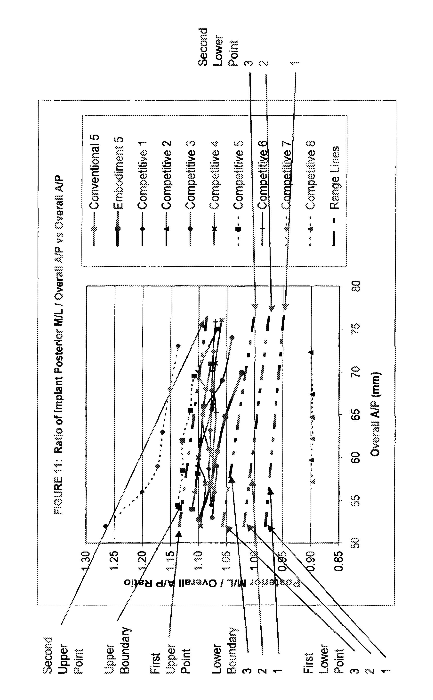
D00013
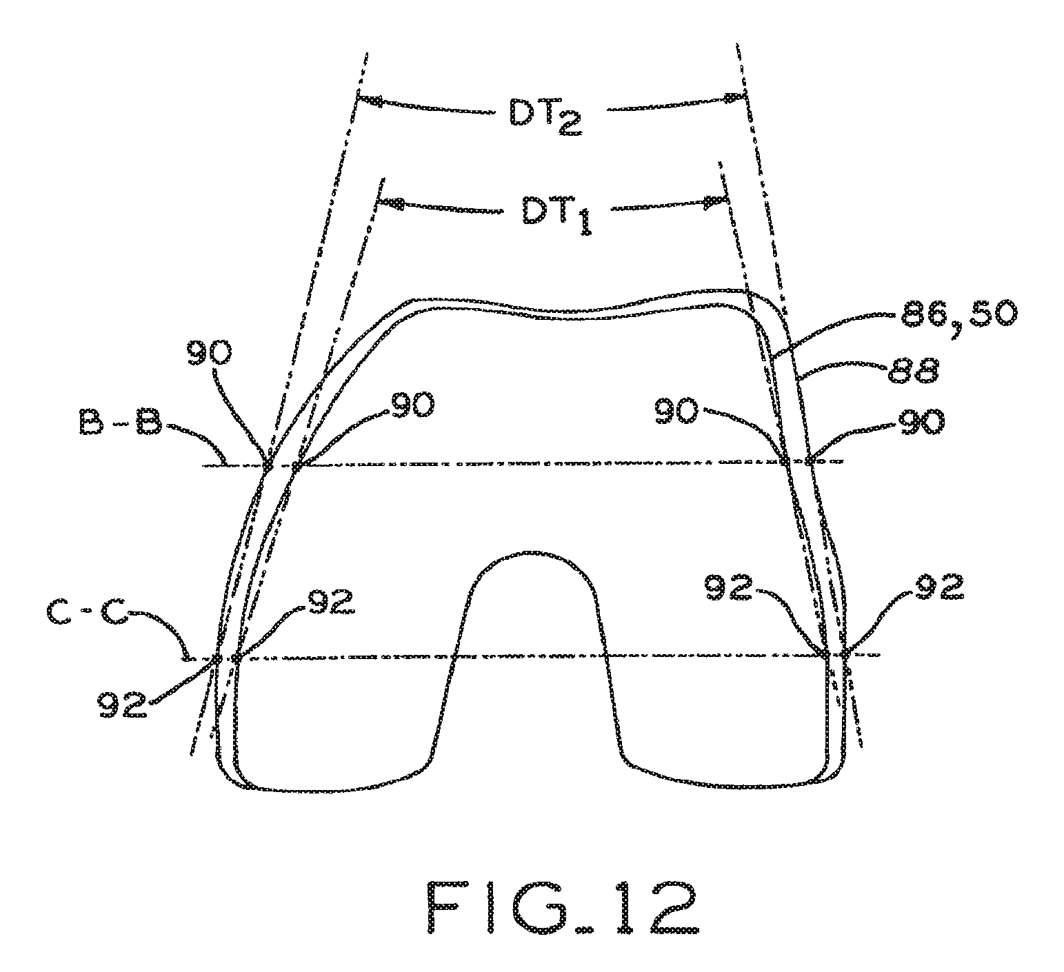
D00014
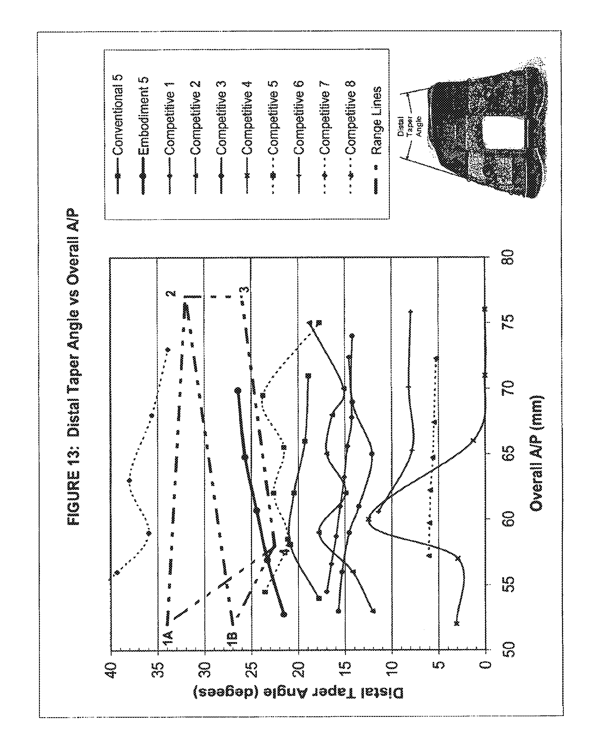
D00015
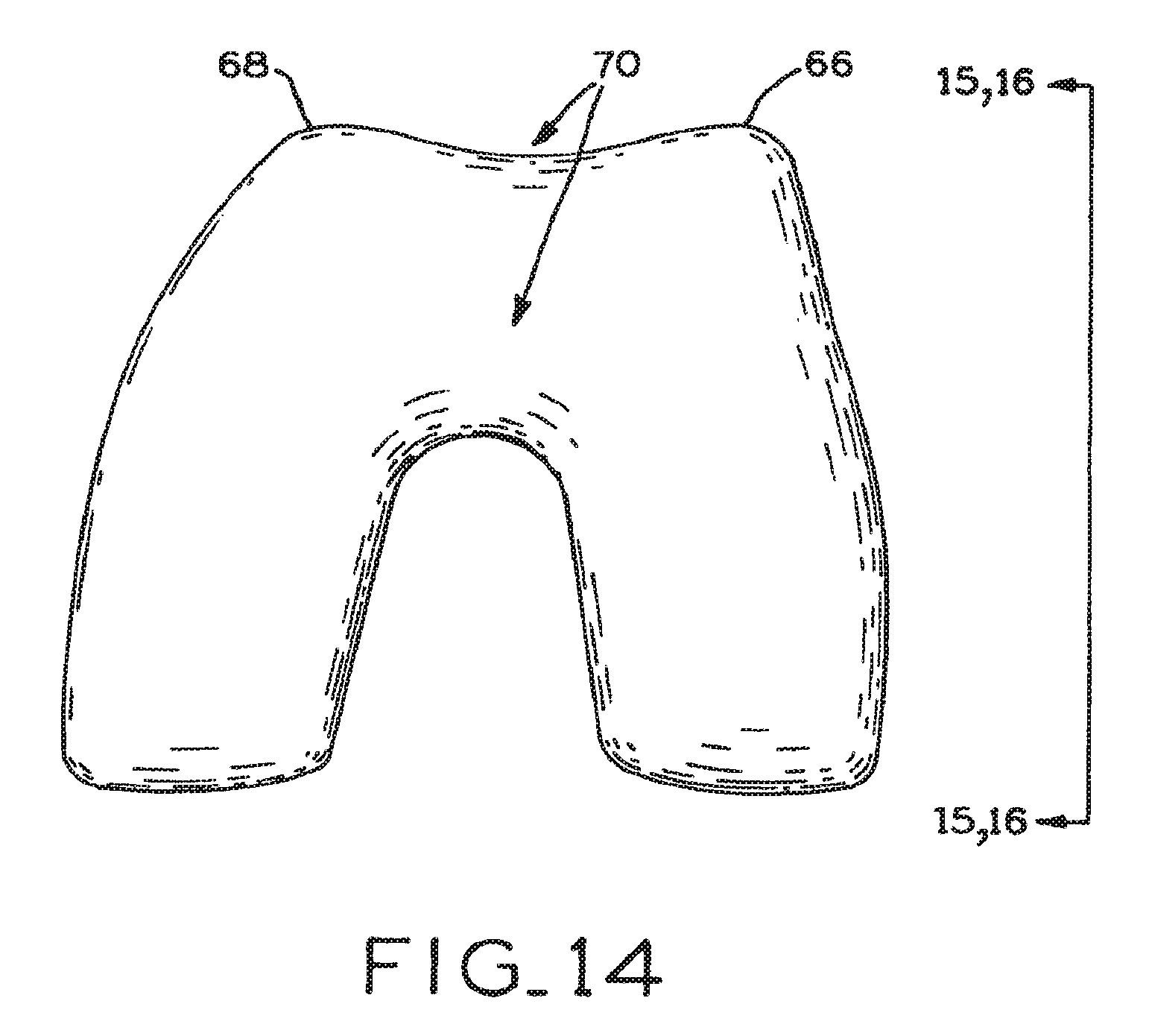
D00016
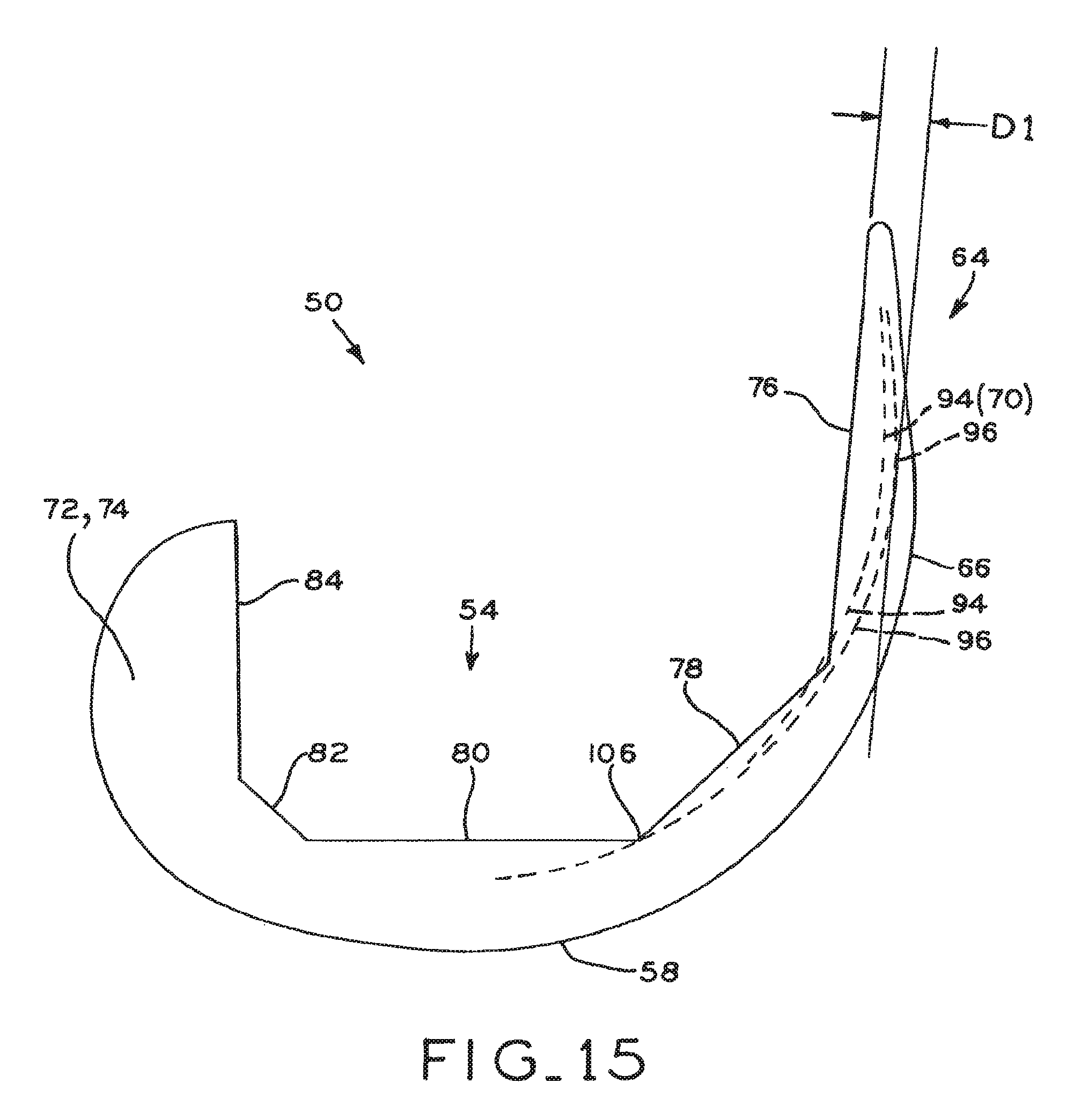
D00017
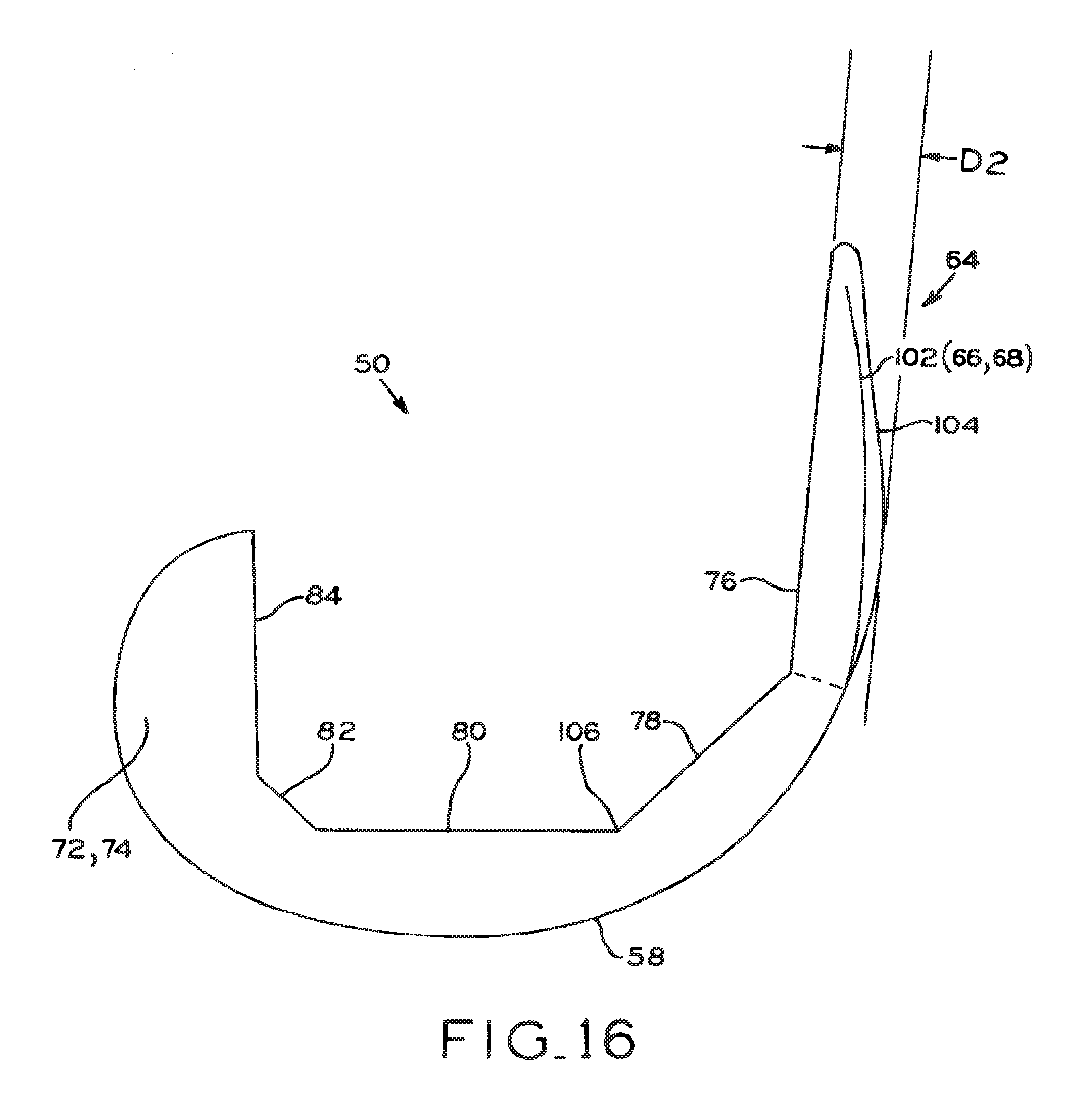
D00018
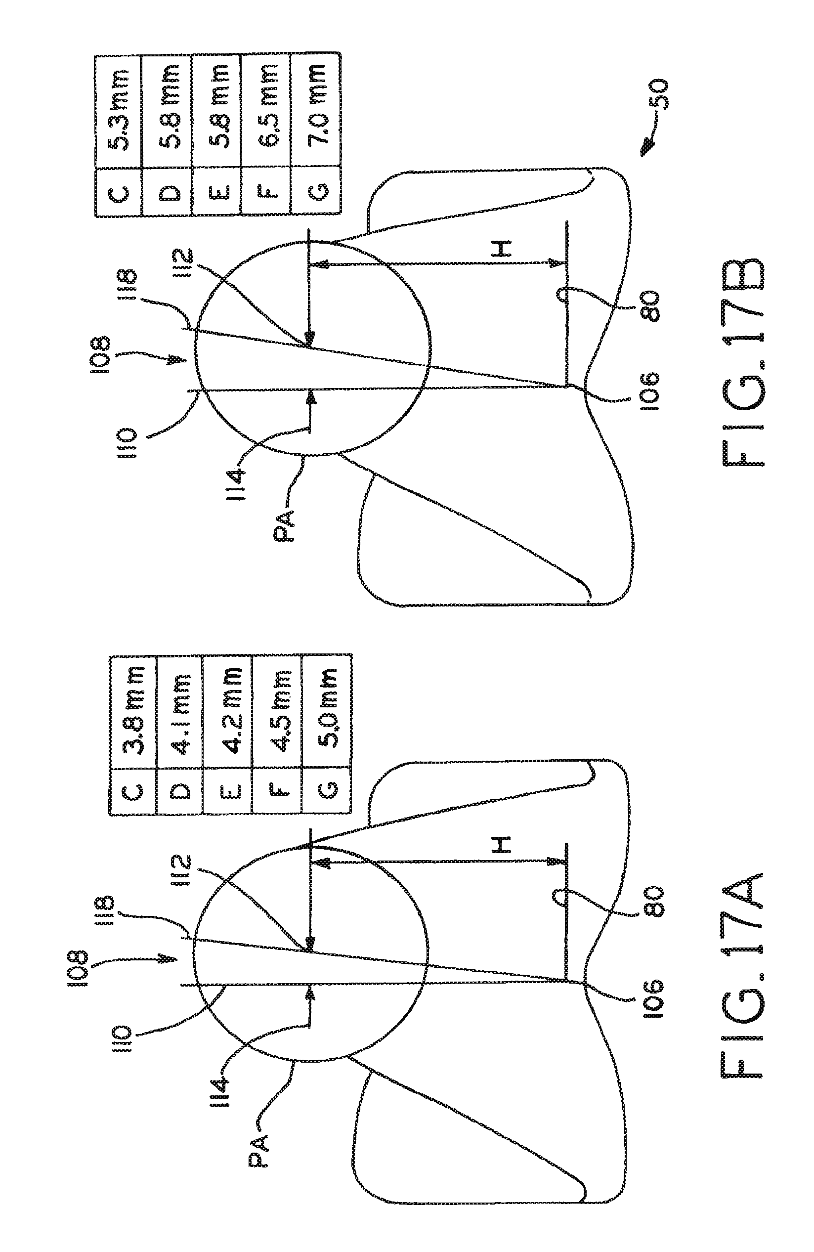
D00019
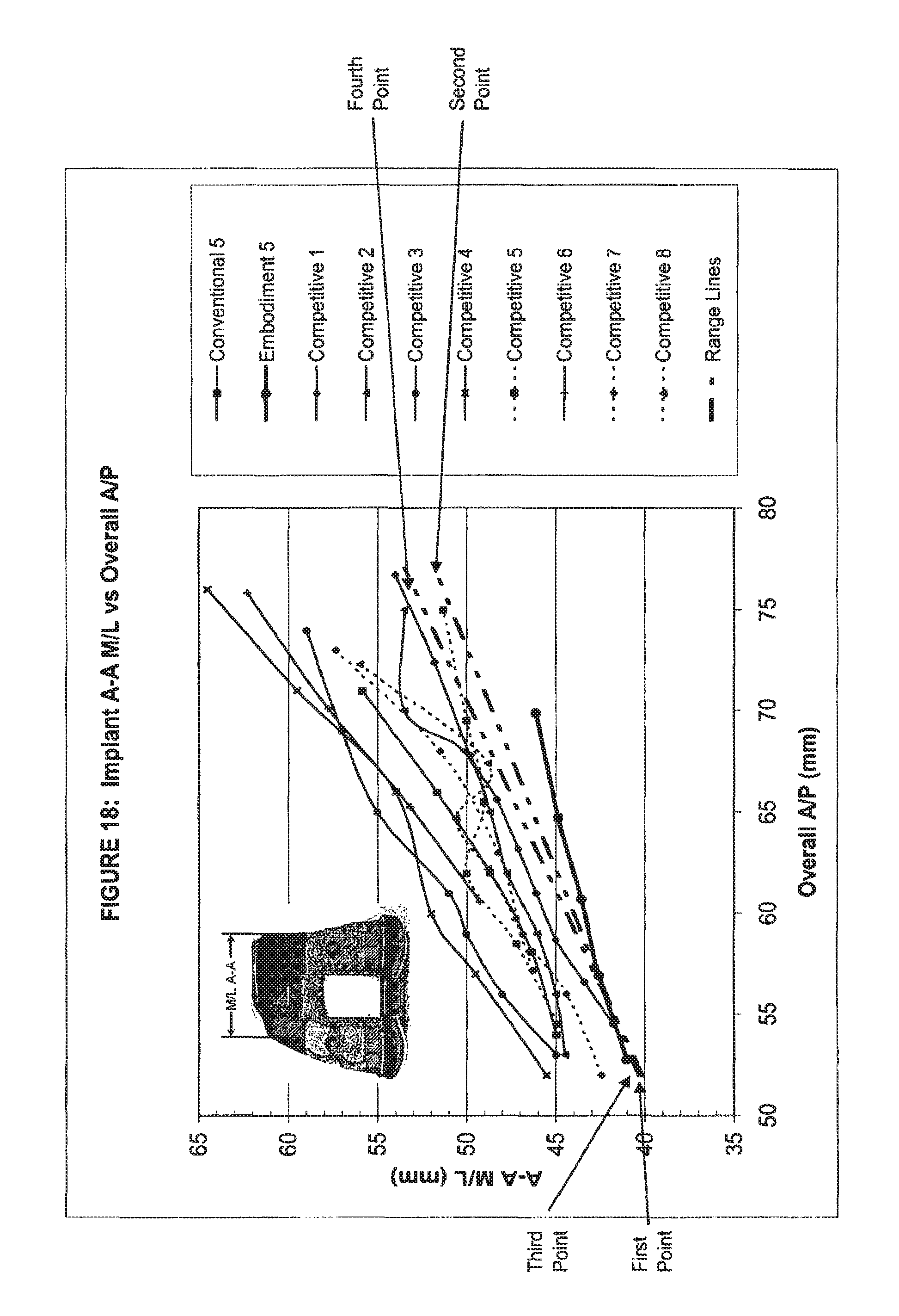
D00020

XML
uspto.report is an independent third-party trademark research tool that is not affiliated, endorsed, or sponsored by the United States Patent and Trademark Office (USPTO) or any other governmental organization. The information provided by uspto.report is based on publicly available data at the time of writing and is intended for informational purposes only.
While we strive to provide accurate and up-to-date information, we do not guarantee the accuracy, completeness, reliability, or suitability of the information displayed on this site. The use of this site is at your own risk. Any reliance you place on such information is therefore strictly at your own risk.
All official trademark data, including owner information, should be verified by visiting the official USPTO website at www.uspto.gov. This site is not intended to replace professional legal advice and should not be used as a substitute for consulting with a legal professional who is knowledgeable about trademark law.