Delivery systems with tethers for prosthetic heart valve devices and associated methods
McLean O
U.S. patent number 10,433,961 [Application Number 15/490,024] was granted by the patent office on 2019-10-08 for delivery systems with tethers for prosthetic heart valve devices and associated methods. This patent grant is currently assigned to Twelve, Inc.. The grantee listed for this patent is Twelve, Inc.. Invention is credited to Matthew McLean.


View All Diagrams
| United States Patent | 10,433,961 |
| McLean | October 8, 2019 |
Delivery systems with tethers for prosthetic heart valve devices and associated methods
Abstract
Delivery systems with tethers for prosthetic heart valve devices and associated methods are disclosed herein. A delivery system configured in accordance with embodiments of the present technology can include, for example, an elongated catheter body, a capsule carried by the elongated catheter body and carrying a prosthetic heart valve device, and a cinching member slidably disposed within the capsule. The delivery system can further include a plurality of tether elements coupled to the prosthetic device and extending through the cinching member and the catheter body. Retraction of the tether elements can urge at least a portion of the prosthetic device into a distal end portion of the cinching member to resheathe at least a portion of the prosthetic device and allow repositioning of the prosthetic device relative to the native valve after a portion of the prosthetic device has contacted tissue of a native valve.
| Inventors: | McLean; Matthew (San Francisco, CA) | ||||||||||
|---|---|---|---|---|---|---|---|---|---|---|---|
| Applicant: |
|
||||||||||
| Assignee: | Twelve, Inc. (Redwood City,
CA) |
||||||||||
| Family ID: | 62111261 | ||||||||||
| Appl. No.: | 15/490,024 | ||||||||||
| Filed: | April 18, 2017 |
Prior Publication Data
| Document Identifier | Publication Date | |
|---|---|---|
| US 20180296339 A1 | Oct 18, 2018 | |
| Current U.S. Class: | 1/1 |
| Current CPC Class: | A61F 2/2436 (20130101); A61F 2/2409 (20130101); A61F 2/2439 (20130101); A61F 2/243 (20130101); A61F 2250/0069 (20130101); A61F 2002/9534 (20130101); A61F 2220/0016 (20130101) |
| Current International Class: | A61F 2/24 (20060101); A61F 2/95 (20130101) |
References Cited [Referenced By]
U.S. Patent Documents
| 3526219 | September 1970 | Balanmuth |
| 3565062 | February 1971 | Kuris |
| 3589363 | June 1971 | Banko et al. |
| 3667474 | June 1972 | Lapkin et al. |
| 3823717 | July 1974 | Pohlman et al. |
| 3861391 | January 1975 | Antonevich et al. |
| 3896811 | July 1975 | Storz |
| 4042979 | August 1977 | Angell |
| 4188952 | February 1980 | Loschilov et al. |
| 4431006 | February 1984 | Trimmer et al. |
| 4445509 | May 1984 | Auth |
| 4484579 | November 1984 | Meno et al. |
| 4490859 | January 1985 | Black et al. |
| 4587958 | May 1986 | Noguchi et al. |
| 4589419 | May 1986 | Laughlin et al. |
| 4602911 | July 1986 | Ahmadi et al. |
| 4646736 | March 1987 | Auth |
| 4692139 | September 1987 | Stiles |
| 4747821 | May 1988 | Kensey et al. |
| 4750902 | June 1988 | Wuchinich et al. |
| 4777951 | October 1988 | Cribier et al. |
| 4787388 | November 1988 | Hofmann |
| 4796629 | January 1989 | Grayzel |
| 4808153 | February 1989 | Parisi |
| 4819751 | April 1989 | Shimada et al. |
| 4841977 | June 1989 | Griffith et al. |
| 4870953 | October 1989 | DonMicheal et al. |
| 4878495 | November 1989 | Grayzel |
| 4898575 | February 1990 | Fischell et al. |
| 4909252 | March 1990 | Goldberger |
| 4919133 | April 1990 | Chiang |
| 4920954 | May 1990 | Alliger et al. |
| 4936281 | June 1990 | Stasz |
| 4960411 | October 1990 | Buchbinder |
| 4986830 | January 1991 | Owens et al. |
| 4990134 | February 1991 | Auth |
| 5058570 | October 1991 | Idemoto et al. |
| 5069664 | December 1991 | Guess et al. |
| 5076276 | December 1991 | Sakurai et al. |
| 5106302 | April 1992 | Farzin-Nia et al. |
| 5248296 | September 1993 | Alliger |
| 5267954 | December 1993 | Nita |
| 5269291 | December 1993 | Carter |
| 5295958 | March 1994 | Shturman |
| 5304115 | April 1994 | Pflueger et al. |
| 5314407 | May 1994 | Auth et al. |
| 5318014 | June 1994 | Carter |
| 5332402 | July 1994 | Teitelbaum |
| 5344426 | September 1994 | Lau et al. |
| 5352199 | October 1994 | Tower |
| 5356418 | October 1994 | Shturman |
| 5397293 | March 1995 | Alliger et al. |
| 5411552 | May 1995 | Andersen et al. |
| 5443446 | August 1995 | Shturman |
| 5449373 | September 1995 | Pinchasik et al. |
| 5489297 | February 1996 | Duran |
| 5584879 | December 1996 | Reimold et al. |
| 5609151 | March 1997 | Mulier et al. |
| 5626603 | May 1997 | Venturelli et al. |
| 5656036 | August 1997 | Palmaz |
| 5662671 | September 1997 | Barbut et al. |
| 5681336 | October 1997 | Clement et al. |
| 5695507 | December 1997 | Auth et al. |
| 5725494 | March 1998 | Brisken |
| 5782931 | July 1998 | Yang et al. |
| 5817101 | October 1998 | Fiedler |
| 5827229 | October 1998 | Auth et al. |
| 5827321 | October 1998 | Roubin et al. |
| 5840081 | November 1998 | Andersen et al. |
| 5853422 | December 1998 | Huebsch et al. |
| 5855601 | January 1999 | Bessler et al. |
| 5868781 | February 1999 | Killion |
| 5873811 | February 1999 | Wang et al. |
| 5904679 | May 1999 | Clayman |
| 5957882 | September 1999 | Nita et al. |
| 5972004 | October 1999 | Williamson, IV et al. |
| 5989208 | November 1999 | Nita |
| 5989280 | November 1999 | Euteneuer et al. |
| 6047700 | April 2000 | Eggers et al. |
| 6056759 | May 2000 | Fiedler |
| 6085754 | July 2000 | Alferness et al. |
| 6113608 | September 2000 | Monroe et al. |
| RE36939 | October 2000 | Tachibana et al. |
| 6129734 | October 2000 | Shturman et al. |
| 6132444 | October 2000 | Shturman et al. |
| 6168579 | January 2001 | Tsugita |
| 6217595 | April 2001 | Shturman et al. |
| 6254635 | July 2001 | Schroeder et al. |
| 6295712 | October 2001 | Shturman et al. |
| 6306414 | October 2001 | Koike |
| 6321109 | November 2001 | Ben-Haim et al. |
| 6402679 | June 2002 | Mortier et al. |
| 6423032 | July 2002 | Parodi |
| 6425916 | July 2002 | Garrison et al. |
| 6440164 | August 2002 | DiMatteo et al. |
| 6454737 | September 2002 | Nita et al. |
| 6454757 | September 2002 | Nita et al. |
| 6454799 | September 2002 | Schreck |
| 6458153 | October 2002 | Bailey et al. |
| 6461382 | October 2002 | Cao |
| 6494890 | December 2002 | Shturman et al. |
| 6494891 | December 2002 | Cornish et al. |
| 6505080 | January 2003 | Sutton |
| 6530952 | March 2003 | Vesely |
| 6540782 | April 2003 | Snyders |
| 6562067 | May 2003 | Mathis |
| 6565588 | May 2003 | Clement et al. |
| 6569196 | May 2003 | Vesely |
| 6579308 | June 2003 | Jansen et al. |
| 6582462 | June 2003 | Andersen et al. |
| 6595912 | July 2003 | Lau et al. |
| 6605109 | August 2003 | Fiedler |
| 6616689 | September 2003 | Ainsworth et al. |
| 6623452 | September 2003 | Chien et al. |
| 6638288 | October 2003 | Shturman et al. |
| 6648854 | November 2003 | Patterson et al. |
| 6689086 | February 2004 | Nita et al. |
| 6702748 | March 2004 | Nita et al. |
| 6730121 | May 2004 | Ortiz et al. |
| 6746463 | June 2004 | Schwartz |
| 6811801 | November 2004 | Nguyen et al. |
| 6818001 | November 2004 | Wulfman et al. |
| 6843797 | January 2005 | Nash et al. |
| 6852118 | February 2005 | Shturman et al. |
| 6855123 | February 2005 | Nita |
| 6869439 | March 2005 | White et al. |
| 6951571 | October 2005 | Srivastava |
| 6986775 | January 2006 | Morales et al. |
| 7018404 | March 2006 | Holmberg et al. |
| 7052487 | May 2006 | Cohn et al. |
| 7077861 | July 2006 | Spence |
| 7125420 | October 2006 | Rourke et al. |
| 7186264 | March 2007 | Liddicoat et al. |
| 7261732 | August 2007 | Justino |
| 7296577 | November 2007 | Lashinski et al. |
| 7381218 | June 2008 | Schreck |
| 7404824 | July 2008 | Webler et al. |
| 7442204 | October 2008 | Schwammenthal et al. |
| 7473275 | January 2009 | Marquez |
| 7510575 | March 2009 | Spenser et al. |
| 7585321 | September 2009 | Cribier |
| 7588582 | September 2009 | Starksen et al. |
| 7621948 | November 2009 | Herrmann et al. |
| 7708775 | May 2010 | Rowe et al. |
| 7748389 | July 2010 | Salahieh et al. |
| 7753922 | July 2010 | Starksen |
| 7753949 | July 2010 | Lamphere et al. |
| 7803168 | September 2010 | Gifford et al. |
| 7857845 | December 2010 | Stacchino et al. |
| 7896915 | March 2011 | Guyenot et al. |
| 7942928 | May 2011 | Webler et al. |
| 8002826 | August 2011 | Seguin |
| 8052750 | November 2011 | Tuval et al. |
| 8062355 | November 2011 | Figulla et al. |
| 8109996 | February 2012 | Stacchino et al. |
| 8114154 | February 2012 | Righini et al. |
| 8252051 | August 2012 | Chau et al. |
| 8398704 | March 2013 | Straubinger et al. |
| 8403981 | March 2013 | Forster et al. |
| 8403983 | March 2013 | Quadri et al. |
| 8414643 | April 2013 | Tuval et al. |
| 8449599 | May 2013 | Chau et al. |
| 8496671 | July 2013 | Hausen |
| 8512252 | August 2013 | Ludomirsky et al. |
| 8518107 | August 2013 | Tsukashima et al. |
| 8523883 | September 2013 | Saadat |
| 8532352 | September 2013 | Ionasec et al. |
| 8540767 | September 2013 | Zhang |
| 8545551 | October 2013 | Loulmet |
| 8551161 | October 2013 | Dolan |
| 8579788 | November 2013 | Orejola |
| 8579964 | November 2013 | Lane et al. |
| 8585755 | November 2013 | Chau et al. |
| 8597347 | December 2013 | Maurer et al. |
| 8597348 | December 2013 | Rowe et al. |
| 8608796 | December 2013 | Matheny |
| 8608797 | December 2013 | Gross et al. |
| 8623077 | January 2014 | Cohn |
| 8628566 | January 2014 | Eberhardt et al. |
| 8632585 | January 2014 | Seguin et al. |
| 8632586 | January 2014 | Spenser et al. |
| 8634935 | January 2014 | Gaudiani |
| 8647254 | February 2014 | Callas et al. |
| 8652203 | February 2014 | Quadri et al. |
| 8652204 | February 2014 | Quill et al. |
| 8657872 | February 2014 | Seguin |
| 8672998 | March 2014 | Lichtenstein et al. |
| 8673001 | March 2014 | Cartledge et al. |
| 8679176 | March 2014 | Matheny |
| 8685086 | April 2014 | Navia et al. |
| 8688234 | April 2014 | Zhu et al. |
| 8690858 | April 2014 | Machold et al. |
| 8709074 | April 2014 | Solem et al. |
| 8712133 | April 2014 | Guhring et al. |
| 8715160 | May 2014 | Raman et al. |
| 8721665 | May 2014 | Oz et al. |
| 8721718 | May 2014 | Kassab |
| 8740918 | June 2014 | Seguin |
| 8747460 | June 2014 | Tuval et al. |
| 8758431 | June 2014 | Orlov et al. |
| 8758432 | June 2014 | Solem |
| 8771292 | July 2014 | Allen et al. |
| 8771345 | July 2014 | Tuval et al. |
| 8771346 | July 2014 | Tuval et al. |
| 8777991 | July 2014 | Zarbatany et al. |
| 8778016 | July 2014 | Janovsky et al. |
| 8781580 | July 2014 | Hedberg et al. |
| 8784482 | July 2014 | Rahdert et al. |
| 8792699 | July 2014 | Guetter et al. |
| 8795356 | August 2014 | Quadri et al. |
| 8801779 | August 2014 | Seguin et al. |
| 8808356 | August 2014 | Braido et al. |
| 8808366 | August 2014 | Braido et al. |
| 8812431 | August 2014 | Voigt et al. |
| 8828043 | September 2014 | Chambers |
| 8845717 | September 2014 | Khairkhahan et al. |
| 8845723 | September 2014 | Spence et al. |
| 8852213 | October 2014 | Gammie et al. |
| 8852272 | October 2014 | Gross et al. |
| 8858622 | October 2014 | Machold et al. |
| 8859724 | October 2014 | Meier et al. |
| 8864822 | October 2014 | Spence et al. |
| 8870936 | October 2014 | Rowe |
| 8870948 | October 2014 | Erzberger et al. |
| 8870949 | October 2014 | Rowe |
| 8894702 | November 2014 | Quadri et al. |
| 8900295 | December 2014 | Migliazza et al. |
| 8926694 | January 2015 | Costello |
| 8932348 | January 2015 | Solem et al. |
| 8951285 | February 2015 | Sugimoto et al. |
| 8961597 | February 2015 | Subramanian et al. |
| 8968393 | March 2015 | Rothstein |
| 8968395 | March 2015 | Hauser et al. |
| 8974445 | March 2015 | Warnking et al. |
| 8979922 | March 2015 | Jayasinghe et al. |
| 8979923 | March 2015 | Spence et al. |
| 8986370 | March 2015 | Annest |
| 8986376 | March 2015 | Solem |
| 8992604 | March 2015 | Gross et al. |
| 9011522 | April 2015 | Annest |
| 9011523 | April 2015 | Seguin |
| 9017399 | April 2015 | Gross et al. |
| 9023098 | May 2015 | Kuehn |
| 9023100 | May 2015 | Quadri et al. |
| 9050188 | June 2015 | Schweich, Jr. et al. |
| 9066800 | June 2015 | Clague et al. |
| 9084676 | July 2015 | Chau et al. |
| 9095433 | August 2015 | Lutter et al. |
| 9119713 | September 2015 | Board et al. |
| 9132009 | September 2015 | Hacohen et al. |
| 9138312 | September 2015 | Tuval et al. |
| 9138313 | September 2015 | McGuckin, Jr. et al. |
| 9180005 | November 2015 | Lashinski et al. |
| 9192466 | November 2015 | Kovalsky et al. |
| 9192471 | November 2015 | Bolling |
| 9232942 | January 2016 | Seguin et al. |
| 9232999 | January 2016 | Maurer et al. |
| 9241790 | January 2016 | Lane et al. |
| 9248014 | February 2016 | Lane et al. |
| 9254192 | February 2016 | Lutter et al. |
| 9271833 | March 2016 | Kim et al. |
| 9289291 | March 2016 | Gorman, III et al. |
| 9289297 | March 2016 | Wilson et al. |
| 9295547 | March 2016 | Costello et al. |
| 9301836 | April 2016 | Buchbinder et al. |
| 9308087 | April 2016 | Lane et al. |
| 9326850 | May 2016 | Venkatasubramanian |
| 9339378 | May 2016 | Quadri et al. |
| 9339379 | May 2016 | Quadri et al. |
| 9339380 | May 2016 | Quadri et al. |
| 9339382 | May 2016 | Tabor et al. |
| 9358108 | June 2016 | Bortlein et al. |
| 9387075 | July 2016 | Bortlein et al. |
| 9387078 | July 2016 | Gross et al. |
| 9393111 | July 2016 | Ma et al. |
| 9629719 | April 2017 | Rothstein et al. |
| 9675454 | June 2017 | Vidlund et al. |
| 9681951 | June 2017 | Ratz et al. |
| 9687342 | June 2017 | Figulla et al. |
| 9687343 | June 2017 | Bortlein et al. |
| 9693859 | July 2017 | Braido et al. |
| 9693862 | July 2017 | Campbell et al. |
| 9694121 | July 2017 | Alexander et al. |
| 9700409 | July 2017 | Braido et al. |
| 9700411 | July 2017 | Klima et al. |
| 9730791 | August 2017 | Ratz et al. |
| 9730794 | August 2017 | Carpentier et al. |
| 9750605 | September 2017 | Ganesan et al. |
| 9750606 | September 2017 | Ganesan et al. |
| 9750607 | September 2017 | Ganesan et al. |
| 9763657 | September 2017 | Hacohen et al. |
| 9763658 | September 2017 | Eigler et al. |
| 9763782 | September 2017 | Solem et al. |
| 9770328 | September 2017 | Macoviak et al. |
| 9788931 | October 2017 | Giordano et al. |
| 9801717 | October 2017 | Edquist et al. |
| 9827092 | November 2017 | Vidlund et al. |
| 9827101 | November 2017 | Solem et al. |
| 9833313 | December 2017 | Board et al. |
| 9833315 | December 2017 | Vidlund et al. |
| 9839511 | December 2017 | Ma et al. |
| 9844435 | December 2017 | Eidenschink |
| 9848880 | December 2017 | Coleman et al. |
| 9848983 | December 2017 | Lashinski et al. |
| 9861477 | January 2018 | Backus et al. |
| 9861480 | January 2018 | Zakai et al. |
| 2001/0021872 | September 2001 | Bailey et al. |
| 2001/0049492 | December 2001 | Frazier et al. |
| 2002/0007219 | January 2002 | Merrill et al. |
| 2002/0013571 | January 2002 | Goldfarb et al. |
| 2002/0072792 | June 2002 | Burgermeister et al. |
| 2002/0082637 | June 2002 | Lumauig |
| 2002/0099439 | July 2002 | Schwartz et al. |
| 2002/0138138 | September 2002 | Yang |
| 2002/0151970 | October 2002 | Garrison et al. |
| 2002/0173841 | November 2002 | Ortiz et al. |
| 2003/0120340 | June 2003 | Liska et al. |
| 2003/0139689 | July 2003 | Shturman et al. |
| 2004/0006358 | January 2004 | Wulfman et al. |
| 2004/0039412 | February 2004 | Isshiki et al. |
| 2004/0044350 | March 2004 | Martin et al. |
| 2004/0057955 | March 2004 | O'Brien et al. |
| 2004/0082910 | April 2004 | Constantz et al. |
| 2004/0092858 | May 2004 | Wilson et al. |
| 2004/0092962 | May 2004 | Thornton et al. |
| 2004/0092989 | May 2004 | Wilson et al. |
| 2004/0106989 | June 2004 | Wilson et al. |
| 2004/0117009 | June 2004 | Cali et al. |
| 2004/0122510 | June 2004 | Sarac |
| 2004/0127979 | July 2004 | Wilson et al. |
| 2004/0127982 | July 2004 | Machold et al. |
| 2004/0186558 | September 2004 | Pavcnik et al. |
| 2004/0199191 | October 2004 | Schwartz |
| 2004/0220655 | November 2004 | Swanson |
| 2004/0230117 | November 2004 | Tosaya et al. |
| 2004/0230212 | November 2004 | Wulfman |
| 2004/0230213 | November 2004 | Wulfman et al. |
| 2004/0243162 | December 2004 | Wulfman et al. |
| 2005/0007219 | January 2005 | Ma et al. |
| 2005/0075662 | April 2005 | Pedersen et al. |
| 2005/0075720 | April 2005 | Nguyen et al. |
| 2005/0075727 | April 2005 | Wheatley |
| 2005/0107661 | May 2005 | Lau et al. |
| 2005/0137682 | June 2005 | Justino |
| 2005/0137690 | June 2005 | Salahieh et al. |
| 2005/0137691 | June 2005 | Salahieh et al. |
| 2005/0137695 | June 2005 | Salahieh et al. |
| 2005/0137697 | June 2005 | Salahieh et al. |
| 2005/0137698 | June 2005 | Salahieh et al. |
| 2005/0137700 | June 2005 | Spence et al. |
| 2005/0137701 | June 2005 | Salahieh et al. |
| 2005/0137702 | June 2005 | Haug et al. |
| 2005/0228477 | October 2005 | Grainger et al. |
| 2005/0267523 | December 2005 | Devellian et al. |
| 2005/0273135 | December 2005 | Chanduszko |
| 2006/0058872 | March 2006 | Salahieh et al. |
| 2006/0106456 | May 2006 | Machold et al. |
| 2006/0149360 | July 2006 | Schwammenthal et al. |
| 2006/0167543 | July 2006 | Bailey et al. |
| 2006/0195183 | August 2006 | Navia et al. |
| 2006/0253191 | November 2006 | Salahieh et al. |
| 2006/0287719 | December 2006 | Rowe et al. |
| 2007/0056346 | March 2007 | Spenser et al. |
| 2007/0061010 | March 2007 | Hauser et al. |
| 2007/0073391 | March 2007 | Bourang et al. |
| 2007/0078302 | April 2007 | Ortiz et al. |
| 2007/0088431 | April 2007 | Bourang et al. |
| 2007/0142906 | June 2007 | Figulla et al. |
| 2007/0173932 | July 2007 | Cali et al. |
| 2008/0071369 | March 2008 | Tuval et al. |
| 2008/0082166 | April 2008 | Styrc et al. |
| 2008/0103586 | May 2008 | Styrc et al. |
| 2008/0140189 | June 2008 | Nguyen et al. |
| 2008/0208332 | August 2008 | Lamphere et al. |
| 2008/0221672 | September 2008 | Lamphere et al. |
| 2008/0234728 | September 2008 | Starksen et al. |
| 2008/0243245 | October 2008 | Thambar et al. |
| 2008/0243246 | October 2008 | Ryan et al. |
| 2009/0054969 | February 2009 | Salahieh et al. |
| 2009/0076586 | March 2009 | Hauser et al. |
| 2009/0076598 | March 2009 | Salahieh et al. |
| 2009/0093670 | April 2009 | Annest et al. |
| 2009/0157174 | June 2009 | Yoganathan et al. |
| 2009/0164006 | June 2009 | Seguin et al. |
| 2009/0198315 | August 2009 | Boudjemline |
| 2009/0216312 | August 2009 | Straubinger et al. |
| 2009/0240320 | September 2009 | Tuval et al. |
| 2009/0259292 | October 2009 | Bonhoeffer |
| 2009/0259306 | October 2009 | Rowe |
| 2009/0264997 | October 2009 | Salahieh et al. |
| 2009/0276040 | November 2009 | Rowe et al. |
| 2009/0281609 | November 2009 | Benichou et al. |
| 2009/0281618 | November 2009 | Hill et al. |
| 2009/0292350 | November 2009 | Eberhardt et al. |
| 2009/0306768 | December 2009 | Quadri |
| 2009/0319037 | December 2009 | Rowe et al. |
| 2009/0319038 | December 2009 | Gurskis et al. |
| 2010/0016958 | January 2010 | St. Goar et al. |
| 2010/0023115 | January 2010 | Robaina et al. |
| 2010/0023117 | January 2010 | Yoganathan et al. |
| 2010/0030330 | February 2010 | Bobo et al. |
| 2010/0049313 | February 2010 | Alon et al. |
| 2010/0076548 | March 2010 | Konno |
| 2010/0082094 | April 2010 | Quadri et al. |
| 2010/0094411 | April 2010 | Tuval et al. |
| 2010/0121436 | May 2010 | Tuval et al. |
| 2010/0185275 | July 2010 | Richter et al. |
| 2010/0217382 | August 2010 | Chau et al. |
| 2010/0249915 | September 2010 | Zhang |
| 2010/0249923 | September 2010 | Alkhatib et al. |
| 2010/0298929 | November 2010 | Thornton et al. |
| 2010/0298931 | November 2010 | Quadri et al. |
| 2010/0312333 | December 2010 | Navia et al. |
| 2010/0324554 | December 2010 | Gifford et al. |
| 2011/0004296 | January 2011 | Lutter et al. |
| 2011/0015722 | January 2011 | Hauser et al. |
| 2011/0022166 | January 2011 | Dahlgren et al. |
| 2011/0029071 | February 2011 | Zlotnick et al. |
| 2011/0029072 | February 2011 | Gabbay |
| 2011/0040374 | February 2011 | Goetz et al. |
| 2011/0040375 | February 2011 | Letac et al. |
| 2011/0066231 | March 2011 | Cartledge et al. |
| 2011/0066233 | March 2011 | Thornton et al. |
| 2011/0112632 | May 2011 | Chau et al. |
| 2011/0137397 | June 2011 | Chau et al. |
| 2011/0137409 | June 2011 | Yang et al. |
| 2011/0137410 | June 2011 | Hacohen |
| 2011/0153008 | June 2011 | Marchand et al. |
| 2011/0172784 | July 2011 | Richter et al. |
| 2011/0184512 | July 2011 | Webler et al. |
| 2011/0208293 | August 2011 | Tabor |
| 2011/0224785 | September 2011 | Hacohen |
| 2011/0319988 | December 2011 | Schankereli et al. |
| 2012/0022639 | January 2012 | Hacohen et al. |
| 2012/0035703 | February 2012 | Lutter et al. |
| 2012/0035713 | February 2012 | Lutter et al. |
| 2012/0053680 | March 2012 | Bolling et al. |
| 2012/0053682 | March 2012 | Kovalsky et al. |
| 2012/0078347 | March 2012 | Braido et al. |
| 2012/0078360 | March 2012 | Rafiee |
| 2012/0101571 | April 2012 | Thambar et al. |
| 2012/0165930 | June 2012 | Gifford, III et al. |
| 2012/0179239 | July 2012 | Quadri |
| 2012/0179244 | July 2012 | Schankereli et al. |
| 2012/0203336 | August 2012 | Annest |
| 2012/0283824 | November 2012 | Lutter et al. |
| 2013/0172978 | July 2013 | Vidlund et al. |
| 2013/0190860 | July 2013 | Sundt, III |
| 2013/0190861 | July 2013 | Chau et al. |
| 2013/0197354 | August 2013 | Maschke et al. |
| 2013/0197630 | August 2013 | Azarnoush |
| 2013/0204356 | August 2013 | Dwork et al. |
| 2013/0204358 | August 2013 | Matheny |
| 2013/0226289 | August 2013 | Shaolian et al. |
| 2013/0226290 | August 2013 | Yellin et al. |
| 2013/0231735 | September 2013 | Deem et al. |
| 2013/0238089 | September 2013 | Lichtenstein et al. |
| 2013/0244927 | September 2013 | Lal et al. |
| 2013/0253641 | September 2013 | Lattouf |
| 2013/0253642 | September 2013 | Brecker |
| 2013/0253643 | September 2013 | Rolando et al. |
| 2013/0259337 | October 2013 | Guhring et al. |
| 2013/0261737 | October 2013 | Costello |
| 2013/0261738 | October 2013 | Clague et al. |
| 2013/0261739 | October 2013 | Kuehn |
| 2013/0261741 | October 2013 | Accola |
| 2013/0268066 | October 2013 | Rowe |
| 2013/0274870 | October 2013 | Lombardi et al. |
| 2013/0282059 | October 2013 | Ketai et al. |
| 2013/0282060 | October 2013 | Tuval |
| 2013/0282110 | October 2013 | Schweich, Jr. et al. |
| 2013/0289642 | October 2013 | Hedberg et al. |
| 2013/0289717 | October 2013 | Solem |
| 2013/0289718 | October 2013 | Tsukashima et al. |
| 2013/0296851 | November 2013 | Boronyak et al. |
| 2013/0296999 | November 2013 | Burriesci et al. |
| 2013/0304180 | November 2013 | Green et al. |
| 2013/0304181 | November 2013 | Green et al. |
| 2013/0304197 | November 2013 | Buchbinder et al. |
| 2013/0304198 | November 2013 | Solem |
| 2013/0304200 | November 2013 | Mclean et al. |
| 2013/0309292 | November 2013 | Andersen |
| 2013/0310436 | November 2013 | Lowes et al. |
| 2013/0310925 | November 2013 | Eliasen et al. |
| 2013/0310928 | November 2013 | Morriss et al. |
| 2013/0317603 | November 2013 | Mclean et al. |
| 2013/0325110 | December 2013 | Khalil et al. |
| 2013/0325114 | December 2013 | Mclean et al. |
| 2013/0331864 | December 2013 | Jelich et al. |
| 2013/0338684 | December 2013 | Hausen |
| 2013/0338763 | December 2013 | Rowe et al. |
| 2013/0345797 | December 2013 | Dahlgren et al. |
| 2013/0345803 | December 2013 | Bergheim, III |
| 2014/0005778 | January 2014 | Buchbinder et al. |
| 2014/0018906 | January 2014 | Rafiee |
| 2014/0018913 | January 2014 | Cartledge et al. |
| 2014/0023261 | January 2014 | Watanabe et al. |
| 2014/0025164 | January 2014 | Montorfano et al. |
| 2014/0031928 | January 2014 | Murphy et al. |
| 2014/0046219 | February 2014 | Sauter et al. |
| 2014/0046436 | February 2014 | Kheradvar |
| 2014/0052237 | February 2014 | Lane et al. |
| 2014/0052240 | February 2014 | Zhang |
| 2014/0056906 | February 2014 | Yue et al. |
| 2014/0066895 | March 2014 | Kipperman |
| 2014/0067048 | March 2014 | Chau et al. |
| 2014/0067052 | March 2014 | Chau et al. |
| 2014/0067054 | March 2014 | Chau et al. |
| 2014/0088071 | March 2014 | Nakai et al. |
| 2014/0088680 | March 2014 | Costello et al. |
| 2014/0088693 | March 2014 | Seguin et al. |
| 2014/0088695 | March 2014 | Figulla et al. |
| 2014/0094906 | April 2014 | Spence et al. |
| 2014/0107775 | April 2014 | Hjelle et al. |
| 2014/0114404 | April 2014 | Gammie et al. |
| 2014/0114407 | April 2014 | Rajamannan |
| 2014/0121763 | May 2014 | Duffy et al. |
| 2014/0128965 | May 2014 | Rafiee |
| 2014/0135913 | May 2014 | Lichtenstein et al. |
| 2014/0163652 | June 2014 | Witzel et al. |
| 2014/0163668 | June 2014 | Rafiee |
| 2014/0172076 | June 2014 | Jonsson et al. |
| 2014/0172084 | June 2014 | Callas et al. |
| 2014/0172085 | June 2014 | Quadri et al. |
| 2014/0172086 | June 2014 | Quadri et al. |
| 2014/0179993 | June 2014 | Alexander et al. |
| 2014/0180401 | June 2014 | Quill et al. |
| 2014/0188108 | July 2014 | Goodine et al. |
| 2014/0188215 | July 2014 | Hlavka et al. |
| 2014/0194920 | July 2014 | Krahbichler |
| 2014/0194976 | July 2014 | Starksen et al. |
| 2014/0200397 | July 2014 | Raman et al. |
| 2014/0200649 | July 2014 | Essinger et al. |
| 2014/0200657 | July 2014 | Maurer et al. |
| 2014/0200662 | July 2014 | Eftel et al. |
| 2014/0214159 | July 2014 | Vidlund et al. |
| 2014/0219524 | August 2014 | Takeguchi et al. |
| 2014/0222040 | August 2014 | Park et al. |
| 2014/0222138 | August 2014 | Machold et al. |
| 2014/0228942 | August 2014 | Krahbichler |
| 2014/0228946 | August 2014 | Chau et al. |
| 2014/0242086 | August 2014 | Lal et al. |
| 2014/0243860 | August 2014 | Morris et al. |
| 2014/0243954 | August 2014 | Shannon |
| 2014/0243964 | August 2014 | Venkatasubramanian |
| 2014/0249621 | September 2014 | Eidenschink |
| 2014/0257101 | September 2014 | Gaudiani |
| 2014/0257466 | September 2014 | Board et al. |
| 2014/0257467 | September 2014 | Lane et al. |
| 2014/0257473 | September 2014 | Rajamannan |
| 2014/0257475 | September 2014 | Gross et al. |
| 2014/0275757 | September 2014 | Goodwin et al. |
| 2014/0276395 | September 2014 | Wilson et al. |
| 2014/0276609 | September 2014 | Magee et al. |
| 2014/0276782 | September 2014 | Paskar |
| 2014/0276971 | September 2014 | Kovach |
| 2014/0277119 | September 2014 | Akpinar |
| 2014/0277390 | September 2014 | Ratz et al. |
| 2014/0277404 | September 2014 | Wilson et al. |
| 2014/0277405 | September 2014 | Wilson et al. |
| 2014/0277406 | September 2014 | Arcidi |
| 2014/0277407 | September 2014 | Dale et al. |
| 2014/0277408 | September 2014 | Folan |
| 2014/0277409 | September 2014 | Bortlein et al. |
| 2014/0277410 | September 2014 | Bortlein et al. |
| 2014/0277411 | September 2014 | Bortlein et al. |
| 2014/0277412 | September 2014 | Bortlein et al. |
| 2014/0277420 | September 2014 | Migliazza et al. |
| 2014/0277422 | September 2014 | Ratz et al. |
| 2014/0288480 | September 2014 | Zimmerman et al. |
| 2014/0296878 | October 2014 | Oz et al. |
| 2014/0296969 | October 2014 | Tegels et al. |
| 2014/0296970 | October 2014 | Ekvall et al. |
| 2014/0296971 | October 2014 | Tegels et al. |
| 2014/0296975 | October 2014 | Tegels et al. |
| 2014/0303719 | October 2014 | Cox et al. |
| 2014/0303721 | October 2014 | Fung et al. |
| 2014/0309727 | October 2014 | Lamelas et al. |
| 2014/0309730 | October 2014 | Alon et al. |
| 2014/0309731 | October 2014 | Quadri et al. |
| 2014/0309732 | October 2014 | Solem |
| 2014/0316516 | October 2014 | Vidlund et al. |
| 2014/0324164 | October 2014 | Gross et al. |
| 2014/0330368 | November 2014 | Gloss |
| 2014/0358222 | December 2014 | Gorman, III et al. |
| 2014/0358224 | December 2014 | Tegels et al. |
| 2014/0364944 | December 2014 | Lutter et al. |
| 2014/0371843 | December 2014 | Wilson et al. |
| 2014/0371844 | December 2014 | Dale et al. |
| 2014/0371846 | December 2014 | Wilson et al. |
| 2014/0379074 | December 2014 | Spence et al. |
| 2014/0379076 | December 2014 | Vidlund et al. |
| 2015/0005874 | January 2015 | Vidlund et al. |
| 2015/0005875 | January 2015 | Tuval et al. |
| 2015/0025623 | January 2015 | Granada et al. |
| 2015/0032127 | January 2015 | Gammie et al. |
| 2015/0045878 | February 2015 | Rowe |
| 2015/0066140 | March 2015 | Quadri et al. |
| 2015/0094802 | April 2015 | Buchbinder et al. |
| 2015/0094803 | April 2015 | Navia |
| 2015/0100116 | April 2015 | Mohl et al. |
| 2015/0112427 | April 2015 | Schweich, Jr. et al. |
| 2015/0112429 | April 2015 | Khairkhahan et al. |
| 2015/0112433 | April 2015 | Schweich, Jr. et al. |
| 2015/0119978 | April 2015 | Tegels et al. |
| 2015/0119981 | April 2015 | Khairkhahan et al. |
| 2015/0119982 | April 2015 | Quill et al. |
| 2015/0127091 | May 2015 | Cecere et al. |
| 2015/0127096 | May 2015 | Rowe et al. |
| 2015/0142101 | May 2015 | Coleman et al. |
| 2015/0142103 | May 2015 | Vidlund |
| 2015/0142105 | May 2015 | Bolling et al. |
| 2015/0150678 | June 2015 | Brecker |
| 2015/0157458 | June 2015 | Thambar et al. |
| 2015/0157459 | June 2015 | Macoviak et al. |
| 2015/0164637 | June 2015 | Khairkhahan et al. |
| 2015/0164641 | June 2015 | Annest |
| 2015/0173897 | June 2015 | Raanani et al. |
| 2015/0173898 | June 2015 | Drasler et al. |
| 2015/0173900 | June 2015 | Hauser et al. |
| 2015/0190229 | July 2015 | Seguin |
| 2015/0196390 | July 2015 | Ma et al. |
| 2015/0196393 | July 2015 | Vidlund et al. |
| 2015/0202043 | July 2015 | Zakai et al. |
| 2015/0209137 | July 2015 | Quadri et al. |
| 2015/0209139 | July 2015 | Granada et al. |
| 2015/0216655 | August 2015 | Lane et al. |
| 2015/0216661 | August 2015 | Hacohen et al. |
| 2015/0223802 | August 2015 | Tegzes |
| 2015/0223934 | August 2015 | Vidlund et al. |
| 2015/0223935 | August 2015 | Subramanian et al. |
| 2015/0230920 | August 2015 | Alfieri et al. |
| 2015/0230921 | August 2015 | Chau et al. |
| 2015/0238312 | August 2015 | Lashinski |
| 2015/0238313 | August 2015 | Spence et al. |
| 2015/0250590 | September 2015 | Gries et al. |
| 2015/0257877 | September 2015 | Hernandez |
| 2015/0257878 | September 2015 | Lane et al. |
| 2015/0257879 | September 2015 | Bortlein et al. |
| 2015/0257881 | September 2015 | Bortlein et al. |
| 2015/0257882 | September 2015 | Bortlein et al. |
| 2015/0272737 | October 2015 | Dale et al. |
| 2015/0305861 | October 2015 | Annest |
| 2015/0305864 | October 2015 | Quadri et al. |
| 2015/0313739 | November 2015 | Hummen et al. |
| 2015/0320553 | November 2015 | Chau et al. |
| 2015/0327999 | November 2015 | Board et al. |
| 2015/0328000 | November 2015 | Ratz et al. |
| 2015/0342733 | December 2015 | Alkhatib et al. |
| 2015/0351906 | December 2015 | Hammer et al. |
| 2015/0351908 | December 2015 | Keranen et al. |
| 2015/0359628 | December 2015 | Keranen |
| 2015/0359629 | December 2015 | Ganesan et al. |
| 2015/0359631 | December 2015 | Sheahan et al. |
| 2015/0366666 | December 2015 | Khairkhahan et al. |
| 2015/0374495 | December 2015 | Ruyra Baliarda et al. |
| 2016/0000983 | January 2016 | Mohl et al. |
| 2016/0015513 | January 2016 | Lashinski et al. |
| 2016/0015514 | January 2016 | Lashinski et al. |
| 2016/0015515 | January 2016 | Lashinski et al. |
| 2016/0015543 | January 2016 | Perouse et al. |
| 2016/0030171 | February 2016 | Quijano et al. |
| 2016/0038246 | February 2016 | Wang et al. |
| 2016/0038280 | February 2016 | Morriss et al. |
| 2016/0038283 | February 2016 | Divekar et al. |
| 2016/0038286 | February 2016 | Yellin et al. |
| 2016/0074160 | March 2016 | Christianson et al. |
| 2016/0106539 | April 2016 | Buchbinder et al. |
| 2016/0113764 | April 2016 | Sheahan et al. |
| 2016/0113765 | April 2016 | Ganesan et al. |
| 2016/0113766 | April 2016 | Ganesan et al. |
| 2016/0113768 | April 2016 | Ganesan et al. |
| 2016/0120643 | May 2016 | Kupumbati |
| 2016/0143730 | May 2016 | Kheradvar |
| 2016/0151154 | June 2016 | Gorman, III et al. |
| 2016/0151156 | June 2016 | Seguin et al. |
| 2016/0151552 | June 2016 | Solem |
| 2016/0157999 | June 2016 | Lane et al. |
| 2016/0158000 | June 2016 | Granada et al. |
| 2016/0158001 | June 2016 | Wallace et al. |
| 2016/0158002 | June 2016 | Wallace et al. |
| 2016/0158003 | June 2016 | Wallace et al. |
| 2016/0184095 | June 2016 | Spence et al. |
| 2016/0206280 | July 2016 | Vidlund et al. |
| 2016/0206424 | July 2016 | Al-Jilaihawi et al. |
| 2016/0262881 | September 2016 | Schankereli et al. |
| 2016/0317290 | November 2016 | Chau et al. |
| 2017/0079790 | March 2017 | Vidlund et al. |
| 2017/0100248 | April 2017 | Tegels et al. |
| 2017/0100250 | April 2017 | Marsot et al. |
| 2017/0119526 | May 2017 | Luong et al. |
| 2017/0128198 | May 2017 | Cartledge et al. |
| 2017/0128205 | May 2017 | Tamir et al. |
| 2017/0128206 | May 2017 | Rafiee et al. |
| 2017/0128208 | May 2017 | Christianson et al. |
| 2017/0156860 | June 2017 | Lashinski |
| 2017/0165054 | June 2017 | Benson et al. |
| 2017/0165055 | June 2017 | Hauser et al. |
| 2017/0165064 | June 2017 | Nyuli et al. |
| 2017/0172737 | June 2017 | Kuetting et al. |
| 2017/0181851 | June 2017 | Annest |
| 2017/0189177 | July 2017 | Schweich, Jr. et al. |
| 2017/0189179 | July 2017 | Ratz et al. |
| 2017/0189180 | July 2017 | Alkhatib |
| 2017/0189181 | July 2017 | Alkhatib et al. |
| 2017/0196688 | July 2017 | Christianson et al. |
| 2017/0231762 | August 2017 | Quadri et al. |
| 2017/0231763 | August 2017 | Yellin et al. |
| 2017/0258585 | September 2017 | Marquez et al. |
| 2017/0266001 | September 2017 | Vidlund et al. |
| 2017/0281345 | October 2017 | Yang et al. |
| 2017/0290659 | October 2017 | Ulmer et al. |
| 2017/0296338 | October 2017 | Cambell et al. |
| 2017/0296339 | October 2017 | Thambar et al. |
| 2017/0319333 | November 2017 | Tegels et al. |
| 2017/0325842 | November 2017 | Siegel |
| 2017/0325941 | November 2017 | Wallace et al. |
| 2017/0325945 | November 2017 | Dale et al. |
| 2017/0325948 | November 2017 | Wallace et al. |
| 2017/0325949 | November 2017 | Rodgers et al. |
| 2017/0325953 | November 2017 | Klima et al. |
| 2017/0325954 | November 2017 | Perszyk |
| 2017/0333186 | November 2017 | Spargias |
| 2017/0333188 | November 2017 | Carpentier et al. |
| 2017/0340440 | November 2017 | Ratz et al. |
| 2017/0348097 | December 2017 | Taft et al. |
| 2017/0348098 | December 2017 | Rowe et al. |
| 2017/0348100 | December 2017 | Lane et al. |
| 2017/0354496 | December 2017 | Quadri et al. |
| 2017/0354497 | December 2017 | Quadri et al. |
| 2017/0354499 | December 2017 | Granada et al. |
| 2017/0360426 | December 2017 | Hacohen et al. |
| 2017/0360549 | December 2017 | Lashinski et al. |
| 2017/0360558 | December 2017 | Ma |
| 2017/0360585 | December 2017 | White |
| 2017/0361065 | December 2017 | Legaspi et al. |
| 2018/0000584 | January 2018 | Duffy |
| 1440261 | Sep 2003 | CN | |||
| 101076290 | Nov 2007 | CN | |||
| 101291637 | Oct 2008 | CN | |||
| 103491900 | Jan 2014 | CN | |||
| 19605042 | Jan 1998 | DE | |||
| 102006052564 | Dec 2007 | DE | |||
| 186104 | Jul 1986 | EP | |||
| 1512383 | Mar 2005 | EP | |||
| 1545371 | Jun 2005 | EP | |||
| 1551274 | Jul 2005 | EP | |||
| 1629794 | Mar 2006 | EP | |||
| 1646332 | Apr 2006 | EP | |||
| 1702247 | Sep 2006 | EP | |||
| 1734903 | Dec 2006 | EP | |||
| 1891914 | Feb 2008 | EP | |||
| 2026280 | Feb 2009 | EP | |||
| 2037829 | Mar 2009 | EP | |||
| 2081519 | Jul 2009 | EP | |||
| 2111190 | Oct 2009 | EP | |||
| 2142143 | Jan 2010 | EP | |||
| 2167742 | Mar 2010 | EP | |||
| 2278944 | Feb 2011 | EP | |||
| 2306821 | Apr 2011 | EP | |||
| 2327429 | Jun 2011 | EP | |||
| 2400924 | Jan 2012 | EP | |||
| 2400926 | Jan 2012 | EP | |||
| 2410947 | Feb 2012 | EP | |||
| 2416739 | Feb 2012 | EP | |||
| 2419050 | Feb 2012 | EP | |||
| 2444031 | Apr 2012 | EP | |||
| 2488126 | Aug 2012 | EP | |||
| 2509538 | Oct 2012 | EP | |||
| 2549955 | Jan 2013 | EP | |||
| 2549956 | Jan 2013 | EP | |||
| 2566416 | Mar 2013 | EP | |||
| 2586492 | May 2013 | EP | |||
| 2618784 | Jul 2013 | EP | |||
| 2623068 | Aug 2013 | EP | |||
| 2626013 | Aug 2013 | EP | |||
| 2629699 | Aug 2013 | EP | |||
| 2633457 | Sep 2013 | EP | |||
| 2637659 | Sep 2013 | EP | |||
| 2641569 | Sep 2013 | EP | |||
| 2644158 | Oct 2013 | EP | |||
| 2654624 | Oct 2013 | EP | |||
| 2656794 | Oct 2013 | EP | |||
| 2656795 | Oct 2013 | EP | |||
| 2656796 | Oct 2013 | EP | |||
| 2667823 | Dec 2013 | EP | |||
| 2670358 | Dec 2013 | EP | |||
| 2676640 | Dec 2013 | EP | |||
| 2688041 | Jan 2014 | EP | |||
| 2695586 | Feb 2014 | EP | |||
| 2697721 | Feb 2014 | EP | |||
| 2713953 | Apr 2014 | EP | |||
| 2714068 | Apr 2014 | EP | |||
| 2723272 | Apr 2014 | EP | |||
| 2723273 | Apr 2014 | EP | |||
| 2723277 | Apr 2014 | EP | |||
| 2739214 | Jun 2014 | EP | |||
| 2741711 | Jun 2014 | EP | |||
| 2750630 | Jul 2014 | EP | |||
| 2750631 | Jul 2014 | EP | |||
| 2755562 | Jul 2014 | EP | |||
| 2755602 | Jul 2014 | EP | |||
| 2757962 | Jul 2014 | EP | |||
| 2777616 | Sep 2014 | EP | |||
| 2777617 | Sep 2014 | EP | |||
| 2782523 | Oct 2014 | EP | |||
| 2785282 | Oct 2014 | EP | |||
| 2786817 | Oct 2014 | EP | |||
| 2790609 | Oct 2014 | EP | |||
| 2793751 | Oct 2014 | EP | |||
| 2809263 | Dec 2014 | EP | |||
| 2810620 | Dec 2014 | EP | |||
| 2814428 | Dec 2014 | EP | |||
| 2814429 | Dec 2014 | EP | |||
| 2819617 | Jan 2015 | EP | |||
| 2819618 | Jan 2015 | EP | |||
| 2819619 | Jan 2015 | EP | |||
| 2717803 | Feb 2015 | EP | |||
| 2833836 | Feb 2015 | EP | |||
| 2838475 | Feb 2015 | EP | |||
| 2839815 | Feb 2015 | EP | |||
| 2844190 | Mar 2015 | EP | |||
| 2849680 | Mar 2015 | EP | |||
| 2849681 | Mar 2015 | EP | |||
| 2852354 | Apr 2015 | EP | |||
| 2854719 | Apr 2015 | EP | |||
| 2870933 | May 2015 | EP | |||
| 2873011 | May 2015 | EP | |||
| 2875797 | May 2015 | EP | |||
| 2760375 | Jun 2015 | EP | |||
| 2882374 | Jun 2015 | EP | |||
| 2886082 | Jun 2015 | EP | |||
| 2886083 | Jun 2015 | EP | |||
| 2886084 | Jun 2015 | EP | |||
| 2895111 | Jul 2015 | EP | |||
| 2901966 | Aug 2015 | EP | |||
| 2907479 | Aug 2015 | EP | |||
| 2945572 | Nov 2015 | EP | |||
| 2948094 | Dec 2015 | EP | |||
| 2948102 | Dec 2015 | EP | |||
| 2964152 | Jan 2016 | EP | |||
| 2967859 | Jan 2016 | EP | |||
| 2967860 | Jan 2016 | EP | |||
| 2967866 | Jan 2016 | EP | |||
| 2968847 | Jan 2016 | EP | |||
| 2981208 | Feb 2016 | EP | |||
| 2982336 | Feb 2016 | EP | |||
| 2999433 | Mar 2016 | EP | |||
| 3003187 | Apr 2016 | EP | |||
| 3003219 | Apr 2016 | EP | |||
| 3003220 | Apr 2016 | EP | |||
| 3010447 | Apr 2016 | EP | |||
| 3013281 | May 2016 | EP | |||
| 3017792 | May 2016 | EP | |||
| 3021792 | May 2016 | EP | |||
| 3023117 | May 2016 | EP | |||
| 3027143 | Jun 2016 | EP | |||
| 3033048 | Jun 2016 | EP | |||
| 3037064 | Jun 2016 | EP | |||
| 3079633 | Oct 2016 | EP | |||
| 3229736 | Nov 2016 | EP | |||
| 2470119 | May 2017 | EP | |||
| 2999436 | May 2017 | EP | |||
| 3184081 | Jun 2017 | EP | |||
| 3191027 | Jul 2017 | EP | |||
| 2611389 | Aug 2017 | EP | |||
| 3082656 | Aug 2017 | EP | |||
| 3206628 | Aug 2017 | EP | |||
| 2010103 | Sep 2017 | EP | |||
| 2509538 | Sep 2017 | EP | |||
| 3223751 | Oct 2017 | EP | |||
| 3027144 | Nov 2017 | EP | |||
| 3110368 | Nov 2017 | EP | |||
| 3110369 | Nov 2017 | EP | |||
| 3132773 | Nov 2017 | EP | |||
| 3245980 | Nov 2017 | EP | |||
| 3250154 | Dec 2017 | EP | |||
| 3256074 | Dec 2017 | EP | |||
| 3256077 | Dec 2017 | EP | |||
| 3258883 | Dec 2017 | EP | |||
| 3270825 | Jan 2018 | EP | |||
| 3273910 | Jan 2018 | EP | |||
| 6504516 | May 1994 | JP | |||
| H10258124 | Sep 1998 | JP | |||
| 2002509756 | Apr 2002 | JP | |||
| 2005280917 | Oct 2005 | JP | |||
| 2008528117 | Jul 2008 | JP | |||
| 2008541863 | Nov 2008 | JP | |||
| 2009195712 | Sep 2009 | JP | |||
| 2010518947 | Jun 2010 | JP | |||
| 5219518 | Jun 2013 | JP | |||
| WO-1992017118 | Oct 1992 | WO | |||
| WO-1995016407 | Jun 1995 | WO | |||
| WO-1999004730 | Feb 1999 | WO | |||
| WO-1999039648 | Aug 1999 | WO | |||
| WO-1999049799 | Oct 1999 | WO | |||
| WO-2001010343 | Feb 2001 | WO | |||
| WO-2002003892 | Jan 2002 | WO | |||
| WO-2002028421 | Apr 2002 | WO | |||
| WO-2002039908 | May 2002 | WO | |||
| WO-2003043685 | May 2003 | WO | |||
| WO-2004084746 | Oct 2004 | WO | |||
| WO-2004093728 | Nov 2004 | WO | |||
| WO-2004096097 | Nov 2004 | WO | |||
| WO-2004112657 | Dec 2004 | WO | |||
| WO-2005002466 | Jan 2005 | WO | |||
| WO-2005007219 | Jan 2005 | WO | |||
| WO-2005009285 | Feb 2005 | WO | |||
| WO-2005009506 | Feb 2005 | WO | |||
| WO-2005087140 | Sep 2005 | WO | |||
| WO-2006041877 | Apr 2006 | WO | |||
| WO-2006063199 | Jun 2006 | WO | |||
| WO-2007008371 | Jan 2007 | WO | |||
| WO-2007067820 | Jun 2007 | WO | |||
| WO2007098232 | Aug 2007 | WO | |||
| WO-2008022077 | Feb 2008 | WO | |||
| WO-2008028569 | Mar 2008 | WO | |||
| WO-2008035337 | Mar 2008 | WO | |||
| 2008103722 | Aug 2008 | WO | |||
| WO-2008103497 | Aug 2008 | WO | |||
| WO-2008129405 | Oct 2008 | WO | |||
| WO-2009045338 | Apr 2009 | WO | |||
| WO2009091509 | Jul 2009 | WO | |||
| WO-2010006627 | Jan 2010 | WO | |||
| WO-2010008549 | Jan 2010 | WO | |||
| WO-2010057262 | May 2010 | WO | |||
| WO-2010080594 | Jul 2010 | WO | |||
| WO-2010098857 | Sep 2010 | WO | |||
| WO-2010099032 | Sep 2010 | WO | |||
| 2010121076 | Oct 2010 | WO | |||
| WO-2010117680 | Oct 2010 | WO | |||
| WO2011025981 | Mar 2011 | WO | |||
| WO-2011047168 | Apr 2011 | WO | |||
| WO-2011051043 | May 2011 | WO | |||
| WO-2011057087 | May 2011 | WO | |||
| WO-2011072084 | Jun 2011 | WO | |||
| WO-2011106137 | Sep 2011 | WO | |||
| WO-2011106544 | Sep 2011 | WO | |||
| WO-2011111047 | Sep 2011 | WO | |||
| WO-2011137531 | Nov 2011 | WO | |||
| WO-2011139747 | Nov 2011 | WO | |||
| WO-2012011018 | Jan 2012 | WO | |||
| WO-2012011108 | Jan 2012 | WO | |||
| WO 2012027487 | Mar 2012 | WO | |||
| WO-2012035279 | Mar 2012 | WO | |||
| WO-2012040655 | Mar 2012 | WO | |||
| 2012052718 | Apr 2012 | WO | |||
| WO-2012047644 | Apr 2012 | WO | |||
| WO-2012055498 | May 2012 | WO | |||
| WO-2012087842 | Jun 2012 | WO | |||
| WO-2012095455 | Jul 2012 | WO | |||
| WO-2012102928 | Aug 2012 | WO | |||
| WO-2012106602 | Aug 2012 | WO | |||
| WO-2012118508 | Sep 2012 | WO | |||
| WO-2012118816 | Sep 2012 | WO | |||
| WO-2012118894 | Sep 2012 | WO | |||
| WO-2012177942 | Dec 2012 | WO | |||
| WO-2013021374 | Feb 2013 | WO | |||
| WO-2013021375 | Feb 2013 | WO | |||
| WO-2013028387 | Feb 2013 | WO | |||
| WO-2013059743 | Apr 2013 | WO | |||
| WO-2013059747 | Apr 2013 | WO | |||
| WO-2013114214 | Aug 2013 | WO | |||
| WO-2013120181 | Aug 2013 | WO | |||
| WO-2013123059 | Aug 2013 | WO | |||
| WO-2013128432 | Sep 2013 | WO | |||
| WO-2013130641 | Sep 2013 | WO | |||
| WO-2013131925 | Sep 2013 | WO | |||
| WO-2013140318 | Sep 2013 | WO | |||
| WO-2013148017 | Oct 2013 | WO | |||
| WO-2013148018 | Oct 2013 | WO | |||
| WO-2013148019 | Oct 2013 | WO | |||
| WO-2013150512 | Oct 2013 | WO | |||
| WO-2013152161 | Oct 2013 | WO | |||
| WO-2013158613 | Oct 2013 | WO | |||
| WO-2013169448 | Nov 2013 | WO | |||
| WO-2013175468 | Nov 2013 | WO | |||
| WO-2013176583 | Nov 2013 | WO | |||
| WO-2013188077 | Dec 2013 | WO | |||
| WO-2013192107 | Dec 2013 | WO | |||
| WO-2014036113 | Mar 2014 | WO | |||
| WO-2014043527 | Mar 2014 | WO | |||
| WO-2014047111 | Mar 2014 | WO | |||
| WO-2014047325 | Mar 2014 | WO | |||
| WO-2014055981 | Apr 2014 | WO | |||
| WO-2014059432 | Apr 2014 | WO | |||
| WO-2014064694 | May 2014 | WO | |||
| WO-2014066365 | May 2014 | WO | |||
| WO-2014089424 | Jun 2014 | WO | |||
| WO-2014093861 | Jun 2014 | WO | |||
| WO-2014111918 | Jul 2014 | WO | |||
| WO-2014114794 | Jul 2014 | WO | |||
| WO-2014114795 | Jul 2014 | WO | |||
| WO-2014114796 | Jul 2014 | WO | |||
| WO-2014114798 | Jul 2014 | WO | |||
| WO-2014116502 | Jul 2014 | WO | |||
| WO-2014121280 | Aug 2014 | WO | |||
| WO-2014128705 | Aug 2014 | WO | |||
| WO-2014134277 | Sep 2014 | WO | |||
| WO-2014138194 | Sep 2014 | WO | |||
| WO-2014138284 | Sep 2014 | WO | |||
| WO-2014138482 | Sep 2014 | WO | |||
| WO-2014138868 | Sep 2014 | WO | |||
| WO-2014144100 | Sep 2014 | WO | |||
| WO-2014144937 | Sep 2014 | WO | |||
| WO-2014145338 | Sep 2014 | WO | |||
| WO-2014147336 | Sep 2014 | WO | |||
| WO-2014152306 | Sep 2014 | WO | |||
| WO-2014152375 | Sep 2014 | WO | |||
| WO-2014152503 | Sep 2014 | WO | |||
| WO-2014153544 | Sep 2014 | WO | |||
| WO-2014158617 | Oct 2014 | WO | |||
| WO-2014162181 | Oct 2014 | WO | |||
| WO-2014162306 | Oct 2014 | WO | |||
| WO-2014163705 | Oct 2014 | WO | |||
| WO-2014168655 | Oct 2014 | WO | |||
| WO-2014179391 | Nov 2014 | WO | |||
| WO-2014181336 | Nov 2014 | WO | |||
| WO-2014189974 | Nov 2014 | WO | |||
| WO-2014191994 | Dec 2014 | WO | |||
| WO-2014194178 | Dec 2014 | WO | |||
| WO-2014201384 | Dec 2014 | WO | |||
| WO-2014201452 | Dec 2014 | WO | |||
| WO-2014205064 | Dec 2014 | WO | |||
| WO-2014207699 | Dec 2014 | WO | |||
| WO-2014210124 | Dec 2014 | WO | |||
| WO-2014210299 | Dec 2014 | WO | |||
| WO-2015009503 | Jan 2015 | WO | |||
| WO-2015020971 | Feb 2015 | WO | |||
| WO-2015028986 | Mar 2015 | WO | |||
| WO-2015051430 | Apr 2015 | WO | |||
| WO-2015052663 | Apr 2015 | WO | |||
| WO-2015057407 | Apr 2015 | WO | |||
| WO-2015057735 | Apr 2015 | WO | |||
| WO-2015057995 | Apr 2015 | WO | |||
| WO-2015061378 | Apr 2015 | WO | |||
| WO-2015061431 | Apr 2015 | WO | |||
| WO-2015061463 | Apr 2015 | WO | |||
| WO-2015061533 | Apr 2015 | WO | |||
| WO-2015075128 | May 2015 | WO | |||
| WO-2015081775 | Jun 2015 | WO | |||
| WO-2015089334 | Jun 2015 | WO | |||
| WO-2015092554 | Jun 2015 | WO | |||
| WO-2015120122 | Aug 2015 | WO | |||
| WO-2015125024 | Aug 2015 | WO | |||
| WO-2015127264 | Aug 2015 | WO | |||
| WO-2015127283 | Aug 2015 | WO | |||
| WO-2015128739 | Sep 2015 | WO | |||
| WO-2015128741 | Sep 2015 | WO | |||
| WO-2015128747 | Sep 2015 | WO | |||
| WO-2015132667 | Sep 2015 | WO | |||
| WO-2015132668 | Sep 2015 | WO | |||
| WO-2015135050 | Sep 2015 | WO | |||
| WO-2015142648 | Sep 2015 | WO | |||
| WO-2015142834 | Sep 2015 | WO | |||
| WO-2015148241 | Oct 2015 | WO | |||
| WO-2015171190 | Nov 2015 | WO | |||
| WO-2015171743 | Nov 2015 | WO | |||
| WO2015179181 | Nov 2015 | WO | |||
| WO-2015191604 | Dec 2015 | WO | |||
| WO-2015191839 | Dec 2015 | WO | |||
| WO-2015195823 | Dec 2015 | WO | |||
| WO-2016011185 | Jan 2016 | WO | |||
| WO-2016020918 | Feb 2016 | WO | |||
| WO-2016027272 | Feb 2016 | WO | |||
| WO-2016059533 | Apr 2016 | WO | |||
| WO-2016065158 | Apr 2016 | WO | |||
| WO-2016073741 | May 2016 | WO | |||
| WO-2016083551 | Jun 2016 | WO | |||
| WO-2016093877 | Jun 2016 | WO | |||
| WO-2016097337 | Jun 2016 | WO | |||
| WO-2016108181 | Jul 2016 | WO | |||
| 2016133950 | Aug 2016 | WO | |||
| WO2016150806 | Sep 2016 | WO | |||
| WO2016201024 | Dec 2016 | WO | |||
| WO2016209970 | Dec 2016 | WO | |||
| WO2017011697 | Jan 2017 | WO | |||
| 2017062640 | Apr 2017 | WO | |||
| 2017087701 | May 2017 | WO | |||
| 2017096157 | Jun 2017 | WO | |||
| 2017100927 | Jun 2017 | WO | |||
| 2017101232 | Jun 2017 | WO | |||
| 2017117388 | Jul 2017 | WO | |||
| 2017127939 | Aug 2017 | WO | |||
| 2017136287 | Aug 2017 | WO | |||
| 2017136596 | Aug 2017 | WO | |||
| 2017165810 | Sep 2017 | WO | |||
| 2017192960 | Nov 2017 | WO | |||
| 2017196511 | Nov 2017 | WO | |||
| 2017196909 | Nov 2017 | WO | |||
| 2017196977 | Nov 2017 | WO | |||
| 2017197064 | Nov 2017 | WO | |||
| 2017197065 | Nov 2017 | WO | |||
| 2017189040 | Dec 2017 | WO | |||
| 2017218671 | Dec 2017 | WO | |||
| 2018017886 | Jan 2018 | WO | |||
| WO2018029680 | Feb 2018 | WO | |||
Other References
|
US 9,265,606 B2, 02/2016, Buchbinder et al. (withdrawn) cited by applicant . International Search Report and Written Opinion dated Aug. 3, 2018 for PCT Application No. PCT/US2018035086, 15 pages. cited by applicant . International Search Report and Written Opinion dated Aug. 9, 2018 for PCT Application No. PCT/US2018/035081, 11 pages. cited by applicant . Search Report and Written Opinion dated Jul. 11, 2018 for PCT Application No. PCT/US2018/027990, 15 pages. cited by applicant . Search Report and Written Opinion dated Jun. 28, 2018 for PCT Application No. PCT/US2018/027983, 15 pages. cited by applicant . Bernard et al., "Aortic Valve Area Evolution After Percutaneous Aortic Valvuloplasty," European Heart Journal, Jul. 1990, vol. 11 (2), pp. 98-107. cited by applicant . BlueCross BlueShield of Northern Carolina Corporate Medical Policy "Balloon valvuloplasty, Percutaneous", (Jun. 1994). cited by applicant . Cimino et al., "Physics of Ultrasonic Surgery Using Tissue Fragmentation: Part I and Part II", Ultrasound in Medicine and Biologyl, Jun. 1996, vol. 22 (1), pp. 89-100, and pp. 101-117. cited by applicant . Cimino, "Ultrasonic Surgery: Power Quantification and Efficiency Optimization", Aesthetic Surgery Journal, Feb. 2001, pp. 233-241. cited by applicant . Cowell et al., "A Randomized Trial of Intensive Lipid-Lowering Therapy in Calcific Aortic Stenosis," NEJM, Jun. 2005, vol. 352 (23), pp. 2389-2397. cited by applicant . De Korte et al., "Characterization of Plaque Components and Vulnerability with Intravascular Ultrasound Elastography", Phys. Med. Biol., Feb. 2000, vol. 45, pp. 1465-1475. cited by applicant . European Search Report dated Mar. 13, 2015 for European Application. No. 05853460.3. cited by applicant . Feldman, "Restenosis Following Successful Balloon Valvuloplasty: Bone Formation in Aortic Valve Leaflets", Cathet Cardiovasc Diagn, May 1993, vol. 29 (1), pp. 1-7. cited by applicant . Fitzgerald et al., "Intravascular Sonotherapy Decreased Neointimal Hyperplasia After Stent Implantation in Swine", Circulation, Feb. 2001, vol. 103, pp. 1828-1831. cited by applicant . Freeman et al., "Ultrasonic Aortic Valve Decalcification: Serial Doppler Echocardiographic Follow Up", J Am Coll Cardiol., Sep. 1990, vol. 16 (3), pp. 623-630. cited by applicant . Greenleaf et al., "Selected Methods for Imaging Elastic Properties of Biological Tissues", Annu. Rev. Biomed. Eng., Apr. 2003, vol. 5, pp. 57-78. cited by applicant . Gunn et al., "New Developments in Therapeutic Ultrasound-Assisted Coronary Angioplasty", Curr Intery Cardiol Rep., Dec. 1990, vol. 1 (4), pp. 281-290. cited by applicant . Guzman et al., "Bioeffects Caused by Changes in Acoustic Cavitation Bubble Density and Cell Concentration: A Unified Explanation Based on Cell-to-Bubble Ratio and Blast Radius", Ultrasound in Med. & Biol., Mar. 2003, vol. 29 (8), pp. 1211-1222. cited by applicant . Hallgrimsson et al., "Chronic Non-Rheumatic Aortic Valvular Disease: a Population Study Based on Autopsies", J Chronic Dis., Jun. 1979, vol. 32 (5), pp. 355-363. cited by applicant . Isner et al., "Contrasting Histoarchitecture of Calcified Leaflets from Stenotic Bicuspid Versus Stenotic Tricuspid Aortic Valves", J Am Coll Cardiol., Apr. 1990, vol. 15 (5), p. 1104-1108. cited by applicant . Lung et al., "A Prospective Survey of Patients with Valvular Heart Disease in Europe: The Euro Heart Survey on Valvular Heart Disease", Euro Heart Journal, Mar. 2003, vol. 24, pp. 1231-1243. cited by applicant . McBride et al "Aortic Valve Decalcification", J Thorac Cardiovas-Surg, Jul. 1990, vol. 100, pp. 36-42. cited by applicant . Miller et al., "Lysis and Sonoporation of Epidermoid and Phagocytic Monolayer Cells by Diagnostic Ultrasound Activation of Contrast Agent Gas Bodies", Ultrasound in Med. & Biol., May 2007, vol. 27 (8), pp. 1107-1113. cited by applicant . Mohler, "Mechanisms of Aortic Valve Calcificaion", Am J Cardiol, Dec. 2004, vol. 94 (11), pp. 1396-1402. cited by applicant . Otto et al., "Three-Year Outcome After Balloon Aortic Valvuloplasty. Insights into Prognosis of Valvular Aortic Stenosis", Circulation, Feb. 1994, vol. 89, pp. 642-650. cited by applicant . Passik et al., "Temporal Changes in the Causes of Aortic Stenosis: A Surgical Pathologic Study of 646 Cases", Mayo Clin Proc, Feb. 1987, vol. 62, pp. 19-123. cited by applicant . Quaden et al., "Percutaneous Aortic Valve Replacement: Resection Before Implantation", Eur J Cardiothorac Surg, Jan. 2005, vol. 27, pp. 836-840. cited by applicant . Riebman et al., "New Concepts in the Management of Patients with Aortic Valve Disease", Abstract, Valvular Heart Disease, JACC, Mar. 2004, p. 34A. cited by applicant . Rosenschein et al., "Percutaneous Transluminal Therapy of Occluded Saphenous Vein Grafts" Circulation, Jan. 1999, vol. 99, pp. 26-29. cited by applicant . Sakata et al., "Percutaneous Balloon Aortic Valvuloplasty: Antegrade Transseptal vs. Conventional Retrograde Transarterial Approach", Catheter Cardiovasc Interv., Mar. 2005, vol. 64 (3), pp. 314-321. cited by applicant . Sasaki et al., "Scanning Electron Microscopy and Fourier Transformed Infrared Spectroscopy Analysis of Bone Removal Using Er:YAG and CO2 Lasers", J Periodontol., Jun. 2002, vol. 73 (6), pp. 643-652. cited by applicant . Search Report and Written Opinion dated Dec. 10, 2012 for PCT Application No. PCT/US2012/043636. cited by applicant . Search Report and Written Opinion dated Dec. 6, 2016 for PCT Application No. PCT/US2016/047831. cited by applicant . Search Report and Written Opinion dated Apr. 19, 2014 PCT Application No. PCT/US2012/061215. cited by applicant . Search Report and Written Opinion dated Apr. 19, 2014 PCT Application No. PCT/US2012/061219. cited by applicant . Search Report and Written Opinion dated Mar. 2, 2015 for PCT Application No. PCT/US2014/029549. cited by applicant . Search Report and Written Opinion dated May 1, 2012 for PCT Application No. PCT/US2011/065627. cited by applicant . Search Report and Written Opinion dated May 22, 2007 for PCT Application No. PCT/US2005/044543. cited by applicant . Search Report and Written Opinion dated Oct. 20, 2014 for PCT Application No. PCT/US2014/038849. cited by applicant . Search Report and Written Opinion dated Sep. 4, 2014 for PCT Application No. PCT/US2014/014704. cited by applicant . The CoreValve System Medtronic, 2012, 4 Pages. cited by applicant . Van Den Brand et al., "Histological Changes in the Aortic Valve after Balloon Dilation: Evidence for a Delayed Healing Process", Br Heart J, Jun. 1992,vol. 67, pp. 445-459. cited by applicant . Verdaadadonk et al., "The Mechanism of Action of the Ultrasonic Tissue Resectors Disclosed Using High-Speed and Thermal Imaging Techniques", SPIE, Jan. 1999, vol. 3594, pp. 221-231. cited by applicant . Voelker et al., "Inoperative Valvuloplasty in Calcific Aortic Stenosis: a Study Comparing the Mechanism of a Novel Expandable Device with Conventional Balloon Dilation", Am Heart J., Nov. 1991, vol. 122 (5), pp. 1327-1333. cited by applicant . Waller et al., "Catheter Balloon Valvuloplasty of Stenotic Aortic Valves. Part II: Balloon Valvuloplasty During Life Subsequent Tissue Examination", Clin Cardiol., Nov. 1991, vol. 14 (11), pp. 924-930. cited by applicant . Wang, "Balloon Aortic Valvuloplasty", Prog Cardiovasc Dis., Jul.-Aug. 1997, vol. 40 (1), pp. 27-36. cited by applicant . Wilson et al., "Elastography--The movement Begins", Phys. Med. Biol., Jun. 2000, vol. 45, pp. 1409-1421. cited by applicant . Yock et al, "Catheter-Based Ultrasound Thrombolysis", Circulation, Mar. 1997, vol. 95 (6), pp. 1411-1416. cited by applicant. |
Primary Examiner: Ulsh; George J
Attorney, Agent or Firm: Shumaker & Sieffert, P.A.
Claims
I claim:
1. A delivery system for delivering a prosthetic heart valve device into a heart of a human patient, the delivery system comprising: an elongated catheter body; a capsule carried by the elongated catheter body and configured to be moved between (a) a containment configuration for holding the prosthetic heart valve device and (b) a deployment configuration for at least partially deploying the prosthetic heart valve device; a cinching member slidably disposed within at least a portion of a distal region of the capsule; a plurality of tether elements extending through the cinching member and the catheter body to a proximal end thereof, wherein the tether elements are configured to be releasably coupled to the prosthetic heart valve; and a distal platform movably positioned in the capsule, wherein the distal platform is configured to allow the prosthetic heart valve device to at least partially expand out of the capsule, and wherein at least a portion of the distal platform is slidably disposed within the cinching member, wherein proximal retraction of the tether elements is configured to urge at least a portion of the prosthetic heart valve device toward a distal end portion of the cinching member to resheathe at least the portion of the prosthetic heart valve device and allow repositioning of the prosthetic heart valve device relative to a native valve after a part of the prosthetic heart valve device has contacted tissue of the native valve of the heart of the patient.
2. The delivery system of claim 1, wherein the tether elements are configured to be releasably attached to a ventricular end of the prosthetic heart valve device.
3. The delivery system of claim 1, wherein the tether elements are configured to be removably coupled to hook elements on a ventricular end of the prosthetic heart valve device.
4. The delivery system of claim 1, wherein each tether element is configured to extend through a first loop and a second loop on a ventricular end of the prosthetic heart valve device, and wherein the first and second loops are spaced circumferentially apart from each other on the ventricular end of the prosthetic heart valve device.
5. The delivery system of claim 1, further comprising: a handle assembly at a proximal portion of the elongated catheter body, the handle assembly having an actuator, wherein each tether element has a first end and a second end, wherein the first end is fixed and the second end is coupled to the actuator, and wherein the actuator is configured to proximally retract and distally advance the tether elements.
6. The delivery system of claim 1, further comprising a push rod extending through the catheter body and having a distal end portion coupled to the cinching member.
7. The delivery system of claim 6 wherein the distal end portion of the push rod comprises a plurality of loops, and wherein the tether elements extend through the loops and through the push rod.
8. The delivery system of claim 1, wherein the tether elements extend through eyelets on the distal platform and are removably coupled to corresponding engagement features of the prosthetic heart valve.
9. The delivery system of claim 1, wherein the distal platform and the cinching member are fixed relative to a handle assembly at a proximal portion of the catheter body.
10. The delivery system of claim 1 wherein the cinching member is axially movable relative to the capsule.
11. The delivery system of claim 1 wherein the cinching member is independently movable with respect to the elongated catheter body and the capsule.
12. The delivery system of claim 1 wherein the capsule has a first diameter and the cinching member has a second diameter less than the first diameter.
13. The delivery system of claim 1, further comprising a handle assembly at a proximal portion of the elongated catheter body, the handle assembly having an actuator configured to pull and relax the tether elements.
14. The delivery system of claim 13 wherein the actuator comprises a rotational actuator mechanism at the handle assembly.
15. The delivery system of claim 1 wherein the plurality of tether elements comprises three tether elements.
16. The delivery system of claim 1 wherein proximal retraction of the tether elements is configured to urge at least a portion of the prosthetic heart valve device into the distal end portion of the cinching member to resheathe at least a portion of the prosthetic heart valve device.
17. A delivery system, comprising: an elongated catheter body having a distal portion and a proximal portion; a handle assembly at the proximal portion of the elongated catheter body; a delivery capsule coupled to the elongated catheter body and configured to be moved between a delivery arrangement for holding a prosthetic heart valve device and a deployment arrangement for at least partially deploying the prosthetic heart valve device into a heart of a human patient, wherein the delivery capsule has a first diameter; a cinching member slidably disposed within at least a portion of a distal region of the catheter body and the delivery capsule, wherein the cinching member has a second diameter less than the first diameter and is axially movable with respect to the catheter body and the delivery capsule; and a plurality of tether elements configured to be releasably coupled to the prosthetic heart valve, wherein the tether elements extend from the prosthetic heart valve device through the cinching member and the catheter body to the handle assembly; and a distal platform movably positioned in the delivery capsule, wherein the distal platform is configured to allow the prosthetic heart valve device to at least partially expand out of the capsule, and wherein at least a portion of the distal platform is slidably disposed within the cinching member, wherein retraction of the tether elements toward the handle assembly is configured to cause a ventricular end of the prosthetic heart valve device to move from an at least partially deployed arrangement to a contracted arrangement having a third diameter less than the first diameter.
18. The delivery system of claim 17, wherein the tether elements are configured to loop around engagement features at the ventricular end of the prosthetic heart valve device.
19. The delivery system of claim 17, wherein each tether element is configured to extend from the distal end portion of the cinching member and through at least a first engagement feature and a second engagement feature on the ventricular end of the prosthetic heart valve device, and wherein the first and second engagement features are spaced circumferentially apart from each other on the ventricular end of the prosthetic heart valve device.
20. The delivery system of claim 17 wherein the handle assembly includes an actuator operably coupled to the tethers, wherein the actuator is configured to proximally retract and distally advance the tether elements.
21. A delivery system for delivering a prosthetic heart valve device into a heart of a human patient, the delivery system comprising: an elongated catheter body; a capsule carried by the elongated catheter body and configured to be moved between (a) a containment configuration for holding the prosthetic heart valve device and (b) a deployment configuration for at least partially deploying the prosthetic heart valve device; a cinching member slidably disposed within at least a portion of a distal region of the capsule; at least one tether element extending through the cinching member and the catheter body to a proximal end thereof, wherein the tether element is configured to be releasably coupled to the prosthetic heart valve; a tethering assembly fixedly attached to the prosthetic heart valve device, wherein the tethering assembly comprises a plurality of arm members extending from a ventricular end portion of the prosthetic heart valve device and an engagement feature coupled to the arm members, wherein the engagement feature is releasably attached to the tether element; and a distal platform movably positioned in the capsule, wherein the distal platform is configured to allow the prosthetic heart valve device to at least partially expand out of the capsule, and wherein at least a portion of the distal platform is slidably disposed within the cinching member, wherein proximal retraction of the at least one tether element is configured to urge at least a portion of the prosthetic heart valve device into a distal end portion of the cinching member to resheathe at least the portion of the prosthetic heart valve device and allow repositioning of the prosthetic heart valve device relative to a native valve after a part of the prosthetic heart valve device has contacted tissue of the native valve of the heart of the patient.
Description
CROSS-REFERENCE TO RELATED APPLICATIONS
The present application incorporates the subject matter of (1) International Patent Application No. PCT/US2014/029549, filed Mar. 14, 2014, (2) International Patent Application No. PCT/US2012/061219, filed Oct. 19, 2012, (3) International Patent Application No. PCT/US2012/061215, filed Oct. 19, 2012, (4) International Patent Application No. PCT/US2012/043636, filed Jun. 21, 2012. The present application also incorporates the subject matter of U.S. application Ser. No. 15/490,008, filed concurrently herewith.
TECHNICAL FIELD
The present technology relates generally to systems for delivering prosthetic heart valve devices. In particular, several embodiments of the present technology are related to delivery systems with tethers for percutaneously delivering prosthetic heart valve devices into heart valves and associated methods.
BACKGROUND
Heart valves can be affected by several conditions. For example, mitral valves can be affected by mitral valve regurgitation, mitral valve prolapse and mitral valve stenosis. Mitral valve regurgitation is abnormal leaking of blood from the left ventricle into the left atrium caused by a disorder of the heart in which the leaflets of the mitral valve fail to coapt into apposition at peak contraction pressures. The mitral valve leaflets may not coapt sufficiently because heart diseases often cause dilation of the heart muscle, which in turn enlarges the native mitral valve annulus to the extent that the leaflets do not coapt during systole. Abnormal backflow can also occur when the papillary muscles are functionally compromised due to ischemia or other conditions. More specifically, as the left ventricle contracts during systole, the affected papillary muscles do not contract sufficiently to effect proper closure of the leaflets.
Mitral valve prolapse is a condition when the mitral leaflets bulge abnormally up in to the left atrium. This can cause irregular behavior of the mitral valve and lead to mitral valve regurgitation. The leaflets mail prolapse and fail to coapt because the tendons connecting the papillary muscles to the inferior side of the mitral valve leaflets (chordae tendineae) may tear or stretch. Mitral valve stenosis is a narrowing of the mitral valve orifice that impedes filling of the left ventricle in diastole.
Mitral valve regurgitation is often treated using diuretics and/or vasodilators to reduce the amount of blood flowing back into the left atrium. Surgical approaches (open and intravascular) for either the repair or replacement of the valve have also been used to treat mitral valve regurgitation. For example, typical repair techniques involve cinching or resecting portions of the dilated annulus. Cinching, for example, includes implanting annular or peri-annular rings that are generally secured to the annulus or surrounding tissue. Other repair procedures suture or clip the valve leaflets into partial apposition with one another.
Alternatively, more invasive procedures replace the entire valve itself by implanting mechanical valves or biological tissue into the heart in place of the native mitral valve. These invasive procedures conventionally require large open thoracotomies and are thus very painful, have significant morbidity, and require long recovery periods. Moreover, with many repair and replacement procedures, the durability of the devices or improper sizing of annuloplasty rings or replacement valves may cause additional problems for the patient. Repair procedures also require a highly skilled cardiac surgeon because poorly or inaccurately placed sutures may affect the success of procedures.
Less invasive approaches to aortic valve replacement have been implemented in recent years. Examples of pre-assembled, percutaneous prosthetic valves include, e.g., the CoreValve Revalving.RTM. System from Medtronic/Corevalve Inc. (Irvine, Calif., USA) and the EdwardsSapien.RTM. Valve from Edwards Lifesciences (Irvine, Calif., USA). Both valve systems include an expandable frame and a tri-leaflet bioprosthetic valve attached to the expandable frame. The aortic valve is substantially symmetric, circular, and has a muscular annulus. The expandable frames in aortic applications have a symmetric, circular shape at the aortic valve annulus to match the native anatomy, but also because tri-leaflet prosthetic valves require circular symmetry for proper coaptation of the prosthetic leaflets. Thus, aortic valve anatomy lends itself to an expandable frame housing a replacement valve since the aortic valve anatomy is substantially uniform, symmetric, and fairly muscular. Other heart valve anatomies, however, are not uniform, symmetric or sufficiently muscular, and thus transvascular aortic valve replacement devises may not be well suited for other types of heart valves.
BRIEF DESCRIPTION OF THE DRAWINGS
Many aspects of the present disclosure can be better understood with reference to the following drawings. The components in the drawings are not necessarily to scale. Instead, emphasis is placed on illustrating clearly the principles of the present disclosure. Furthermore, components can be shown as transparent in certain views for clarity of illustration only and not to indicate that the illustrated component is necessarily transparent. The headings provided herein are for convenience only.
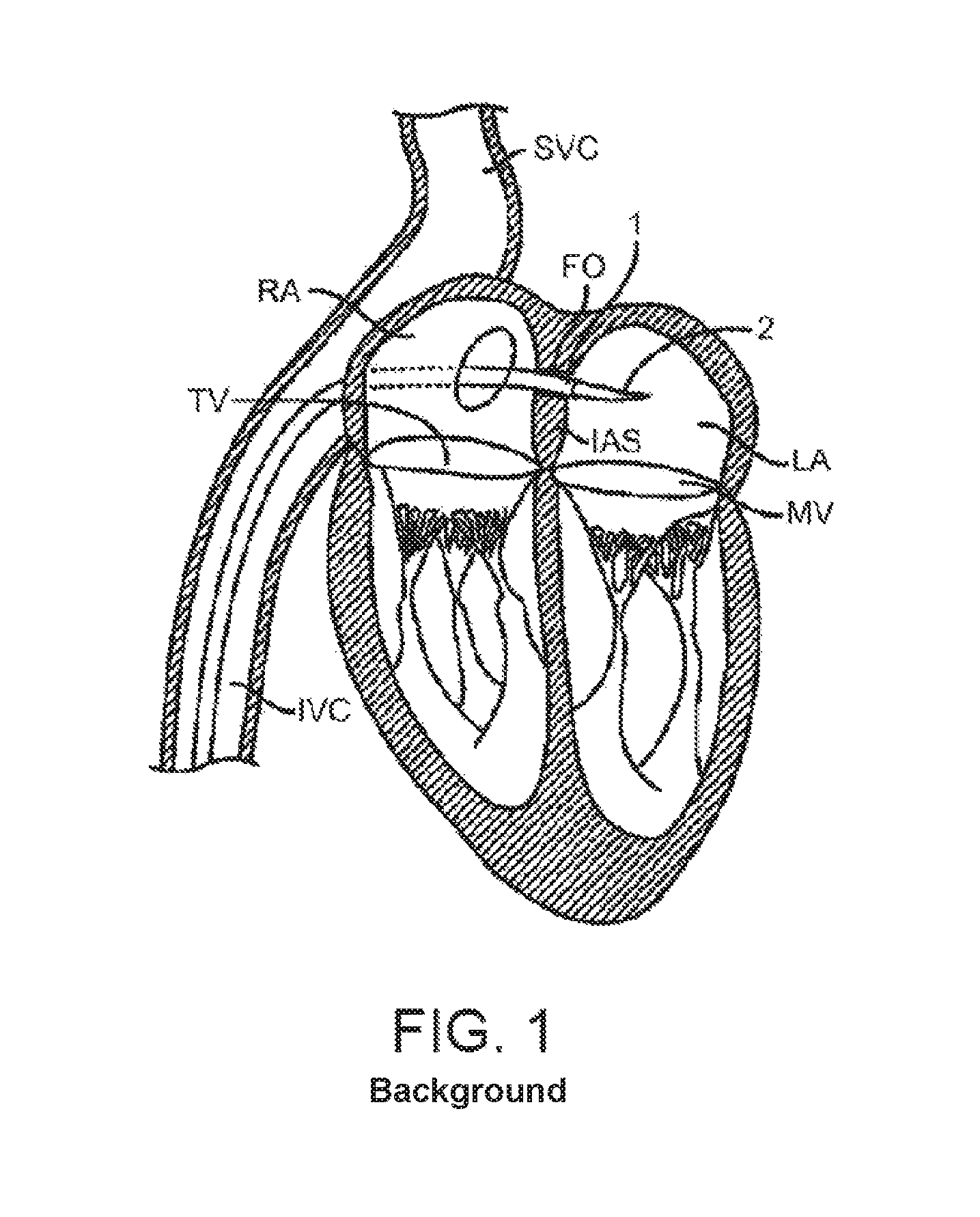
FIG. 1 is a schematic, cross-sectional illustration of the heart showing an antegrade approach to the native mitral valve from the venous vasculature in accordance with various embodiments of the present technology.
FIG. 2 is a schematic, cross-sectional illustration of the heart showing access through the inter-atrial septum (IAS) maintained by the placement of a guide catheter over a guidewire in accordance with various embodiments of the present technology.
FIGS. 3 and 4 are schematic, cross-sectional illustrations of the heart showing retrograde approaches to the native mitral valve through the aortic valve and arterial vasculature in accordance with various embodiments of the present technology.
FIG. 5 is a schematic, cross-sectional illustration of the heart showing an approach to the native mitral valve using a trans-apical puncture in accordance with various embodiments of the present technology.
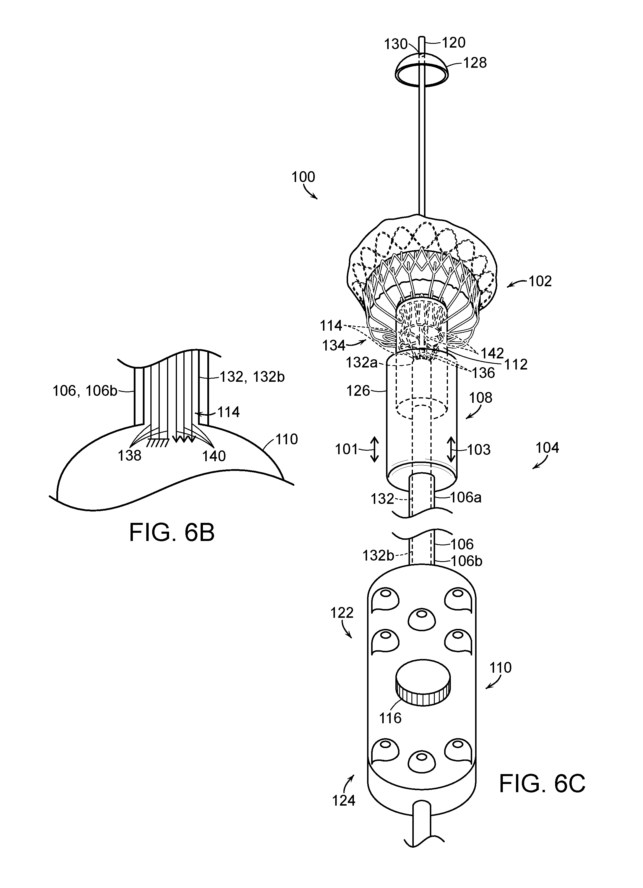
FIG. 6A is a side isometric view of a delivery system with a prosthetic heart valve device in an expanded state in accordance with an embodiment of the present technology.
FIG. 6B is a partially schematic side view of a proximal portion of the delivery system of FIG. 6A.
FIG. 6C is a side isometric view of the delivery system of FIG. 6A with the prosthetic heart valve device in a partially retracted state.
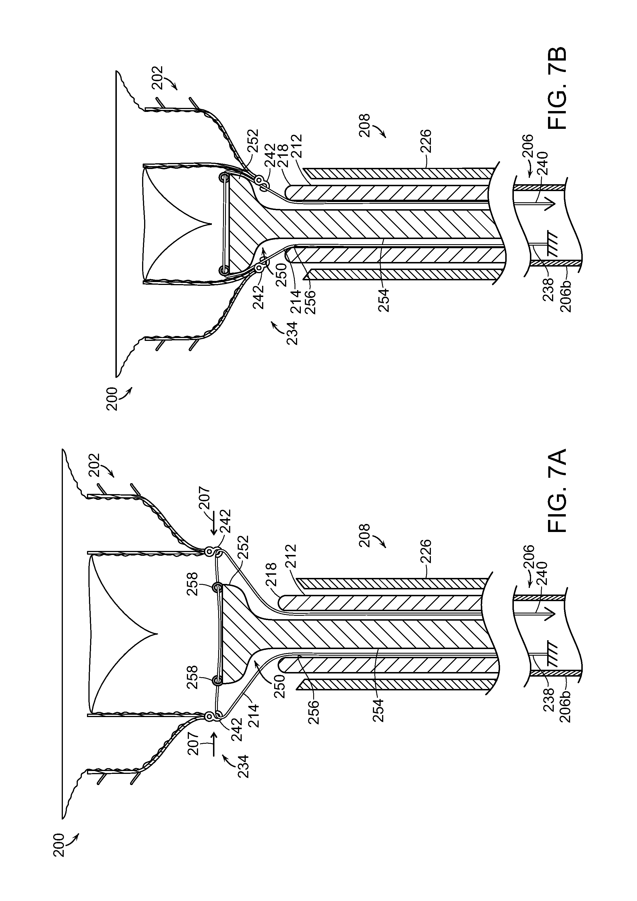
FIG. 7A is a side cross-sectional view of a delivery system with a prosthetic heart valve device in an expanded state in accordance with another embodiment of the present technology.
FIG. 7B is a side isometric view of the delivery system of FIG. 7A with the prosthetic heart valve device in a partially contracted state.
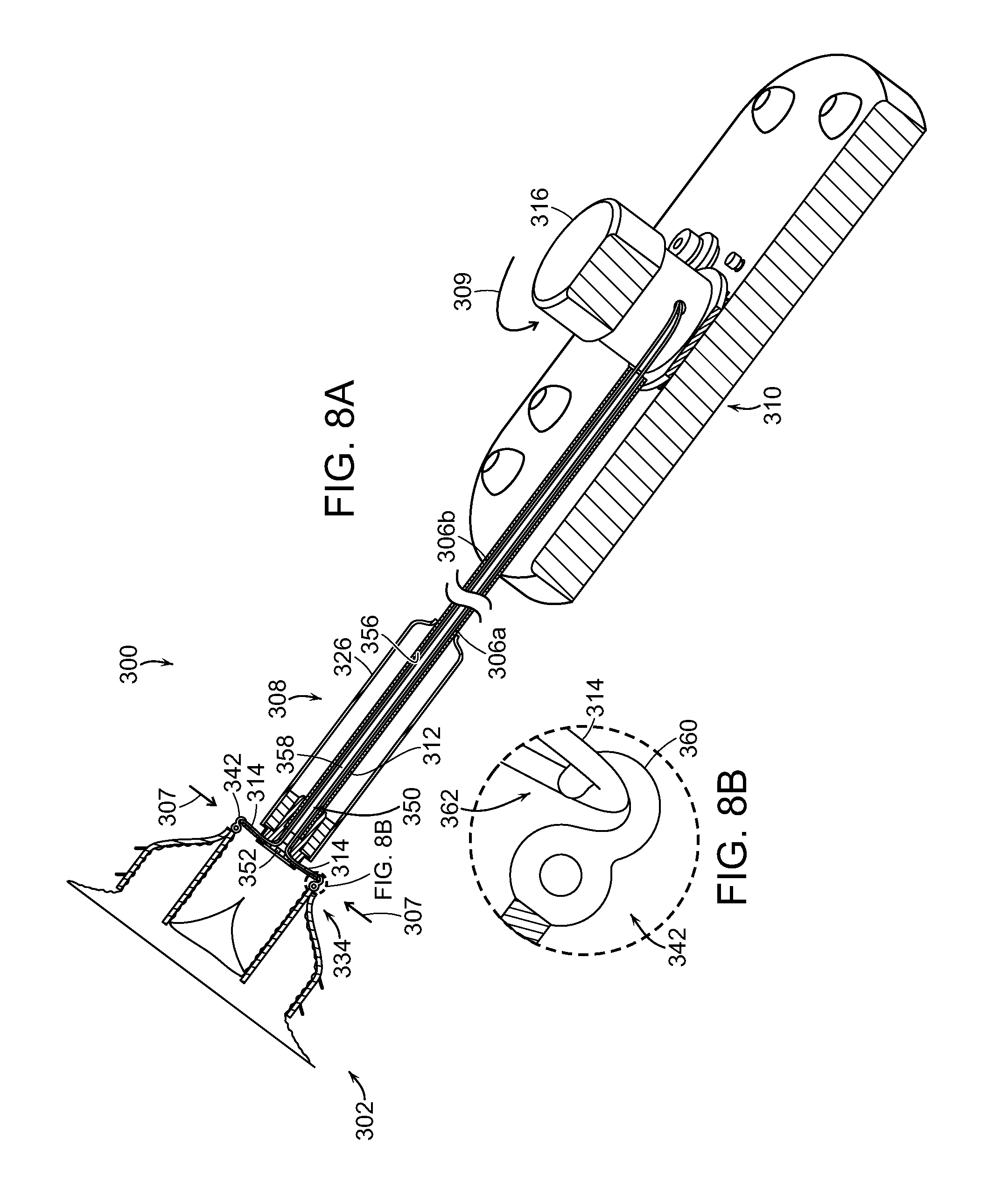
FIG. 8A is a partial cross-sectional isometric view of a delivery system with a prosthetic heart valve device in an expanded state in accordance with yet another embodiment of the present technology.
FIG. 8B is an enlarged side view of a tether element connection site of the delivery system of FIG. 8A.
FIG. 8C is a partially schematic isometric illustration of a tethering arrangement for the delivery system of FIG. 8A.
FIGS. 9A-9C are a series of illustrations showing the resheathing of a prosthetic heart valve device using the delivery system of FIGS. 8A-8C in accordance with embodiments of the present technology
FIG. 10 is a side isometric view of a delivery system for a prosthetic heart valve device configured in accordance with a further embodiment of the present technology.
FIG. 11A is a cross-sectional side view and FIG. 11B is a top view schematically illustrating a prosthetic heart valve device in accordance with an embodiment of the present technology.
FIGS. 12A and 12B are cross-sectional side views schematically illustrating aspects of delivering a prosthetic heart valve device in accordance with an embodiment of the present technology.
FIG. 13 is a top isometric view of a prosthetic heart valve device in accordance with an embodiment of the present technology.
FIG. 14 is a side view and FIG. 15 is a bottom isometric view of the prosthetic heart valve device of FIG. 13.
FIG. 16 is a side view and FIG. 17 is a bottom isometric view of a prosthetic heart valve device in accordance with an embodiment of the present technology.
FIG. 18 is a side view and FIG. 19 is a bottom isometric view of the prosthetic heart valve device of FIGS. 17 and 18 at a partially deployed state with respect to a delivery device.
FIG. 20 is an isometric view of a valve support for use with prosthetic heart valve devices in accordance with the present technology.
FIGS. 21 and 22 are side and bottom isometric views, respectively, of a prosthetic heart valve attached to the valve support of FIG. 20.
FIGS. 23 and 24 are side views schematically showing valve supports in accordance with additional embodiments of the present technology.
DETAILED DESCRIPTION
The present technology is generally directed to delivery systems with tethering features for prosthetic heart valve devices and associated methods. Specific details of several embodiments of the present technology are described herein with reference to FIGS. 1-24. Although many of the embodiments are described with respect to devices, systems, and methods for delivering prosthetic heart valve devices to a native mitral valve, other applications and other embodiments in addition to those described herein are within the scope of the present technology. For example, at least some embodiments of the present technology may be useful for delivering prosthetics to other valves, such as the tricuspid valve or the aortic valve. It should be noted that other embodiments in addition to those disclosed herein are within the scope of the present technology. Further, embodiments of the present technology can have different configurations, components, and/or procedures than those shown or described herein. Moreover, a person of ordinary skill in the art will understand that embodiments of the present technology can have configurations, components, and/or procedures in addition to those shown or described herein and that these and other embodiments can be without several of the configurations, components, and/or procedures shown or described herein without deviating from the present technology.
With regard to the terms "distal" and "proximal" within this description, unless otherwise specified, the terms can reference relative positions of portions of a prosthetic valve device and/or an associated delivery device with reference to an operator and/or a location in the vasculature or heart. For example, in referring to a delivery catheter suitable to deliver and position various prosthetic valve devices described herein, "proximal" can refer to a position closer to the operator of the device or an incision into the vasculature, and "distal" can refer to a position that is more distant from the operator of the device or further from the incision along the vasculature (e.g., the end of the catheter). With respect to a prosthetic heart valve device, the terms "proximal" and "distal" can refer to the location of portions of the device with respect to the direction of blood flow. For example, proximal can refer to an upstream position or a location where blood flows into the device (e.g., inflow region), and distal can refer to a downstream position or a location where blood flows out of the device (e.g., outflow region).
Overview
Several embodiments of the present technology are directed to delivery systems and mitral valve replacement devices that address the unique challenges of percutaneously replacing native mitral valves and are well-suited to be recaptured in a percutaneous delivery device after being partially deployed for repositioning or removing the device. Compared to replacing aortic valves, percutaneous mitral valve replacement faces unique anatomical obstacles that render percutaneous mitral valve replacement significantly more challenging than aortic valve replacement. First, unlike relatively symmetric and uniform aortic valves, the mitral valve annulus has a non-circular D-shape or kidney-like shape, with a non-planar, saddle-like geometry often lacking symmetry. The complex and highly variable anatomy of mitral valves makes it difficult to design a mitral valve prosthesis that conforms well to the native mitral annulus of specific patients. As a result, the prosthesis may not fit well with the native leaflets and/or annulus, which can leave gaps that allows backflow of blood to occur. For example, placement of a cylindrical valve prosthesis in a native mitral valve may leave gaps in commissural regions of the native valve through which perivalvular leaks may occur.
Current prosthetic valves developed for percutaneous aortic valve replacement are unsuitable for use in mitral valves. First, many of these devices require a direct, structural connection between the stent-like structure that contacts the annulus and/or leaflets and the prosthetic valve. In several devices, the stent posts which support the prosthetic valve also contact the annulus or other surrounding tissue. These types of devices directly transfer the forces exerted by the tissue and blood as the heart contracts to the valve support and the prosthetic leaflets, which in turn distorts the valve support from its desired cylindrical shape. This is a concern because most cardiac replacement devices use tri-leaflet valves, which require a substantially symmetric, cylindrical support around the prosthetic valve for proper opening and closing of the three leaflets over years of life. As a result, when these devices are subject to movement and forces from the annulus and other surrounding tissues, the prostheses may be compressed and/or distorted causing the prosthetic leaflets to malfunction. Moreover, a diseased mitral annulus is much larger than any available prosthetic aortic valve. As the size of the valve increases, the forces on the valve leaflets increase dramatically, so simply increasing the size of an aortic prosthesis to the size of a dilated mitral valve annulus would require dramatically thicker, taller leaflets, and might not be feasible.
In addition to its irregular, complex shape, which changes size over the course of each heartbeat, the mitral valve annulus lacks a significant amount of radial support from surrounding tissue. Compared to aortic valves, which are completely surrounded by fibro-elastic tissue that provides sufficient support for anchoring a prosthetic valve, mitral valves are bound by muscular tissue on the outer wall only. The inner wall of the mitral valve anatomy is bound by a thin vessel wall separating the mitral valve annulus from the inferior portion of the aortic outflow tract. As a result, significant radial forces on the mitral annulus, such as those imparted by an expanding stent prostheses, could lead to collapse of the inferior portion of the aortic tract. Moreover, larger prostheses exert more force and expand to larger dimensions, which exacerbates this problem for mitral valve replacement applications.
The chordae tendineae of the left ventricle may also present an obstacle in deploying a mitral valve prosthesis. Unlike aortic valves, mitral valves have a maze of cordage under the leaflets in the left ventricle that restrict the movement and position of a deployment catheter and the replacement device during implantation. As a result, deploying, positioning and anchoring a valve replacement device on the ventricular side of the native mitral valve annulus is complicated.
Embodiments of the present technology provide systems, methods and apparatus to treat heart valves of the body, such as the mitral valve, that address the challenges associated with the anatomy of the mitral valve and provide for repositioning and removal of a partially deployed device. The apparatus and methods enable a percutaneous approach using a catheter delivered intravascularly through a vein or artery into the heart, or through a cannula inserted through the heart wall. For example, the apparatus and methods are particularly well-suited for trans-septal and trans-apical approaches, but can also be trans-atrial and direct aortic delivery of a prosthetic replacement valve to a target location in the heart. Additionally, the embodiments of the devices and methods as described herein can be combined with many known surgeries and procedures, such as known methods of accessing the valves of the heart (e.g., the mitral valve or triscuspid valve) with antegrade or retrograde approaches, and combinations thereof.
The systems and methods described herein facilitate resheathing of a prosthetic heart valve device after partial or full deployment of the heart valve device. The disclosed delivery systems include tether elements that are releasably attached to the heart valve device and retracted to facilitate resheathing of the device. For example, the retraction of the tether elements can at least partially collapse a ventricular portion of the heart valve device, and an open end of a delivery capsule can receive the cinched end to initiate resheathing. In certain embodiments, the partially collapsed portion of the heart valve device can be received in a cinching member that projects from the delivery capsule and further facilitates contraction of the ventricular portion of the heart valve device. This partial or full resheathing of the heart valve device allows clinicians to reposition the device, in vivo, or remove the device after partial or full deployment of the device.
Access to the Mitral Valve
To better understand the structure and operation of valve replacement devices in accordance with the present technology, it is helpful to first understand approaches for implanting the devices. The mitral valve or other type of atrioventricular valve can be accessed through the patient's vasculature in a percutaneous manner. By percutaneous it is meant that a location of the vasculature remote from the heart is accessed through the skin, typically using a surgical cut down procedure or a minimally invasive procedure, such as using needle access through, for example, the Seldinger technique. The ability to percutaneously access the remote vasculature is well known and described in the patent and medical literature. Depending on the point of vascular access, access to the mitral valve may be antegrade and may rely on entry into the left atrium by crossing the inter-atrial septum (e.g., a trans-septal approach). Alternatively, access to the mitral valve can be retrograde where the left ventricle is entered through the aortic valve. Access to the mitral valve may also be achieved using a cannula via a trans-apical approach. Depending on the approach, the interventional tools and supporting catheter(s) may be advanced to the heart intravascularly and positioned adjacent the target cardiac valve in a variety of manners, as described herein.
FIG. 1 illustrates a stage of a trans-septal approach for implanting a valve replacement device. In a trans-septal approach, access is via the inferior vena cava IVC or superior vena cava SVC, through the right atrium RA, across the inter-atrial septum IAS, and into the left atrium LA above the mitral valve MV. As shown in FIG. 1, a catheter 1 having a needle 2 moves from the inferior vena cava IVC into the right atrium RA. Once the catheter 1 reaches the anterior side of the inter-atrial septum IAS, the needle 2 advances so that it penetrates through the septum, for example at the fossa ovalis FO or the foramen ovale into the left atrium LA. At this point, a guidewire replaces the needle 2 and the catheter 1 is withdrawn.
FIG. 2 illustrates a subsequent stage of a trans-septal approach in which guidewire 6 and guide catheter 4 pass through the inter-atrial septum IAS. The guide catheter 4 provides access to the mitral valve for implanting a valve replacement device in accordance with the technology.
In an alternative antegrade approach (not shown), surgical access may be obtained through an intercostal incision, preferably without removing ribs, and a small puncture or incision may be made in the left atrial wall. A guide catheter passes through this puncture or incision directly into the left atrium, sealed by a purse string-suture.
The antegrade or trans-septal approach to the mitral valve, as described above, can be advantageous in many respects. For example, antegrade approaches will usually enable more precise and effective centering and stabilization of the guide catheter and/or prosthetic valve device. The antegrade approach may also reduce the risk of damaging the chordae tendinae or other subvalvular structures with a catheter or other interventional tool. Additionally, the antegrade approach may decrease risks associated with crossing the aortic valve as in retrograde approaches. This can be particularly relevant to patients with prosthetic aortic valves, which cannot be crossed at all or without substantial risk of damage.
FIGS. 3 and 4 show examples of a retrograde approaches to access the mitral valve. Access to the mitral valve MV may be achieved from the aortic arch AA, across the aortic valve AV, and into the left ventricle LV below the mitral valve MV. The aortic arch AA may be accessed through a conventional femoral artery access route or through more direct approaches via the brachial artery, axillary artery, radial artery, or carotid artery. Such access may be achieved with the use of a guidewire 6. Once in place, a guide catheter 4 may be tracked over the guidewire 6. Alternatively, a surgical approach may be taken through an incision in the chest, preferably intercostally without removing ribs, and placing a guide catheter through a puncture in the aorta itself. The guide catheter 4 affords subsequent access to permit placement of the prosthetic valve device, as described in more detail herein. Retrograde approaches advantageously do not need a trans-septal puncture. Cardiologists also more commonly use retrograde approaches, and thus retrograde approaches are more familiar.
FIG. 5 shows a trans-apical approach via a trans-apical puncture. In this approach, access to the heart is via a thoracic incision, which can be a conventional open thoracotomy or sternotomy, or a smaller intercostal or sub-xyphoid incision or puncture. An access cannula is then placed through a puncture in the wall of the left ventricle at or near the apex of the heart. The catheters and prosthetic devices of the invention may then be introduced into the left ventricle through this access cannula. The trans-apical approach provides a shorter, straighter, and more direct path to the mitral or aortic valve. Further, because it does not involve intravascular access, the trans-apical approach does not require training in interventional cardiology to perform the catheterizations required in other percutaneous approaches.
Selected Embodiments of Delivery Systems for Prosthetic Heart Valve Devices
FIG. 6A is a side isometric view of a delivery system 100 with a prosthetic heart valve device 102 ("device 102") in an expanded state in accordance with an embodiment of the present technology; FIG. 6B is a partially schematic side view of a proximal portion of the delivery system 100; and FIG. 6C is a side isometric view of the delivery system 100 with the device 102 in a partially retracted state. The delivery system 100 includes a catheter 104 having an elongated catheter body 106 ("catheter body 106") with a distal portion 106a carrying a delivery capsule 108 ("capsule 108") and a proximal portion 106b coupled to a control unit or handle assembly 110. The capsule 108 can move between a containment configuration for holding the device 102 in an unexpanded state during delivery of the device 102 and a deployment configuration in which the device 102 is at least partially expanded from the capsule 108. The delivery system 100 further includes a cinching member 112 slidably disposed within at least a distal portion of the capsule 108 and a plurality of tether elements 114 that are releasably coupled to the device 102. The tether elements 114 can be wires, sutures, or cables that extend through the cinching member 112 and through the catheter body 106 to the proximal portion 106b of the catheter body 106. At the proximal portion 106b, the tether elements 114 operably couple to an actuator 116 of the handle assembly 110 that can be manipulated to retract the tether elements 114 proximally or release the tether elements 114 distally.
In certain embodiments, the catheter 104 can be configured to travel over a guidewire 120, which can be used to guide the capsule 108 into a native heart valve. After the device 102 has been deployed (e.g., as shown in FIG. 6A), proximal retraction of the tether elements 114 (e.g., via the actuator 116 of the handle assembly 110) reduces the diameter of a proximal or ventricular end portion 134 of the device 102 and urges the device 102 and a distal end portion 118 of the cinching member 112 closer together axially to facilitate resheathing at least a portion of the device 102. The partial or full resheathing of the device 102 allows for repositioning of the device 102 relative to the native heart valve (e.g., a native mitral valve) after a portion of the device 102 has contacted tissue of the native valve. As shown in FIG. 6C, in certain embodiments proximal retraction of the tether elements 114 pulls the ventricular end portion 134 of the device 102 into the distal end portion 118 of the cinching member 112 such that the end of the device 102 is covered as the capsule is advanced distally for resheathing.
The handle assembly 110 can provide steering capability (e.g., 360 degree rotation of the delivery capsule 108, 180 degree rotation of the delivery capsule 108, 3-axis steering, 2-axis steering, etc.) for delivering the capsule 108 to a target site (e.g., to a native mitral valve). The handle assembly 110 can also have additional features to initiate deployment of the device 102 at the target site. For example, the handle assembly 110 can include a control assembly 122 and a steering mechanism 124. The control assembly 122 can include rotational elements, such as a knob, that can be rotated to rotate the capsule 108 about its longitudinal axis. The control assembly 122 can also include buttons, levers, and/or other actuators that allow a clinician to control the deployment and/or resheathing mechanisms of the delivery system 100. For example, the illustrated control assembly 122 includes the actuator 116, which can be rotated in a first direction to pull the tether elements 114 proximally to at least partially resheathe the device 102 and rotated in an opposite direction to relax the tether elements 114 to allow for redeployment of the device 102. In other embodiments, the actuator 116 can be manipulated in a different manner (e.g., pulling) to pull and relax the tether elements 114. The actuator 116 can be operably coupled to twisting or pulling mechanisms that interact with the tether elements 114 to provide for the controlled movement of the tether elements 114. The steering mechanism 124 can be used to steer the catheter 104 through the anatomy by bending the distal portion 106a of the catheter body 106 about a transverse axis. In other embodiments, the handle assembly 110 may include additional and/or different features that facilitate delivering the device 102 to the target site.
The capsule 108 at the distal end portion 106a of the catheter body 106 includes a housing 126 configured to carry the device 102 and, optionally, an end cap 128 extending distally from the housing 126. As shown in FIG. 6A, the end cap 128 can include an opening 130 at its distal end through which the guidewire 120 can be threaded to allow for guidewire delivery to the target site. The end cap 128 can also have an atraumatic shape (e.g., a partially spherical shape, a frusto-conical shape, blunt configuration, rounded configuration, etc.) to facilitate atraumatic delivery of the capsule 108 to the target site. In certain embodiments, only the housing 126 carries the device 102 (e.g., the device is contained completely within just the housing 126), while in other embodiments the end cap 128 can have proximal sidewalls such that a portion of the device 102 is contained within the end cap 128. The housing 126 and/or the end cap 128 can be made of metal, polymers, plastic, composites, combinations thereof, or other materials capable of holding the device 102. As discussed in further detail below, manipulating the handle assembly 110 pulls the capsule 108 in a proximal direction to move the capsule 108 from the containment configuration to the deployment configuration and expand the device 102 from the capsule 108. In certain embodiments, manipulating the handle assembly 110 drives the end cap 128 in a distal direction to open the capsule 108. In other embodiments, the end cap 128 can be omitted and the capsule 108 can include a proximal housing and a distal housing, which both enclose portions of the device 102 in the containment configuration. During deployment, the proximal and distal housings can move proximally and distally in a simultaneous or sequential manner to deploy the device 102 from the capsule 108.
As shown in FIG. 6A, the delivery system 100 can further include a push rod 132 that extends through the catheter body 106 and is used to deploy the device 102 from the capsule 108. The push rod 132 has a distal end portion 132a (e.g., a platform) positioned proximate to a ventricular end portion 134 of the device 102 and a proximal end portion 132b coupled to the handle assembly 110. The push rod 132 can be made of metal, polymers, plastic, composites, combinations thereof, or other materials with the flexibility necessary to navigate through the anatomy to the target site and sufficient rigidity to support the device 102 during delivery. In certain embodiments, the distal end portion 132a may have a different flexibility than the proximal end portion 132b.
As indicated by the arrows 101 and 103 of FIGS. 6A and 6C, the push rod 132 and the capsule 108 can move relative to each other to initiate deployment of the device 102 from the capsule 108. For example, the proximal end portion 132b of the push rod 132 can be fixed relative to the handle assembly 110 such that distal movement of the handle assembly 110 drives the push rod 132 distally, causing the distal end portion 132a of the push rod 132 to press against the ventricular end portion 134 of the device 102 and eject at least a portion of the device 102 from the capsule 108. In other embodiments, the proximal portion 132b of the push rod 132 slides with respect to the handle assembly 110 such that the handle assembly 110 can pull the capsule 108 proximally, while the distal end portion 132a of the push rod 132 holds the device 102 in a substantially constant position relative to the longitudinal axis of the catheter body 106 for unsheathing the device 102. In further embodiments, the delivery system 100 can include other mechanisms for deploying the device 102 from the capsule 108.
In the embodiment illustrated in FIGS. 6A and 6C, the cinching member 112 is a tubular structure fixedly coupled to the distal end portion 132a of the push rod 132 and axially movable with respect to the capsule 108. Thus, movement of the push rod 132 (e.g., via the handle assembly 110 fixedly attached thereto) also moves the cinching member 112. The cinching member 112 and the distal end portion 132a of the push rod 132 can be housed in the capsule 108 or the distal portion 106a of the catheter body 106. Accordingly, the cinching member 112 has a diameter or outer dimension that is less than the diameter or inner dimension of the capsule 108 or, if housed in the catheter body 106, less than the diameter or inner dimension of the distal portion 106a of the catheter body 106. The cinching member 112 can be made from similar materials as the push rod 132, such as metals, polymers, and/or other materials with sufficient rigidity to allow a portion of the device 102 to contract into the distal end portion 118 of the cinching member 112. The cinching member 112 can be attached to the push rod 132 via welding, gluing, and/or other attachment methods. In other embodiments, the cinching member 112 can be integrally formed as an extension of the push rod 132. In further embodiments, the cinching member 112 and the push rod 132 can be separate elements extending alongside each other along the length of the catheter body 106. In this embodiment, the cinching member 112 and the push rod 132 can be fixedly attached to each other such that proximal and distal movement of the cinching member 112 or the push rod 132 imparts movement on the other of the cinching member or the push rod 132. Alternatively, the push rod 132 and the cinching member 112 may be configured to move independently of each other, and in such an embodiment the push rod 132 and the cinching member 112 can be arrange coaxially with each other or side-by-side along the length of the catheter body 106.
The cinching member 112 can be used to facilitate resheathing of the device 102 after partial or full deployment of the device 102. For example, after the device 102 has been deployed from the capsule 108, the clinician can move the push rod 132 in a distal direction until the distal end portion 118 of the cinching member 112 is exposed from the distal end of the capsule 108 (e.g., as shown in FIG. 6A). As explained in further detail below, this distal movement of the cinching member 112 constrains distal portions of the tether elements 114 within the inner diameter of the cinching member 112, which can cause the ventricular end portion 134 of the device 102 to partially collapse or be constrained in the distal end portion 118 of the cinching member 112.
The tether elements 114 are releasably coupled to the ventricular end portion 134 of the device 102 via a plurality of attachment features 142. As shown in FIGS. 6A and 6C, the attachment features 142 can be loops or eyelets spaced around the perimeter of the device 102. In the illustrated embodiment, the device 102 includes six attachment features 142 and three tether elements 114 attached thereto. Each tether element 114 is threaded through a first loop and through a second loop spaced circumferentially apart from the first loop on the ventricular end portion 134 of the device 102 such that each tether element 114 extends across a portion (e.g., a diameter or a chord) of the device 102. In other embodiments, each tether element 114 can attached to only one attachment feature 142 or connect to more than two attachment features 142. In further embodiments, the attachment features 142 can have different configurations, such as hooks or clasps that releasably attach the tether elements 114 to the device 102. In still further embodiments, the delivery system 100 includes different quantities of attachment features 142 and/or tether elements 114.
The tether elements 114 extend through the catheter body 106 to the proximal portion 106b of the catheter body 106 where they are operably coupled to the actuator 116 of the handle assembly 110. In the illustrated embodiment, the tether elements 114 extend through the cinching member 112 and into the push rod 132 to the proximal end portion 106b of the catheter body 106. As shown in FIG. 6A, the distal end portion 132a of the push rod 132 can include guide structures 136, such as eyelets, channels, or loops, that route the tether elements 114 into an opening of the push rod 132 and space the tether elements 114 apart from each other about the perimeter of the distal end of the push rod 132. In other embodiments, the push rod 132 and/or the cinching member 112 can include additional guide structures 136 that route the tether elements 114 along the length of push rod 132 and/or the cinching member 112. In further embodiments, the tether elements 114 may extend alongside the exterior of the push rod 132 rather than through the push rod 132. In this embodiment, the cinching member 112 may have openings through which the tether elements extend outside of the push rod 132 or the cinching member 112 may be a separate tubular structure around the push rod 132 that contains the tether elements 114.
Referring to FIG. 6B, each tether element 114 has a first end 138 fixed at the handle assembly 110 and a movable second end 140 that can be pulled proximally and relaxed to collapse or re-expand the device 102. The individual tether elements 114 extend from the fixed first ends 138, through the catheter body 106, to the device 102 where they are releasably coupled thereto, and extend back through the catheter body 106 to the movable second ends 140. The second ends 140 of the tether elements 114 can be operably coupled to the actuator 116 (FIG. 6A) and the actuator can be manipulated in one manner (e.g., pulled or rotated in a first direction) to tighten and proximally retract the tether elements 114 and can be manipulated in another manner (e.g., pushed or rotated in a second direction) to relax and distally advance the tether elements 114. In other embodiments, the second end 140 of each tether element 114 can be individually manipulated by individual actuators to selectively pull and release the individual tether elements 114.
During deployment of the device 102 at native mitral valve, the end cap 128 can be moved distally and the capsule 108 can be moved to the deployment configuration (FIG. 6A) using the push rod 132 and/or other suitable mechanical or hydraulic deployment mechanisms to unsheathe the device 102 from housing 126 of the capsule 108. As the device 102 exits the housing 126, the device 102 expands and presses against tissue on an inner surface of the annulus of the mitral valve to secure the device 102 in the mitral valve. If the clinician elects to reposition or remove the device 102, the cinching member 112 and the tether elements 114 can be used to partially or fully resheathe the device 102 after full deployment from the capsule 108. More specifically, a clinician can move the cinching member 112 distally (as indicated by arrow 105) by manipulating the push rod 132 via the handle assembly 110 such that the cinching member 112 projects from the distal end of the capsule 108 (e.g., as shown in FIG. 6A). This distal movement of the cinching member 112 constrains the tether elements 114 together within the cinching member 112, which can in turn cinch up the ventricular end portion 134 of the device 102. The clinician can also move (e.g., rotate) the actuator 116 at the handle assembly 110 to pull the tether elements 114 in a proximal direction. This too can cinch the ventricular end portion 134 of the device 102 and allows the clinician to move the delivery catheter 104 distally toward the device 102.
As shown in FIG. 6C, the interplay between the cinching member 112 and the proximal retraction of the tether elements 114 can at least partially collapse the ventricular end portion 134 of the device 102 to a diameter or outer dimension that allows the device 102 to be at least partially received within the distal end portion 118 of the cinching member 112. This pre-collapses the ventricular end portion 134 of the device 102 before resheathing the device 102 within the capsule 108. The clinician can then move the cinching member 112 with the device 102 partially contained therein in a proximal direction toward the capsule 108 so that the device 102 can be partially or fully resheathed within the capsule 108. Alternatively, the capsule 108 can be moved in a distal direction over the cinched end of the device 102 to at least partially resheathe the device 102 within the capsule 108. In other embodiments, the capsule 108 can be moved distally while the cinching member 112 with the device 102 is drawn proximally to initiate resheathing. The partial contraction of the device 102 provided by the tether elements 114 and the cinching member 112 allows the open end of the capsule 108 to easily receive the cinched end because the cinched ventricular end portion 134 has a diameter smaller than that of the delivery capsule 108. For further resheathing, the partial contraction of the device 102 provided by the tether elements 114 and the cinching member 112 allows the capsule 108 to glide along the peripheral walls of the device 102 to further contract the device 102 and move it back into the sheathed, containment configuration in the capsule 108. As described in further detail below with reference to FIGS. 11-24, the device 102 itself can include smooth and continuous outer walls that further facilitate this resheathing. This partial or full resheathing of the device 102 allows clinicians to reposition the device 102, in vivo, or remove the device 102 after full deployment and after the device 102 has contacted tissue of the native valve.
Once the device 102 has been fully deployed within the native valve at its final position, the tether elements 114 can be disengaged from the device 102 to release the device 102 from the delivery system 100. For example, the first ends 138 (FIG. 6B) of the tether elements 114 can be released from their fixed positioned by cutting or otherwise freeing the fixed first ends 138, and the second ends 240 (FIG. 6B) of the tether elements 114 can be pulled in a proximal direction (e.g., by rotating about a spindle on the actuator 116). As the second ends 140 are retracted, the first ends 138 move through the catheter body 106, thread through the attachment features 142 of the device 102, and back into the catheter body 106 such that the tether elements 114 are no longer connected to the device 102. In other embodiments, the tether elements 114 can disengage from the device 102 using other suitable mechanism, such as cutting the tethers at a region closer to the capsule 108. After the tether elements 114 are released from the device 102, the delivery system 100 to be removed from the patient while the device 102 remains implanted at the native valve.
FIG. 7A is a side cross-sectional view of a delivery system 200 with a prosthetic heart valve device 202 ("device 202") in an expanded state in accordance with another embodiment of the present technology, and FIG. 7B is a side isometric view of the delivery system 200 of FIG. 7A with the device 202 in a partially contracted state. The delivery system 200 includes various features at least generally similar to the features of the system 100 described above with reference to FIGS. 6A-6C. For example, the delivery system 200 includes a delivery capsule 208 having a housing 226 that holds the device 202 in a containment configuration, a cinching member 212 extending at least partially through the capsule 208, and at least one tether element 214 that can be used to at least partially resheathe the device 202 after full deployment at a target site (e.g., a native mitral valve). The cross-sectional view of FIGS. 7A and 7B shows only one tether element 214, but the delivery system 200 can include additional tether elements 214 arranged around the device 202 in a similar manner as the illustrated tether element 214. For example, the delivery system 200 may include two, three, four, five, six, or more tether elements 214 spaced apart around the circumference of the device 202. In the embodiment illustrated in FIGS. 7A and 7B, the cinching member 212 has a tubular structure that extends through a catheter body 206 to a proximal portion 206b of the catheter body 206 (distal portion of the catheter body 206 not shown for illustrative purposes) and contains the tether element(s) 214. At the proximal portion 206b of the catheter body 206, a first end 238 of each tether element 214 can be fixed and a second end 240 can be movable to allow a clinician to retract the tether element(s) 214 proximally and release the tether element(s) 214 distally to facilitate resheathing of the device 202. For example, the second end 240 of the tether element 214 can be attached to an actuator (not shown; e.g., the actuator 116 of FIGS. 6A and 6C) at a handle assembly (not shown; e.g., the handle assembly 110 of FIGS. 6A and 6C), which can be used to move the tether element 214.
In the embodiment illustrated in FIGS. 7A and 7B, the delivery system 200 includes a platform 250 that is operably coupled to the capsule 208 to initiate deployment of the device 202 from the capsule 208. The platform 250 can include a distal end portion 252, such as a flange or a pedestal, configured to support a ventricular end portion 234 of the device 202 during deployment and a shaft portion 254 extending proximally from the distal end portion 252 and at least partially through the capsule 208. In various embodiments, the platform 250 maintains the position of the device 202 at a desired target site relative to the longitudinal axis of the catheter body 206 as the capsule 208 is pulled in a proximal direction to unsheathe the device 202. As shown in FIGS. 7A and 7B, the shaft portion 254 of the platform 250 extends through the tubular cinching member 212 to create a tether channel 256 defined by an inner surface of the cinching member 212 and an outer surface of the platform 250 and configured to receive the tether element(s) 214. Each tether element 214 extends from the first end 238, through the tether channel 256, through one or more attachment features 242 on the ventricular end portion 234 of the device 202, and back through the tether channel 256 to the proximal portion 206b of the catheter body 206 where the second end 240 can be operably coupled to an actuator for controlling the tether element 214. As shown in FIGS. 7A and 7B, the distal end portion 252 of the platform 250 can also include one or more attachment elements 258 that releasably connect the tether element(s) 214 to the platform 250. In the illustrated embodiment, the attachment elements 258 are eyelets or loops through which the tether element(s) 214 can be threaded. In other embodiments, the attachment elements are hooks or other features for releasably engaging the tether elements 214.
In certain embodiments, the cinching member 212 and the platform 250 are fixed relative to each other such that movement of the platform 250 translates to movement of the cinching member 212 and vice versa. During deployment, the device 202 expands from the capsule 208 as the housing 226 of the capsule 208 moves proximally and/or the platform 250 pushes the device 202 distally. After the device 202 has been fully expanded, a distal end portion 218 of the cinching member 212 can be moved such that it projects distally from the capsule 208 and, due to the fixed relationship between the platform 250 and the cinching member 212, the distal end portion 252 of the platform 250 projects distally from the cinching member 212. In this fully expanded state shown in FIG. 7A, the clinician can pull the tether elements 214 in a proximal direction to at least partially resheathe the device 202 to reposition or otherwise manipulate the device 202. The proximal retraction of the tether elements 214 partially collapses the ventricular end portion 234 of the device 202 such that it moves inward in the direction of arrows 207 (FIG. 7A) toward the distal end portion 252 of the platform 250 and hugs the platform 250. As shown in FIG. 7B, proximal retraction of the tether elements 214 may also move the device 202 in a proximal direction toward the cinching member 212 and cause the ventricular end portion 234 to wrap around the distal end portion 252 of the platform 250. In certain embodiments, the partially collapsed ventricular end portion 234 of the device 202 may cinch against the area between the platform 250 and the distal end portion 218 of the cinching member 212 or the ventricular end portion 234 may be at least partially received within the distal end portion 218 of the cinching member 212. In this embodiment, the ventricular end portion 234 of the device 202 contracts to the inner diameter of the cinching member 212, which is less than the diameter of the capsule 208.
When the device 202 is in the partially collapsed state (FIG. 7B), the clinician can move the cinching member 212 and/or the platform 250 in a proximal direction to partially or fully resheathe the device 202 in the capsule 208, and/or the clinician can move the capsule 208 in a distal direction over the cinched end of the device 202. The partially collapsed device 202 allows the open end of the capsule 208 to easily slide over the cinched end because the cinched ventricular end portion 234 has a diameter smaller than that of the delivery capsule 208. In addition, the arrangement shown in FIG. 7B in which the ventricular end portion 234 of the device 202 hugs or wraps around the distal end portion 252 of the platform 250 allows the platform 250 to provide support to the collapsed portion of the device 202 during resheathing and is expected to enhance stability at the ventricular end portion 234 during resheathing. After the cinched ventricular end portion 234 has been received in the capsule 208, resheathing can continue by sliding the capsule 208 along the peripheral walls of the device 202 to further collapse the device 102 and move the device 102 back into its unexpanded state to the containment configuration in the capsule 208. The partially or fully sheathed device 202 can then be repositioned and redeployed at a desired location. After final deployment at the target site, the clinician can disengage the tether elements 214 from the device 202 by severing the fixed first ends 238 to release the device 202 from the delivery system 200 and remove the delivery system 200 from the patient.
FIG. 8A is a is a partial cross-sectional isometric view of a delivery system 300 with a prosthetic heart valve device 302 ("device 302") in an expanded state in accordance with yet another embodiment of the present technology, and FIG. 8B is an enlarged side view of a tether element connection site for the delivery system 300. The delivery system 300 includes various features at least generally similar to the features of the delivery system 200 described above with reference to FIGS. 7A and 7B. For example, the delivery system 300 includes an elongated catheter body 306 ("catheter body 306"), a delivery capsule 308 carried by a distal portion 306a of the catheter body 306, a cinching member 312 extending at least partially through the capsule 308, and a platform 350 with a distal end portion 352 and a shaft portion 354 that extends through the cinching member 312. In the illustrated embodiment, the cinching member 312 attaches to a distal region of the shaft portion 354 of the platform 350 and, therefore, the platform 350 and the cinching member 312 are fixed relative to each other. The platform 350 can be configured to move the capsule 308 between the containment configuration and the deployment configuration (FIG. 8A) to unsheathe and resheathe the device 302.
As shown in FIG. 8A, the delivery system 300 further includes tether elements 314 that extend along the length of the catheter body 306 and through a tether channel 358 defined by the platform 350. Accordingly, the shaft portion 354 of the platform 350 may be a tubular structure. In other embodiments, the cinching member 312 extends alongside a greater length of the shaft portion 354 and/or has a tubular structure that defines a channel for receiving the tether elements 314. The tether elements 314 are releasably coupled to attachment features 342 at a ventricular end portion 334 of the device 302. An actuator 316 can be rotated (as indicated by arrow 309) to proximally retract the tether elements 314, which in turn pulls the ventricular end portion 334 of the device 302 inward toward a distal end portion 352 of the platform 350 (as indicated by arrows 307) to partially collapse the device 302. In other embodiments, the actuator 316 can be manipulated using other suitable means for retracting and releasing the tether elements 314. Similar to the delivery system 200 of FIGS. 7A and 7B, the partially collapsed device 302 can hug and/or wrap around the distal end portion 352 of the platform 350 to facilitate resheathing the device 302 after full deployment.
As shown best in FIG. 8B, the attachment features 342 of the delivery system 300 are hooks 360 positioned at the ventricular end portion 334 of the device 302, and the tether elements 314 form loops 362 that extend around the hooks 360. The hooks 360 may each have a one-way notch that allows the hook 360 to flex open to receive the tether element 314, and flex closed after insertion to prevent disengagement of the tether element 314 from the hook 360. In other embodiments, the delivery system 300 can include both hooks 360 and the eyelet attachment structures of FIG. 6A-7B or the hooks 360 can be replaced by the eyelet attachment structures such that the tether elements 314 are threaded through the eyelets.
Unlike the tether elements of FIGS. 6A-7B that extend across the prosthetic device between two or more attachment features, the individual tether elements 314 of the delivery system 300 extend from of the distal end portion 318 of the cinching member 312, wrap around a single hook 360, and extend back through the distal end portion 318 of the cinching member 312 into the tether channel 356 to form individual loops 362. FIG. 8C, for example, is a partially schematic isometric illustration of the tethering arrangement for the delivery system 300. As shown in FIG. 8C, the loops 362 of the tether elements 314 extend from the housing 326 of the capsule 308 and splay outward into a petal-like configuration with loops 362 arranged in a manner to engage corresponding attachment features 342 (e.g., hooks 360 of FIGS. 8A and 8B) positioned circumferentially around the device 302. Each loop 362 is defined by a single tether element 314 that extends from a fixed first end 338 at the proximal portion 306b of the catheter body 306, through the catheter body 306 into engagement with an attachment feature 342 (FIG. 8A), and back through the catheter body 306 where a second end 340 of the tether element 314 attaches to the actuator 316 (FIG. 8A) that can be manipulated to proximally retract the tether element 314. In the illustrated embodiment, the delivery system 300 includes nine loops 362, but in other embodiments the delivery system 300 can include fewer than nine loops 362 or more than nine loops 362 that attach to one or more corresponding attachment features 342 on the ventricular end portion 334 of the device 302 (FIG. 8A). The looped tether elements 314 can be attached to the hooks 360 when the device 302 is loaded in the capsule 308 and continuously engage the hooks 360 until the clinician is ready to fully release the device 302 from the delivery system 300. After deployment and optional resheathing, the tether elements 314 can be disconnected from the hooks 360 by releasing the fixed ends of the tether elements 314 and pulling the tether elements 314 proximally until the tether elements 314 no longer loop around the hooks 360.
FIGS. 9A-9C are a series of illustrations showing the resheathing of the device 302 using the delivery system 300 of FIGS. 8A-8C in accordance with embodiments of the present technology. In FIG. 9A, the device 302 has been fully deployed from the housing 326 of the capsule 308, and the tether elements 314 maintain engagement with the device 302 while the device 302 is in the fully expanded state. The distal portion 318 of the cinching member 312 extends distally from the open capsule 308, and the distal end portion 352 of the platform 350 projects distally therefrom. As shown in FIG. 9A, the distal end portion 352 of the platform 350 includes a plurality of openings 364 through which the loop 362 of each tether element 314 extends so that the individual loops 362 can attach to corresponding hooks 360 on the ventricular end portion 334 of the device 302. In other embodiments, the distal end portion 352 of the platform 350 has a single opening at the distal-most end through which all of the tether elements 314 exit the tether channel 358 of the platform 350.
Referring to FIG. 9B, if the clinician elects to resheathe the device 302, the tether elements 314 can be retracted proximally using the actuator 316. This proximal retraction pulls the tether elements 314 inward toward the platform 350 in the direction of arrows 307, and this in turn cinches the ventricular end portion 334 of the device 302 such that it hugs the distal end portion 352 of the platform 350. As shown in FIG. 9C, the capsule 308 can then be moved in a distal direction (as indicated by arrow 311) to slide over the partially collapsed device 302 and at least partially resheathe the device 302 to allow for in vivo repositioning or removal of the device. The cinched ventricular end portion 334 and the support provided by the platform 350 are expected to facilitate resheathing of the device 302 after full deployment. After final deployment at the target site, the clinician can fully release the device 302 from the delivery system 300 by releasing (e.g., cutting) the first ends 338 (FIG. 8C) of the tether elements 314, and manipulating the actuator 316 to proximally retract the tether elements 314 until they disengage from the hooks 360 on the device 302.
FIG. 10 is a side isometric view of a portion of a delivery system 400 for a prosthetic heart valve device 402 ("device 402") configured in accordance with a further embodiment of the present technology. The delivery system 400 can include certain features at least generally similar to the features of the delivery systems 100, 200 and 300 described above with reference to FIGS. 6A-9C. For example, the delivery system 400 includes at least one tether element 414 that extends through an elongated catheter body (not shown), a delivery capsule 408, and a cinching member 412 at a distal portion of the catheter body. The tether element 414 has a fixed first end 438 and a second end 440 operably coupled to an actuator (not shown) that can be manipulated to retract the tether element 414 proximally. As shown in FIG. 10, the device 402 includes a permanently attached tethering assembly 466 extending proximally from a ventricular end portion 434 of the device 402. The tethering assembly 466 includes a plurality of arm members 468 that are fixedly attached at one end to the ventricular end portion 434 of the device 402 via permanent attachment features, such as fasteners or stitches. The opposite ends of the arm members 468 are attached to an engagement feature 470, which can include a loop or other structure through which the tether element 414 can be threaded. The arm members 468 can be made of metal or polymeric wires, cables, or other suitable structures similar to the tether elements 114, 214 and 314 described above.
The device 402 can be fully deployed (FIG. 10) from the capsule 408 at a target site (e.g., a native mitral valve). The tether element 414 in conjunction with the permanent tether assembly 466 of the device 402 can then be used to facilitate partial or full resheathing of the fully deployed device 402. More specifically, an actuator (not shown; e.g., the actuators 116, 216 and 316 described above) can be manipulated (e.g., twisted or pulled) to proximally retract the tether element(s) 414. This pulls the ventricular end portion 434 of the device 402 toward a distal end portion 418 of the cinching member 412 and may partially collapse the ventricular end portion 434 of the device 402. When the distal end portion 418 of the cinching member 412 meets the tethering assembly 466 (via distal movement of the cinching member 412 or proximal movement of the device 402), the distal end portion 418 can slide along the taught arm members 468 and allow the ventricular end portion 434 of the device 402 to contract into the cinching member 412. The taught arm members 468 can serve as rails the guide the device 402 into the cinching member 412 and smoothly glide into it. The capsule 408 can then move over the partially collapsed device 402 to partially or fully resheathe the device 402. After final positioning of the device 402, the first end 438 of the tether element(s) 414 can be severed and threaded through the engagement feature 470 disengage the device 402 from the delivery system 400. After the device 402 has been released from the delivery system 400, the tethering assembly 466 can be used to recapture the device 402 and allow for subsequent resheathing.
Selected Embodiments of Prosthetic Heart Valve Devices
The delivery systems 100, 200, 300 and 400 described above with reference to FIGS. 6A-10 can be configured to deliver various prosthetic heart valve devices, such as prosthetic valve devices for replacement of the mitral valve and/or other valves (e.g., a bicuspid or tricuspid valve) in the heart of the patient. Examples of these prosthetic heart valve devices, system components, and associated methods are described in this section with reference to FIGS. 11A-24. Specific elements, substructures, advantages, uses, and/or other features of the embodiments described with reference to FIGS. 11A-24 can be suitably interchanged, substituted or otherwise configured with one another. Furthermore, suitable elements of the embodiments described with reference to FIGS. 11A-24 can be used as stand-alone and/or self-contained devices.
FIG. 11A is a side cross-sectional view and FIG. 11B is a top plan view of a prosthetic heart valve device ("device") 1100 in accordance with an embodiment of the present technology. The device 1100 includes a valve support 1110, an anchoring member 1120 attached to the valve support 1110, and a prosthetic valve assembly 1150 within the valve support 1110. Referring to FIG. 11A, the valve support 1110 has an inflow region 1112 and an outflow region 1114. The prosthetic valve assembly 1150 is arranged within the valve support 1110 to allow blood to flow from the inflow region 1112 through the outflow region 1114 (arrows BF), but prevent blood from flowing in a direction from the outflow region 1114 through the inflow region 1112.
In the embodiment shown in FIG. 11A, the anchoring member 1120 includes a base 1122 attached to the outflow region 1114 of the valve support 1110 and a plurality of arms 1124 projecting laterally outward from the base 1122. The anchoring member 1120 also includes a fixation structure 1130 extending from the arms 1124. The fixation structure 1130 can include a first portion 1132 and a second portion 1134. The first portion 1132 of the fixation structure 1130, for example, can be an upstream region of the fixation structure 1130 that, in a deployed configuration as shown in FIG. 11A, is spaced laterally outward apart from the inflow region 1112 of the valve support 1110 by a gap G. The second portion 1134 of the fixation structure 1130 can be a downstream-most portion of the fixation structure 1130. The fixation structure 1130 can be a cylindrical ring (e.g., straight cylinder or conical), and the outer surface of the fixation structure 1130 can define an annular engagement surface configured to press outwardly against a native annulus of a heart valve (e.g., a mitral valve). The fixation structure 1130 can further include a plurality of fixation elements 1136 that project radially outward and are inclined toward an upstream direction. The fixation elements 1136, for example, can be barbs, hooks, or other elements that are inclined only in the upstream direction (e.g., a direction extending away from the downstream portion of the device 1100).
Referring still to FIG. 11A, the anchoring member 1120 has a smooth bend 1140 between the arms 1124 and the fixation structure 1130. For example, the second portion 1134 of the fixation structure 1130 extends from the arms 1124 at the smooth bend 1140. The arms 1124 and the fixation structure 1130 can be formed integrally from a continuous strut or support element such that the smooth bend 1140 is a bent portion of the continuous strut. In other embodiments, the smooth bend 1140 can be a separate component with respect to either the arms 1124 or the fixation structure 1130. For example, the smooth bend 1140 can be attached to the arms 1124 and/or the fixation structure 1130 using a weld, adhesive or other technique that forms a smooth connection. The smooth bend 1140 is configured such that the device 1100 can be recaptured in a capsule or other container after the device 1100 has been at least partially deployed.
The device 1100 can further include a first sealing member 1162 on the valve support 1110 and a second sealing member 1164 on the anchoring member 1120. The first and second sealing members 1162, 1164 can be made from a flexible material, such as Dacron.RTM. or another type of polymeric material. The first sealing member 1162 can cover the interior and/or exterior surfaces of the valve support 1110. In the embodiment illustrated in FIG. 11A, the first sealing member 1162 is attached to the interior surface of the valve support 1110, and the prosthetic valve assembly 1150 is attached to the first sealing member 1162 and commissure portions of the valve support 1110. The second sealing member 1164 is attached to the inner surface of the anchoring member 1120. As a result, the outer annular engagement surface of the fixation structure 1130 is not covered by the second sealing member 1164 so that the outer annular engagement surface of the fixation structure 1130 directly contacts the tissue of the native annulus.
The device 1100 can further include an extension member 1170. The extension member 1170 can be an extension of the second sealing member 1164, or it can be a separate component attached to the second sealing member 1164 and/or the first portion 1132 of the fixation structure 1130. The extension member 1170 can be a flexible member that, in a deployed state (FIG. 11A), flexes relative to the first portion 1132 of the fixation structure 1130. In operation, the extension member 1170 provides tactile feedback or a visual indicator (e.g., on echocardiographic or fluoroscopic imaging systems) to guide the device 1100 during implantation such that the device 1100 is located at a desired elevation and centered relative to the native annulus. As described below, the extension member 1170 can include a support member, such as a metal wire or other structure, that can be visualized via fluoroscopy or other imaging techniques during implantation. For example, the support member can be a radiopaque wire.
FIGS. 12A and 12B are cross-sectional views illustrating an example of the operation of the smooth bend 1140 between the arms 1124 and the fixation structure 1130 in the recapturing of the device 1100 after partial deployment. FIG. 12A schematically shows the device 1100 loaded into a capsule 1700 of a delivery system in a delivery state, and FIG. 12B schematically shows the device 1100 in a partially deployed state. Referring to FIG. 12A, the capsule 1700 has a housing 1702, a platform or support 1704, and a top 1706. In the delivery state shown in FIG. 12A, the device 1100 is in a low-profile configuration suitable for delivery through a catheter or cannula to a target implant site at a native heart valve.
Referring to FIG. 12B, the housing 1702 of the capsule 1700 has been moved distally such that the extension member 1170, fixation structure 1130 and a portion of the arms 1124 have been released from the housing 1702 in a partially deployed state. This is useful for locating the fixation structure 1130 at the proper elevation relative to the native valve annulus A such that the fixation structure 1130 expands radially outward into contact the inner surface of the native annulus A. However, the device 1100 may need to be repositioned and/or removed from the patient after being partially deployed. To do this, the housing 1702 is retracted (arrow R) back toward the fixation structure 1130. As the housing 1702 slides along the arms 1124, the smooth bend 1140 between the arms 1124 and the fixation structure 1130 allows the edge 1708 of the housing 1702 to slide over the smooth bend 1140 and thereby recapture the fixation structure 1130 and the extension member 1170 within the housing 1702. The device 1100 can then be removed from the patient or repositioned for redeployment at a better location relative to the native annulus A. Further aspects of prosthetic heart valve devices in accordance with the present technology and their interaction with corresponding delivery devices are described below with reference to FIGS. 13-24.
FIG. 13 is a top isometric view of an example of the device 1100. In this embodiment, the valve support 1110 defines a first frame (e.g., an inner frame) and fixation structure 1130 of the anchoring member 1120 defines a second frame (e.g., an outer frame) that each include a plurality of structural elements. The fixation structure 1130, more specifically, includes structural elements 1137 arranged in diamond-shaped cells 1138 that together form at least a substantially cylindrical ring when freely and fully expanded as shown in FIG. 13. The structural elements 1137 can be struts or other structural features formed from metal, polymers, or other suitable materials that can self-expand or be expanded by a balloon or other type of mechanical expander.
In several embodiments, the fixation structure 1130 can be a generally cylindrical fixation ring having an outwardly facing engagement surface. For example, in the embodiment shown in FIG. 13, the outer surfaces of the structural elements 1137 define an annular engagement surface configured to press outwardly against the native annulus in the deployed state. In a fully expanded state without any restrictions, the walls of the fixation structure 1130 are at least substantially parallel to those of the valve support 1110. However, the fixation structure 1130 can flex inwardly (arrow I) in the deployed state when it presses radially outwardly against the inner surface of the native annulus of a heart valve.
The embodiment of the device 1100 shown in FIG. 13 includes the first sealing member 1162 lining the interior surface of the valve support 1110, and the second sealing member 1164 along the inner surface of the fixation structure 1130. The extension member 1170 has a flexible web 1172 (e.g., a fabric) and a support member 1174 (e.g., metal or polymeric strands) attached to the flexible web 1172. The flexible web 1172 can extend from the second sealing member 1164 without a metal-to-metal connection between the fixation structure 1130 and the support member 1174. For example, the extension member 1170 can be a continuation of the material of the second sealing member 1164. Several embodiments of the extension member 1170 are thus a malleable or floppy structure that can readily flex with respect to the fixation structure 1130. The support member 1174 can have a variety of configurations and be made from a variety of materials, such as a double-serpentine structure made from Nitinol.
FIG. 14 is a side view and FIG. 15 is a bottom isometric view of the device 1100 shown in FIG. 13. Referring to FIG. 14, the arms 1124 extend radially outward from the base portion 1122 at an angle .alpha. selected to position the fixation structure 1130 radially outward from the valve support 1110 (FIG. 13) by a desired distance in a deployed state. The angle .alpha. is also selected to allow the edge 1708 of the delivery system housing 1702 (FIG. 12B) to slide from the base portion 1122 toward the fixation structure 1130 during recapture. In many embodiments, the angle .alpha. is 15.degree.-75.degree., or more specifically 15.degree.-60.degree., or still more specifically 30.degree.-45.degree.. The arms 1124 and the structural elements 1137 of the fixation structure 1130 can be formed from the same struts (i.e., formed integrally with each other) such that the smooth bend 1140 is a continuous, smooth transition from the arms 1124 to the structural elements 1137. This is expected to enable the edge 1708 of the housing 1702 to more readily slide over the smooth bend 1140 in a manner that allows the fixation structure 1130 to be recaptured in the housing 1702 of the capsule 1700 (FIG. 12B). Additionally, by integrally forming the arms 1124 and the structural elements 1137 with each other, it inhibits damage to the device 1100 at a junction between the arms 1124 and the structural elements 1137 compared to a configuration in which the arms 1124 and structural elements 1137 are separate components and welded or otherwise fastened to each other.
Referring to FIGS. 14 and 15, the arms 1124 are also separated from each other along their entire length from where they are connected to the base portion 1122 through the smooth bend 1140 (FIG. 14) to the structural elements 1137 of the fixation structure 1130. The individual arms 1124 are thus able to readily flex as the edge 1708 of the housing 1702 (FIG. 12B) slides along the arms 1124 during recapture. This is expected to reduce the likelihood that the edge 1708 of the housing 1702 will catch on the arms 1124 and prevent the device 1100 from being recaptured in the housing 1702.
In one embodiment, the arms 1124 have a first length from the base 1122 to the smooth bend 1140, and the structural elements 1137 of the fixation structure 1130 at each side of a cell 1138 (FIG. 13) have a second length that is less than the first length of the arms 1124. The fixation structure 1130 is accordingly less flexible than the arms 1124. As a result, the fixation structure 1130 is able to press outwardly against the native annulus with sufficient force to secure the device 1100 to the native annulus, while the arms 1124 are sufficiently flexible to fold inwardly when the device is recaptured in a delivery device.
In the embodiment illustrated in FIGS. 13-15, the arms 1124 and the structural elements 1137 are configured such that each arm 1124 and the two structural elements 1137 extending from each arm 1124 formed a Y-shaped portion 1142 (FIG. 15) of the anchoring member 1120. Additionally, the right-hand structural element 1137 of each Y-shaped portion 1142 is coupled directly to a left-hand structural element 1137 of an immediately adjacent Y-shaped portion 1142. The Y-shaped portions 1142 and the smooth bends 1140 are expected to further enhance the ability to slide the housing 1702 along the arms 1124 and the fixation structure 1130 during recapture.
FIG. 16 is a side view and FIG. 17 is a bottom isometric view of a prosthetic heart valve device ("device") 1200 in accordance with another embodiment of the present technology. The device 1200 is shown without the extension member 1170 (FIGS. 13-15), but the device 1200 can further include the extension member 1170 described above. The device 1200 further includes extended connectors 1210 projecting from the base 1122 of the anchoring member 1120. Alternatively, the extended connectors 1210 can extend from the valve support 1110 (FIGS. 11A-15) in addition to or in lieu of extending from the base 1122 of the anchoring member 1120. The extended connectors 1210 can include a first strut 1212a attached to one portion of the base 1122 and a second strut 1212b attached to another portion of the base 1122. The first and second struts 1212a-b are configured to form a V-shaped structure in which they extend toward each other in a downstream direction and are connected to each other at the bottom of the V-shaped structure. The V-shaped structure of the first and second struts 1212a-b causes the extension connector 1210 to elongate when the device 1200 is in a low-profile configuration within the capsule 1700 (FIG. 12A) during delivery or partial deployment. When the device 1200 is fully released from the capsule 1700 (FIG. 12A) the extension connectors 1210 foreshorten to avoid interfering with blood flow along the left ventricular outflow tract.
The extended connectors 1210 further include an attachment element 1214 configured to releasably engage a delivery device. The attachment element 1214 can be a T-bar or other element that prevents the device 1200 from being released from the capsule 1700 (FIG. 12A) of a delivery device until desired. For example, a T-bar type attachment element 1214 can prevent the device 1200 from moving axially during deployment or partial deployment until the housing 1702 (FIG. 12A) moves beyond the portion of the delivery device engaged with the attachment elements 1214. This causes the attachment elements 1214 to disengage from the capsule 1700 (FIG. 12A) as the outflow region of the valve support 1110 and the base 1122 of the anchoring member 1120 fully expand to allow for full deployment of the device 1200.
FIG. 18 is a side view and FIG. 19 is a bottom isometric view of the device 1200 in a partially deployed state in which the device 1200 is still capable of being recaptured in the housing 1702 of the delivery device 1700. Referring to FIG. 18, the device 1200 is partially deployed with the fixation structure 1130 substantially expanded but the attachment elements 1214 (FIG. 16) still retained within the capsule 1700. This is useful for determining the accuracy of the position of the device 1200 and allowing blood to flow through the functioning replacement valve during implantation while retaining the ability to recapture the device 1200 in case it needs to be repositioned or removed from the patient. In this state of partial deployment, the elongated first and second struts 1212a-b of the extended connectors 1210 space the base 1122 of the anchoring member 1120 and the outflow region of the valve support 1110 (FIG. 11A) apart from the edge 1708 of the capsule 1700 by a gap G.
Referring to FIG. 19, the gap G enables blood to flow through the prosthetic valve assembly 1150 while the device 1200 is only partially deployed. As a result, the device 1200 can be partially deployed to determine (a) whether the device 1200 is positioned correctly with respect to the native heart valve anatomy and (b) whether proper blood flow passes through the prosthetic valve assembly 1150 while the device 1200 is still retained by the delivery device 1700. As such, the device 1200 can be recaptured if it is not in the desired location and/or if the prosthetic valve is not functioning properly. This additional functionality is expected to significantly enhance the ability to properly position the device 1200 and assess, in vivo, whether the device 1200 will operate as intended, while retaining the ability to reposition the device 1200 for redeployment or remove the device 1200 from the patient.
FIG. 20 is an isometric view of a valve support 1300 in accordance with an embodiment of the present technology. The valve support 1300 can be an embodiment of the valve support 1110 described above with respect to FIGS. 11A-19. The valve support 1300 has an outflow region 1302, an inflow region 1304, a first row 1310 of first hexagonal cells 1312 at the outflow region 1302, and a second row 1320 of second hexagonal cells 1322 at the inflow region 1304. For purposes of illustration, the valve support shown in FIG. 20 is inverted compared to the valve support 1110 shown in FIGS. 11A-19 such that the blood flows through the valve support 1300 in the direction of arrow BF. In mitral valve applications, the valve support 1300 would be positioned within the anchoring member 1120 (FIG. 11A) such that the inflow region 1304 would correspond to orientation of the inflow region 1112 in FIG. 11A and the outflow region 1302 would correspond to the orientation of the outflow region 1114 in FIG. 11A.
Each of the first hexagonal cells 1312 includes a pair of first longitudinal supports 1314, a downstream apex 1315, and an upstream apex 1316. Each of the second hexagonal cells 1322 can include a pair of second longitudinal supports 1324, a downstream apex 1325, and an upstream apex 1326. The first and second rows 1310 and 1312 of the first and second hexagonal cells 1312 and 1322 are directly adjacent to each other. In the illustrated embodiment, the first longitudinal supports 1314 extend directly from the downstream apexes 1325 of the second hexagonal cells 1322, and the second longitudinal supports 1324 extend directly from the upstream apexes 1316 of the first hexagonal cells 1312. As a result, the first hexagonal cells 1312 are offset from the second hexagonal cells 1322 around the circumference of the valve support 1300 by half of the cell width.
In the embodiment illustrated in FIG. 20, the valve support 1300 includes a plurality of first struts 1331 at the outflow region 1302, a plurality of second struts 1332 at the inflow region 1304, and a plurality of third struts 1333 between the first and second struts 1331 and 1332. Each of the first struts 1331 extends from a downstream end of the first longitudinal supports 1314, and pairs of the first struts 1331 are connected together to form first downstream V-struts defining the downstream apexes 1315 of the first hexagonal cells 1312. In a related sense, each of the second struts 1332 extends from an upstream end of the second longitudinal supports 1324, and pairs of the second struts 1332 are connected together to form second upstream V-struts defining the upstream apexes 1326 of the second hexagonal cells 1322. Each of the third struts 1333 has a downstream end connected to an upstream end of the first longitudinal supports 1314, and each of the third struts 1333 has an upstream end connected to a downstream end of one of the second longitudinal supports 1324. The downstream ends of the third struts 1333 accordingly define a second downstream V-strut arrangement that forms the downstream apexes 1325 of the second hexagonal cells 1322, and the upstream ends of the third struts 1333 define a first upstream V-strut arrangement that forms the upstream apexes 1316 of the first hexagonal cells 1312. The third struts 1333, therefore, define both the first upstream V-struts of the first hexagonal cells 1312 and the second downstream V-struts of the second hexagonal cells 1322.
The first longitudinal supports 1314 can include a plurality of holes 1336 through which sutures can pass to attach a prosthetic valve assembly and/or a sealing member. In the embodiment illustrated in FIG. 20, only the first longitudinal supports 1314 have holes 1336. However, in other embodiments the second longitudinal supports 1324 can also include holes either in addition to or in lieu of the holes 1336 in the first longitudinal supports 1314.
FIG. 21 is a side view and FIG. 22 is a bottom isometric view of the valve support 1300 with a first sealing member 1162 attached to the valve support 1300 and a prosthetic valve 1150 within the valve support 1300. The first sealing member 1162 can be attached to the valve support 1300 by a plurality of sutures 1360 coupled to the first longitudinal supports 1314 and the second longitudinal supports 1324. At least some of the sutures 1360 coupled to the first longitudinal supports 1314 pass through the holes 1336 to further secure the first sealing member 1162 to the valve support 1300.
Referring to FIG. 22, the prosthetic valve 1150 can be attached to the first sealing member 1162 and/or the first longitudinal supports 1314 of the valve support 1300. For example, the commissure portions of the prosthetic valve 1150 can be aligned with the first longitudinal supports 1314, and the sutures 1360 can pass through both the commissure portions of the prosthetic valve 1150 and the first sealing member 1162 where the commissure portions of the prosthetic valve 1150 are aligned with a first longitudinal support 1314. The inflow portion of the prosthetic valve 1150 can be sewn to the first sealing member 1162.
The valve support 1300 illustrated in FIGS. 20-22 is expected to be well suited for use with the device 1200 described above with reference to FIGS. 16-19. More specifically, the first struts 1331 cooperate with the extended connectors 1210 (FIGS. 16-19) of the device 1200 to separate the outflow portion of the prosthetic valve 1150 from the capsule 1700 (FIGS. 16-19) when the device 1200 is in a partially deployed state. The first struts 1331, for example, elongate when the valve support 1300 is not fully expanded (e.g., at least partially contained within the capsule 1700) and foreshorten when the valve support is fully expanded. This allows the outflow portion of the prosthetic valve 1150 to be spaced further apart from the capsule 1700 in a partially deployed state so that the prosthetic valve 1150 can at least partially function when the device 1200 (FIGS. 16-19) is in the partially deployed state. Therefore, the valve support 1300 is expected to enhance the ability to assess whether the prosthetic valve 1150 is fully operational in a partially deployed state.
FIGS. 23 and 24 are schematic side views of valve supports 1400 and 1500, respectively, in accordance with other embodiments of the present technology. Referring to FIG. 23, the valve support 1400 includes a first row 1410 of first of hexagonal cells 1412 and a second row 1420 of second hexagonal cells 1422. The valve 1400 can further include a first row 1430 of diamond-shaped cells extending from the first hexagonal cells 1412 and a second row 1440 of diamond-shaped cells extending from the second hexagonal cells 1422. The additional diamond-shaped cells elongate in the low-profile state, and thus they can further space the prosthetic valve 1150 (shown schematically) apart from a capsule of a delivery device. Referring to FIG. 24, the valve support 1500 includes a first row 1510 of first hexagonal cells 1512 at an outflow region 1502 and a second row 1520 of second hexagonal cells 1522 at an inflow region 1504. The valve support 1500 is shaped such that an intermediate region 1506 (between the inflow and outflow regions 1502 and 1504) has a smaller cross-sectional area than that of the outflow region 1502 and/or the inflow region 1504. As such, the first row 1510 of first hexagonal cells 1512 flares outwardly in the downstream direction and the second row 1520 of second hexagonal cells 1522 flares outwardly in the upstream direction.
EXAMPLES
Several aspects of the present technology are set forth in the following examples.
1. A delivery system for delivering a prosthetic heart valve device into a heart of a human patient, the delivery system comprising: an elongated catheter body; a capsule carried by the elongated catheter body and configured to be moved between (a) a containment configuration for holding the prosthetic heart valve device and (b) a deployment configuration for at least partially deploying the prosthetic heart valve device; a cinching member slidably disposed within at least a portion of a distal region of the capsule; a plurality of tether elements extending through the cinching member and the catheter body to a proximal end thereof, wherein the tether elements are releasably coupled to the prosthetic heart valve; and wherein proximal retraction of the tether elements is configured to urge at least a portion of the prosthetic heart valve device toward a distal end portion of the cinching member to resheathe at least a portion of the prosthetic heart valve device and allow repositioning of the prosthetic heart valve device relative to a native valve after a portion of the prosthetic heart valve device has contacted tissue of the native valve of the heart of the patient.
2. The delivery system of example 1 wherein the tether elements are releasably attached to a ventricular end of the prosthetic heart valve device.
3. The delivery system of example 1 or 2 wherein the tether elements are removably coupled to hook elements on a ventricular end of the prosthetic heart valve device.
4. The delivery system of example 1 or 2 wherein each tether element extends through a first loop and a second loop on a ventricular end of the prosthetic heart valve device, and wherein the first and second loops are spaced circumferentially apart from each other on the ventricular end of the prosthetic heart valve device.
5. The delivery system of any one of examples 1-4, further comprising: a handle assembly at a proximal portion of the elongated catheter body, the handle assembly having an actuator, wherein each tether element has a first end and a second end, wherein the first end is fixed and the second end is coupled to the actuator, and wherein the actuator is configured to proximally retract and distally advance the tether elements.
6. The delivery system of any one of examples 1-5, further comprising a push rod extending through the catheter body and having a distal end portion coupled to the cinching member.
7. The delivery system of example 6 wherein the distal end portion of the push rod comprises a plurality of loops, and wherein the tether elements extend through the loops and through the push rod.
8. The delivery system of any one of examples 1-5, further comprising: a distal platform movably positioned in the capsule, wherein the distal platform is configured to allow the prosthetic heart valve device to at least partially expand out of the capsule.
9. The delivery system of example 8 wherein the tether elements extend through eyelets on the distal platform and are removably coupled to corresponding engagement features of the prosthetic heart valve.
10. The delivery system of example 8 wherein the distal platform and the cinching member are fixed relative to a handle assembly at the proximal portion of the catheter body.
11. The delivery system of any one of examples 1-10 wherein the cinching member is axially movable relative to the capsule.
12. The delivery system of any one of examples 1-11 wherein the cinching member is independently movable with respect to the elongated catheter body and the capsule.
13. The delivery system of any one of examples 1-12 wherein the capsule has a first diameter and the cinching member has a second diameter less than the first diameter.
14. The delivery system of any one of examples 1-4, further comprising a handle assembly at a proximal portion of the elongated catheter body, the handle assembly having an actuator configured to pull and relax the tether elements.
15. The delivery system of example 14 wherein the actuator comprises a rotational actuator mechanism at the handle assembly.
16. The delivery system of any one of examples 1-15 wherein the plurality of tether elements comprises three tether elements.
17. The delivery system of any one of examples 1-16 wherein proximal retraction of the tether elements is configured to urge at least a portion of the prosthetic heart valve device into the distal end portion of the cinching member to resheathe at least a portion of the prosthetic heart valve device.
18. A delivery system, comprising: an elongated catheter body having a distal portion and a proximal portion; a handle assembly at the proximal portion of the elongated catheter body; a delivery capsule coupled to the elongated catheter body and configured to be moved between a delivery arrangement for holding a prosthetic heart valve device and a deployment arrangement for at least partially deploying the prosthetic heart valve device into a heart of a human patient, wherein the delivery capsule has a first diameter; a cinching member slidably disposed within at least a portion of a distal region of the catheter body and the delivery capsule, wherein the cinching member has a second diameter less than the first diameter and is axially movable with respect to the catheter body and the delivery capsule; and a plurality of tether elements releasably coupled to the prosthetic heart valve, wherein the tether elements extend from the prosthetic heart valve device through the cinching member and the catheter body to the handle assembly, wherein retraction of the tether elements toward the handle assembly is configured to cause a ventricular end of the prosthetic heart valve device to move from an at least partially deployed arrangement to a contracted arrangement having a third diameter less than the first diameter.
19. The delivery system of example 18 wherein the tether elements loop around engagement features at the ventricular end of the prosthetic heart valve device.
20. The delivery system of example 18 or 19 wherein each tether element extends from the distal end portion of the cinching member and through at least a first engagement feature and a second engagement feature on the ventricular end of the prosthetic heart valve device, and wherein the first and second engagement features are spaced circumferentially apart from each other on the ventricular end of the prosthetic heart valve device.
21. The delivery system of any one of examples 18-20 wherein the handle assembly includes an actuator operably coupled to the tethers, wherein the actuator is configured to proximally retract and distally advance the tether elements.
22. The delivery system of any one of examples 18-21, further comprising a platform slidably disposed in the delivery capsule, wherein the platform is positioned allow the prosthetic heart valve device to at least partially expand out of the delivery capsule,
23. A method for delivering a prosthetic heart valve device to a native mitral valve of a heart of a human patient, the method comprising: positioning a delivery capsule of an elongated catheter body within the heart, the delivery capsule carrying the prosthetic heart valve device; deploying the prosthetic heart valve device from the delivery capsule to allow the prosthetic heart valve device to radially expand against tissue of the native mitral valve; extending a distal portion of a cinching member beyond a distal end of the delivery capsule; retracting, via a handle assembly at a proximal portion of the elongated catheter body, a plurality of tether elements coupled to the prosthetic heart valve device, wherein the tether elements extend through the cinching member, and wherein retracting the tether elements at least partially contracts the prosthetic heart valve device to resheathe at least a portion of the prosthetic heart valve device; and repositioning of the prosthetic heart valve device relative to the native mitral valve while the prosthetic heart valve device is at least partially sheathed.
24. The method of example 23 wherein retracting the tether elements contracts a ventricular portion of the prosthetic heart valve device to a first diameter less than an inner diameter of the delivery capsule.
25. The method of example 23 or 24 wherein retracting the tether elements moves at least a ventricular portion of the prosthetic heart valve device into the distal portion of the cinching member.
26. The method of any one of examples 23-25 wherein deploying the prosthetic heart valve device comprises fully expanding the prosthetic heart valve device before retracting the tether elements to at least partially resheathe the prosthetic heart valve device.
27. The method of any one of examples 23-26 wherein: deploying the prosthetic heart valve device from the delivery capsule comprises sliding a platform in the delivery capsule toward the first configuration; and retracting the plurality of tether elements allows a ventricular end portion of the prosthetic heart valve device to wrap at least partially around the platform.
28. The method of any one of examples 23-27, further comprising releasing the tether elements from the prosthetic heart valve device after fully deploying the prosthetic heart valve device.
29. The method of any one of examples 23-28 wherein retracting the plurality of tether elements comprises rotating an actuator at the handle assembly.
30. The method of any one of examples 23-28, further comprising manipulating an actuator of the handle assembly to pull and relax the tether elements.
31. A delivery system for delivering a prosthetic heart valve device into a heart of a human patient, the delivery system comprising: an elongated catheter body; a capsule carried by the elongated catheter body and configured to be moved between (a) a containment configuration for holding the prosthetic heart valve device and (b) a deployment configuration for at least partially deploying the prosthetic heart valve device; a cinching member slidably disposed within at least a portion of a distal region of the capsule; at least one tether element extending through the cinching member and the catheter body to a proximal end thereof, wherein the tether element is releasably coupled to the prosthetic heart valve; a tethering assembly fixedly attached to the prosthetic heart valve device, wherein the tethering assembly comprises a plurality of arm members extending from a ventricular end portion of the prosthetic heart valve device and an engagement feature coupled to the arm members, wherein the engagement feature is releasably attached to the tether element; and wherein proximal retraction of the tether element is configured to urge at least a portion of the prosthetic heart valve device into a distal end portion of the cinching member to resheathe at least a portion of the prosthetic heart valve device and allow repositioning of the prosthetic heart valve device relative to a native valve after a portion of the prosthetic heart valve device has contacted tissue of the native valve of the heart of the patient.
CONCLUSION
The above detailed descriptions of embodiments of the technology are not intended to be exhaustive or to limit the technology to the precise form disclosed above. Although specific embodiments of, and examples for, the technology are described above for illustrative purposes, various equivalent modifications are possible within the scope of the technology as those skilled in the relevant art will recognize. For example, although steps are presented in a given order, alternative embodiments may perform steps in a different order. The various embodiments described herein may also be combined to provide further embodiments.
From the foregoing, it will be appreciated that specific embodiments of the technology have been described herein for purposes of illustration, but well-known structures and functions have not been shown or described in detail to avoid unnecessarily obscuring the description of the embodiments of the technology. Where the context permits, singular or plural terms may also include the plural or singular term, respectively.
Moreover, unless the word "or" is expressly limited to mean only a single item exclusive from the other items in reference to a list of two or more items, then the use of "or" in such a list is to be interpreted as including (a) any single item in the list, (b) all of the items in the list, or (c) any combination of the items in the list. Additionally, the term "comprising" is used throughout to mean including at least the recited feature(s) such that any greater number of the same feature and/or additional types of other features are not precluded. It will also be appreciated that specific embodiments have been described herein for purposes of illustration, but that various modifications may be made without deviating from the technology. Further, while advantages associated with certain embodiments of the technology have been described in the context of those embodiments, other embodiments may also exhibit such advantages, and not all embodiments need necessarily exhibit such advantages to fall within the scope of the technology. Accordingly, the disclosure and associated technology can encompass other embodiments not expressly shown or described herein.
* * * * *
D00000
D00001
D00002
D00003
D00004
D00005
D00006
D00007
D00008
D00009
D00010
D00011
D00012

D00013
D00014

D00015

D00016
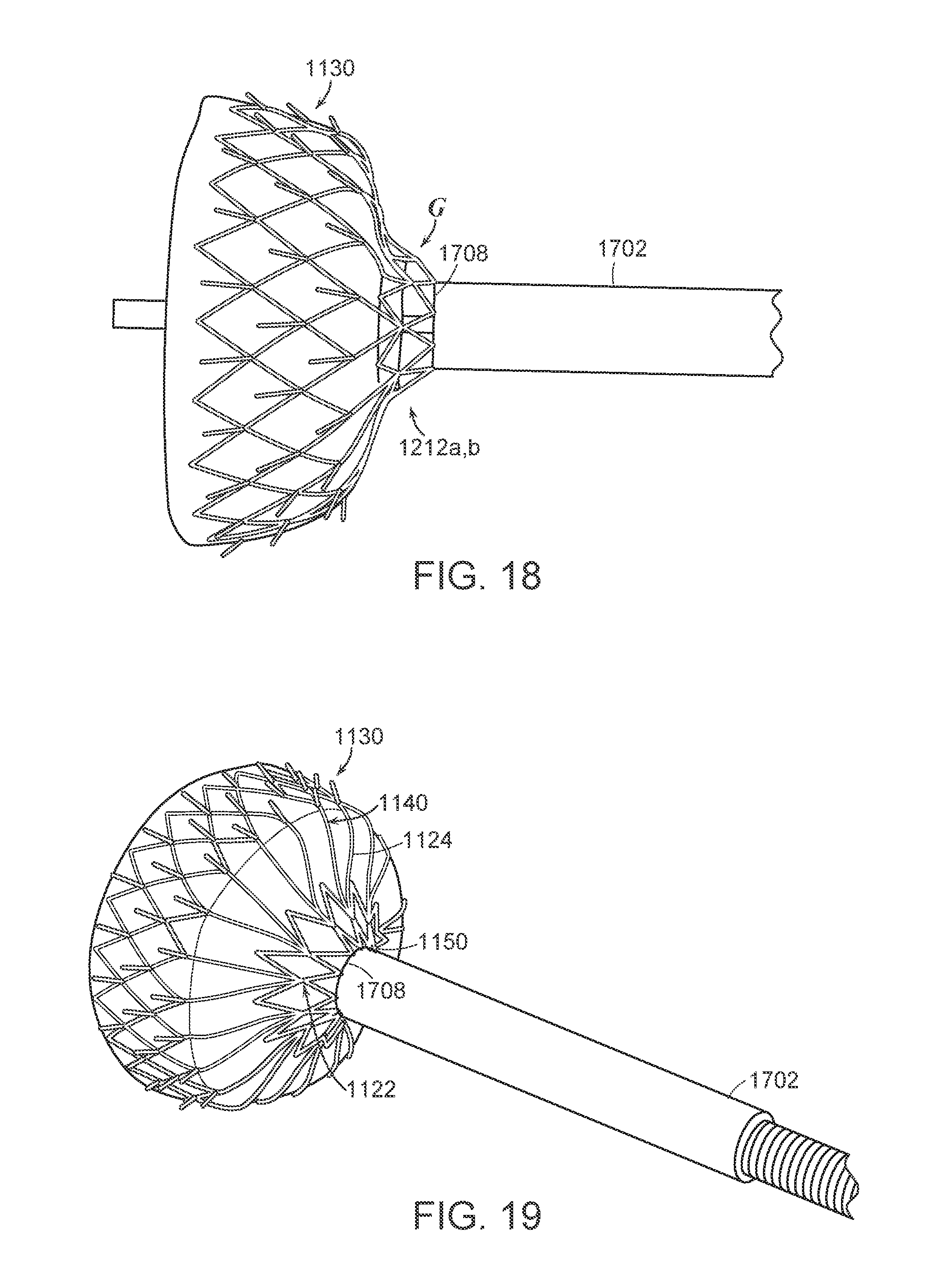
D00017

D00018
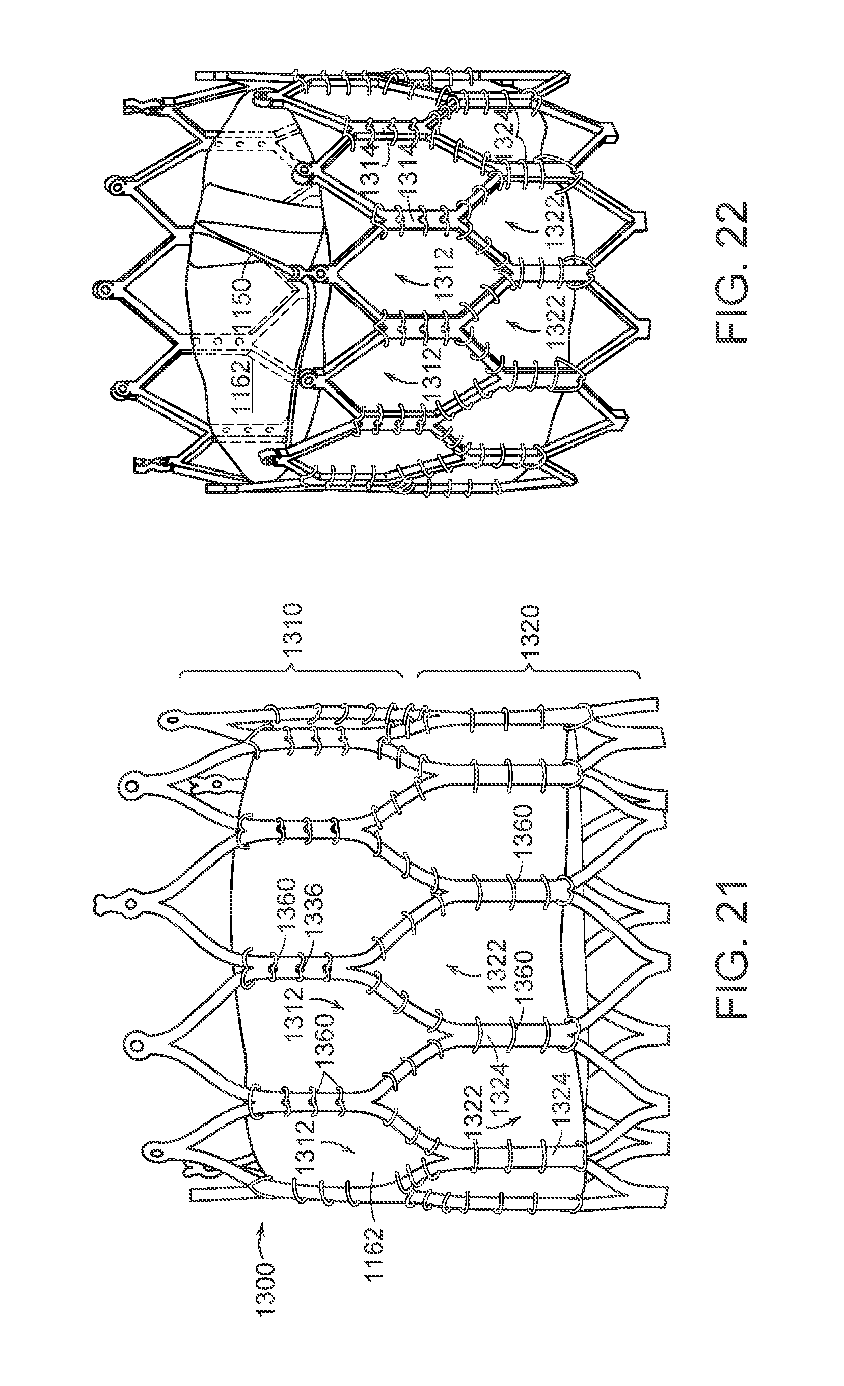
D00019

XML
uspto.report is an independent third-party trademark research tool that is not affiliated, endorsed, or sponsored by the United States Patent and Trademark Office (USPTO) or any other governmental organization. The information provided by uspto.report is based on publicly available data at the time of writing and is intended for informational purposes only.
While we strive to provide accurate and up-to-date information, we do not guarantee the accuracy, completeness, reliability, or suitability of the information displayed on this site. The use of this site is at your own risk. Any reliance you place on such information is therefore strictly at your own risk.
All official trademark data, including owner information, should be verified by visiting the official USPTO website at www.uspto.gov. This site is not intended to replace professional legal advice and should not be used as a substitute for consulting with a legal professional who is knowledgeable about trademark law.