Dynamized interspinal implant
Serhan , et al. O
U.S. patent number 10,433,881 [Application Number 15/787,998] was granted by the patent office on 2019-10-08 for dynamized interspinal implant. This patent grant is currently assigned to DePuy Synthes Products, Inc.. The grantee listed for this patent is DEPUY SYNTHES PRODUCTS, INC.. Invention is credited to William Christianson, Alexander Michel DiNello, Hassan Serhan.


| United States Patent | 10,433,881 |
| Serhan , et al. | October 8, 2019 |
Dynamized interspinal implant
Abstract
An interspinous process having a narrowed distal portion.
| Inventors: | Serhan; Hassan (South Easton, MA), DiNello; Alexander Michel (Palo Alto, CA), Christianson; William (Duxbury, MA) | ||||||||||
|---|---|---|---|---|---|---|---|---|---|---|---|
| Applicant: |
|
||||||||||
| Assignee: | DePuy Synthes Products, Inc.
(Raynham, MA) |
||||||||||
| Family ID: | 34919753 | ||||||||||
| Appl. No.: | 15/787,998 | ||||||||||
| Filed: | October 19, 2017 |
Prior Publication Data
| Document Identifier | Publication Date | |
|---|---|---|
| US 20180036043 A1 | Feb 8, 2018 | |
Related U.S. Patent Documents
| Application Number | Filing Date | Patent Number | Issue Date | ||
|---|---|---|---|---|---|
| 15446554 | Mar 1, 2017 | 9949769 | |||
| 15149132 | May 30, 2017 | 9662149 | |||
| 15149085 | May 30, 2017 | 9662148 | |||
| 15148937 | May 30, 2017 | 9662147 | |||
| 14845687 | Aug 2, 2016 | 9402654 | |||
| 14134090 | Dec 19, 2013 | ||||
| 10793967 | Jan 28, 2014 | 8636802 | |||
| Current U.S. Class: | 1/1 |
| Current CPC Class: | A61B 17/7062 (20130101); A61F 2/4405 (20130101); A61B 17/7068 (20130101); A61B 17/7065 (20130101); A61F 2002/482 (20130101); A61B 2017/681 (20130101); A61B 2017/567 (20130101); A61B 2017/00964 (20130101); A61B 2017/00221 (20130101); A61B 2017/00075 (20130101) |
| Current International Class: | A61B 17/88 (20060101); A61F 2/44 (20060101); A61B 17/70 (20060101); A61F 2/48 (20060101); A61B 17/56 (20060101); A61B 17/68 (20060101); A61B 17/00 (20060101) |
| Field of Search: | ;606/246-249 ;623/17.11,17.13,17.15,17.16 |
References Cited [Referenced By]
U.S. Patent Documents
| 3867728 | February 1975 | Stubstad et al. |
| 4349921 | September 1982 | Kuntz |
| 4714469 | December 1987 | Kenna |
| 4759766 | July 1988 | Buettner-Danz et al. |
| 4759769 | July 1988 | Hedman et al. |
| 4863476 | September 1989 | Shepperd |
| 4871366 | October 1989 | von Recum et al. |
| 4878915 | November 1989 | Brantigan |
| 4911718 | March 1990 | Lee et al. |
| 4932969 | June 1990 | Frey et al. |
| 4946378 | August 1990 | Hirayama et al. |
| 5002576 | March 1991 | Fuhrmann et al. |
| 5024670 | June 1991 | Smith et al. |
| 5030233 | July 1991 | Ducheyne |
| 5071437 | December 1991 | Steffee |
| 5123926 | June 1992 | Pisharodi |
| 5134477 | July 1992 | Knauer et al. |
| 5290312 | March 1994 | Kojimoto et al. |
| 5306308 | April 1994 | Gross et al. |
| 5306309 | April 1994 | Wagner et al. |
| 5314477 | May 1994 | Marnay |
| 5344252 | September 1994 | Kakimoto |
| 5370697 | December 1994 | Baumgartner |
| 5372660 | December 1994 | Davidson et al. |
| 5401269 | March 1995 | Buttner-Janz et al. |
| 5425773 | June 1995 | Boyd |
| 5458641 | October 1995 | Ramirez Jimenez |
| 5458642 | October 1995 | Beer et al. |
| 5458643 | October 1995 | Oka et al. |
| 5507816 | April 1996 | Bullivant |
| 5514180 | May 1996 | Heggeness et al. |
| 5522899 | June 1996 | Michelson |
| 5527312 | June 1996 | Ray |
| 5534029 | July 1996 | Shima |
| 5534030 | July 1996 | Navarro et al. |
| 5554191 | September 1996 | Lahille |
| 5556431 | September 1996 | Buttner-Janz |
| 5562738 | October 1996 | Boyd et al. |
| 5609635 | March 1997 | Michelson |
| 5645596 | July 1997 | Kim et al. |
| 5645599 | July 1997 | Samani |
| 5653763 | August 1997 | Errico et al. |
| 5665122 | September 1997 | Kambin |
| 5674294 | October 1997 | Bainville et al. |
| 5674296 | October 1997 | Bryan et al. |
| 5676701 | October 1997 | Yuan et al. |
| 5683465 | November 1997 | Shinn et al. |
| 5697977 | December 1997 | Pisharodi |
| 5702450 | December 1997 | Bisserie et al. |
| 5716415 | February 1998 | Steffee |
| 5755798 | May 1998 | Papavero et al. |
| 5772661 | June 1998 | Michelson |
| 5782832 | July 1998 | Larsen et al. |
| 5824093 | October 1998 | Ray et al. |
| 5824094 | October 1998 | Serhan et al. |
| 5836948 | November 1998 | Zucherman et al. |
| 5865846 | February 1999 | Bryan et al. |
| 5865848 | February 1999 | Baker |
| 5888224 | March 1999 | Beckers et al. |
| 5888226 | March 1999 | Rogozinski |
| 5893889 | April 1999 | Harrington |
| 5893890 | April 1999 | Pisharodi |
| 5895428 | April 1999 | Berry |
| 5976186 | November 1999 | Bao et al. |
| 5980522 | November 1999 | Koros et al. |
| 5989291 | November 1999 | Ralph et al. |
| 6001130 | December 1999 | Bryan et al. |
| 6019792 | February 2000 | Cauthen |
| 6022350 | February 2000 | Ganem |
| 6039761 | March 2000 | Li et al. |
| 6039763 | March 2000 | Shelokov |
| 6045579 | April 2000 | Hochshuler et al. |
| 6063121 | May 2000 | Xavier et al. |
| 6068630 | May 2000 | Zucherman et al. |
| 6087553 | July 2000 | Cohen et al. |
| 6099531 | August 2000 | Bonutti |
| 6106557 | August 2000 | Robioneck et al. |
| 6113637 | September 2000 | Gill et al. |
| 6113638 | September 2000 | Williams et al. |
| 6126689 | October 2000 | Brett |
| 6127597 | October 2000 | Beyar et al. |
| 6136031 | October 2000 | Middleton |
| 6139579 | October 2000 | Steffee et al. |
| 6146387 | November 2000 | Trott et al. |
| 6146421 | November 2000 | Gordon et al. |
| 6162252 | December 2000 | Kuras et al. |
| 6176882 | January 2001 | Biedermann et al. |
| 6179794 | January 2001 | Burras |
| 6179873 | January 2001 | Zientek |
| 6183517 | February 2001 | Suddaby |
| 6197065 | March 2001 | Martin et al. |
| 6296647 | October 2001 | Robioneck et al. |
| 6302914 | October 2001 | Michelson |
| 6332894 | December 2001 | Stalcup et al. |
| 6332895 | December 2001 | Suddaby |
| 6368350 | April 2002 | Erickson et al. |
| 6375681 | April 2002 | Truscott |
| 6387130 | May 2002 | Stone et al. |
| 6395032 | May 2002 | Gauchet |
| 6409766 | June 2002 | Brett |
| 6413278 | July 2002 | Marchosky |
| 6416551 | July 2002 | Keller |
| 6419706 | July 2002 | Graf |
| 6440169 | August 2002 | Elberg et al. |
| 6447448 | September 2002 | Ishikawa et al. |
| 6454806 | September 2002 | Cohen |
| 6468310 | October 2002 | Ralph et al. |
| 6475639 | November 2002 | Shahinpoor et al. |
| 6488710 | December 2002 | Besselink |
| 6517580 | February 2003 | Ramadan et al. |
| 6527804 | March 2003 | Gauchet et al. |
| 6533818 | March 2003 | Weber et al. |
| 6547823 | April 2003 | Scarborough et al. |
| 6565605 | May 2003 | Goble et al. |
| 6579320 | June 2003 | Gauchet et al. |
| 6582466 | June 2003 | Gauchet |
| 6582468 | June 2003 | Gauchet |
| 6592624 | July 2003 | Fraser et al. |
| 6595998 | July 2003 | Johnson et al. |
| 6607558 | August 2003 | Kuras |
| 6620196 | September 2003 | Trieu |
| 6626943 | September 2003 | Eberlein et al. |
| 6641614 | November 2003 | Wagner et al. |
| 6645248 | November 2003 | Casutt |
| 6648917 | November 2003 | Gerbec et al. |
| 6669732 | December 2003 | Serhan et al. |
| 6676665 | January 2004 | Foley et al. |
| 6682562 | January 2004 | Viart et al. |
| 6706070 | March 2004 | Wagner et al. |
| 6719796 | April 2004 | Cohen et al. |
| 6723126 | April 2004 | Berry |
| 6723127 | April 2004 | Ralph et al. |
| 6733532 | May 2004 | Gauchet et al. |
| 6733535 | May 2004 | Michelson |
| 6740117 | May 2004 | Ralph et al. |
| 6743255 | June 2004 | Ferree |
| 6758861 | July 2004 | Ralph et al. |
| 6770094 | August 2004 | Fehling et al. |
| 6770095 | August 2004 | Grinberg et al. |
| 6793678 | September 2004 | Hawkins |
| 6805714 | October 2004 | Sutcliffe |
| 6835208 | December 2004 | Marchosky |
| 6855167 | February 2005 | Shimp et al. |
| 6863673 | March 2005 | Gerbec et al. |
| 6881229 | April 2005 | Khandkar et al. |
| 6893464 | May 2005 | Kiester |
| 6936071 | August 2005 | Marnay et al. |
| 6953477 | October 2005 | Berry |
| 6955691 | October 2005 | Chae et al. |
| 6964686 | November 2005 | Gordon |
| 6966910 | November 2005 | Ritland |
| 6969404 | November 2005 | Ferree |
| 7018412 | March 2006 | Ferreira et al. |
| 7018416 | March 2006 | Hanson et al. |
| 7022138 | April 2006 | Mashburn |
| 7025787 | April 2006 | Bryan et al. |
| 7037339 | May 2006 | Houfburg |
| 7083650 | August 2006 | Moskowitz et al. |
| 7094257 | August 2006 | Mujwid et al. |
| 7156876 | January 2007 | Moumene et al. |
| 7211112 | May 2007 | Baynham et al. |
| 7217293 | May 2007 | Branch, Jr. |
| 7220280 | May 2007 | Kast et al. |
| 7223292 | May 2007 | Messerli et al. |
| 7226483 | June 2007 | Gerber et al. |
| 7235101 | June 2007 | Berry et al. |
| 7291173 | November 2007 | Richelsoph et al. |
| 7320708 | January 2008 | Bernstein |
| 7326248 | February 2008 | Michelson |
| 7442211 | October 2008 | de Villiers et al. |
| 7503920 | March 2009 | Siegal |
| 7503933 | March 2009 | Michelson |
| 7507241 | March 2009 | Levy et al. |
| 7517363 | April 2009 | Rogers et al. |
| 7569074 | August 2009 | Eisermann et al. |
| 7575599 | August 2009 | Villiers et al. |
| 7618458 | November 2009 | Biedermann et al. |
| 7621950 | November 2009 | Globerman et al. |
| 7621960 | November 2009 | Boyd et al. |
| 7641692 | January 2010 | Bryan et al. |
| 7655010 | February 2010 | Serhan et al. |
| 7691147 | April 2010 | Gutlin et al. |
| 7703727 | April 2010 | Selness |
| 7722612 | May 2010 | Sala et al. |
| 7722674 | May 2010 | Grotz |
| 7731751 | June 2010 | Butler et al. |
| 7744650 | June 2010 | Lindner et al. |
| 7749270 | July 2010 | Peterman |
| 7771473 | August 2010 | Thramann |
| 7789914 | September 2010 | Michelson |
| 7799080 | September 2010 | Doty |
| 7799081 | September 2010 | McKinley |
| 7799083 | September 2010 | Smith et al. |
| 7819921 | October 2010 | Grotz |
| 7824445 | November 2010 | Biro et al. |
| 7837734 | November 2010 | Zucherman et al. |
| 7846206 | December 2010 | Oglaza et al. |
| 7850733 | December 2010 | Baynham et al. |
| 7854766 | December 2010 | Moskowitz et al. |
| 7874980 | January 2011 | Sonnenschein et al. |
| 7879098 | February 2011 | Simmons, Jr. |
| 7887589 | February 2011 | Glenn et al. |
| 7909870 | March 2011 | Kraus |
| 7918874 | April 2011 | Siegal |
| 7922729 | April 2011 | Michelson |
| 7951199 | May 2011 | Miller |
| 7959675 | June 2011 | Gately |
| 7985231 | July 2011 | Sankaran |
| 7993403 | August 2011 | Foley et al. |
| 8016859 | September 2011 | Donofrio et al. |
| 8021424 | September 2011 | Beger et al. |
| 8021426 | September 2011 | Segal et al. |
| 8025697 | September 2011 | McClellan, III et al. |
| 8034109 | October 2011 | Zwirkoski |
| 8043381 | October 2011 | Hestad et al. |
| 8052754 | November 2011 | Froehlich |
| 8057545 | November 2011 | Hughes et al. |
| 8062375 | November 2011 | Glerum et al. |
| 8075621 | December 2011 | Michelson |
| 8097036 | January 2012 | Cordaro et al. |
| 8105382 | January 2012 | Olmos et al. |
| 8177812 | May 2012 | Sankaran |
| 8192495 | June 2012 | Simpson et al. |
| 8202322 | June 2012 | Doty |
| 8216312 | July 2012 | Gray |
| 8216314 | July 2012 | Richelsoph |
| 8221501 | July 2012 | Eisermann et al. |
| 8221502 | July 2012 | Branch, Jr. |
| 8221503 | July 2012 | Garcia et al. |
| 8231681 | July 2012 | Castleman et al. |
| 8236058 | August 2012 | Fabian et al. |
| 8241358 | August 2012 | Butler et al. |
| 8241361 | August 2012 | Link |
| 8257442 | September 2012 | Edie et al. |
| 8262666 | September 2012 | Baynham et al. |
| 8267939 | September 2012 | Cipoletti et al. |
| 8267965 | September 2012 | Gimbel et al. |
| 8273128 | September 2012 | Oh et al. |
| 8287599 | October 2012 | McGuckin, Jr. |
| 8292959 | October 2012 | Webb et al. |
| 8303663 | November 2012 | Jimenez et al. |
| 8323345 | December 2012 | Sledge |
| 8328852 | December 2012 | Zehavi et al. |
| 8337559 | December 2012 | Hansell et al. |
| 8343193 | January 2013 | Johnson et al. |
| 8353961 | January 2013 | McClintock et al. |
| 8361154 | January 2013 | Reo |
| 8366777 | February 2013 | Matthis et al. |
| 8377098 | February 2013 | Landry et al. |
| 8398712 | March 2013 | de Villiers et al. |
| 8398713 | March 2013 | Weiman |
| 8409290 | April 2013 | Zamani et al. |
| 8409291 | April 2013 | Blackwell et al. |
| 8414650 | April 2013 | Bertele et al. |
| 8435298 | May 2013 | Weiman |
| 8454698 | June 2013 | de Villiers et al. |
| 8480715 | July 2013 | Gray |
| 8480742 | July 2013 | Pisharodi |
| 8486148 | July 2013 | Butler et al. |
| 8491659 | July 2013 | Weiman |
| 8506635 | August 2013 | Palmatier et al. |
| 8518087 | August 2013 | Lopez et al. |
| 8518120 | August 2013 | Glerum et al. |
| 8545567 | October 2013 | Krueger |
| 8551173 | October 2013 | Lechmann et al. |
| 8556979 | October 2013 | Glerum et al. |
| 8568481 | October 2013 | Olmos et al. |
| 8579977 | November 2013 | Fabian |
| 8579981 | November 2013 | Lim et al. |
| 8591585 | November 2013 | McLaughlin et al. |
| 8603168 | December 2013 | Gordon et al. |
| 8603177 | December 2013 | Gray |
| 8628576 | January 2014 | Triplett et al. |
| 8628578 | January 2014 | Miller et al. |
| 8632595 | January 2014 | Weiman |
| 8636802 | January 2014 | Serhan et al. |
| 8641764 | February 2014 | Gately |
| 8663329 | March 2014 | Ernst |
| 8668740 | March 2014 | Rhoda et al. |
| 8679183 | March 2014 | Glerum et al. |
| 8685095 | April 2014 | Miller et al. |
| 8685098 | April 2014 | Glerum et al. |
| 8696751 | April 2014 | Ashley et al. |
| 8709086 | April 2014 | Glerum |
| 8715351 | May 2014 | Pinto |
| 8721723 | May 2014 | Hansell et al. |
| 8728166 | May 2014 | Schwab |
| 8753398 | June 2014 | Gordon et al. |
| 8758441 | June 2014 | Hovda et al. |
| 8764806 | July 2014 | Abdou |
| 8771360 | July 2014 | Jimenez et al. |
| 8778025 | July 2014 | Ragab et al. |
| 8795366 | August 2014 | Varela |
| 8795374 | August 2014 | Chee |
| 8801792 | August 2014 | de Villiers et al. |
| 8828085 | September 2014 | Jensen |
| 8845728 | September 2014 | Abdou |
| 8845731 | September 2014 | Weiman |
| 8845732 | September 2014 | Weiman |
| 8852279 | October 2014 | Weiman |
| 8864833 | October 2014 | Glerum et al. |
| 8888853 | November 2014 | Glerum et al. |
| 8888854 | November 2014 | Glerum et al. |
| 8900307 | December 2014 | Hawkins et al. |
| 8936641 | January 2015 | Cain |
| 8940052 | January 2015 | Lechmann et al. |
| 9089428 | July 2015 | Bertele et al. |
| 9095446 | August 2015 | Landry et al. |
| 9095447 | August 2015 | Barreiro et al. |
| 9387087 | July 2016 | Tyber |
| 9402654 | August 2016 | Serhan |
| 9414923 | August 2016 | Studer et al. |
| 9662147 | May 2017 | Serhan |
| 9662148 | May 2017 | Serhan |
| 9662149 | May 2017 | Serhan et al. |
| 9668785 | June 2017 | Serhan et al. |
| 9724207 | August 2017 | DiMauro et al. |
| 9949769 | April 2018 | Serhan et al. |
| 2001/0018614 | August 2001 | Bianchi |
| 2001/0056302 | December 2001 | Boyer et al. |
| 2002/0010070 | January 2002 | Cales et al. |
| 2002/0029084 | March 2002 | Paul et al. |
| 2002/0032483 | March 2002 | Nicholson et al. |
| 2002/0035400 | March 2002 | Bryan et al. |
| 2002/0037799 | March 2002 | Li et al. |
| 2002/0039620 | April 2002 | Shahinpoor et al. |
| 2002/0068976 | June 2002 | Jackson |
| 2002/0068977 | June 2002 | Jackson |
| 2002/0128715 | September 2002 | Bryan et al. |
| 2002/0128716 | September 2002 | Cohen et al. |
| 2002/0151976 | October 2002 | Foley et al. |
| 2002/0165612 | November 2002 | Gerber et al. |
| 2003/0004575 | January 2003 | Erickson |
| 2003/0004576 | January 2003 | Thalgott |
| 2003/0006942 | January 2003 | Searls et al. |
| 2003/0014112 | January 2003 | Ralph et al. |
| 2003/0014116 | January 2003 | Ralph et al. |
| 2003/0023305 | January 2003 | McKay |
| 2003/0028251 | February 2003 | Mathews |
| 2003/0039620 | February 2003 | Rodriguez et al. |
| 2003/0040799 | February 2003 | Boyd et al. |
| 2003/0045939 | March 2003 | Casutt |
| 2003/0065396 | April 2003 | Michelson |
| 2003/0069642 | April 2003 | Ralph et al. |
| 2003/0078667 | April 2003 | Manasas et al. |
| 2003/0130739 | July 2003 | Gerbec et al. |
| 2003/0135275 | July 2003 | Garcia et al. |
| 2003/0135277 | July 2003 | Bryan et al. |
| 2003/0139812 | July 2003 | Garcia et al. |
| 2003/0139813 | July 2003 | Messerli et al. |
| 2003/0204261 | October 2003 | Eisermann et al. |
| 2003/0233145 | December 2003 | Landry et al. |
| 2004/0002761 | January 2004 | Rogers et al. |
| 2004/0010318 | January 2004 | Ferree |
| 2004/0030387 | February 2004 | Landry et al. |
| 2004/0049188 | March 2004 | Slivka et al. |
| 2004/0064144 | April 2004 | Johnson et al. |
| 2004/0073310 | April 2004 | Moumene et al. |
| 2004/0087947 | May 2004 | Lim |
| 2004/0088055 | May 2004 | Hanson et al. |
| 2004/0127991 | July 2004 | Ferree |
| 2004/0133279 | July 2004 | Krueger et al. |
| 2004/0143332 | July 2004 | Krueger et al. |
| 2004/0153065 | August 2004 | Lim |
| 2004/0153156 | August 2004 | Cohen et al. |
| 2004/0162618 | August 2004 | Mujwid et al. |
| 2004/0172133 | September 2004 | Gerber et al. |
| 2004/0186570 | September 2004 | Rapp |
| 2004/0186577 | September 2004 | Ferree |
| 2004/0193273 | September 2004 | Huang |
| 2004/0193277 | September 2004 | Long et al. |
| 2004/0243238 | December 2004 | Amin et al. |
| 2004/0249462 | December 2004 | Huang |
| 2004/0267367 | December 2004 | O'Neil |
| 2005/0019365 | January 2005 | Frauchiger et al. |
| 2005/0038515 | February 2005 | Kunzler |
| 2005/0113916 | May 2005 | Branch |
| 2005/0113917 | May 2005 | Chae et al. |
| 2005/0119752 | June 2005 | Williams et al. |
| 2005/0125062 | June 2005 | Biedermann et al. |
| 2005/0165485 | July 2005 | Trieu |
| 2005/0197702 | September 2005 | Coppes et al. |
| 2005/0203624 | September 2005 | Serhan et al. |
| 2005/0222681 | October 2005 | Richley et al. |
| 2005/0256576 | November 2005 | Moskowitz et al. |
| 2005/0261769 | November 2005 | Moskowitz et al. |
| 2005/0278026 | December 2005 | Gordon et al. |
| 2006/0004431 | January 2006 | Fuller et al. |
| 2006/0058876 | March 2006 | McKinley |
| 2006/0058880 | March 2006 | Wysocki et al. |
| 2006/0100706 | May 2006 | Shadduck et al. |
| 2006/0111785 | May 2006 | O'Neil |
| 2006/0122701 | June 2006 | Kiester |
| 2006/0122703 | June 2006 | Aebi et al. |
| 2006/0136062 | June 2006 | DiNello et al. |
| 2006/0142858 | June 2006 | Colleran et al. |
| 2006/0206207 | September 2006 | Dryer et al. |
| 2006/0235531 | October 2006 | Buettner-Danz |
| 2006/0253201 | November 2006 | McLuen |
| 2006/0265075 | November 2006 | Baumgartner et al. |
| 2006/0265077 | November 2006 | Zwirkoski |
| 2006/0293753 | December 2006 | Thramann |
| 2007/0010886 | January 2007 | Banick et al. |
| 2007/0055377 | March 2007 | Hanson et al. |
| 2007/0118222 | May 2007 | Lang |
| 2007/0149978 | June 2007 | Shezifi et al. |
| 2007/0173939 | July 2007 | Kim et al. |
| 2007/0173940 | July 2007 | Hestad et al. |
| 2007/0178222 | August 2007 | Storey et al. |
| 2007/0191959 | August 2007 | Hartmann et al. |
| 2007/0198089 | August 2007 | Moskowitz et al. |
| 2007/0208423 | September 2007 | Messerli et al. |
| 2007/0219634 | September 2007 | Greenhalgh et al. |
| 2007/0233244 | October 2007 | Lopez et al. |
| 2007/0270968 | November 2007 | Baynham et al. |
| 2007/0272259 | November 2007 | Allard et al. |
| 2007/0276375 | November 2007 | Rapp |
| 2007/0299521 | December 2007 | Glenn et al. |
| 2008/0009877 | January 2008 | Sankaran et al. |
| 2008/0015701 | January 2008 | Garcia et al. |
| 2008/0021556 | January 2008 | Edie |
| 2008/0021558 | January 2008 | Thramann |
| 2008/0027550 | January 2008 | Link et al. |
| 2008/0033440 | February 2008 | Moskowitz et al. |
| 2008/0051902 | February 2008 | Dwyer |
| 2008/0058944 | March 2008 | Duplessis et al. |
| 2008/0065219 | March 2008 | Dye |
| 2008/0082173 | April 2008 | Delurio et al. |
| 2008/0132934 | June 2008 | Reiley et al. |
| 2008/0133017 | June 2008 | Beyar et al. |
| 2008/0140085 | June 2008 | Gately et al. |
| 2008/0140207 | June 2008 | Olmos et al. |
| 2008/0147193 | June 2008 | Matthis et al. |
| 2008/0161927 | July 2008 | Savage et al. |
| 2008/0167657 | July 2008 | Greenhalgh |
| 2008/0177388 | July 2008 | Patterson et al. |
| 2008/0183204 | July 2008 | Greenhalgh et al. |
| 2008/0195209 | August 2008 | Garcia et al. |
| 2008/0228225 | September 2008 | Trautwein et al. |
| 2008/0243251 | October 2008 | Stad et al. |
| 2008/0243254 | October 2008 | Butler |
| 2008/0249622 | October 2008 | Gray |
| 2008/0281425 | November 2008 | Thalgott et al. |
| 2009/0005873 | January 2009 | Slivka et al. |
| 2009/0030423 | January 2009 | Puno |
| 2009/0054991 | February 2009 | Biyani et al. |
| 2009/0069895 | March 2009 | Gittings et al. |
| 2009/0076610 | March 2009 | Afzal |
| 2009/0099568 | April 2009 | Lowry et al. |
| 2009/0112320 | April 2009 | Kraus |
| 2009/0112324 | April 2009 | Refai et al. |
| 2009/0164020 | June 2009 | Janowski et al. |
| 2009/0177281 | July 2009 | Swanson et al. |
| 2009/0177284 | July 2009 | Rogers et al. |
| 2009/0222096 | September 2009 | Trieu |
| 2009/0222099 | September 2009 | Liu et al. |
| 2009/0234398 | September 2009 | Chirico et al. |
| 2009/0240335 | September 2009 | Arcenio et al. |
| 2009/0248159 | October 2009 | Aflatoon |
| 2009/0248163 | October 2009 | King et al. |
| 2009/0276051 | November 2009 | Arramon et al. |
| 2009/0292361 | November 2009 | Lopez |
| 2010/0016905 | January 2010 | Greenhalgh et al. |
| 2010/0042218 | February 2010 | Nebosky et al. |
| 2010/0076559 | March 2010 | Bagga et al. |
| 2010/0094426 | April 2010 | Grohowski, Jr. et al. |
| 2010/0179594 | July 2010 | Theofilos et al. |
| 2010/0211182 | August 2010 | Zimmermann |
| 2010/0234956 | September 2010 | Attia et al. |
| 2010/0262240 | October 2010 | Chavatte et al. |
| 2010/0286783 | November 2010 | Lechmann et al. |
| 2010/0324607 | December 2010 | Davis |
| 2011/0004308 | January 2011 | Marino et al. |
| 2011/0004310 | January 2011 | Michelson |
| 2011/0015747 | January 2011 | McManus et al. |
| 2011/0029082 | February 2011 | Hall |
| 2011/0035011 | February 2011 | Cain |
| 2011/0082552 | April 2011 | Wistrom et al. |
| 2011/0093074 | April 2011 | Glerum et al. |
| 2011/0093076 | April 2011 | Reo et al. |
| 2011/0130835 | June 2011 | Ashley et al. |
| 2011/0130838 | June 2011 | Morgenstern Lopez |
| 2011/0144753 | June 2011 | Marchek et al. |
| 2011/0159070 | June 2011 | Jin et al. |
| 2011/0172716 | July 2011 | Glerum |
| 2011/0270261 | November 2011 | Mast et al. |
| 2011/0282453 | November 2011 | Greenhalgh et al. |
| 2011/0301711 | December 2011 | Palmatier et al. |
| 2011/0301712 | December 2011 | Palmatier et al. |
| 2012/0004726 | January 2012 | Greenhalgh et al. |
| 2012/0004732 | January 2012 | Goel et al. |
| 2012/0022654 | January 2012 | Farris et al. |
| 2012/0029636 | February 2012 | Ragab et al. |
| 2012/0071977 | March 2012 | Oglaza et al. |
| 2012/0071980 | March 2012 | Purcell et al. |
| 2012/0083889 | April 2012 | Purcell et al. |
| 2012/0123546 | May 2012 | Medina |
| 2012/0136443 | May 2012 | Wenzel |
| 2012/0197403 | August 2012 | Merves |
| 2012/0226357 | September 2012 | Varela |
| 2012/0277869 | November 2012 | Siccardi et al. |
| 2012/0290097 | November 2012 | Cipoletti et al. |
| 2012/0310350 | December 2012 | Farris et al. |
| 2012/0310352 | December 2012 | DiMauro et al. |
| 2013/0030536 | January 2013 | Rhoda et al. |
| 2013/0030544 | January 2013 | Studer |
| 2013/0060337 | March 2013 | Petersheim et al. |
| 2013/0073044 | March 2013 | Gamache |
| 2013/0085572 | April 2013 | Glerum et al. |
| 2013/0085574 | April 2013 | Sledge |
| 2013/0110240 | May 2013 | Hansell et al. |
| 2013/0116791 | May 2013 | Theofilos |
| 2013/0123924 | May 2013 | Butler et al. |
| 2013/0123927 | May 2013 | Malandain |
| 2013/0138214 | May 2013 | Greenhalgh et al. |
| 2013/0144387 | June 2013 | Walker et al. |
| 2013/0144388 | June 2013 | Emery et al. |
| 2013/0158663 | June 2013 | Miller et al. |
| 2013/0158664 | June 2013 | Palmatier et al. |
| 2013/0158667 | June 2013 | Tabor et al. |
| 2013/0158668 | June 2013 | Nichols et al. |
| 2013/0158669 | June 2013 | Sungarian et al. |
| 2013/0173004 | July 2013 | Greenhalgh et al. |
| 2013/0190876 | July 2013 | Drochner et al. |
| 2013/0190877 | July 2013 | Medina |
| 2013/0204371 | August 2013 | McLuen et al. |
| 2013/0211525 | August 2013 | McLuen et al. |
| 2013/0211526 | August 2013 | Alheidt et al. |
| 2013/0218276 | August 2013 | Fiechter et al. |
| 2013/0253585 | September 2013 | Garcia et al. |
| 2013/0261746 | October 2013 | Linares et al. |
| 2013/0310939 | November 2013 | Fabian et al. |
| 2014/0039622 | February 2014 | Glerum et al. |
| 2014/0046333 | February 2014 | Johnson et al. |
| 2014/0058513 | February 2014 | Gahman et al. |
| 2014/0067073 | March 2014 | Hauck |
| 2014/0086962 | March 2014 | Jin et al. |
| 2014/0107704 | April 2014 | Serhan et al. |
| 2014/0114414 | April 2014 | Abdou et al. |
| 2014/0114423 | April 2014 | Suedkamp et al. |
| 2014/0128977 | May 2014 | Glerum et al. |
| 2014/0128980 | May 2014 | Kirschman |
| 2014/0135934 | May 2014 | Hansell et al. |
| 2014/0142706 | May 2014 | Hansell et al. |
| 2014/0163683 | June 2014 | Seifert et al. |
| 2014/0172106 | June 2014 | To et al. |
| 2014/0180421 | June 2014 | Glerum et al. |
| 2014/0188225 | July 2014 | Dmuschewsky |
| 2014/0249629 | September 2014 | Moskowitz et al. |
| 2014/0249630 | September 2014 | Weiman |
| 2014/0257484 | September 2014 | Flower et al. |
| 2014/0257486 | September 2014 | Alheidt |
| 2014/0257494 | September 2014 | Thorwarth et al. |
| 2014/0277476 | September 2014 | McLean et al. |
| 2014/0303731 | October 2014 | Glerum |
| 2014/0303732 | October 2014 | Rhoda et al. |
| 2014/0324171 | October 2014 | Glerum et al. |
| 2015/0088256 | March 2015 | Ballard |
| 2015/0238324 | August 2015 | Nebosky et al. |
| 2015/0374992 | December 2015 | Crosby et al. |
| 2016/0000476 | January 2016 | Serhan et al. |
| 2016/0038301 | February 2016 | Wickham |
| 2016/0058573 | March 2016 | DiMauro et al. |
| 2016/0067055 | March 2016 | Hawkins et al. |
| 2016/0074170 | March 2016 | Rogers et al. |
| 2016/0074175 | March 2016 | O'Neil |
| 2016/0100954 | April 2016 | Rumi et al. |
| 2016/0128843 | May 2016 | Tsau et al. |
| 2016/0249958 | September 2016 | Serhan et al. |
| 2016/0249959 | September 2016 | Serhan et al. |
| 2016/0249960 | September 2016 | Serhan et al. |
| 2016/0317714 | November 2016 | DiMauro et al. |
| 2016/0331415 | November 2016 | Serhan et al. |
| 2017/0172632 | June 2017 | Serhan et al. |
| 2018/0271565 | September 2018 | Serhan et al. |
| 101909548 | Dec 2010 | CN | |||
| 28 04 936 | Aug 1979 | DE | |||
| 39 11 610 | Oct 1990 | DE | |||
| 40 12 622 | Jul 1991 | DE | |||
| 197 10 392 | Jul 1999 | DE | |||
| 20 2008 001 079 | Mar 2008 | DE | |||
| 0 282 161 | Sep 1988 | EP | |||
| 0 678 489 | Oct 1995 | EP | |||
| 1 290 985 | Mar 2003 | EP | |||
| 1 385 449 | Feb 2004 | EP | |||
| 1 532 949 | May 2005 | EP | |||
| 1 541 096 | Jun 2005 | EP | |||
| 1 285 449 | Jul 2006 | EP | |||
| 1 683 593 | Jul 2006 | EP | |||
| 1 698 305 | Aug 2007 | EP | |||
| 1 843 723 | Mar 2010 | EP | |||
| 2 368 529 | Sep 2011 | EP | |||
| 2 237 748 | Sep 2012 | EP | |||
| 2 641 571 | Sep 2013 | EP | |||
| 2 764 851 | Aug 2014 | EP | |||
| 2 718 635 | Oct 1995 | FR | |||
| 2 730 159 | Aug 1996 | FR | |||
| 2 874 814 | Mar 2006 | FR | |||
| 2003-526457 | Sep 2003 | JP | |||
| 2006-516456 | Jul 2006 | JP | |||
| 2011-509766 | Mar 2011 | JP | |||
| 94/04100 | Mar 1994 | WO | |||
| 95/31158 | Nov 1995 | WO | |||
| 97/00054 | Jan 1997 | WO | |||
| 99/53871 | Oct 1999 | WO | |||
| 00/13620 | Mar 2000 | WO | |||
| 00/53127 | Sep 2000 | WO | |||
| 00/74605 | Dec 2000 | WO | |||
| 01/01893 | Jan 2001 | WO | |||
| 01/01895 | Jan 2001 | WO | |||
| 01/17464 | Mar 2001 | WO | |||
| 2005/039455 | May 2005 | WO | |||
| 2005/112834 | Dec 2005 | WO | |||
| 2006/047587 | May 2006 | WO | |||
| 2006/058281 | Jun 2006 | WO | |||
| 2006/065419 | Jun 2006 | WO | |||
| 2006/081843 | Aug 2006 | WO | |||
| 2007/009107 | Jan 2007 | WO | |||
| 2007/028098 | Mar 2007 | WO | |||
| 2007/048012 | Apr 2007 | WO | |||
| 2007/084427 | Jul 2007 | WO | |||
| 2008/044057 | Apr 2008 | WO | |||
| 2009/064787 | May 2009 | WO | |||
| 2009/092102 | Jul 2009 | WO | |||
| 2009/124269 | Oct 2009 | WO | |||
| 2009/143496 | Nov 2009 | WO | |||
| 2010/068725 | Jun 2010 | WO | |||
| 2010/088766 | Aug 2010 | WO | |||
| 2010/148112 | Dec 2010 | WO | |||
| 2011/046459 | Apr 2011 | WO | |||
| 2011/046460 | Apr 2011 | WO | |||
| 2011/119617 | Sep 2011 | WO | |||
| 2011/142761 | Nov 2011 | WO | |||
| 2012/009152 | Jan 2012 | WO | |||
| 2012/028182 | Mar 2012 | WO | |||
| 2012/030331 | Mar 2012 | WO | |||
| 2012/089317 | Jul 2012 | WO | |||
| 2012/135764 | Oct 2012 | WO | |||
| 2013/006669 | Jan 2013 | WO | |||
| 2013/023096 | Feb 2013 | WO | |||
| 2013/025876 | Feb 2013 | WO | |||
| 2013/043850 | Mar 2013 | WO | |||
| 2013/082184 | Jun 2013 | WO | |||
| 2013/158294 | Oct 2013 | WO | |||
| 2013/173767 | Nov 2013 | WO | |||
| 2013/184946 | Dec 2013 | WO | |||
| 2014/014610 | Jan 2014 | WO | |||
| 2014/018098 | Jan 2014 | WO | |||
| 2014/026007 | Feb 2014 | WO | |||
| 2014/035962 | Mar 2014 | WO | |||
| 2014/088521 | Jun 2014 | WO | |||
| 2014/116891 | Jul 2014 | WO | |||
| 2015/048997 | Apr 2015 | WO | |||
Other References
|
**[No Author Listed] Link SB Chante--Intervertebral Prosthesis, Brochure, Waldemar Link GmbH & Co., 1988, 29 pages. cited by applicant . **[No Author Listed] Porocoat.RTM. Porous Coating, Depuy Synthes Companies, 2015, 2 pages, webpage, accessed Jul. 5, 2016, <https://emea.depuysynthes.com/hcp/hip/products/qs/porocoat-porous-coa- ting-emea>. cited by applicant . **[No Author Listed] Porocoat.RTM. Porous Coating, Depuy Synthes Companies, 2017, 2 pages, webpage, accessed Jul. 31, 2017, <https://emea.depuysynthes.com/hcp/hip/products/qs/porocoat-porous-coa- ting-emea>. cited by applicant . **[No Author Listed] Spine Solutions --The non-fusion technology company, Brochure, Prodisc, Spine Solutions, Inc., 2001, 16 pages. cited by applicant . **Cheng, B.C., Ph.D., Biomechanical pullout strength and histology of Plasmapore.RTM. XP coated implants: Ovine multi time point survival study. Aesculap Implant Systems, LLC, 2013, 12 pages. cited by applicant . **Chiang, et al., Biomechanical Comparison of Instrumented Posterior Lumbar Interbody Fusion with One or Two Cages by Finite Element Analysis, Spine, 2006, pp. E682-E689, vol. 31 (19), Lippincott Williams & Wilkins, Inc. cited by applicant . **European Search Report EP03253921.5, dated Nov. 13, 2003, 4 pages. cited by applicant . **Tolman, et al., Posterior Lumbar Interbody Fusion for Degenerative Disc Disease Using a Minimally Invasive B-Twin Expandable Spinal Spacer, Journal of Spinal Disorders & Techniques, 2003, pp. 455-460, vol. 16(5). cited by applicant . **Gore, Technique of Cervical Interbody Fusion, Clinical Orthopaedics and Related Research, 1984, pp. 191-195, No. 188. cited by applicant . **Hoagland, T., et al., Total Lumbar Intervertebral Disc Replacement: Testing of a New Articulating Space in Human Cadaver Spines--24th Annual ORS, Dallas, TX, Feb. 21-23, 1978, 8 pages. cited by applicant . **Hunt, et al., Expandable cage placement via a posterolateral approach in lumbar spine reconstructions, Journal of Neurosurgery: Spine, 2006, pp. 271-274, vol. 5. cited by applicant . **International Patent Application No. PCT /US2013/029014, International Search Report dated Jul. 1, 2013, 2 pages. cited by applicant . **Kotsias, A., Clinical trial of titanium-coated PEEL cages anterior cervical discectomy and fusion. [Klinishe Untersuching zum Einsatz von titanbeschichteten Polyetheretherketon-Implantaten bei der cervikalen interkorporalen fusion]. Doctoral thesis. Department of Medicine, Charite, University of Medicine Berlin, 2014, 73 pages. German language document. cited by applicant . **Krbec, et al., [Replacement of the vertebral body with an expansion implant (Synex)], Acta Chir Orthop Traumatal Cech, 2002, pp. 158-162, vol. 69(3). Article in Czech. English Abstract Only. cited by applicant . **Polikeit, et al., The importance of the end plate for interbody cages in the lumbar spine, Eur Spine J, 2003, pp. 556-561, vol. 12. cited by applicant . **Shin, et al., Posterior Lumbar Interbody Fusion via a Unilateral Approach, Yonsei Medical Journal, 2006, pp. 319-325, vol. 47(3). cited by applicant . U.S. Appl. No. 15/927,512, filed Mar. 21, 2018, Dynamized Interspinal Implant. cited by applicant. |
Primary Examiner: Philogene; Pedro
Assistant Examiner: Comstock; David C
Attorney, Agent or Firm: Nutter McClennen & Fish LLP
Parent Case Text
CROSS-REFERENCE TO RELATED APPLICATIONS
This application is a continuation of U.S. application Ser. No. 15/446,554, filed on Mar. 1, 2017, which is a continuation of U.S. application Ser. No. 15/149,132, filed on May 8, 2016 (now U.S. Pat. No. 9,662,149), which is a continuation of U.S. application Ser. No. 15/149,085, filed on May 7, 2016 (now U.S. Pat. No. 9,662,148), which is a continuation of U.S. application Ser. No. 15/148,937, filed on May 6, 2016 (now U.S. Pat. No. 9,662,147), which is a continuation of U.S. application Ser. No. 14/845,687, filed on Sep. 4, 2015 (now U.S. Pat. No. 9,402,654), which is a continuation of U.S. application Ser. No. 14/134,090, filed on Dec. 19, 2013 (now abandoned), which is a division of U.S. application Ser. No. 10/793,967, filed on Mar. 6, 2004 (now U.S. Pat. No. 8,636,802), each of which is hereby incorporated by reference in its entirety.
Claims
We claim:
1. A surgical method, comprising: inserting an intervertebral device between upper and lower vertebrae such that: an upper surface of an upper portion of the device bears against the upper vertebra; teeth extending from the upper portion of the device grip the upper vertebra; a lower surface of a lower portion of the device bears against the lower vertebra; teeth extending from the lower portion of the device grip the lower vertebra; wherein the upper and lower portions of the device extend in a non-parallel manner in an anterior-posterior direction; wherein the device includes a wall disposed between the upper and lower surfaces; inserting an upper bone fastener through a hole formed in an upper extension of the device that extends above the upper surface, the bone fastener extending into a lateral-facing surface of the upper vertebra; and inserting a lower bone fastener through a hole formed in a lower extension of the device that extends beneath the lower surface, the bone fastener extending into a lateral-facing surface of the lower vertebra.
2. The method of claim 1, wherein a height between a posterior end of the upper surface of the upper portion and a posterior end of the lower surface of the lower portion is adapted to change after the device is inserted.
3. The method of claim 1, wherein the device has a height that narrows in an anterior-posterior direction.
4. The method of claim 1, wherein a length of the device is at least twice a width of the device.
5. The method of claim 1, wherein a first dimension of the device selected from length and width in a plane transverse to the spinal axis is at least twice as great as a second dimension of the device selected from length and width in the plane transverse to the spinal axis.
6. The method of claim 1, wherein the length of the upper extension is less than the length of the upper portion.
7. The method of claim 1, wherein the thickness of the wall is greater than the thickness of the upper portion.
8. The method of claim 1, wherein a posterior edge of the upper extension and a posterior edge of the lower extension lie substantially in a common plane.
9. A surgical method, comprising: inserting an intervertebral device between upper and lower vertebrae such that: an upper surface of an upper portion of the device bears against the upper vertebra; teeth extending from the upper portion of the device grip the upper vertebra; a lower surface of a lower portion of the device bears against the lower vertebra; teeth extending from the lower portion of the device grip the lower vertebra; wherein the device includes a wall disposed between the upper and lower surfaces; inserting an upper bone fastener through a hole formed in an upper extension of the device that extends above the upper surface, the bone fastener extending into a lateral-facing surface of the upper vertebra; inserting a lower bone fastener through a hole formed in a lower extension of the device that extends beneath the lower surface, the bone fastener extending into a lateral-facing surface of the lower vertebra; and after inserting the device, changing a height of the device defined between a posterior end of the upper surface of the upper portion and a posterior end of the lower surface of the lower portion.
10. The method of claim 9, wherein the upper and lower portions of the device extend in a non-parallel manner in a first direction.
11. The method of claim 10, wherein the lower bone fastener has a longitudinal axis extending substantially transversely from the first direction.
12. The method of claim 9, wherein a posterior edge of the upper extension and a posterior edge of the lower extension lie substantially in a common plane.
Description
BACKGROUND OF THE INVENTION
The leading cause of lower back pain arises from rupture or degeneration of lumbar intervertebral discs. Pain in the lower extremities is caused by the compression of spinal nerve roots by a bulging disc, while lower back pain is caused by collapse of the disc and by the adverse effects of articulation weight through a damaged, unstable vertebral joint.
In some cases, when a patient having a collapsed disc moves in extension (e.g., leans backward), the posterior portion of the annulus fibrosis or folding of the ligamentum flavum may further compress and extend into the spinal canal. This condition, called "spinal stenosis", narrows the spinal canal and causes impingement of tissue upon the spinal cord, thereby producing pain.
There have been numerous attempts to provide relief for these afflictions by providing a spacer that inserts between adjacent spinous processes present in the posterior portion of the spinal column. This spacer essentially lifts the upper spinous process off of the lower spinous process, thereby relieving stenosis. In general, these interspinous implants are adapted to allow flexion movement in the patient, but resist or limit extension.
U.S. Pat. No. 6,068,630 ("Zuchermann") discloses a spinal distraction implant that alleviates pain associated with spinal stenosis by expanding the volume in the spinal canal or neural foramen. Zuchermann discloses a plurality of implants having a body portion and lateral wings. The body portion is adapted to seat between the adjacent spinous processes, while the wings are adapted to prevent lateral movement of the body portion, thereby holding it in place between the adjacent spinous processes.
U.S. Pat. No. 5,645,599 ("Samani") attempts to relieve spinal stenosis by essentially inserting a flexible horseshoe-shaped device between the adjacent spinous processes. Although the Samani device desirably provides a self-limiting flexibility, it nonetheless suffers from some inadequacies. For example, the Samani device does not provide for natural physiologic rotational movement, nor for post-operative adjustment. In addition, the Samani device discloses the insertion of a bearing cushion, and the adhesive bonding of the bearing cushion to the horseshoe element. However, it is believed that mere adhesive bonding of these elements would cause the cushion to be prone to migration.
SUMMARY OF THE INVENTION
The present inventors have developed a number of flexible interspinous devices having a number of desirable features providing improved performance over conventional solutions.
In a first embodiment, the device has a flexible anterior wall having a narrowed portion. The narrowed portion allows the device to twist in response to spinal rotation, thereby more closely mimicking natural physiologic movement.
Therefore, in accordance with the first embodiment of the present invention, there is provided an interspinous implant for insertion between adjacent spinous processes, the implant comprising:
a) a flexible body comprising:
i) an upper posterior portion having an upper surface adapted to bear upon an upper spinous process, ii) a lower posterior portion having a lower surface adapted to bear upon a lower spinous process, and iii) an arcuate, flexible anterior wall connecting the upper and lower portions, wherein the anterior wall has a narrowed portion.
In a second embodiment, the device has a cushion portion interdigitated with each of the upper and lower bearing portions. Because the cushion portion is interdigitated with these elements, a tenacious bond is provided and migration concerns are alleviated.
Therefore, in accordance with the second embodiment of the present invention, there is provided an interspinous implant for insertion between adjacent spinous processes, the implant comprising:
a) a flexible body comprising:
i) an upper posterior portion having an upper surface adapted to bear upon an upper spinous process, ii) a lower posterior portion having a lower surface adapted to bear upon a lower spinous process, iii) an arcuate, flexible anterior wall connecting the upper and lower portions, and b) a cushion element having an upper surface and a lower surface, wherein the lower surface of the upper portion of the flexible body comprises a porous coating thereon, and wherein the upper surface of the cushion element is interdigitated with the porous coating.
In a third embodiment, the device is adapted to be post-operatively adjustable. The adjustability allows the device to respond to an altered physiologic state, such as an increased collapse of the disc space or decreased patient flexibility, by adjusting the overall stiffness of the implant.
Therefore, in accordance with the third embodiment of the present invention, there is provided an interspinous implant for insertion between adjacent spinous processes, the implant comprising:
a) a flexible body comprising:
i) an upper posterior portion having an upper surface adapted to bear upon an upper spinous process, ii) a lower posterior portion having a lower surface adapted to bear upon a lower spinous process, iii) an arcuate, flexible anterior wall connecting the upper and lower posterior portions, and iv) means for adjusting the stiffness of the implant.
DESCRIPTION OF THE FIGURES
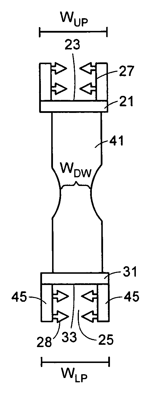
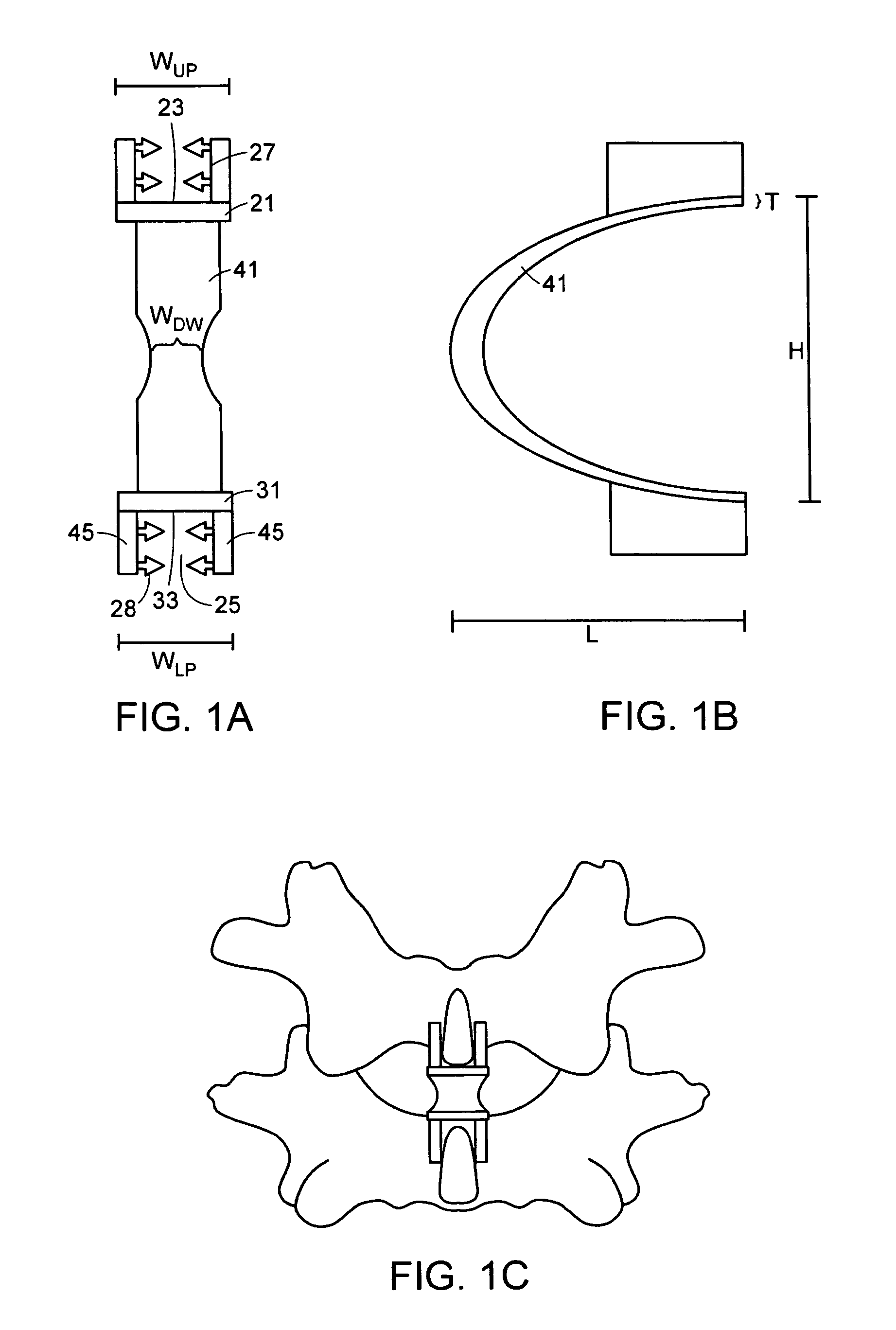
FIG. 1a is a posterior view of the first embodiment of the interspinous implant in the coronal plane
FIG. 1b is a side view of the first embodiment of the interspinous implant in the saggital plane.
FIG. 1c is a posterior view of the first embodiment of the interspinous implant implanted between adjacent vertebrae.
FIG. 2a is a posterior view of the second embodiment of the interspinous implant.
FIG. 2b is a side view of the second embodiment of the interspinous implant in the saggital plane.
FIG. 2c is a side view of an embodiment of the interspinous implant implanted between adjacent vertebrae.
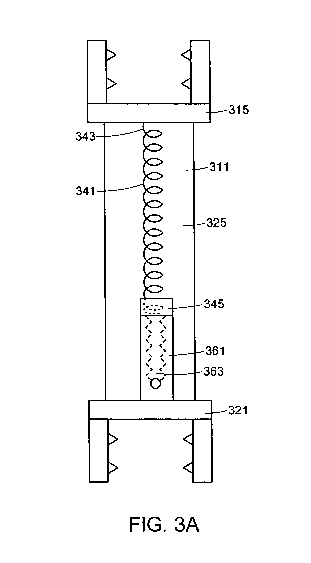
FIG. 3a is a posterior view of the third embodiment of the interspinous implant.
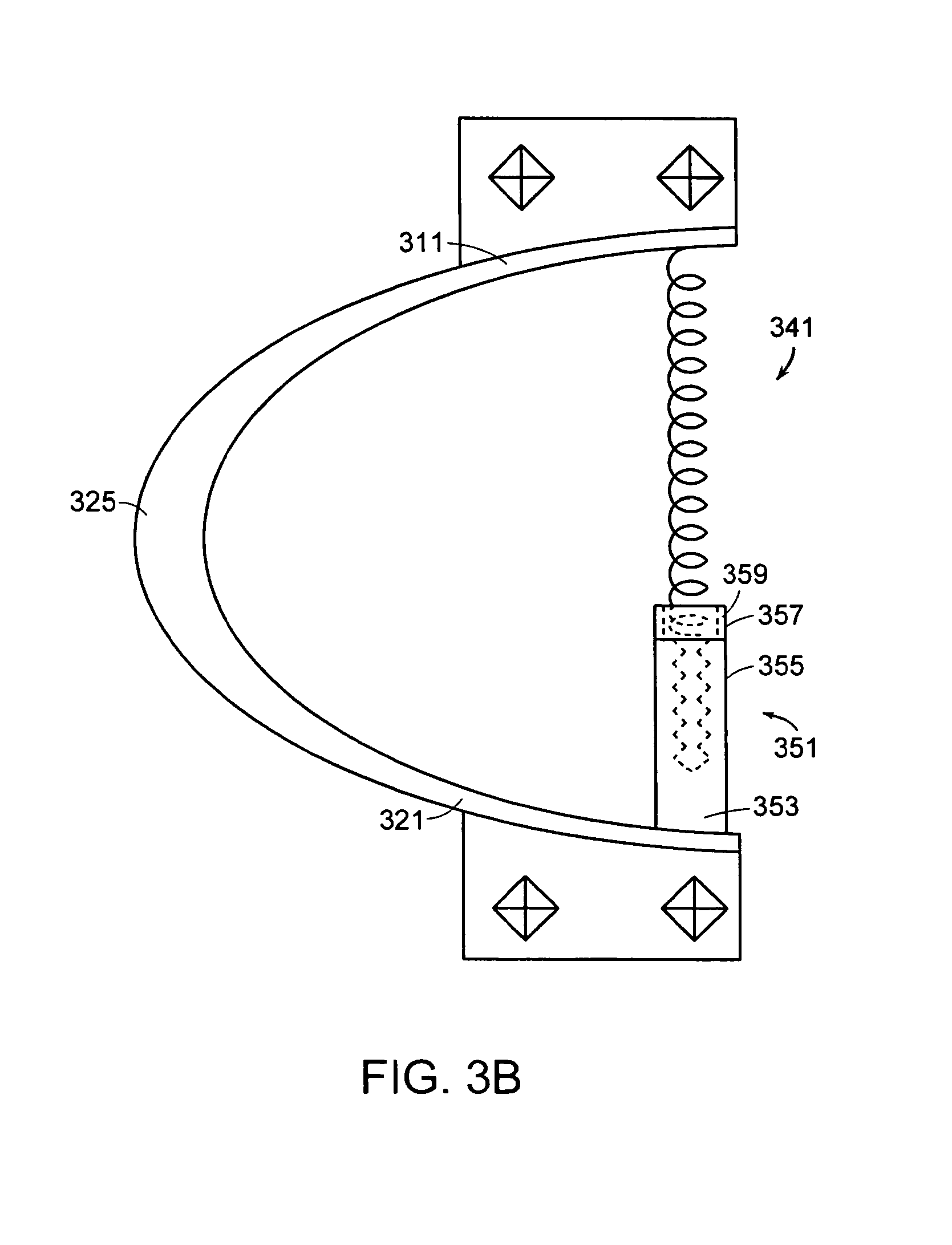
FIG. 3b is a side view of the third embodiment of the interspinous implant in the saggital plane.
FIGS. 4a-4c are perspective, longitudinal and frontal cross-sectional views of a fourth embodiment of the present invention.
FIG. 4d is a side view of the fourth embodiment of the interspinous implant implanted between adjacent vertebrae.
FIGS. 5a-b are side views of a fifth embodiment of the interspinous implant having outer and inner flexible shells.
FIG. 6 is a side view of a functional spinal unit of the human anatomy.
DETAILED DESCRIPTION OF THE FIGURES
For the purposes of the present invention, the term "interspinous" refers to the volume located between two adjacent spinous processes of adjacent vertebrae. The terms "anterior" and "posterior" are used as they are normally used in spinal anatomy. Accordingly, the "anterior" portion of the interspinous device is that portion rests relatively close to the spinal cord, while the "posterior" portion of the interspinous device is that portion rests relatively close to the skin on the patient's back. Now referring to FIG. 6, there is provided an anatomic "functional spinal unit" or FSU comprising an upper vertebrae Vu having an upper vertebral body VB.sub.U and an upper spinous process SPu, a lower vertebra having a lower vertebral body VB.sub.L having a lower spinous process SP.sub.L. The vertebral bodies lies in the anterior A portion of the FSU, while the spinous processes lie in the posterior portion P of the FSU. Disposed between the vertebral bodies is a disc space DISC. Disposed between the spinous process is an "interspinous region". Disposed between the spinous process and the vertebral body of each vertebra is a lamina L. The supraspinous ligament SSL lies posterior to the spinous processes. The Posterior longitudinal ligament PLL lies posterior to the vertebral bodies.
Now referring to FIGS. 1a and 1b, there is provided an interspinous implant 1 for insertion between adjacent spinous processes, the implant comprising:
a) a flexible body 11: i) an upper posterior portion 21 having an upper surface 23 adapted to bear upon an upper spinous process and a width W.sub.UP, ii) a lower posterior portion 31 having a lower surface 33 adapted to bear upon a lower spinous process and a width WL.sub.P, and iii) a flexible arcuate anterior wall 41 connecting the upper and lower portions and having a narrowed portion 43 defining a minimum width W.sub.DW, wherein the minimum width of the anterior wall is less than the width W.sub.UP of the upper portion.
Now referring to FIG. 1c, in use, the implant of FIGS. 1a and 1b is inserted into the interspinous region of an functional spinal unit (FSU), that is, between the adjacent spinous processes. The U-shaped body has a stiffness and geometry adapted to provide the desired spacing between the upper and lower process. In addition, in preferred embodiments, the U-shaped body is adapted to be somewhat flexible, so that it somewhat restricts the extent of extension motion of the FSU.
In preferred embodiments, the flexible body is U-shaped. In other embodiments, the flexible body has a posterior wall (preferably, arcuate) that flexibly connects the posterior portions of the upper and lower bearing surfaces of the flexible body to provide an overall substantially oval shape.
Preferably, the flexible body has a configuration and is made of a material that provides a first stiffness that limits the range of motion of the FSU. In some embodiments, the flexible body stiffness provides at least 50% of the overall initial stiffness of the implant, preferably at least 75%, more preferably at least 90%.
Preferably, the flexible body is adapted to provide a stiffness of between 50 N/mm and 1000 N/mm, more preferably between 100 N/mm and 500 N/mm. When the flexible body stiffness is in this range, it maintains the flexion/extension ROM of a normal lumbar FSU to less than 20 degrees, with less than 13 degrees of motion in flexion and less than 7 degrees of motion in extension. Preferably, the typical displacement of the posterior ends of the device under physiologic loading in the saggital plane is in the range of 1-6 mm.
The flexible can be made of a suitable biocompatible material typically used in structural spinal applications, including metals, plastics and ceramics. In some embodiments, the flexible body is made of a material selected from the group consisting of titanium alloy (including memory metals and superelastic alloys), stainless steel, and chrome cobalt. Preferably, the flexible body is provided in a sterile form.
Now referring to FIG. 1, in some embodiments, the flexible body has a height H of between 10 mm and 20 mm; a thickness T of between 1 mm and 2 mm; a length L of between 20 mm and 30 mm, and a width W of between 3 and 20 mm, preferably between 5 mm and 10 mm. In these embodiments, the implant can be easily inserted between typical adjacent spinous processes.
In some embodiments, the flexible body has a longitudinal cross section having a horseshoe shape. In others, the longitudinal cross-section describes a circle. In others, it is a pill shape. In others, it is substantially oval. In some embodiments, the upper and lower posterior portions are substantially non-parallel.
In some embodiments, as shown in FIG. 1b, the upper and lower posterior portions of the flexible body each have a longitudinal recess 25 defining a bearing surface 23, 33 and opposing recess walls 27. The recess shape is adapted to receive projecting portions of the opposed spinous processes, thereby securing the U-shaped shell between the spinous processes. In some embodiments, the recess walls have teeth 28 extending inwardly therefrom that provide a more grip upon the spinous processes. In some embodiments, at least the bearing surfaces of the recess have teeth 415 (as shown in FIG. 4c) extending outwardly therefrom that provide a more grip upon the spinous processes.
In some embodiments, the recess 25 defines an upper pair of extensions 45 extending from the bearing surface 33 and collectively defining a bracket. Each extension may comprise a transverse throughhole (not shown) adapted for fixing the implant to the adjacent spinous processes.
In some embodiments, each extension comprises a transverse throughhole adapted for fixing the implant to the adjacent spinous processes. In some embodiments, the implant further comprises a fastening element having a first end extending through the first transverse throughole and a second end extending through the second transverse through-hole.
The flexible body of the present invention preferably has a flexible anterior wall connecting the upper and lower portions of the U-shaped body, thereby providing a spring quality to the U-shaped body for flexibly resisting extreme FSU extension. This flexible anterior wall is preferably shaped to conform with the opposed surfaces of the opposing spinous processes (as shown in FIG. 1c). This quality also insures the grip of the implant and reduces unwanted stresses upon the flexible body. In some embodiments, the thickness of the distal wall is greater than the thickness of the posterior portions.
Now referring to FIGS. 2a and 2b, there is provided an interspinous implant 51 for insertion between adjacent spinous processes, the implant comprising:
a) a flexible U-shaped body 61:
i) an upper portion 71 having an upper surface 73 adapted to bear upon an upper spinous process and a lower surface 75, ii) a lower portion 81 having a lower surface 83 adapted to bear upon a lower spinous process and an upper surface 85, iii) a flexible distal wall 91 connecting the upper and lower portions, and b) a cushion element 95 having an upper surface 97 and a lower surface 99, wherein the lower surface of the upper portion of the flexible body comprises a porous coating 98 thereon, and wherein the upper surface of the cushion element is interdigitated with the porous coating.
In use, the cushion element provides a dampening effect upon natural extension. The interdigitated nature of the cushion bond reduces migration concerns.
In some embodiments, the bonding covers substantially the entire extent of the inner surface of the U-shaped body (i.e., the upper surface of the cushion is bonded to the lower surface of the upper posterior portion, the anterior surface of the cushion is bonded to the posterior surface of the flexible anterior wall, and the lower surface of the cushion is bonded to the upper surface of the lower posterior portion).
Now referring to FIG. 2c, in some embodiments, the bonding covers only the posterior portions of the inner surface of the U-shaped body (i.e., the lower surface of the upper posterior portion, and the upper surface of the lower posterior portion, but not the posterior surface of the flexible anterior wall). The partial coverage of this embodiment provides an amount of stress relief to the cushion-U-shaped body interface.
The cushion element of FIGS. 2a-2b is preferably made of an elastomeric material, more preferably a polyolefin rubber or carbon black reinforced polyolefin rubber. The hardness of the elastomeric cushion element is preferably between 56 and 72 shore A durometer. The ultimate tensile strength of the cushion element is preferably greater than 1600 psi. The cushion element preferably has an ultimate elongation greater than 300% using the ASTM D412-87 testing method, and a tear resistance greater than 100 psi using the ASTM D624-86 testing method. Although the cushion element is preferably a polyolefin rubber, it can be made of any elastomeric material that simulates the response of the natural ligaments.
Still referring to FIG. 2a, a porous coating 98 is provided as the inner surface of the U-shaped body. The porous coating provides an opportunity for the cushion element to interdigitate with the porous coating, and so obtain a greater amount of surface contact between the U-shaped body and the cushion, thereby achieving a lower maximum stress. In some embodiments, the coating covers the entire extent of the inner surface of the U-shaped body (i.e., the upper surface of the cushion is bonded to the lower surface of the upper posterior portion, the anterior surface of the cushion is bonded to the posterior surface of the flexible anterior wall, and the lower surface of the cushion is bonded to the upper surface of the lower posterior portion). Preferably, the coating comprises a layer of small spherical particles or beads.
In some embodiments, the coating covers only the posterior portions of the inner surface of the U-shaped body (i.e., the lower surface of the upper posterior portion, and the upper surface of the lower posterior portion, but not the posterior surface of the flexible anterior wall).
In some embodiments, a coating may also be applied to the superior side of the upper portion and the inferior side of the lower portion to promote bony ingrowth and osteointegration. In some embodiments thereof, and the coating may include beads, and may have osteobiologic components such as hydroxyapatite or tricalcium phosphate.
The present inventors have noted that there may be a need to correct the range of motion (ROM) provided by a motion disc after the motion disc has been implanted and there is need to change the load transferred through the facet joints to alleviate pain and facet joint degeneration.
For example, because implantation of spinal prostheses is an inexact procedure, there may be times when implantation provides too much or too little motion. For example, in some implantation procedures, damage to the anterior longitudinal ligament (ALL) is contemplated. Because the ALL in its physiologic form restricts the flexion/extension range of the natural disc, damage to it may provide the implanted disc with an unacceptably large range of motion (ROM) in flexion and extension. This overly large ROM is problematic because it produces atypical loads upon the facet joints as well as the adjacent intervertebral discs, thereby leading to premature degeneration of those facet joints and intervertebral discs. Accordingly, there may be a need to post-operatively correct the ROM of the implant in order to fine tune the ROM.
In another example, an implanted disc has an acceptable ROM at the time of implantation, but the patient undergoes typical aging so that the patient's normal range of motion decreases over time. In this case, it may be desirable to decrease the implant ROM so that it corresponds with the patient's natural decreased ROM.
Accordingly, there may be a need to post-operatively correct the ROM of the implant in order to adjust the implant ROM to the new needs of the patient.
The implant of the present invention is advantageous because it can be inserted into the spine at a first stiffness, and then adjusted to a second stiffness to meet the needs of the particular patient.
In a first preferred embodiment, the stiffness of the implant is adjusted post-operatively in order to fine tune the implant to the surgical needs of the patient.
In a second preferred embodiment, the stiffness of the implant is adjusted in order to fine tune the implant to the changing post-surgical needs of the patient.
In many embodiments, the stiffness of the implant is increased in order to reduce the ROM of a functional spinal unit (FSU).
In some embodiments, the implant further comprises a compression spring, and the overall stiffness of the implant is changed by adjusting the length of the compression spring. Now referring to FIGS. 3a-3b, in some embodiments, there is provided an interspinous implant 301 for insertion between adjacent spinous processes, the implant comprising: a) a flexible outer shell 311 comprising: i) an upper posterior portion 315 adapted to bear upon an upper spinous process, ii) a lower posterior portion 321 adapted to bear upon a lower spinous process, iii) a flexible anterior wall 325 connecting the upper and lower posterior portions, b) a compression spring 341 having an upper portion 343 and a lower portion 345, the upper portion of the compression screw being attached to the upper posterior portion of the flexible outer shell, and c) a worm screw 351 having a lower portion 353 connected to the lower posterior portion and an upper portion 355 contacting the lower portion of the compression spring. In this particular embodiment, the upper portion of the worm screw comprises a cup 357 having an annular sidewall 359 extending upward. The lower end portion of the compression spring is not rigidly attached to the cup, but rather sits freely in the annulus and bears against the cup. Containment by the cup allows the upper end of the worm screw to simply bear against the lower end of the spring without requiring rigid connection thereto.
In use, actuation of the worm screw causes inner thread 363 of the worm screw to turn relative to the outer cylinder 361 of the worm screw. The outer cylinder 361 responds by moving axially upward, thereby forcing compression of the compression spring, and increasing the effective resistance of the device to axial compression.
Now referring to FIGS. 4a-4c, in some embodiments, there is provided an interspinous implant 401 for insertion between adjacent spinous processes, the implant having an implant stiffness and comprising:
a) a flexible outer shell 411 having a shell stiffness and comprising:
i) an upper surface 415 adapted to bear upon an upper spinous process, ii) a lower surface 421 adapted to bear upon a lower spinous process, iii) an arcuate anterior wall 425 connecting the upper and lower surfaces, and iv) an arcuate posterior wall 431 extending between the upper and lower surfaces, b) compliant side walls 451,453, extending between the upper and lower surfaces, and c) an inner core 441 (such as a hydrogel) contained within the shell, wherein the inner core has an adjustable stiffness.
When it is desired to decrease the range of motion ("ROM") of the functional spinal unit ("FSU"), the stiffness of the core material may be increased, thereby increasing the stiffness of the implant and its resistance to an axial load. The resulting increase in the stiffness of the interspinous implant provides a more substantial resistance to extension, thereby desirably decreasing the ROM of the FSU to correspond with the needs of the patient.
Similarly, when it is desired to increase the range of motion ("ROM") of the functional spinal unit ("FSU"), the stiffness of the core material is decreased, thereby decreasing the stiffness of the implant and its resistance to an axial load. The resulting decrease in the stiffness of the interspinous implant reduces resistance to extension, thereby desirably increasing the ROM of the FSU to correspond with the needs of the patient.
The implant of this embodiment of the present invention also has a flexible posterior wall extending between the upper and lower portions of the U-shaped body. This posterior wall is preferably arcuate and preferably connects the upper surface of the lower portion and the lower surface of the upper portion of the U-shaped body to form a substantially oval body (as shown). In this condition, the posterior wall provides substantial closure to the U-shaped body. Accordingly, adjustment of the stiffness of the core material residing within the outer shell increases or decreases the stiffness of the implant.
The compliance of the sidewalls is selected to correspond with the level of resistance desired by the implant. For example, in some embodiments (as in FIG. 4a-4c) the sidewalls are very thin and may be made of a very flexible material, such as a plastic weave. In these embodiments, the high compliance of the sidewalls will allow the core material to bulge laterally in response to an axial load, thereby tempering the resistance provided by the core material to the axial load.
In other embodiments, however, the sidewalls can be made of metal, and even be integral with the outer shell. In these embodiments, the sidewalls will be flexible but more rigid than a plastic membrane. In these embodiments, the relative rigidity of the sidewalls will not allow the core material to bulge significantly laterally, thereby augmenting the resistance provided by the core material to the axial load.
Preferably, the core is a fluid material contained within the cavity of the shell and is made of a material having a quality whose adjustment will produce a change in the stiffness of the implant. When the stiffness of the core is adjusted, the overall stiffness of the implant correspondingly changes. In some embodiments, the core has a first stiffness and contributes between 10 and 20% of the overall initial stiffness of the implant. In such embodiments, the stiffness of the core is increased to a second stiffness that increases the overall initial stiffness of the implant up to at least 40% to provide an adjusted implant stiffness of at least 300 N/mm, and more preferably at least 500 N/mm. When the implant stiffness is in this range, the implant can by itself provide sufficient stiffness to reduce the extension of a normal lumbar FSU to less than 7 degrees, preferably less than 5 degrees.
Preferably, the core material is selected to be sensitive to an external stimulus, which, when applied, stimulates the core material to adjust its stiffness from a first stiffness to a second stiffness. In some embodiments, the stimulus stimulates the core to increase its stiffness. In some embodiments, the stimulus stimulates the core to lower its stiffness.
Preferably, the core material is sensitive to a stimulus selected from the group consisting pH, light, and electric current.
In preferred embodiments, the core material comprises a hydrogel. In preferred embodiments, the hydrogel undergoes expansion when stimulated by a decreased pH. The resulting expansion of the core material increases the stiffness of the core, thereby increasing the stiffness of the implant and providing increased resistance to extension by the FSU. In some embodiments, the hydrogel is selected from ionic polymers disclosed in US Published Patent Application No. 2002/0039620, the specification of which is incorporated by reference in its entirety. In some embodiments, the hydrogel is selected from ionic polymers disclosed in U.S. Pat. No. 6,475,639, the specification of which is incorporated by reference in its entirety.
When pH is selected as the stimuli, in some embodiments, an acid or a base is introduced into the core material from an ex vivo source. For example, the acid or base can be administered subcutaneously via a hypodermic needle and introduced into the core material through a fluid port 455. The provision of a fluid port provides the surgeon with the flexibility to selected the amount of acid or base needed to suit the needs of the patient.
In other embodiments in which pH is selected as the stimuli, the implant further comprises a container that individually houses and sequesters the acid or base from the core material. For example, the acid or base can be sequestered in a valved, separate compartment within the shell that is in fluid connection with the cavity housing the core material. The valve is opened (for example, by telemetry), the acid or base enters the cavity housing the core material and mixes with the core material. The resulting pH change causes a change in the specific volume of the core material, thereby increasing or decreasing the stiffness of the core material and the overall implant. The advantage of this embodiment is that the stiffness of the implant is changed through a completely non-invasive technique.
In some embodiments (not shown), the device could be made of a shape memory metal having a relatively flexible property during the martensitic phase and a relatively stiff property in the austenitic phase. In one embodiment, this memory metal device could be implanted in its flexible martensitic phase. If the clinician desires to increase the stiffness of the implant, the clinician could raise the temperature of the device (by heating) to a temperature above its austenitic phase, thereby increasing the stiffness of the device and increasing its resistance to an axial compressive load.
In some embodiments of the present invention, the implant further comprises smart features for helping the surgeon monitor and react to the changing conditions of the implanted device.
In some embodiments, a sensing means is also used with the implant of the present invention. This sensing means analyzes physical surroundings. Its purpose is to identify when a significant change has occurred which could warrant adjusting the stiffness of the implant. The sensor can be contained within the implant, or provided as a stand alone entity.
In some embodiments, a reporting means for reporting the findings of the sensors to an ex vivo source is also used with the implant of the present invention. The reporter can be contained within the implant, or provided as a stand alone entity.
In some embodiments, a receiver for receiving ex vivo-generated information is also used with the implant of the present invention. The receiver can be contained within the implant, or provided as a stand alone entity.
In some embodiments, the implant comprises two shells having flexible anterior walls extending in the same direction, wherein the stiffness is adjusted by adjusting the distance between the respective flexible anterior walls. Now referring to FIG. 5a, there is provided an interspinous implant 501 for insertion between adjacent spinous processes, the implant comprising:
a) a flexible outer shell 511 comprising: i) an upper posterior portion 515 adapted to bear upon an upper spinous process and having a lower end 517 having a first set of teeth 519, ii) a lower posterior portion 521 adapted to bear upon a lower spinous process and having a upper end 522 having a second set of teeth 523, iii) a flexible anterior wall 525 connecting the upper and lower posterior portions of the flexible outer shell,
b) a flexible inner shell 551 comprising: i) an upper posterior portion 555 having an upper end 556 having a third set of teeth 557 engaged in the first set of teeth, ii) a lower posterior portion 571 having a lower end 573 having fourth set of teeth 577 engaged in the second set of teeth, iii) a flexible anterior wall 575 connecting the upper and lower posterior portions.
In use, the implant of FIG. 5a is implanted into the interspinous void so that the opposing sets of teeth of the inner and outer shells are engaged to the opposed spinous processes, thereby providing a secure implant and defining a distance between the anterior walls D.sub.1 of the inner and outer shells. If the clinician desires to change the stiffness of the implant, then the clinician may alter the distance D between the anterior walls of the inner and outer shells. Reducing the distance D between the anterior walls will cause a decrease in the stiffness of the implant, while increasing the distance D between the anterior walls will cause an increase in the stiffness of the implant.
Now referring to FIG. 5b, when the clinician desires to decrease the stiffness of the implant of FIG. 5a, the clinician can use a pair of foreceps (not shown) to engage the slots 581 provided on the upper and lower posterior portions of the inner shell. Providing a clamping force through the foreceps squeezes together the posterior portions of the inner shell, thereby disengaging the respective pairs of teeth. The clinician can then move the disengaged inner shell anteriorly by a predetermined distance to a second position (shown in shadow), thereby decreasing the distance between the anterior walls to a smaller distance D.sub.2 and lowering the stiffness of the implant.
In other embodiments, the slots of the implant of FIGS. 5a and 5b are replaced within other means for adjusting the distance D between the flexible anterior walls of the inner and outer shells. For example, in some embodiments, a set screw or a worm gear may be provided on the implant to alter the distance D, thereby adjusting the stiffness of the implant.
Therefore, in accordance with the present invention, there is provided an interspinous implant for insertion between adjacent spinous processes, the implant comprising:
a) a flexible outer shell comprising: i) an upper posterior portion adapted to bear upon an upper spinous process and having a lower end having a first set of teeth, ii) a lower posterior portion adapted to bear upon a lower spinous process and having a upper end having a second set of teeth, iii) a flexible anterior wall connecting the upper and lower posterior portions of the flexible outer shell,
b) a flexible inner shell comprising: i) an upper posterior portion having an upper end having a third set of teeth engaged in the first set of teeth, ii) a lower posterior portion having a lower end having fourth set of teeth engaged in the second set of teeth, iii) a flexible anterior wall connecting the upper and lower posterior portions.
In preferred embodiments, the implant of the present invention is used posteriorly in conjunction with a motion disc inserted within the disc space of the anterior portion of the spinal column. For example, in some embodiments, the implant of the present invention is used in conjunction with a motion disc having a large range of motion ("ROM"). Various motion discs are described by Stefee et al. in U.S. Pat. No. 5,071,437; Gill et al. in U.S. Pat. No. 6,113,637; Bryan et al. in U.S. Pat. No. 6,001,130; Hedman et al. in U.S. Pat. No. 4,759,769; Ray in U.S. Pat. No. 5,527,312; Ray et al. in U.S. Pat. No. 5,824,093; Buttner-Janz in U.S. Pat. No. 5,401,269; and Serhan et al. in U.S. Pat. No. 5,824,094; all which documents are hereby incorporated herein by reference in their entireties. The flexibility of the flexible body provides resistance to extreme extension, thereby restricting the motion disc to a more narrow and more physiologically desirable range of motion.
Therefore, in accordance with the present invention, there is provided a kit for providing therapy to a functional spinal unit comprising an upper vertebrae having an upper spinous process, a lower vertebrae having a lower spinous process, and a disc space therebetween, the kit comprising:
a) an interspinous implant for insertion between adjacent spinous processes, the implant comprising a flexible (preferably, U-shaped) body comprising:
i) an upper posterior portion having an upper surface adapted to bear upon an upper spinous process, ii) a lower posterior portion having a lower surface adapted to bear upon a lower spinous process, and iii) a flexible (preferably arcuate) anterior wall connecting the upper and lower portions, and b) an artificial disc adapted for insertion into the disc space.
* * * * *
References
D00000
D00001
D00002
D00003
D00004
D00005
D00006
D00007
D00008
D00009
XML
uspto.report is an independent third-party trademark research tool that is not affiliated, endorsed, or sponsored by the United States Patent and Trademark Office (USPTO) or any other governmental organization. The information provided by uspto.report is based on publicly available data at the time of writing and is intended for informational purposes only.
While we strive to provide accurate and up-to-date information, we do not guarantee the accuracy, completeness, reliability, or suitability of the information displayed on this site. The use of this site is at your own risk. Any reliance you place on such information is therefore strictly at your own risk.
All official trademark data, including owner information, should be verified by visiting the official USPTO website at www.uspto.gov. This site is not intended to replace professional legal advice and should not be used as a substitute for consulting with a legal professional who is knowledgeable about trademark law.