Methods and devices for forming a tissue fold
Harshman O
U.S. patent number 10,433,838 [Application Number 14/558,496] was granted by the patent office on 2019-10-08 for methods and devices for forming a tissue fold. This patent grant is currently assigned to ENDOGASTRIC SOLUTIONS, INC.. The grantee listed for this patent is ENDOGASTRIC SOLUTIONS, INC.. Invention is credited to Scott Harshman.
| United States Patent | 10,433,838 |
| Harshman | October 8, 2019 |
Methods and devices for forming a tissue fold
Abstract
A device for forming a tissue fold includes a recess and an opening at the end of the recess. Tissue is drawn into the recess and through the opening using a tissue engaging element. As the tissue is drawn through the opening, the tissue layers are compressed together. A fastener is used to secure the tissue fold.
| Inventors: | Harshman; Scott (Kirkland, WA) | ||||||||||
|---|---|---|---|---|---|---|---|---|---|---|---|
| Applicant: |
|
||||||||||
| Assignee: | ENDOGASTRIC SOLUTIONS, INC.
(Redmond, WA) |
||||||||||
| Family ID: | 42738293 | ||||||||||
| Appl. No.: | 14/558,496 | ||||||||||
| Filed: | December 2, 2014 |
Prior Publication Data
| Document Identifier | Publication Date | |
|---|---|---|
| US 20150112365 A1 | Apr 23, 2015 | |
Related U.S. Patent Documents
| Application Number | Filing Date | Patent Number | Issue Date | ||
|---|---|---|---|---|---|
| 12383109 | Mar 18, 2009 | 8906037 | |||
| Current U.S. Class: | 1/1 |
| Current CPC Class: | A61B 17/064 (20130101); A61B 17/0401 (20130101); A61B 17/072 (20130101); A61B 17/068 (20130101); A61B 17/00234 (20130101); A61B 2017/0464 (20130101); A61B 2017/0496 (20130101); A61B 2017/00349 (20130101); A61B 2017/00827 (20130101); A61B 2017/0419 (20130101); A61B 2017/0409 (20130101); A61B 2017/081 (20130101); A61B 2017/0649 (20130101); A61B 2017/07214 (20130101); A61B 2017/00818 (20130101) |
| Current International Class: | A61B 17/072 (20060101); A61B 17/064 (20060101); A61B 17/04 (20060101); A61B 17/00 (20060101); A61B 17/068 (20060101); A61B 17/08 (20060101) |
| Field of Search: | ;606/139,142,143 |
References Cited [Referenced By]
U.S. Patent Documents
| 2753870 | July 1956 | Muffly |
| 3875928 | April 1975 | Angelchik |
| 4006747 | February 1977 | Kronenthal |
| 4271828 | June 1981 | Angelchik |
| 4576772 | March 1986 | Carpenter et al. |
| 4595007 | June 1986 | Mericle |
| 4669473 | June 1987 | Richards et al. |
| 4696300 | September 1987 | Anderson |
| 4846836 | July 1989 | Reich |
| 4895148 | January 1990 | Bays et al. |
| 4921479 | May 1990 | Grayzel |
| 5006106 | April 1991 | Angelchik et al. |
| 5041129 | August 1991 | Hayhurst et al. |
| 5080543 | January 1992 | Murphy |
| 5088979 | February 1992 | Filipi et al. |
| 5254126 | October 1993 | Filipi et al. |
| 5314473 | May 1994 | Godin |
| 5403326 | April 1995 | Harrison et al. |
| 5411508 | May 1995 | Bessler et al. |
| 5411520 | May 1995 | Nash et al. |
| 5549621 | August 1996 | Bessler et al. |
| 5571074 | November 1996 | Buckman et al. |
| 5571116 | November 1996 | Bolanos et al. |
| 5626614 | May 1997 | Hart |
| 5676674 | October 1997 | Bolanos et al. |
| 5713903 | February 1998 | Sander et al. |
| 5759151 | June 1998 | Sturges |
| 5810882 | September 1998 | Bolduc et al. |
| 5814054 | September 1998 | Kortenbach et al. |
| 5861036 | January 1999 | Godin |
| 5879372 | March 1999 | Bartlett et al. |
| 5887594 | March 1999 | LoCicero |
| 5897562 | April 1999 | Bolanos et al. |
| 5938668 | August 1999 | Scirica et al. |
| 6086600 | July 2000 | Kortenbach |
| 6098629 | August 2000 | Johnson et al. |
| 6113609 | September 2000 | Adams |
| 6113611 | September 2000 | Allen et al. |
| 6142957 | November 2000 | Diamond et al. |
| 6254642 | July 2001 | Taylor |
| 6264700 | July 2001 | Kilcoyne et al. |
| 6302311 | October 2001 | Adams et al. |
| 6302917 | October 2001 | Dua et al. |
| 6312437 | November 2001 | Kortenbach |
| 6315789 | November 2001 | Cragg |
| 6419669 | July 2002 | Frazier et al. |
| 6428548 | August 2002 | Durgin et al. |
| 6447524 | September 2002 | Knodel et al. |
| 6743239 | June 2004 | Kuehn et al. |
| 6773440 | August 2004 | Gannoe et al. |
| 6773441 | August 2004 | Laufer et al. |
| 6790214 | September 2004 | Kraemer |
| 6835200 | December 2004 | Laufer et al. |
| 6916332 | July 2005 | Adams |
| 6921361 | July 2005 | Suzuki et al. |
| 7022118 | April 2006 | Ariura et al. |
| 7037344 | May 2006 | Kagan et al. |
| 7074229 | July 2006 | Adams et al. |
| 7083630 | August 2006 | DeVries et al. |
| 7220266 | May 2007 | Gambale |
| 7347863 | March 2008 | Rothe et al. |
| 7618426 | November 2009 | Ewers et al. |
| 7632287 | December 2009 | Baker et al. |
| 7678123 | March 2010 | Chanduszko |
| 7713277 | May 2010 | Laufer et al. |
| 7776057 | August 2010 | Laufer et al. |
| 7811295 | October 2010 | Kortenbach |
| 7850704 | December 2010 | Burnett et al. |
| 7857184 | December 2010 | Viola |
| 7857823 | December 2010 | Laufer et al. |
| 7860555 | December 2010 | Saadat |
| 7866526 | January 2011 | Green et al. |
| 7918787 | April 2011 | Saadat |
| 7942887 | May 2011 | Kraemer et al. |
| 7951157 | May 2011 | Gambale |
| 7954687 | June 2011 | Zemlok et al. |
| 7955340 | June 2011 | Michlitsch et al. |
| 8057494 | November 2011 | Laufer et al. |
| 8252009 | August 2012 | Weller et al. |
| 8277468 | October 2012 | Laufer et al. |
| 8308765 | November 2012 | Saadat et al. |
| 8343175 | January 2013 | Ewers et al. |
| 8574243 | November 2013 | Saadat et al. |
| 2002/0022853 | February 2002 | Swanson et al. |
| 2002/0035370 | March 2002 | Kortenbach |
| 2002/0040226 | April 2002 | Laufer et al. |
| 2002/0055772 | May 2002 | McGuckin, Jr. et al. |
| 2002/0072761 | June 2002 | Abrams et al. |
| 2002/0078967 | June 2002 | Sixto, Jr. et al. |
| 2002/0082621 | June 2002 | Schurr et al. |
| 2002/0143349 | October 2002 | Gifford, III et al. |
| 2002/0183765 | December 2002 | Adams |
| 2002/0198541 | December 2002 | Smith et al. |
| 2003/0023230 | January 2003 | Lewis et al. |
| 2003/0055442 | March 2003 | Laufer |
| 2003/0065340 | April 2003 | Geitz |
| 2003/0065359 | April 2003 | Weller et al. |
| 2003/0093117 | May 2003 | Saadat |
| 2003/0120289 | June 2003 | McGuckin, Jr. |
| 2003/0120292 | June 2003 | Park et al. |
| 2003/0171760 | September 2003 | Gambale |
| 2003/0187465 | October 2003 | Bailly et al. |
| 2003/0191497 | October 2003 | Cope |
| 2003/0216613 | November 2003 | Suzuki et al. |
| 2003/0216754 | November 2003 | Kraemer et al. |
| 2003/0220657 | November 2003 | Adams |
| 2004/0044304 | March 2004 | Hill et al. |
| 2004/0044364 | March 2004 | DeVries et al. |
| 2004/0087976 | May 2004 | DeVries et al. |
| 2004/0093024 | May 2004 | Lousararian et al. |
| 2004/0116949 | June 2004 | Ewers et al. |
| 2004/0133236 | July 2004 | Chanduszko |
| 2004/0138529 | July 2004 | Wiltshire et al. |
| 2004/0147958 | July 2004 | Lam et al. |
| 2004/0148034 | July 2004 | Kagan et al. |
| 2004/0153102 | August 2004 | Therin et al. |
| 2004/0153103 | August 2004 | Schwartz et al. |
| 2004/0162568 | August 2004 | Saadat et al. |
| 2004/0215216 | October 2004 | Gannoe et al. |
| 2004/0236357 | November 2004 | Kraemer et al. |
| 2004/0243223 | December 2004 | Kraemer et al. |
| 2005/0004575 | January 2005 | Sgro et al. |
| 2005/0017781 | January 2005 | Honda |
| 2005/0043759 | February 2005 | Chanduszko |
| 2005/0075653 | April 2005 | Saadat et al. |
| 2005/0085829 | April 2005 | Kraemer |
| 2005/0154405 | July 2005 | Kraemer et al. |
| 2005/0177176 | August 2005 | Gerbi et al. |
| 2005/0187565 | August 2005 | Baker et al. |
| 2005/0203547 | September 2005 | Weller et al. |
| 2005/0216040 | September 2005 | Gertner et al. |
| 2005/0228413 | October 2005 | Binmoeller et al. |
| 2005/0247320 | November 2005 | Stack et al. |
| 2005/0251162 | November 2005 | Rothe |
| 2005/0251176 | November 2005 | Swanstrom et al. |
| 2006/0009789 | January 2006 | Gambale |
| 2006/0135971 | June 2006 | Swanstrom |
| 2006/0190018 | August 2006 | Baker et al. |
| 2006/0253130 | November 2006 | Wolniewicz |
| 2006/0253142 | November 2006 | Bjerken |
| 2007/0021756 | January 2007 | Kortenbach |
| 2007/0021760 | January 2007 | Kelleher |
| 2007/0112363 | May 2007 | Adams |
| 2007/0129738 | June 2007 | Kraemer et al. |
| 2007/0191870 | August 2007 | Baker et al. |
| 2007/0191871 | August 2007 | Baker et al. |
| 2007/0219566 | September 2007 | Gambale |
| 2007/0276409 | November 2007 | Ortiz et al. |
| 2008/0015618 | January 2008 | Sonnenschein et al. |
| 2008/0287966 | November 2008 | Kraemer et al. |
| 2008/0294179 | November 2008 | Balbierz |
| 2009/0177214 | July 2009 | Adams |
| 2009/0198254 | August 2009 | Laufer et al. |
| 2009/0236388 | September 2009 | Cole et al. |
| 2010/0241139 | September 2010 | Harshman |
| 2011/0196391 | August 2011 | Forsell |
| 2011/0213390 | September 2011 | Kraemer et al. |
| 252607 | Sep 1992 | EP | |||
| 1999022649 | May 1999 | WO | |||
| 1999060931 | Dec 1999 | WO | |||
| 2000053102 | Sep 2000 | WO | |||
| 2000078227 | Dec 2000 | WO | |||
| 2001032084 | May 2001 | WO | |||
| 2001035834 | May 2001 | WO | |||
| 2001064964 | Sep 2001 | WO | |||
| 2001067964 | Sep 2001 | WO | |||
| 2001085034 | Nov 2001 | WO | |||
| 2001089391 | Nov 2001 | WO | |||
| 2002024058 | Mar 2002 | WO | |||
| 2002024080 | Mar 2002 | WO | |||
| 2002028289 | Apr 2002 | WO | |||
| 2002082621 | Oct 2002 | WO | |||
| 2002096327 | Dec 2002 | WO | |||
| 2003061480 | Jul 2003 | WO | |||
| 2003099140 | Dec 2003 | WO | |||
| 2004019787 | Mar 2004 | WO | |||
| 2004019788 | Mar 2004 | WO | |||
| 2004049982 | Jun 2004 | WO | |||
| 2004069055 | Aug 2004 | WO | |||
| 2005065412 | Jul 2005 | WO | |||
| 2005081817 | Sep 2005 | WO | |||
| 2006023764 | Mar 2006 | WO | |||
| 2006034484 | Mar 2006 | WO | |||
| 2006081368 | Aug 2006 | WO | |||
| 2007002817 | Jan 2007 | WO | |||
| 2007064713 | Jun 2007 | WO | |||
| 2010087756 | Aug 2010 | WO | |||
Other References
|
The gastroesophageal flap valve: in vitro and in vivo observations; Lucius D. Hill et al.; Gastrointestinal Endoscopy; vol. 44, No. 5, 1996; pp. 541-547; abstract. cited by applicant . Reappraisal of the flap valve mechanism in the gastroesophageal junction: A study of a new valvuloplasty procedure in cadavers; KjellB.A. Thor et al.; Acta Chir Scand 153:25-28, 1987; abstract. cited by applicant . The Plicator Procedure; 1 page; abstract. cited by applicant . Chuttani, MD. et al., "A novel endoscopic full-thickness plicator for treatment of GERD: an animal model study". Gastrointestinal Endoscopy, vol. 56, No. 1, 2002, pp. 116-122; abstract. cited by applicant . Jobe, et al., "Endoscopic Appraisal of the Gastroesophageal Valve After Antireflux Surgery", American Journal of Gastroenterology, ISSN 0002-9270; abstract. cited by applicant . International Search Report for PCT/US2012/054328. cited by applicant. |
Primary Examiner: Dornbusch; Dianne
Attorney, Agent or Firm: Fulwider Patton LLP
Parent Case Text
This application is a division of U.S. Ser. No. 12/383,109 filed Mar. 18, 2009, now U.S. Pat. No. 8,906,037, the entire contents of which are incorporated herein by reference.
Claims
What is claimed is:
1. A device for forming a tissue fold, comprising: a stationary mold having a fixed volume recess and an opening leading to the recess; an elongated slot having a distal end and a proximal end, the proximal end of the elongated slot being adjacent to a distal end of the recess; a cable having a helical coil at a distal end of the cable and being housed within the recess and configured to engage tissue, the helical coil being movable outside the fixed volume recess by extending through the elongated slot located distally of the opening leading to the fixed volume recess to engage tissue and to draw tissue through the opening and into the fixed volume recess; a centering mechanism disposed in the slot and looped around the cable to move the cable to a position substantially perpendicular to a longitudinal axis of the stationary mold; and wherein the opening is sized so that tissue drawn through the opening by the helical coil is compressed as the tissue fold enters the tissue mold.
2. The device of claim 1, further comprising: a fastener positioned to fasten together a tissue fold contained within the fixed volume recess.
3. The device of claim 1, wherein the opening is at a distal end of the fixed volume recess; and the helical coil is configured to draw the tissue proximally into the tissue mold.
4. The device of claim 1, wherein: the mold has two lateral openings, which communicate with the fixed volume recess and with the opening.
5. The device of claim 4, wherein: the lateral openings have a substantially uniform width.
6. The device of claim 4, wherein the lateral openings are L-shaped.
7. The device of claim 1, wherein: the cable and helical coil traverse a curved path within the tissue mold.
8. The device of claim 1, wherein: the cable and helical coil change in angular orientation with respect to a longitudinal axis of the tissue mold by at least 45 degrees when the cable and helical coil are moved through the mold.
9. The device of claim 1, wherein the centering mechanism is a wire loop wrapped around the cable.
10. The device of claim 9, wherein the cable freely slides through the wire loop, but the helical coil is larger than the wire loop and will not pass therethrough.
Description
BACKGROUND
The present invention is directed to methods and devices for approximating tissue and forming a tissue fold.
SUMMARY
The present invention provides a device for forming a tissue fold, which has a mold and a tissue engaging element. The mold has a recess and an opening leading to the recess. Tissue is drawn through the opening and into the mold using the tissue engaging element.
As tissue is drawn into the opening, the tissue forms a fold, which is compressed by the opening. In this manner, the entire fold is drawn through the opening and squeezed and compressed by the opening. The tissue layers are then fastened together to maintain tissue fold.
The opening is positioned at a distal end of the recess so that tissue is drawn proximally through the opening and into the tissue mold. The mold may also have two lateral openings, which communicate with the recess and with the opening at the distal end of the recess. The lateral edges of the tissue fold extend through the lateral openings as the tissue is drawn into the recess.
The tissue engaging element takes a curved path through the tissue mold and changes an angular orientation with respect to the mold by at least 45 degrees when passing through the mold.
The volume of the area around the device, such as the stomach, may also be reduced while drawing the tissue into the recess.
These and other aspects of the present invention will become apparent from the following description of the preferred embodiment.
DESCRIPTION OF DRAWINGS
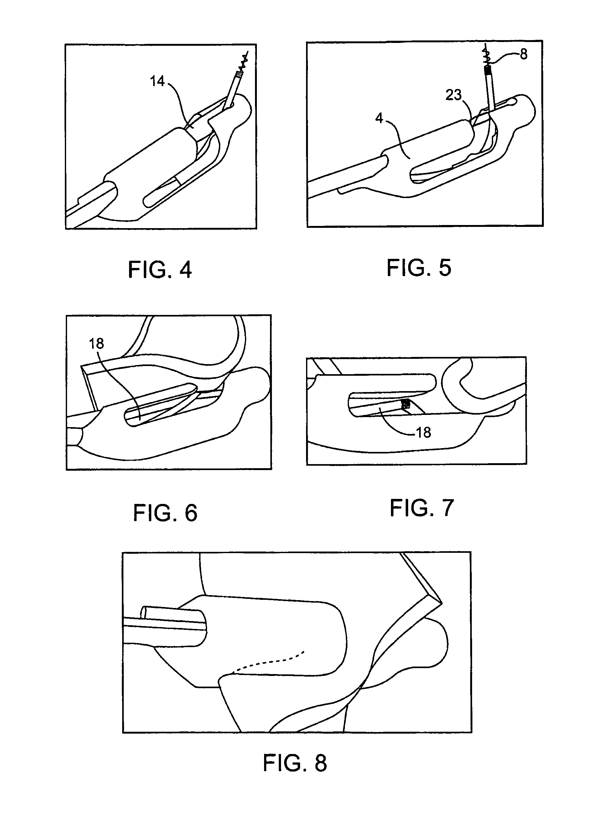
FIG. 1 shows a device for forming a tissue fold.
FIG. 2 shows a cross-sectional view of the device.
FIG. 3 shows a distal end of the device.
FIG. 4 shows a tissue engaging element extending from a mold.
FIG. 5 shows the tissue engaging element positioned to engage tissue.
FIG. 6 shows the tissue engaging element engaged with tissue and the tissue drawn toward the mold.
FIG. 7 shows the tissue fold just before entering the mold.
FIG. 8 shows the tissue drawn into the recess and a fastener applied to maintain the tissue fold.
DESCRIPTION OF THE PREFERRED EMBODIMENTS
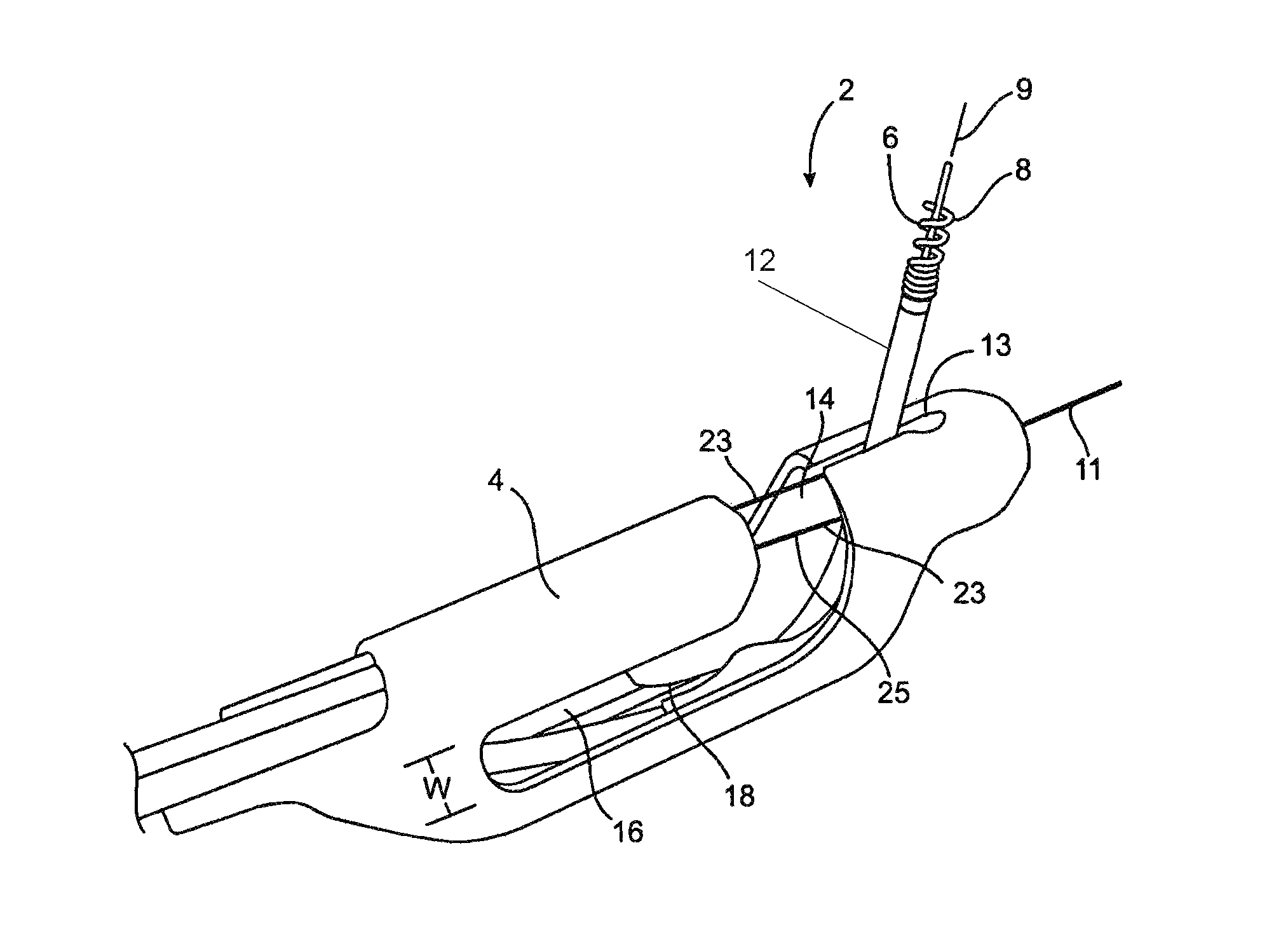
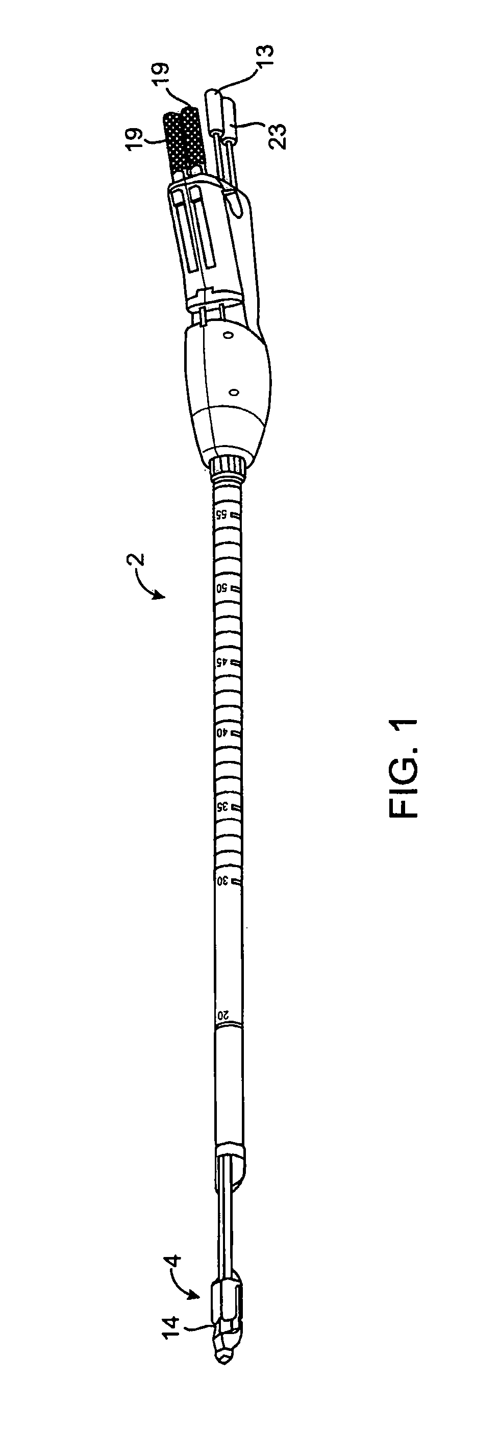
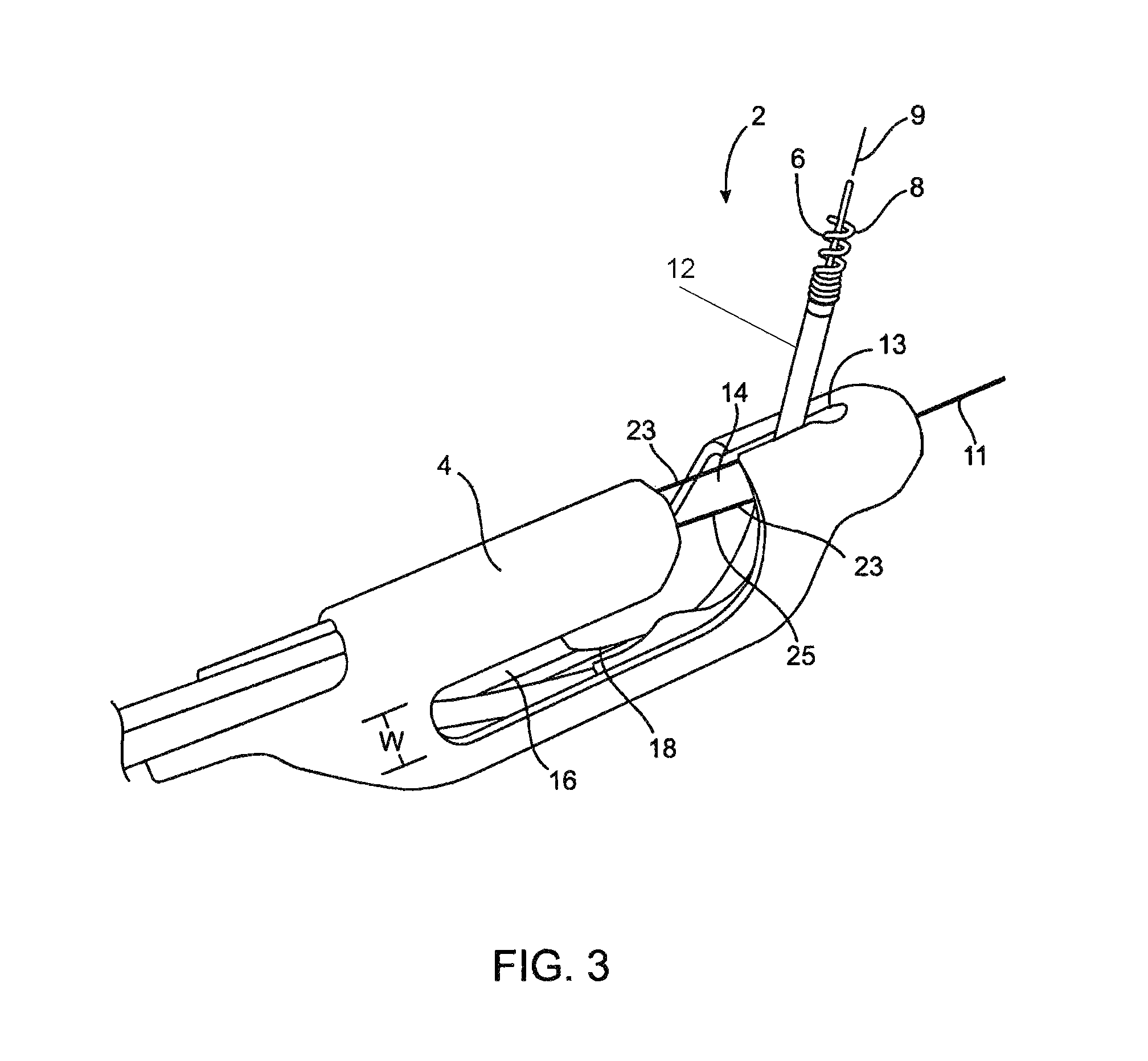
Referring to FIGS. 1-3, a device 2 for forming a tissue fold is shown. The device 2 has a tissue mold 4 and a tissue engaging element 6 which draws tissue into the mold 4.
The tissue engaging element 6 has a helical coil 8 with a sharp tip 10 which is rotated into engagement with tissue. The device 2 may include any other suitable mechanism for engaging tissue such as a hook, barb, or suction element. The tissue engaging element 6 is coupled to a cable 12 which may be rotated and translated in the manner described below to manipulate the element 6. The tissue engaging element 6 extends though a slot 13 in the body which stabilizes the element 6 and permit's the user to steer the element 6 with the mold 4. The coil 8 is initially directed somewhat laterally from the mold 4 as shown in FIG. 5. As the coil 8 moves into the mold 4, the coil 8 takes a curved path through the mold 4 so that a longitudinal axis 9 of the coil 8 changes angular orientation with respect to a longitudinal axis 11 of the mold by at least 45 degrees. A manipulator 13 extends from the proximal end of the device 2 and is used to move and rotate the coil 8. A lock (not shown) is used to lock rotation of the manipulator 13 (and coil 8) as described below in connection with the method of using the device 2.
The tissue mold 4 has an opening 14 which is relatively small so that the tissue fold is compressed and squeezed as the tissue enters the tissue mold 4. An advantage of the present invention is that squeezing the tissue in this manner may help to separate the tissue creating the fold from surrounding tissue. Such connections or adhesions to other tissue may not be desirable. An advantage of the present invention is that squeezing and compressing the tissue fold during introduction into the mold may help to reduce such connections and adhesions.
The tissue mold 4 has a recess 16 which receives the tissue fold. The recess 16, as shown in FIG. 3, is defined by a fixed volume, i.e., the recess 16 does not expand or contract when receiving tissue. Two lateral openings 18 communicate with the recess 16 and with the opening 14. As the tissue is drawn into the mold 4, the lateral edges of the tissue fold extend through the openings 18 as shown in FIG. 8. The lateral openings 18 are generally L-shaped but may take any other suitable shape. The opening 14 leading to the recess 16 is at the distal end of the recess 16 so that the tissue is drawn proximally through the device 2. A width W of the lateral openings 14 may be relatively uniform over the length of the lateral openings 14 so that the lateral openings 14 can maintain a relatively uniform pressure on the tissue fold once the tissue enters the mold 4 and while it is drawn further into the recess 16.
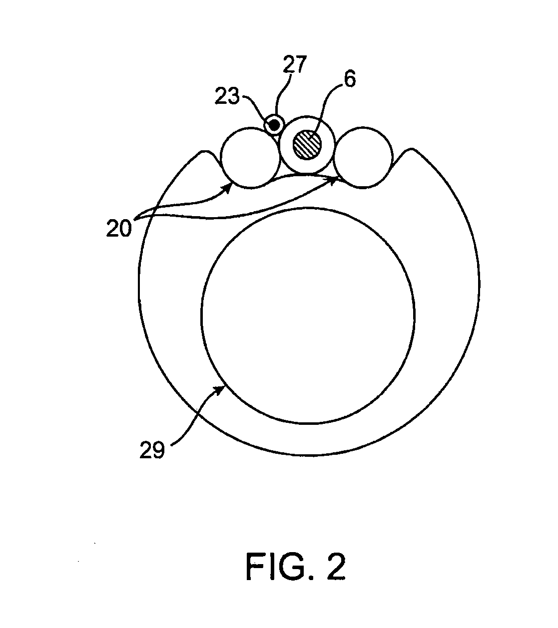
One or more lumens 20 extends through the device 2 and are used to deliver one or more fasteners 22 to maintain the tissue fold (see FIGS. 2 and 8). The fastener 22 may be any suitable fastener and one such fastener 22 is described in U.S. Ser. No. 10/949,737, which is incorporated herein by reference. A proximal end 19 of the fastener extends from the device for manipulation by the user.
A centering mechanism 23 is also provided for centering and manipulating the tissue engaging element 6. The centering mechanism 23 may be a wire loop 25 which is looped around the element 6. The wire loop 25 may be tensioned to move the tissue engaging element 6 from the position of FIG. 4 to the position of FIG. 5 in which the element 6 is oriented substantially perpendicular to the longitudinal axis of the device 2. The wire loop 25 extends through a lumen 27 as shown in the cross-sectional view of FIG. 2. The tissue engaging element 6 is free to slide within the wire loop 25, however, the wire loop is not large enough to permit the coil to pass therethrough so that the wire loop 25 is eventually drawn back with the tissue engaging element 6.
Use of the device 2 is now described with reference to FIGS. 3-8. The following method relates to use in the stomach but the device 2 may find uses in other areas as well without departing from the scope of the invention. The device 2 is introduced down the patient's throat to the desired location for creating a tissue fold. An endoscope (not shown) is used to guide the device 2 to the desired location and is introduced through a lumen 29. The device 2 may pass through the endoscope or the two may extend side by side as is known in the art without departing from the scope of the invention. The centering mechanism 23 is then tensioned to move the element 6 to the position of FIG. 5 so that the coil 8 is perpendicular to the longitudinal axis of the mold. The helical coil 8 is then rotated into engagement with tissue. Once engaged with tissue, the coil 8 and tissue are permitted to return to their respective free states rotationally. The helical coil 8 is then locked against rotation in preparation for manipulating the tissue as described below.
The mold 4 is then oriented so that it will create a fold, which is aligned in the desired direction. The area around the device 2 may then be reduced in volume using vacuum. The lumen 20, lumen 29 or another independent lumen or device may be used to evacuate air from the area around the device 2. The helical coil 8 is then slowly drawn back into the mold 4 while the area around the device 2 is reduced in volume. As the tissue enters the mold 4, the tissue fold is compressed as it enters the opening 14 so that the entire fold is compressed and drawn through the relatively small opening 14. In this manner, tissue connections and adhesions on the far side of the tissue layers, which form the tissue fold may be released prior to forming the fold.
The coil 8 is then moved proximally to draw the tissue through the opening 14 and into the recess 16. As the coil 8 continues to draw the tissue into the recess 16, the lateral edges of the tissue extend through the lateral openings 18. One or more of the fasteners 22 are then deployed through the lumen 20 to secure the tissue fold.
The present invention has been described with respect to a preferred embodiment, however, it is understood that numerous modifications and alterations could be made without departing from the scope of the invention. For example, the lateral openings could be linear rather than curved and the fastener may be an adhesive rather than a mechanical fastener.
* * * * *
D00000
D00001
D00002
D00003
D00004
XML
uspto.report is an independent third-party trademark research tool that is not affiliated, endorsed, or sponsored by the United States Patent and Trademark Office (USPTO) or any other governmental organization. The information provided by uspto.report is based on publicly available data at the time of writing and is intended for informational purposes only.
While we strive to provide accurate and up-to-date information, we do not guarantee the accuracy, completeness, reliability, or suitability of the information displayed on this site. The use of this site is at your own risk. Any reliance you place on such information is therefore strictly at your own risk.
All official trademark data, including owner information, should be verified by visiting the official USPTO website at www.uspto.gov. This site is not intended to replace professional legal advice and should not be used as a substitute for consulting with a legal professional who is knowledgeable about trademark law.