Systems and methods for exhaust heat recovery and heat storage
Taylor , et al. October 1, 2
U.S. patent number 10,428,713 [Application Number 15/698,021] was granted by the patent office on 2019-10-01 for systems and methods for exhaust heat recovery and heat storage. This patent grant is currently assigned to DENSO International America, Inc.. The grantee listed for this patent is DENSO International America, Inc.. Invention is credited to Alec Bergweiler, Mark Kastner, Zhiwei Shan, Dwayne Taylor.


| United States Patent | 10,428,713 |
| Taylor , et al. | October 1, 2019 |
Systems and methods for exhaust heat recovery and heat storage
Abstract
An exhaust heat recovery system. The system includes a heat exchanger configured to transfer heat from engine exhaust to a heat transfer fluid. A reservoir is in fluid communication with the heat exchanger. A pump is configured to pump the heat transfer fluid out of the heat exchanger and into the reservoir, and in doing so displace air out of the reservoir to the heat exchanger, when temperature of the heat transfer fluid exceeds a predetermined temperature.
| Inventors: | Taylor; Dwayne (Livonia, MI), Bergweiler; Alec (Leverett, MA), Shan; Zhiwei (Farmington Hills, MI), Kastner; Mark (Livonia, MI) | ||||||||||
|---|---|---|---|---|---|---|---|---|---|---|---|
| Applicant: |
|
||||||||||
| Assignee: | DENSO International America,
Inc. (Southfield, MI) |
||||||||||
| Family ID: | 65517445 | ||||||||||
| Appl. No.: | 15/698,021 | ||||||||||
| Filed: | September 7, 2017 |
Prior Publication Data
| Document Identifier | Publication Date | |
|---|---|---|
| US 20190072018 A1 | Mar 7, 2019 | |
| Current U.S. Class: | 1/1 |
| Current CPC Class: | F01P 7/16 (20130101); F01N 5/02 (20130101); F02N 19/02 (20130101); F02D 41/0255 (20130101); F02N 19/10 (20130101); Y02T 10/12 (20130101); F02D 2013/0292 (20130101); F01P 2060/08 (20130101); F01N 2240/02 (20130101); F02G 2260/00 (20130101); F01P 2060/16 (20130101) |
| Current International Class: | F01P 11/14 (20060101); F02N 19/02 (20100101); F01P 7/16 (20060101); F01N 5/02 (20060101); F02D 13/02 (20060101); F02D 41/02 (20060101) |
| Field of Search: | ;123/676 ;60/284,295,298,300,303,320,321 |
References Cited [Referenced By]
U.S. Patent Documents
| 3665949 | May 1972 | Rivard |
| 3686893 | August 1972 | Edwards |
| 3804596 | April 1974 | Fischer |
| 3888084 | June 1975 | Hawkins |
| 4137965 | February 1979 | Fallon, Jr. et al. |
| 4161211 | July 1979 | Duffy et al. |
| 4175397 | November 1979 | Edwards et al. |
| 4202660 | May 1980 | Pei |
| 4220197 | September 1980 | Schaefer et al. |
| 4248297 | February 1981 | Pei |
| 4284421 | August 1981 | Howard |
| 4285206 | August 1981 | Koser |
| 4301649 | November 1981 | Walker |
| 4342200 | August 1982 | Lowi, Jr. |
| 4373573 | February 1983 | Madwed |
| 4391235 | July 1983 | Majkrzak |
| 4393656 | July 1983 | Anderson et al. |
| 4409932 | October 1983 | Gill |
| 4414926 | November 1983 | Webber |
| 4422370 | December 1983 | Gustavson |
| 4448028 | May 1984 | Chao et al. |
| 4494598 | January 1985 | DeHaan et al. |
| 4532983 | August 1985 | Bradshaw et al. |
| 4629479 | December 1986 | Cantoni |
| 4688537 | August 1987 | Calkins et al. |
| 4694654 | September 1987 | Kawamura |
| 4777796 | October 1988 | McEachern, Jr. |
| 4805409 | February 1989 | Kobayashi |
| 4850537 | July 1989 | Gourdine |
| 5044423 | September 1991 | Schatz |
| 5106590 | April 1992 | Hopper et al. |
| 5231849 | August 1993 | Rosenblatt |
| 5291738 | March 1994 | Waldrop |
| 5327739 | July 1994 | Ingersoll et al. |
| 5351487 | October 1994 | Abdelmalek |
| 5366151 | November 1994 | King et al. |
| 5398747 | March 1995 | Miaoulis |
| 5400596 | March 1995 | Shlien |
| 5450894 | September 1995 | Inoue et al. |
| 5482402 | January 1996 | Nelson |
| 5503222 | April 1996 | Dunne |
| 5507153 | April 1996 | Seto et al. |
| 5516571 | May 1996 | Kawamoto |
| 5667560 | September 1997 | Dunne |
| 5708306 | January 1998 | Lin |
| 5730089 | March 1998 | Morikawa et al. |
| 5746259 | May 1998 | Noble, III |
| 5799632 | September 1998 | Bennett |
| 5894834 | April 1999 | Kim |
| 5934360 | August 1999 | Ban et al. |
| 5944090 | August 1999 | Teal |
| 5969189 | October 1999 | Holtzapple et al. |
| 5994681 | November 1999 | Lloyd |
| 6079218 | June 2000 | Ueda |
| 6151891 | November 2000 | Bennett |
| 6286316 | September 2001 | Waldrop et al. |
| 6340013 | January 2002 | Britton |
| 6415607 | July 2002 | Gray, Jr. |
| 6435420 | August 2002 | Kasai et al. |
| 6481222 | November 2002 | Denniston |
| 6627330 | September 2003 | Shimizu et al. |
| 6630113 | October 2003 | Surma |
| 6655137 | December 2003 | Sardari |
| 6675437 | January 2004 | York |
| 6675882 | January 2004 | Luberda |
| 6680619 | January 2004 | Horn |
| 6698389 | March 2004 | Andrews et al. |
| 6725662 | April 2004 | Baba et al. |
| 6746515 | June 2004 | Wegeng et al. |
| 6832475 | December 2004 | Tanaka et al. |
| 6843312 | January 2005 | Burk et al. |
| 6845618 | January 2005 | Niikura et al. |
| 6865825 | March 2005 | Bailey, Sr. et al. |
| 6866092 | March 2005 | Molivadas |
| 6907734 | June 2005 | Shinohara et al. |
| 6948319 | September 2005 | Hayakawa et al. |
| 6983105 | January 2006 | Greene |
| 7021059 | April 2006 | Shinohara et al. |
| 7043920 | May 2006 | Viteri et al. |
| 7055315 | June 2006 | Shinohara et al. |
| 7062915 | June 2006 | Clawson |
| 7069977 | July 2006 | Shinohara et al. |
| 7073348 | July 2006 | Clodic et al. |
| 7171991 | February 2007 | Aoyama et al. |
| 7181918 | February 2007 | Reinders |
| 7220365 | May 2007 | Qu et al. |
| 7237602 | July 2007 | Arai et al. |
| 7281380 | October 2007 | Shinohara et al. |
| 7281703 | October 2007 | Inaba et al. |
| 7430865 | October 2008 | Filippone |
| 7430875 | October 2008 | Sasaki et al. |
| 7629530 | December 2009 | Inaoka |
| 7654232 | February 2010 | Ishimaru et al. |
| 7654312 | February 2010 | Baeuerle |
| 8069906 | December 2011 | Mukoubara et al. |
| 8151753 | April 2012 | Kamiyama et al. |
| 8223495 | July 2012 | Carlson et al. |
| 8297049 | October 2012 | Ohtani |
| 8333068 | December 2012 | Muramatsu |
| 8371512 | February 2013 | Douarre |
| 8396645 | March 2013 | Bakharev |
| 8397504 | March 2013 | Guzman et al. |
| 8491678 | July 2013 | Bossard |
| 8574507 | November 2013 | Obuchi et al. |
| RE45644 | August 2015 | Cheiky |
| 9140168 | September 2015 | Reynolds |
| 9140500 | September 2015 | Goto et al. |
| 9145812 | September 2015 | An et al. |
| 9181866 | November 2015 | Jensen et al. |
| 9205347 | December 2015 | Batty et al. |
| 9228472 | January 2016 | Greiner et al. |
| 9234482 | January 2016 | Bromberg et al. |
| 9243821 | January 2016 | Hasegawa |
| 9249475 | February 2016 | Kawano et al. |
| 9297292 | March 2016 | Takeuchi |
| 9297564 | March 2016 | Wagaman et al. |
| 9328657 | May 2016 | Ulrey et al. |
| 9382799 | July 2016 | Stahlkopf et al. |
| 9395123 | July 2016 | Leimkuehler et al. |
| 2002/0081253 | June 2002 | Abe |
| 2002/0134542 | September 2002 | Unsworth |
| 2002/0157810 | October 2002 | Damson et al. |
| 2004/0031388 | February 2004 | Hsu |
| 2004/0164467 | August 2004 | Aoyama et al. |
| 2005/0019139 | January 2005 | Aoyama et al. |
| 2005/0081681 | April 2005 | Yamaki et al. |
| 2005/0103487 | May 2005 | Aflekt et al. |
| 2005/0204762 | September 2005 | Sasaki et al. |
| 2005/0217714 | October 2005 | Nishijima et al. |
| 2005/0262858 | December 2005 | Inaba et al. |
| 2005/0274493 | December 2005 | Golben |
| 2006/0070560 | April 2006 | Nakazawa |
| 2006/0162829 | July 2006 | Nakazawa et al. |
| 2006/0231235 | October 2006 | Yamanaka et al. |
| 2007/0137594 | June 2007 | Boudard et al. |
| 2007/0137851 | June 2007 | Hamada et al. |
| 2007/0193617 | August 2007 | Taguchi |
| 2007/0284087 | December 2007 | Kohara et al. |
| 2008/0011458 | January 2008 | Miyagawa et al. |
| 2008/0034729 | February 2008 | Tafas |
| 2008/0035195 | February 2008 | Bell |
| 2008/0110421 | May 2008 | Flessner et al. |
| 2008/0115487 | May 2008 | Harada et al. |
| 2008/0115923 | May 2008 | Yamanaka et al. |
| 2008/0257535 | October 2008 | Cournane |
| 2009/0183697 | July 2009 | Inui |
| 2009/0205342 | August 2009 | Jang et al. |
| 2009/0229796 | September 2009 | Williams et al. |
| 2009/0241863 | October 2009 | Kimura et al. |
| 2009/0267349 | October 2009 | Spitzauer et al. |
| 2009/0301601 | December 2009 | Enerson et al. |
| 2010/0006073 | January 2010 | Jatkar |
| 2010/0006273 | January 2010 | Du et al. |
| 2010/0017638 | January 2010 | Ghose |
| 2010/0043413 | February 2010 | Orihashi et al. |
| 2010/0043427 | February 2010 | Sawada et al. |
| 2010/0146949 | June 2010 | Stobart et al. |
| 2010/0186422 | July 2010 | Yang et al. |
| 2010/0193168 | August 2010 | Johnson, Jr. |
| 2010/0197441 | August 2010 | Pursifull |
| 2010/0218930 | September 2010 | Proeschel |
| 2010/0236763 | September 2010 | Torok |
| 2010/0270011 | October 2010 | Takahashi et al. |
| 2010/0314089 | December 2010 | Evans-Beauchamp |
| 2011/0036320 | February 2011 | Peret |
| 2011/0088378 | April 2011 | Prior et al. |
| 2011/0107761 | May 2011 | Rowland |
| 2011/0126783 | June 2011 | Hwang et al. |
| 2011/0180235 | July 2011 | Garimella et al. |
| 2011/0185712 | August 2011 | Burns et al. |
| 2011/0239646 | October 2011 | Bennet et al. |
| 2011/0284200 | November 2011 | Gooden et al. |
| 2012/0012293 | January 2012 | Doty |
| 2012/0048504 | March 2012 | Park et al. |
| 2012/0152487 | June 2012 | Styles et al. |
| 2012/0216762 | August 2012 | Ernst et al. |
| 2012/0247732 | October 2012 | Suzuki et al. |
| 2012/0260640 | October 2012 | Martin et al. |
| 2012/0273158 | November 2012 | Cui et al. |
| 2012/0312497 | December 2012 | Parida et al. |
| 2013/0025842 | January 2013 | Carlson et al. |
| 2013/0037235 | February 2013 | Sakabe et al. |
| 2013/0037254 | February 2013 | Carlson et al. |
| 2013/0174544 | July 2013 | Valetutti |
| 2013/0213632 | August 2013 | Morita et al. |
| 2013/0240284 | September 2013 | Ajisaka |
| 2013/0248159 | September 2013 | Yoshida et al. |
| 2013/0248160 | September 2013 | Eplee |
| 2013/0299599 | November 2013 | Mihama et al. |
| 2013/0319027 | December 2013 | Tsubouchi |
| 2014/0020877 | January 2014 | Suzuki et al. |
| 2014/0026577 | January 2014 | Reinke et al. |
| 2014/0060044 | March 2014 | Gonze et al. |
| 2014/0060086 | March 2014 | Ranalli et al. |
| 2014/0090821 | April 2014 | Suzuki et al. |
| 2014/0102683 | April 2014 | Kawaguchi et al. |
| 2014/0103129 | April 2014 | Ray et al. |
| 2014/0109976 | April 2014 | Mathias et al. |
| 2014/0123626 | May 2014 | Brown et al. |
| 2014/0208752 | July 2014 | Palanisamy |
| 2014/0290296 | October 2014 | Katoh |
| 2015/0053366 | February 2015 | Melsheimer |
| 2015/0128590 | May 2015 | Engineer et al. |
| 2015/0143806 | May 2015 | Friesth |
| 2015/0176464 | June 2015 | Hotta et al. |
| 2015/0176913 | June 2015 | Buckrell et al. |
| 2015/0226154 | August 2015 | Ueda et al. |
| 2015/0273974 | October 2015 | Levin et al. |
| 2015/0323265 | November 2015 | Hodsdon et al. |
| 2015/0360539 | December 2015 | Park et al. |
| 2016/0069624 | March 2016 | Rollins et al. |
| 2016/0084197 | March 2016 | Davis |
| 2016/0116224 | April 2016 | Shedd et al. |
| 2016/0138427 | May 2016 | Yin et al. |
| 2016/0169080 | June 2016 | Lee et al. |
| 2016/0169081 | June 2016 | Hosokawa |
| 2016/0187009 | June 2016 | Vandermeulen et al. |
| 2016/0215680 | July 2016 | Quix |
| 1192949 | Sep 1985 | CA | |||
| 2209253 | Jan 1999 | CA | |||
| 2251095 | May 2003 | CA | |||
| 2522952 | Apr 2006 | CA | |||
| 2880357 | Aug 2015 | CA | |||
| 2302914 | Jan 1999 | CN | |||
| 2392684 | Aug 2000 | CN | |||
| 101408115 | Apr 2003 | CN | |||
| 101368525 | Feb 2009 | CN | |||
| 201203373 | Mar 2009 | CN | |||
| 101408115 | Apr 2009 | CN | |||
| 101451484 | Jun 2009 | CN | |||
| 201696124 | Jan 2011 | CN | |||
| 103105085 | May 2013 | CN | |||
| 202912813 | May 2013 | CN | |||
| 203240934 | Oct 2013 | CN | |||
| 103470352 | Dec 2013 | CN | |||
| 203515746 | Apr 2014 | CN | |||
| 203515747 | Apr 2014 | CN | |||
| 103982328 | Aug 2014 | CN | |||
| 203783758 | Aug 2014 | CN | |||
| 204172884 | Feb 2015 | CN | |||
| 103075275 | Apr 2015 | CN | |||
| 204646383 | Sep 2015 | CN | |||
| 105317584 | Feb 2016 | CN | |||
| 102013107251 | Jan 2015 | DE | |||
| 0133428 | Feb 1985 | EP | |||
| 0016225 | Oct 1987 | EP | |||
| 0294146 | May 1992 | EP | |||
| 0992377 | Apr 2000 | EP | |||
| 0767081 | Dec 2001 | EP | |||
| 1198675 | Apr 2002 | EP | |||
| 0871537 | Nov 2003 | EP | |||
| 1610084 | Dec 2005 | EP | |||
| 1774230 | Apr 2007 | EP | |||
| 1970971 | Sep 2008 | EP | |||
| 2018285 | Jan 2009 | EP | |||
| 2055515 | May 2009 | EP | |||
| 2263056 | Dec 2010 | EP | |||
| 2228615 | Jun 2011 | EP | |||
| 1970972 | Sep 2011 | EP | |||
| 2318676 | Nov 2011 | EP | |||
| 2444509 | Apr 2012 | EP | |||
| 2480851 | Aug 2012 | EP | |||
| 2500530 | Sep 2012 | EP | |||
| 2596225 | May 2013 | EP | |||
| 2503134 | Sep 2013 | EP | |||
| 2735597 | May 2014 | EP | |||
| 2806131 | Nov 2014 | EP | |||
| 2811142 | Jul 2015 | EP | |||
| 2282357 | Dec 2015 | EP | |||
| 2952705 | Dec 2015 | EP | |||
| 2459886 | Jan 1981 | FR | |||
| 2489418 | Mar 1982 | FR | |||
| 2718491 | Jun 1996 | FR | |||
| 2774462 | Apr 2000 | FR | |||
| 2810076 | May 2005 | FR | |||
| 2921689 | Apr 2009 | FR | |||
| 2997446 | Dec 2014 | FR | |||
| 797783 | Jul 1958 | GB | |||
| 1345970 | Feb 1974 | GB | |||
| 1426790 | Mar 1976 | GB | |||
| 2432205 | May 2007 | GB | |||
| S58158949 | Oct 1983 | JP | |||
| 2000297699 | Oct 2000 | JP | |||
| 2004036499 | Feb 2004 | JP | |||
| 2016511355 | Apr 2016 | JP | |||
| 19980060686 | Oct 1998 | KR | |||
| 20010090620 | Oct 2001 | KR | |||
| 20020037964 | May 2002 | KR | |||
| 20080012435 | Feb 2008 | KR | |||
| 100808789 | Mar 2008 | KR | |||
| 101129197 | Mar 2012 | KR | |||
| 20130058996 | Jun 2013 | KR | |||
| WO-8402857 | Aug 1984 | WO | |||
| WO-1994002257 | Mar 1994 | WO | |||
| WO-1999022120 | May 1999 | WO | |||
| WO-0106134 | Jan 2001 | WO | |||
| WO-2001014813 | Mar 2001 | WO | |||
| WO-2002097354 | Dec 2002 | WO | |||
| WO-2005103453 | Nov 2005 | WO | |||
| WO-2005121660 | Dec 2005 | WO | |||
| WO-2006012087 | Aug 2006 | WO | |||
| WO-2007132326 | Nov 2007 | WO | |||
| WO-2009050534 | Apr 2009 | WO | |||
| WO-2009076637 | Jun 2009 | WO | |||
| WO-2009112946 | Sep 2009 | WO | |||
| WO-2009156786 | Dec 2009 | WO | |||
| WO-2010031162 | Nov 2010 | WO | |||
| WO-2011037596 | Mar 2011 | WO | |||
| WO-2011073470 | Jun 2011 | WO | |||
| WO-2012010960 | Jan 2012 | WO | |||
| WO-2013116861 | Aug 2013 | WO | |||
| WO-2013167823 | Nov 2013 | WO | |||
| WO-2011066964 | Feb 2014 | WO | |||
| WO-2014052310 | Apr 2014 | WO | |||
| WO-2014136024 | Sep 2014 | WO | |||
| WO-2014165147 | Oct 2014 | WO | |||
| WO-2015034448 | Mar 2015 | WO | |||
| WO-2010109145 | Aug 2015 | WO | |||
| WO-2015168018 | Nov 2015 | WO | |||
| WO-2016000016 | Jan 2016 | WO | |||
| WO-2016010266 | Jan 2016 | WO | |||
| WO-2016038384 | Mar 2016 | WO | |||
| WO-2016065048 | Apr 2016 | WO | |||
Assistant Examiner: Laguarda; Gonzalo
Attorney, Agent or Firm: Harness, Dickey & Pierce, P.L.C.
Claims
What is claimed is:
1. An exhaust heat recovery system comprising: a heat exchanger configured to transfer heat from engine exhaust to a heat transfer fluid; a reservoir in fluid communication with the heat exchanger; and a pump configured to pump the heat transfer fluid out of the heat exchanger and into the reservoir, and in doing so displace air out of the reservoir to the heat exchanger, when temperature of the heat transfer fluid exceeds a predetermined temperature; wherein the heat exchanger includes an outer chamber arranged outside a flow path of the engine exhaust, the outer chamber having: a first inlet for heat transfer fluid flowing from the engine; a second inlet separate from the first inlet for heat transfer fluid or air flowing from the reservoir; and an outlet separate from the first inlet and the second inlet for heat transfer fluid and air.
2. The system of claim 1, wherein the heat exchanger defines a single through bore for accommodating exhaust.
3. The system of claim 1, wherein the reservoir is arranged above the heat exchanger such that gravity draws heat transfer fluid within the reservoir to flow to the heat exchanger.
4. The system of claim 1, further comprising at least one valve selectively providing fluid communication between the heat exchanger, the reservoir, and the engine.
5. The system of claim 4, wherein the pump is between the at least one valve and the reservoir along a fluid line extending therebetween.
6. The system of claim 1, wherein the pump is an electric pump.
7. The system of claim 1, further comprising a two-way valve between the heat exchanger and the engine along a fluid line extending therebetween.
8. The system of claim 1, wherein the pump is the only pump of a combined exhaust heat recovery system and engine cooling system.
9. The system of claim 1, further comprising a bypass fluid line directing heat transfer fluid or air around the heat exchanger so that the heat transfer fluid or air does not flow through the heat exchanger.
10. The system of claim 1, wherein at least one valve is configured to direct heat transfer fluid from the heat exchanger to the engine, and not to the reservoir, in a heat recovery mode.
11. The system of claim 1, wherein the pump pumps heat transfer fluid from the heat exchanger through at least one valve to the reservoir and in doing so displaces air from the reservoir into the heat exchanger in a pump out mode; and wherein the at least one valve is configured to block flow of heat transfer fluid through the at least one valve to the engine in the pump out mode.
12. The system of claim 1, wherein the heat exchanger is a first heat exchanger, the system further comprising a second heat exchanger that exchanges heat between first heat transfer fluid flowing through the exhaust heat recovery system and second heat transfer fluid that flows directly through an engine producing the engine exhaust; and wherein the first heat transfer fluid is the same as, or different than, the second heat transfer fluid.
13. The system of claim 1, wherein at least one valve allows heat transfer fluid to flow under the influence of gravity backwards through the pump from the reservoir into the heat exchanger, and in doing so displaces air out of the heat exchanger and into the reservoir in a refill mode; and wherein the at least one valve is configured to block flow of heat transfer fluid through the at least one valve to the engine in the refill mode.
Description
FIELD
The present disclosure relates to systems and methods for exhaust heat recovery and heat storage.
BACKGROUND
This section provides background information related to the present disclosure, which is not necessarily prior art.
Due to the increasingly stringent fuel economy and CO.sub.2 emissions regulations, automakers are developing numerous technologies to reduce fuel consumption. For example, exhaust heat recovery systems are used to facilitate engine warmup, which improves fuel economy. Such systems typically include a heat exchanger, which transfers heat from exhaust gas to engine heat transfer fluid during a cold engine start. This shortens the time needed for heat transfer fluid to reach its optimal operating temperature and, by extension, the time required for the engine to warm up and reach its optimal operating temperature.
With exhaust heat recovery systems it is not desirable to have a heat exchanger operational at all times, because the engine may overheat and/or the engine heat transfer fluid may be damaged by high exhaust temperatures. Existing exhaust heat recovery systems typically address these issues by using a diverter valve that opens when the engine is sufficiently warm to direct exhaust to bypass the heat exchanger, which prevents the heat transfer fluid from overheating. This approach places the heat exchanger in parallel with the normal exhaust system routing, which undesirably adds to the packaging space (which can be a bigger problem for vehicles with larger exhaust system components, such as pickup trucks), adds cost due to the need for exhaust diverter valves (which are typically stainless steel in order to provide resistance to temperature and corrosive exhaust gasses), and changes the exhaust back pressure characteristics, which typically complicates the engine calibration process.
The present teachings advantageously provide for an exhaust heat recovery system that does not intrude into the exhaust system itself (or minimizes such intrusion if exhaust side heat transfer enhancements such as multiple flow paths and/or exhaust side fins are included), or require dual exhaust system pathways (one for when exhaust heat recovery is operational, and one for when it is not operational) as found in conventional systems. In contrast to current systems, the present teachings advantageously remove heat transfer fluid from the exhaust heat recovery heat exchanger when heat recovery is not needed, and return the heat transfer fluid into the heat exchanger when exhaust heat recovery is desired, which prevents overheating of the heat transfer fluid. Furthermore, in one embodiment the present teachings advantageously combine exhaust heat recovery and heat storage into a single system, as explained in detail herein. The present teachings are particularly advantageous because exhaust heat recovery and heat storage are the two most effective ways to improve fuel economy by thermal management. One skilled in the art will appreciate that the present teachings provide for numerous additional advantages in addition to those specifically described, as well as numerous unexpected results.
SUMMARY
This section provides a general summary of the disclosure, and is not a comprehensive disclosure of its full scope or all of its features.
The present teachings provide for an exhaust heat recovery system. The system includes a heat exchanger configured to transfer heat from engine exhaust to a heat transfer fluid. A reservoir is in fluid communication with the heat exchanger. A pump is configured to pump the heat transfer fluid out of the heat exchanger and into the reservoir, and in doing so displace air out of the reservoir to the hear exchanger, when temperature of the heat transfer fluid exceeds a predetermined temperature.
Further areas of applicability will become apparent from the description provided herein. The description and specific examples in this summary are intended for purposes of illustration only and are not intended to limit the scope of the present disclosure.
DRAWINGS
The drawings described herein are for illustrative purposes only of select embodiments and not all possible implementations, and are not intended to limit the scope of the present disclosure.
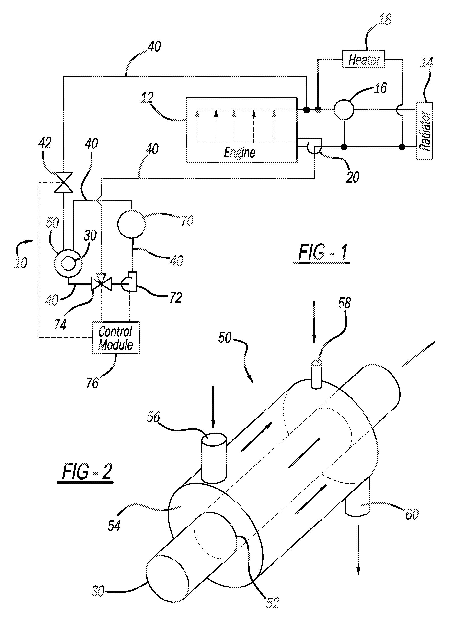
FIG. 1 illustrates an exemplary exhaust heat recovery and heat storage system according to the present teachings connected to an exemplary engine;
FIG. 2 illustrates an exemplary heat exchanger of the exhaust heat recovery and heat storage system of FIG. 1;
FIG. 3 illustrates the exhaust heat recovery and heat storage system of FIG. 1 in a heat recovery mode;
FIG. 4 illustrates the exhaust heat recovery and heat storage system of FIG. 1 in a pump out mode;
FIG. 5 illustrates the exhaust heat recovery and heat storage system of FIG. 1 in a standby mode;
FIG. 6 illustrates the exhaust heat recovery and heat storage system of FIG. 1 in a refill mode;
FIG. 7 illustrates the exhaust heat recovery and heat storage system of FIG. 1, and a secondary heat exchanger that transfers heat to and from the exhaust heat recovery and heat storage system of FIG. 1; and
FIG. 8 illustrates another exemplary exhaust heat recovery and heat storage system according to the present teachings connected to an exemplary engine
Corresponding reference numerals indicate corresponding parts throughout the several views of the drawings.
DETAILED DESCRIPTION
Example embodiments will now be described more fully with reference to the accompanying drawings.
With initial reference to FIG. 1, an exhaust heat recovery and heat storage system in accordance with the present teachings is illustrated at reference numeral 10. As explained herein, the system 10 generally receives heat transfer fluid from an engine 12, transfers heat to the heat transfer fluid from exhaust generated by the engine 12, and directs the warmed heat transfer fluid back to the engine 12 in order to facilitate warmup of the engine 12. The heat transfer fluid may be any suitable heat transfer fluid for the engine 12. For example, the heat transfer fluid can be a 50/50 mixture of ethylene glycol and water, or any other suitable heat transfer fluid. The engine 12 can be any suitable type of engine, such as any suitable vehicle engine. Exemplary vehicle engines include engines for passenger vehicles, mass transit vehicles, military vehicles, construction vehicles, aircraft, watercraft, etc. The engine 12 can also be any suitable non-vehicular engine, such as a generator engine, construction equipment engine, etc.
In the example illustrated, a radiator 14 is in fluid communication with the engine 12. When heat transfer fluid of the engine 12 exceeds a predetermined temperature, such as measured by thermostat 16, the heat transfer fluid can be directed to the radiator 14, which releases heat from the heat transfer fluid into the atmosphere. Warmed heat transfer fluid can also be circulated through a heater 18, which can be a passenger cabin heater for heating a vehicle passenger cabin. Any suitable pump 20 may be included to pump the heat transfer fluid through the engine 12.
The system 10 further includes any suitable heat exchanger 50 for transferring heat to the heat transfer fluid from exhaust generated by the engine 12. In the example illustrated, the heat exchanger 50 defines a through bore 52 through which an exhaust pipe 30 of the engine 12 extends, as illustrated in FIG. 2 for example. An outer chamber 54 of the heat exchanger 50 surrounds the exhaust pipe 30 such that heat transfer fluid within the outer chamber 54 is warmed by exhaust flowing through the exhaust pipe 30.
The heat exchanger 50 includes an engine inlet 56, a reservoir inlet 58, and a passageway 60, each of which are connected to any suitable conduits 40 for transporting heat transfer fluid. The conduits 40 can be any suitable conduit, such as any suitable pipe or hose. Along the conduit 40 extending from the engine 12 to the heat exchanger 50 is a valve 42. The valve 42 can be any suitable valve or device for controlling flow of heat transfer fluid from the engine 12 to the heat exchanger 50.
The engine inlet 56 receives heat transfer fluid from the engine 12. Thus the engine inlet 56 is in fluid communication with the engine 12 to receive heat transfer fluid that has been circulated through the engine 12. The heat transfer fluid flows through the inlet 56, through the chamber 54, and out of the heat exchanger 50 through the passageway 60. The reservoir inlet 58 is connected to a reservoir 70 with any suitable conduit 40 so as to allow air (or in some applications nitrogen, or any other inert gas) to flow between the reservoir 70 and the chamber 54 of the heat exchanger 50 as described herein.
The reservoir 70 is for storing the heat transfer fluid and/or air or any other suitable gas, such as nitrogen. The reservoir 70 can be mounted at a higher elevation than the heat exchanger 50 to allow heat transfer fluid within the reservoir 70 to flow to the heat exchanger 50 by gravity. Arranged along conduits 40 connecting the reservoir 70 to the heat exchanger 50 is a pump 72. The pump 72 can be any suitable pump, such as an electric pump. Between the pump 72 and the heat exchanger 50 is a valve 74. The valve 74 can be any suitable valve or other device for selectively directing heat transfer fluid between the heat exchanger 50 and the reservoir 70, from the heat exchanger 50 to the engine 12, or from the reservoir 70 to the engine 12, as explained herein.
The valve 42, the pump 72, and the valve 74 can be controlled by any suitable control module 76 to control the flow of heat transfer fluid, as explained in detail herein. Any suitable control module 76 can be used. In this application, including the definitions below, the term "control module" may be replaced with the term "circuit." The term "module" may refer to, be part of, or include processor hardware (shared, dedicated, or group) that executes code and memory hardware (shared, dedicated, or group) that stores code executed by the processor hardware. The code is configured to provide the features of the control module 76 described herein. The term memory hardware is a subset of the term computer-readable medium. The term computer-readable medium, as used herein, does not encompass transitory electrical or electromagnetic signals propagating through a medium (such as on a carrier wave); the term computer-readable medium is therefore considered tangible and non-transitory. Non-limiting examples of a non-transitory computer-readable medium are nonvolatile memory devices (such as a flash memory device, an erasable programmable read-only memory device, or a mask read-only memory device), volatile memory devices (such as a static random access memory device or a dynamic random access memory device), magnetic storage media (such as an analog or digital magnetic tape or a hard disk drive), and optical storage media (such as a CD, a DVD, or a Blu-ray Disc).
FIG. 3 illustrates the system 10 in an exemplary heat recovery mode. In the heat recovery mode of FIG. 3, the control module 76 opens the valve 42 to allow heat transfer fluid to flow from the engine 12 into the chamber 54 through the engine inlet 56. As the heat transfer fluid flows through the chamber 54, the heat transfer fluid is heated by warm exhaust gas flowing through the exhaust pipe 30. The heated heat transfer fluid exits the chamber 54 through the passageway 60, and flows to the valve 74. The control module 76 configures the valve 74 to direct the heated heat transfer fluid back to the engine 12 to help warm the engine 12 to a predetermined operating temperature. In the heat recovery mode of FIG. 3, the control module 76 does not activate the pump 72, and the reservoir 70 remains full, or at least partially full, of air, nitrogen, or any other suitable gas.
Once the heat transfer fluid has been sufficiently heated to a predetermined temperature by the exhaust (which will result in the engine 12 being warmed to a predetermined temperature), the control module 76 will close the valve 42 to prevent additional heat transfer fluid from flowing to the heat exchanger 50. The control module 76 will also reconfigure the valve 74 so that the heat transfer fluid no longer flows to the engine 12, but instead flows to the reservoir 70. The control module 76 also activates the pump 72 to pump the heat transfer fluid into the reservoir 70, and in doing so displace the air, nitrogen, or other gas within the reservoir 70 into the chamber 54 of the heat exchanger 50 through the reservoir inlet 58. This pump out mode of FIG. 4 advantageously prevents the heat transfer fluid from being overheated by exhaust flowing through the exhaust pipe 30, and prevents overheated heat transfer fluid from flowing to the engine 12, which may reduce performance of the engine 12 and/or undesirably affect the heat transfer fluid. Heat transfer fluid flowing through the engine 12 may be circulated through the radiator 14 to further prevent the heat transfer fluid and/or the engine 12 from becoming too warm.
After the reservoir 70 has been filled with heat transfer fluid and the heat exchanger 50 is filled with the air, nitrogen, or other suitable gas that was stored in reservoir 70, the control module 76 deactivates the pump 72 to configure the system 10 in the standby mode of FIG. 5. The valve 42 remains closed in the standby mode of FIG. 5. Once the temperature of the engine 12 falls below a predetermined temperature, such as at a cold engine start, the control module 76 configures the system 10 in a refill mode, as illustrated in FIG. 6. In the refill mode of FIG. 6, the control module 76 configures the valve 74 to allow heat transfer fluid stored in the reservoir 70 to flow through the valve 74 and into the chamber 54 of the heat exchanger 50. Because the reservoir 70 is arranged at an elevation higher than the heat exchanger 50, gravity will cause the heat transfer fluid to flow into the chamber 54 without the pump 72 having to be activated. As the heat transfer fluid flows from the reservoir 70 into the chamber 54, air within the chamber 54 is forced into the reservoir 70. Once exhaust flowing through the exhaust pipe 30 raises the temperature of the heat transfer fluid within the chamber 54 above a predetermined temperature, the control module 76 will configure the system 10 in the heat recovery mode of FIG. 3, whereby the heated heat transfer fluid is directed to the engine 12 to facilitate warmup of the engine 12.
If the reservoir 70 is well insulated, the coolant stored in the reservoir 70 during standby mode can remain hot after engine shut-down, and further accelerate engine warm-up if heat exchanger refill mode is not activated until engine cold start.
The system 10 can be directly connected to the engine 12 by way of conduits 40 as illustrated in FIG. 1. Alternatively, and with reference to FIG. 7, any suitable secondary heat exchanger 80 can be arranged between the system 10 and the engine 12. The secondary heat exchanger 80 can be any suitable heat exchanger for exchanging heat between heat transfer fluid flowing through the system 10 and heat transfer fluid flowing directly through the engine 12.
FIG. 8 illustrates another exemplary exhaust heat recovery and heat storage system in accordance with the present teachings at reference numeral 110. Unlike the configuration of FIG. 1, the configuration of FIG. 8 does not include the pump 20. Instead, the configuration of FIG. 8 includes only a single pump in the form of pump 72. The system 110 of FIG. 8 further includes a three-way valve 112 between the heat exchanger 50 and the pump 72, as well as a bypass line 120 extending around the heat exchanger 50 from another three-way valve 122 in order to direct flow of the heat transfer fluid around the heat exchanger 50.
During a cold engine start, for example, the control module 76 will activate the pump 72, configure the three-way valve 122 to allow heat transfer fluid to flow from the engine 12 through the valve 122 to the heat exchanger 50 instead of to the bypass line 120, completely open the three-way valve 112, and configure the three-way valve 74 such that heat transfer fluid pumped out of the heat exchanger 50 flows through the valve 112, across the pump 72, and through the valve 74 to the engine 12. The valve 74 is configured to block the passage of contents of the reservoir 70 through the valve 74.
In a pump out mode, the control module 76 activates the pump 72, completely closes the valve 122, configures the valve 112 such that heat transfer fluid within the heat exchanger 50 can be pumped out of the heat exchanger 50 to the valve 74, and through the valve 74 into the reservoir 70. A restrictor may be included between the valve 74 and the reservoir 70 since the pump 72 used in the single pump system of FIG. 8 will likely have a much higher flow rate than the pump 72 used in the dual pump system of FIG. 1.
During normal operation of the engine 12, the control module 76 may configure the system 110 in a standby mode. In the standby mode the control module 76 activates the pump 72 and configures the valve 122 to direct heat transfer fluid from the engine 12 to the bypass line 120, and thus block the flow of heat transfer fluid from the engine 12 through the valve 122 to the heat exchanger 50. The control module 76 configures the valve 112 to block passage of heat transfer fluid from the heat exchanger 50 through the valve 112. Instead, the valve 112 is configured to allow heat transfer fluid flowing from the bypass line 120 to pass through the valve 112 to the pump 72. The valve 74 is configured to allow the heat transfer fluid to flow from the pump 72 through the valve 74 and back to the engine 12. The valve 74 is configured to prevent contents of the reservoir 70 from flowing through the valve 74.
To refill the heat exchanger 50 with heat transfer fluid, the control module 76 deactivates the pump 72 and completely closes the valve 122. The valve 74 is configured to allow heat transfer fluid therein to flow through the valve 74 under the influence of gravity, and to the valve 112. The valve 112 is configured by the control module 76 to allow the heat transfer fluid from the reservoir 70 to flow through the valve 112 and into the heat exchanger 50 in order to refill the heat exchanger 50.
It will be recognized by one skilled in the art that the function provided by each three-way valve described in the above systems could also be accomplished by utilizing two or three two-way valves.
The foregoing description of the embodiments has been provided for purposes of illustration and description. It is not intended to be exhaustive or to limit the disclosure. Individual elements or features of a particular embodiment are generally not limited to that particular embodiment, but, where applicable, are interchangeable and can be used in a selected embodiment, even if not specifically shown or described. The same may also be varied in many ways. Such variations are not to be regarded as a departure from the disclosure, and all such modifications are intended to be included within the scope of the disclosure.
Example embodiments are provided so that this disclosure will be thorough, and will fully convey the scope to those who are skilled in the art. Numerous specific details are set forth such as examples of specific components, devices, and methods, to provide a thorough understanding of embodiments of the present disclosure. It will be apparent to those skilled in the art that specific details need not be employed, that example embodiments may be embodied in many different forms and that neither should be construed to limit the scope of the disclosure. In some example embodiments, well-known processes, well-known device structures, and well-known technologies are not described in detail.
The terminology used herein is for the purpose of describing particular example embodiments only and is not intended to be limiting. As used herein, the singular forms "a," "an," and "the" may be intended to include the plural forms as well, unless the context clearly indicates otherwise. The terms "comprises," "comprising," "including," and "having," are inclusive and therefore specify the presence of stated features, integers, steps, operations, elements, and/or components, but do not preclude the presence or addition of one or more other features, integers, steps, operations, elements, components, and/or groups thereof. The method steps, processes, and operations described herein are not to be construed as necessarily requiring their performance in the particular order discussed or illustrated, unless specifically identified as an order of performance. It is also to be understood that additional or alternative steps may be employed.
When an element or layer is referred to as being "on," "engaged to," "connected to," or "coupled to" another element or layer, it may be directly on, engaged, connected or coupled to the other element or layer, or intervening elements or layers may be present. In contrast, when an element is referred to as being "directly on," "directly engaged to," "directly connected to," or "directly coupled to" another element or layer, there may be no intervening elements or layers present. Other words used to describe the relationship between elements should be interpreted in a like fashion (e.g., "between" versus "directly between," "adjacent" versus "directly adjacent," etc.). As used herein, the term "and/or" includes any and all combinations of one or more of the associated listed items.
Although the terms first, second, third, etc. may be used herein to describe various elements, components, regions, layers and/or sections, these elements, components, regions, layers and/or sections should not be limited by these terms. These terms may be only used to distinguish one element, component, region, layer or section from another region, layer or section. Terms such as "first," "second," and other numerical terms when used herein do not imply a sequence or order unless clearly indicated by the context. Thus, a first element, component, region, layer or section discussed below could be termed a second element, component, region, layer or section without departing from the teachings of the example embodiments.
Spatially relative terms, such as "inner," "outer," "beneath," "below," "lower," "above," "upper," and the like, may be used herein for ease of description to describe one element or feature's relationship to another element(s) or feature(s) as illustrated in the figures. Spatially relative terms may be intended to encompass different orientations of the device in use or operation in addition to the orientation depicted in the figures. For example, if the device in the figures is turned over, elements described as "below" or "beneath" other elements or features would then be oriented "above" the other elements or features. Thus, the example term "below" can encompass both an orientation of above and below. The device may be otherwise oriented (rotated 90 degrees or at other orientations) and the spatially relative descriptors used herein interpreted accordingly.
* * * * *
D00000
D00001
D00002
D00003
D00004
XML
uspto.report is an independent third-party trademark research tool that is not affiliated, endorsed, or sponsored by the United States Patent and Trademark Office (USPTO) or any other governmental organization. The information provided by uspto.report is based on publicly available data at the time of writing and is intended for informational purposes only.
While we strive to provide accurate and up-to-date information, we do not guarantee the accuracy, completeness, reliability, or suitability of the information displayed on this site. The use of this site is at your own risk. Any reliance you place on such information is therefore strictly at your own risk.
All official trademark data, including owner information, should be verified by visiting the official USPTO website at www.uspto.gov. This site is not intended to replace professional legal advice and should not be used as a substitute for consulting with a legal professional who is knowledgeable about trademark law.