Trocar seal system
Racenet , et al. October 1, 2
U.S. patent number 10,426,516 [Application Number 11/786,251] was granted by the patent office on 2019-10-01 for trocar seal system. This patent grant is currently assigned to Covidien LP. The grantee listed for this patent is Joseph Pasqualucci, David C. Racenet, Gene A. Stellon, William J. Vumback. Invention is credited to Joseph Pasqualucci, David C. Racenet, Gene A. Stellon, William J. Vumback.


| United States Patent | 10,426,516 |
| Racenet , et al. | October 1, 2019 |
Trocar seal system
Abstract
A seal assembly is provided for reception of an elongated surgical instrument, which comprises a body having at least one opening configured and dimensioned to permit entry of an elongated surgical instrument and defining a central longitudinal axis; a seal member formed of a resilient material and defining an aperture therein, the aperture being configured and dimensioned such that insertion of the surgical instrument into the aperture causes the resilient material defining the aperture to resiliently contact the outer surface of the surgical instrument in a substantially fluid tight manner, the seal member further including a peripheral flange element which contacts a surface of the body to form a contact seal therewith; and a fabric layer juxtaposed relative to the resilient material. The seal assembly may further include a coating applied to the seal member to reduce friction between the seal member and surgical instrumentation inserted therein. The coating is preferably a hydrocyclosiloxane membrane prepared by plasma polymerization process.
| Inventors: | Racenet; David C. (Southbury, CT), Stellon; Gene A. (Southington, CT), Vumback; William J. (Northford, CT), Pasqualucci; Joseph (North Haven, CT) | ||||||||||
|---|---|---|---|---|---|---|---|---|---|---|---|
| Applicant: |
|
||||||||||
| Assignee: | Covidien LP (Mansfield,
MA) |
||||||||||
| Family ID: | 21952169 | ||||||||||
| Appl. No.: | 11/786,251 | ||||||||||
| Filed: | April 11, 2007 |
Prior Publication Data
| Document Identifier | Publication Date | |
|---|---|---|
| US 20070197972 A1 | Aug 23, 2007 | |
Related U.S. Patent Documents
| Application Number | Filing Date | Patent Number | Issue Date | ||
|---|---|---|---|---|---|
| 10268140 | Oct 9, 2002 | 7244244 | |||
| 09449368 | 6482181 | ||||
| PCT/US98/08970 | May 1, 1998 | ||||
| 60047989 | May 28, 1997 | ||||
| Current U.S. Class: | 1/1 |
| Current CPC Class: | A61B 17/3462 (20130101); A61B 17/3498 (20130101); A61M 39/0613 (20130101); A61M 39/0606 (20130101); F16K 15/147 (20130101); A61M 2039/0633 (20130101); A61M 2039/0653 (20130101); A61M 2039/0646 (20130101); A61M 2039/0686 (20130101); A61M 2039/0673 (20130101); A61B 2017/00526 (20130101); A61M 39/06 (20130101); Y10T 137/788 (20150401); Y10T 137/87804 (20150401); A61M 2039/0626 (20130101); A61B 2017/3464 (20130101) |
| Current International Class: | A61B 17/00 (20060101); A61B 17/34 (20060101); A61M 39/06 (20060101); F16K 15/14 (20060101) |
| Field of Search: | ;604/167,167.01-167.06 |
References Cited [Referenced By]
U.S. Patent Documents
| 1981909 | November 1934 | Dunn et al. |
| 3421509 | January 1969 | Fiore |
| 3565078 | February 1971 | Vailliancourt et al. |
| 3818515 | June 1974 | Neville |
| 3853127 | December 1974 | Spademan |
| 3907310 | September 1975 | Dufour |
| 3994287 | November 1976 | Turp et al. |
| 4000739 | January 1977 | Stevens |
| 4112932 | September 1978 | Chiulli |
| 4173350 | November 1979 | Sieghartner |
| 4177814 | December 1979 | Knepshield et al. |
| 4177997 | December 1979 | Cartwright |
| 4240335 | December 1980 | Stucka et al. |
| 4240411 | December 1980 | Hosono |
| 4311315 | January 1982 | Kronenberg |
| 4334688 | June 1982 | Spargo et al. |
| 4338689 | July 1982 | Zieg |
| 4386756 | June 1983 | Muchow |
| 4387879 | June 1983 | Tauschinski |
| 4430081 | February 1984 | Timmermans |
| 4440207 | April 1984 | Genatempo et al. |
| 4447237 | May 1984 | Frisch et al. |
| 4464178 | August 1984 | Dalton |
| 4473094 | September 1984 | Harris |
| 4553760 | November 1985 | Reed et al. |
| 4588195 | May 1986 | Antonini et al. |
| 4601710 | July 1986 | Moll |
| 4626245 | December 1986 | Weinstein |
| 4641842 | February 1987 | Kataoka |
| 4654030 | March 1987 | Moll et al. |
| 4655752 | April 1987 | Honkanen et al. |
| 4673393 | June 1987 | Suzuki et al. |
| 4696711 | September 1987 | Greszczuk |
| 4705511 | November 1987 | Kocak |
| 4715360 | December 1987 | Akui et al. |
| 4723550 | February 1988 | Bales et al. |
| 4758225 | July 1988 | Cox et al. |
| 4842591 | June 1989 | Luther |
| 4844483 | July 1989 | Iijima et al. |
| 4844484 | July 1989 | Antonini et al. |
| 4857062 | August 1989 | Russell |
| 4869717 | September 1989 | Adair |
| 4874377 | October 1989 | Newgard et al. |
| 4874378 | October 1989 | Hillstead |
| 4889349 | December 1989 | Muller |
| 4909798 | March 1990 | Fleischhacker et al. |
| 4917668 | April 1990 | Haindl |
| 4929235 | May 1990 | Merry et al. |
| 4932633 | June 1990 | Johnson et al. |
| 4943280 | July 1990 | Lander |
| 4960412 | October 1990 | Fink |
| 4966588 | October 1990 | Rayman et al. |
| 4978341 | December 1990 | Niederhauser |
| 4998740 | March 1991 | Tellier |
| 5000745 | March 1991 | Guest et al. |
| 5002557 | March 1991 | Hasson |
| 5015000 | May 1991 | Perini |
| 5026360 | June 1991 | Johnsen |
| 5038756 | August 1991 | Kepley |
| 5041095 | August 1991 | Littrell |
| 5053014 | October 1991 | Van Heugten |
| 5053016 | October 1991 | Lander |
| 5064416 | November 1991 | Newgard et al. |
| 5073169 | December 1991 | Raiken |
| 5104383 | April 1992 | Schicman |
| 5127626 | July 1992 | Hilal et al. |
| 5137520 | August 1992 | Maxson et al. |
| 5147336 | September 1992 | Wendell et al. |
| 5167636 | December 1992 | Clement |
| 5180373 | January 1993 | Green et al. |
| 5197955 | March 1993 | Stephens |
| 5201714 | April 1993 | Gentelia et al. |
| 5209736 | May 1993 | Stephens et al. |
| 5209737 | May 1993 | Ritchart et al. |
| 5221264 | June 1993 | Wilk et al. |
| 5226891 | July 1993 | Bushatz et al. |
| 5242412 | September 1993 | Blake, III |
| 5290304 | March 1994 | Storace |
| 5299813 | April 1994 | McKenna |
| 5300033 | April 1994 | Miller |
| 5300036 | April 1994 | Mueller et al. |
| 5308336 | May 1994 | Hart et al. |
| 5312363 | May 1994 | Ryan |
| 5342315 | August 1994 | Rowe |
| 5350364 | September 1994 | Stephens et al. |
| 5385553 | January 1995 | Hart et al. |
| 5391154 | February 1995 | Young et al. |
| 5395342 | March 1995 | Yoon |
| 5407433 | April 1995 | Loomas |
| 5411483 | May 1995 | Loomas |
| 5463010 | October 1995 | Hu et al. |
| 5496280 | March 1996 | Vandenbroek et al. |
| 5514133 | May 1996 | Golub et al. |
| 5542931 | August 1996 | Gravener et al. |
| 5545142 | August 1996 | Stephens et al. |
| 5545179 | August 1996 | Williamson, IV |
| 5545180 | August 1996 | Le |
| 5603702 | February 1997 | Smith et al. |
| 5613954 | March 1997 | Nelson et al. |
| 5628732 | May 1997 | Antoon, Jr. et al. |
| 5634908 | June 1997 | Loomas |
| 5643227 | July 1997 | Stevens |
| 5645538 | July 1997 | Richmond |
| 5709664 | January 1998 | Vandenbroek et al. |
| 5752938 | May 1998 | Flatland et al. |
| 5800451 | September 1998 | Buess et al. |
| 5807338 | September 1998 | Smith et al. |
| 5820604 | October 1998 | Fox et al. |
| 5827228 | October 1998 | Rowe |
| 5865807 | February 1999 | Blake, III |
| 5868714 | February 1999 | Danks |
| 5931197 | August 1999 | Raftis et al. |
| 5989233 | November 1999 | Yoon |
| 6027501 | February 2000 | Goble et al. |
| RE36702 | May 2000 | Green et al. |
| 6079692 | June 2000 | Powell |
| 6174308 | January 2001 | Goble et al. |
| 6210405 | April 2001 | Goble et al. |
| 6228061 | May 2001 | Flatland et al. |
| 6258065 | July 2001 | Dennis |
| 6354602 | March 2002 | Oldenburg |
| 6860869 | March 2005 | Dennis |
| 6981966 | January 2006 | Green et al. |
| 2002/0013552 | January 2002 | Dennis |
| 2005/0148823 | July 2005 | Vaugh et al. |
| 2006/0041232 | February 2006 | Stearns et al. |
| 2007/0088241 | April 2007 | Brustad et al. |
| 2008/0011307 | January 2008 | Beckman et al. |
| 3217118 | Aug 1983 | DE | |||
| 3737121 | May 1989 | DE | |||
| 0051718 | May 1982 | EP | |||
| 0113520 | Jul 1984 | EP | |||
| 0312219 | Apr 1989 | EP | |||
| 1 629 787 | Mar 2006 | EP | |||
| 1482857 | Aug 1977 | GB | |||
| 1586904 | Mar 1981 | GB | |||
| WO93/04717 | Mar 1993 | WO | |||
| WO98/53865 | Dec 1998 | WO | |||
| WO99/45983 | Sep 1999 | WO | |||
Other References
|
International Search Report from Application No. EP 08 25 3234 dated Feb. 17, 2009. cited by applicant . European Search Report for corresponding EP 09008850 dated Sep. 24, 2009 (3 pages). cited by applicant . European Search Report for corresponding EP10181574 dated Feb. 14, 2011 (3 pages). cited by applicant. |
Primary Examiner: Carpenter; William R
Parent Case Text
This application is a continuation of U.S. patent application Ser. No. 10/268,140, filed Oct. 9, 2002, now U.S. Pat. No. 7,244,244, which is a Continuation of U.S. patent application Ser. No. 09/449,368, filed on Nov. 24, 1999, now U.S. Pat. No. 6,482,181, which is a national stage application of PCT/US98/08970, filed May 1, 1998, under 35 USC .sctn. 371(a), which claims priority to U.S. Provisional Patent Application Ser. No. 60/047,989, filed May 28, 1997, the disclosures of which are incorporated herein in their entirety by this reference.
Claims
What is claimed is:
1. A surgical access apparatus, which comprises: an access member defining a longitudinal axis, the access member having a longitudinal opening to permit passage of a surgical object, the access member being dimensioned for insertion within body tissue to permit access to an underlying site, and defining proximal and distal ends, the access member including a housing segment and an elongated segment, the housing segment having internal walls that include a proximal wall surface and a lateral wall, the internal walls of the housing segment defining an object seal channel; and an object seal mounted within the object seal channel of the housing segment, the object seal configured to move during manipulation of the surgical object, the object seal including: a generally annular seal support; and a seal member secured to the generally annular seal support, the seal member comprising: a resilient material and a fabric material; an inner seal segment defining an inner passage configured to permit passage of the surgical object in substantial sealed relation therewith; an outer flange segment disposed radially outward of the generally annular seal support, the outer flange segment bending outwardly and having a radially outer-most free end disposed flat against only the proximal wall surface of the housing segment, the radially outer-most free end of the outer flange segment detached from the lateral wall of the housing segment; and wherein the seal member defines at least one aperture adjacent the outer flange segment, the at least one aperture adapted for at least partial reception of the generally annular seal support.
2. The access apparatus according to claim 1, wherein the internal walls of the housing segment include a distal wall surface longitudinally spaced from the proximal wall surface, the object seal channel being defined between the proximal and distal wall surfaces.
3. The access apparatus according to claim 1, wherein the inner seal segment is substantially planar.
4. The access apparatus according to claim 1, wherein the outer flange segment of the seal member defines a tapered segment obliquely arranged relative to the longitudinal axis and being disposed adjacent the proximal wall surface of the housing segment.
5. The access apparatus according to claim 1, wherein the seal member includes a plurality of apertures adjacent the outer flange segment and the generally annular seal support includes a plurality of projecting posts, the posts being received within corresponding apertures to facilitate mounting of the seal member to the generally annular seal support.
6. The access apparatus according to claim 1, wherein the seal member includes a fabric layer and an elastomeric layer.
7. A surgical access apparatus, which comprises: an access member defining a longitudinal axis, the access member having a longitudinal opening to permit passage of a surgical object, the access member being dimensioned for insertion within body tissue to permit access to an underlying site, and defining proximal and distal ends, the access member having a housing segment, the housing segment including internal walls having a proximal surface and a lateral wall; and an object seal mounted within the housing segment, the object seal configured to move during manipulation of the surgical object, the object seal including: a generally annular seal support; and a seal member secured to the generally annular seal support, the seal member including: a fabric layer and an elastomeric layer; the seal member including an outer flange segment disposed radially outward of the generally annular seal support, the outer flange segment separated from the lateral wall of the internal walls of the housing segment, the outer flange segment bending outwardly and having a terminal end being flat against the proximal surface of the internal walls of the housing segment; an inner seal segment defining an inner passage adapted to permit passage of the surgical object in substantial sealed relation therewith; and wherein the seal member defines at least one aperture adjacent the outer flange segment, the at least one aperture adapted for at least partial reception of the generally annular seal support.
8. The access apparatus according to claim 7, wherein the seal member includes first and second fabric layers at least partially enclosing the elastomeric layer.
9. The access apparatus according to claim 7, wherein the seal member includes first and second elastomeric layers at least partially enclosing the fabric layer.
10. The access apparatus according to claim 1, wherein the generally annular seal support includes discrete proximal and distal components configured and dimensioned for engagement.
11. The access apparatus according to claim 10, wherein the proximal and distal components of the generally annular seal support are configured and dimensioned for snap-fit engagement.
12. The access apparatus according to claim 10, wherein the seal member is at least partially positioned between the proximal and distal components of the generally annular seal support.
13. The access apparatus according to claim 1, wherein the outer flange segment bending outwardly has a convex profile towards the proximal wall surface of the housing segment.
14. The access apparatus according to claim 1, wherein the outer flange segment is operatively associated with the proximal wall surface of the housing segment independent of the lateral wall of the housing segment.
Description
BACKGROUND
1. Technical Field
The present disclosure relates to seal systems of the type adapted to allow the introduction of a surgical instrument into a patient's body. In particular, the disclosure relates to a seal system to be used in combination with a cannula assembly where the cannula assembly is intended for insertion into a patient's body and an instrument is inserted into the patient's body through the cannula.
2. Background of Related Art
Laparoscopic procedures are performed in the interior of the abdomen through a small incision, e.g., through narrow endoscopic tubes or cannulas inserted through a small entrance incision in the skin. Minimally invasive procedures are performed elsewhere in the body, e.g., in the chest, and are often generally referred to as "endoscopic" procedures. Minimally invasive or endoscopic procedures generally require that any instrumentation inserted into the body be sealed, i.e. provisions must be made to ensure that gases do not enter or exit the body through the endoscopic incision as, for example, in surgical procedures in which the surgical region is insufflated. Moreover, endoscopic procedures often require the surgeon to act on organs, tissues, and vessels far removed from the incision, thereby requiring that any instruments used in such procedures be relatively long and narrow.
For such procedures, the introduction of a tube into certain anatomical cavities such as the abdominal cavity is usually accomplished by use of a system incorporating a trocar and cannula assembly. A cannula assembly is formed of a cannula attached to a cannula housing which generally includes seal assembly adapted to maintain a seal across the opening of the seal assembly both with and without an instrument inserted therethrough. Since the cannula is in direct communication with the internal portion of the seal assembly, insertion of the cannula into an opening in the patient's body so as to reach the inner abdominal cavity should be adapted to maintain a fluid tight interface between the abdominal cavity and the outside atmosphere.
Since minimally invasive surgical procedures in the abdominal cavity of the body generally require insufflating gases to raise the cavity wall away from vital organs, the procedure is usually initiated by use of a Verres needle through which a gas is introduced into the body cavity. The gas provides a slight pressure which raises the wall surface of the peritoneum away from the vital organs thereby providing an adequate region in which to operate. Thereafter, a trocar assembly which includes a cannula and a trocar or obturator is inserted within the cannula to puncture the peritoneum, i.e. the inner lining of the abdominal cavity wall. The obturator is removed and laparoscopic or endoscopic surgical instruments may then be inserted through the cannula to perform surgery within the abdominal cavity. The cannula may also be utilized for introducing tubes into the body as for drainage purposes, for specimen removal, for diagnostic evaluations, or the like.
In view of the need to maintain the atmospheric integrity of the inner area of the cavity, a seal assembly for a cannula which permits introduction of an obturator and a wide range of surgical instruments and which maintains the atmospheric integrity of the inner area of the cavity is desirable. Generally, in the context of insufflatory, minimally invasive surgical procedures, cannula assemblies include structure(s) that satisfy two sealing requirements. The first requirement is to provide a substantially fluid tight seal when an instrument is not present in the cannula. The second requirement is to provide a substantially fluid tight seal when an instrument is being introduced into or already is present in the cannula. In this regard, there have been a number of attempts in the prior art to provide such sealing requirements.
U.S. Pat. No. 4,655,752 to Honkanen et al. teaches a cannula including a housing and first and second seal members. The first seal member is conically tapered toward the bottom of the housing and has a circular opening in its center, while the second seal is conically tapered and cup shaped. The second seal includes at least one slit to allow for the passage of instruments.
U.S. Pat. No. 4,929,235 to Merry et al. teaches a self-sealing catheter introducer having a sealing mechanism to prevent blood or fluid leakage. The sealing mechanism includes a planar sealing element having a slit and a conical sealing element. The sealing elements are each adapted to surround a tube.
U.S. Pat. Nos. 4,874,377 and 5,064,416 to Newgard et al. relate to a self-occluding intravascular cannula assembly in which an elastomeric valving member is positioned transversely to a housing and is peripherally compressed to cause displacement, distortion and/or rheological flow of the elastomeric material. A frustoconical dilator projection cooperates with the elastomeric valving member in moving the valving member to a non-occluding position.
U.S. Pat. No. 5,300,033 to Miller suggests a seal construction including an elastic body having a cylindrical wall with first and second walls formed integrally with the cylindrical wall. The second wall includes a slit to permit passage of a surgical instrument and first and second leaflets which define the slit. The leaflets are thicker in cross section to provide an additional closing force at the slit.
A disadvantage of several known seal systems for cannulas concerns the difficulty encountered in inserting and advancing the surgical instrument through the seal unit. In particular, since known elastomeric seal members are designed to form and maintain a fluid tight seal about the instrument, the aperture or slit within the seal through which the instrument is passed is of relatively small or narrow dimension. Further, portions of the seal member defining the aperture are generally thick in cross-section to provide a sufficient closing force of the seal about the instrument. see, e.g., U.S. Pat. No. 5,300,033. As a consequence of these design considerations, the level of force needed to insert and advance the instrument through the seal aperture is increased, thereby requiring awkward maneuvering on the surgeon's behalf to appropriately position the instrument for the desired surgery. Moreover, known seal systems are generally ineffectual in accommodating instruments of differing diameter while maintaining acceptable insertion forces and facilitating the range of desired surgical manipulations, e.g., angular instrument movements and specimen removal.
Accordingly, the present disclosure obviates the disadvantages of the prior art by providing a seal unit or assembly for a cannula assembly, which is capable of forming and maintaining a tight seal about instruments of varying diameters inserted through the cannula and which incorporates structure to enhance and facilitate passage of the instrument through the seal unit.
SUMMARY
The present disclosure provides a seal assembly for reception of an elongated surgical instrument, which comprises a body having at least one opening configured and dimensioned to permit entry of an elongated surgical instrument and defining a central longitudinal axis; a seal member formed of a resilient material and defining an aperture therein, the aperture being configured and dimensioned such that insertion of the surgical instrument into the aperture causes the resilient material defining the aperture to resiliently contact the outer surface of the surgical instrument in a substantially fluid tight manner, the seal member further including a peripheral flange element which contacts a surface of the body to form a contact seal therewith; and a fabric layer juxtaposed relative to the resilient material.
The seal assembly may further include a coating applied to the seal member to reduce friction between the seal member and surgical instrumentation inserted therein. The coating is preferably a hydrocyclosiloxane membrane prepared by plasma polymerization process.
In one aspect of the presently disclosed seal assembly a ring member is secured to the seal member and includes a dampening element disposed between a surface of the ring member and a surface of the body.
BRIEF DESCRIPTION OF THE DRAWINGS
Various embodiments are described herein below with reference to the drawings wherein:
FIG. 1 is a perspective view of a trocar assembly having the seal assembly of FIG. 2 removably installed thereon;
FIG. 2 is a perspective view of a seal assembly constructed in accordance with the present disclosure;
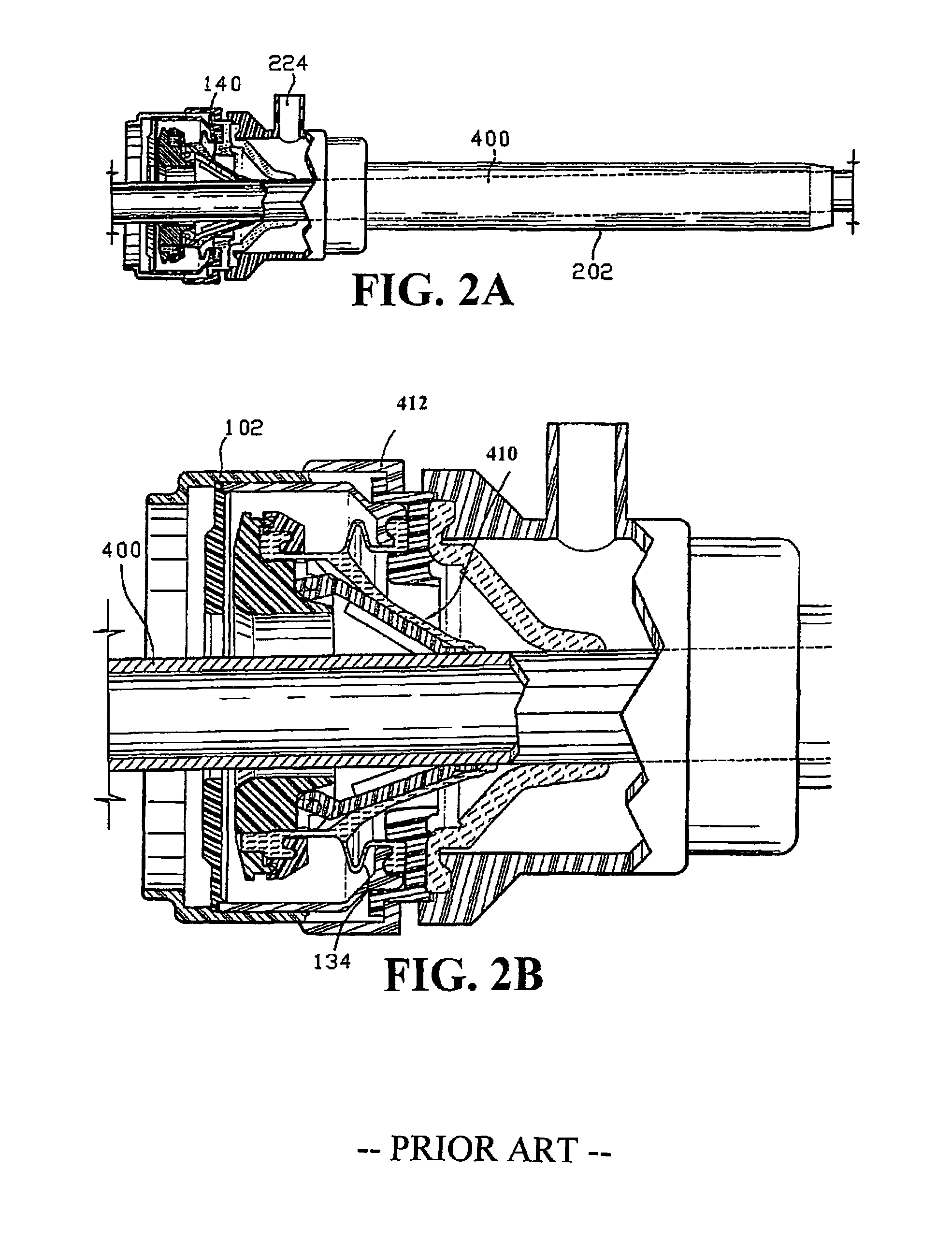
FIG. 2A is a perspective view of a trocar assembly having the seal assembly;
FIG. 2A is a perspective view of a trocar assembly having a seal assembly;
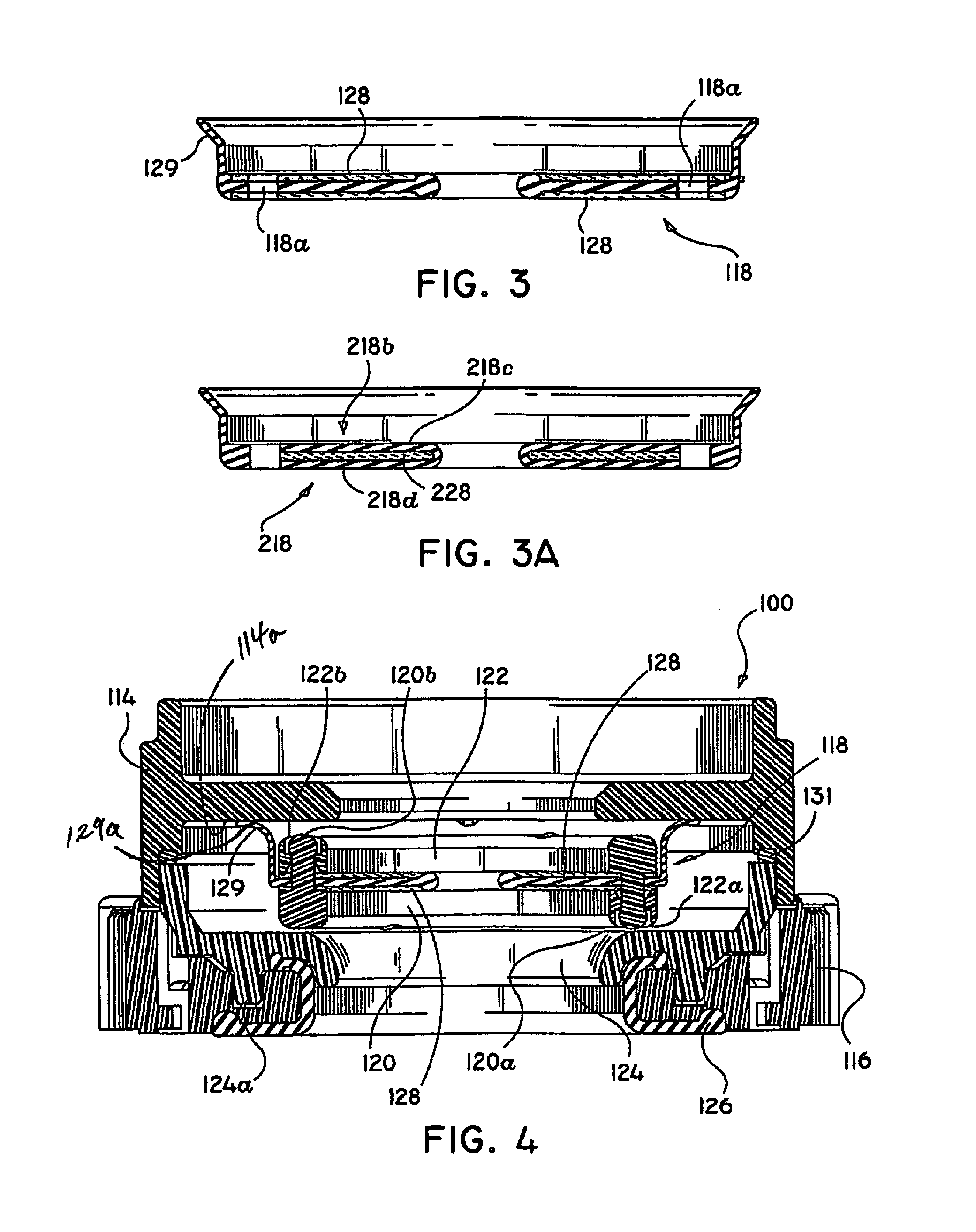
FIG. 3 is a cross-sectional view of a seal member constructed in accordance with the present disclosure;
FIG. 3A is an alternative embodiment of the seal element of FIG. 3;
FIG. 4 is a cross-sectional view of the seal assembly of FIG. 2;
FIG. 5 is a partial cross-sectional view showing the seal body housing taken along section line 5-5 of FIG. 1;
FIG. 6 is an alternative embodiment of a seal assembly constructed in accordance with the present disclosure;
FIG. 7 is further alternative embodiment of a seal assembly constructed in accordance with the present disclosure; and
FIG. 8 is an alternative embodiment of a ring element of the present disclosure.
DETAILED DESCRIPTION OF PREFERRED EMBODIMENTS
Referring now in detail to the drawing figures in which like reference numerals identify similar or identical elements, a seal assembly of the present disclosure is illustrated in FIGS. 1-5, and is designated generally as seal assembly 100.
The presently disclosed seal assembly embodiments contemplate the introduction of various types of surgical instruments adapted for insertion through an elongated trocar assembly. Examples of such instruments include clip appliers, graspers, dissectors, retractors, staplers, laser fibers, photographic devices, endoscopes and laparoscopes, tubes, and the like. Such instruments are collectively referred to herein as "instruments".
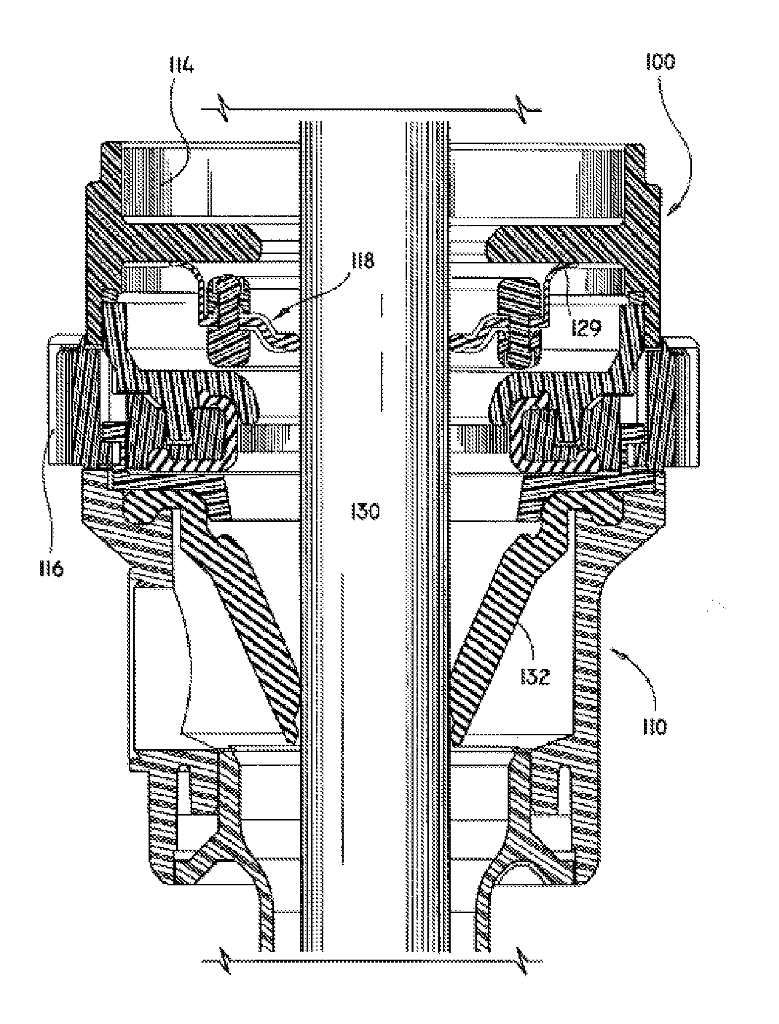
Referring to FIGS. 1 and 2, seal assembly 100 is used in combination with a conventional trocar assembly which includes a cannula assembly 110 and a trocar obturator 112. Examples of trocar assemblies in which the present seal assembly may be utilized are disclosed in U.S. Pat. No. 5,603,702 which issued on Feb. 18, 1997 to Smith et al. and U.S. application Ser. No. 08/546,009 filed Oct. 20, 1995 by Smith et al., the entire contents of each of these disclosures are hereby incorporated by reference. Generally, in FIGS. 2A and 2B, the valve assembly permits limited unencumbered movement of the instrument in a radial direction (relative to the centerline of cannula 202) while still maintaining an adequate seal about the instrument. This is due to the strategic spacing of the inner valve components, i.e., guard mount 106 and seal 110, relative to the valve body, i.e., end cap 102 and seal housing 412, and the bellows structure 134 of the seal 410. In particular, the bellows structure 134 provides sufficient flexibility to permit the valve components to "float" within the valve housing while still preserving the integrity of the seals established about the surgical instrument and within the cannula assembly. Thus, manipulation of the instrument in any direction, either longitudinally or radially, to the extent permitted by the rigid housings and cannula, will not affect the seal, since the resilient material of the seal element and the bellows structure will conform to the movements of the instrument and assume a desired shape necessary to retain sealing contact with the instrument.
Seal assembly 100, either alone or in combination with a seal unit/seal assembly internal to cannula assembly 110 provides a substantial seal between a body cavity of a patient and the outside atmosphere both during and subsequent to insertion of an instrument through the cannula. In this manner, insufflation gases are prevented from escaping through the trocar assembly to the outside environment. Seal assembly 100 is capable of accommodating instruments of varying diameter, e.g., from about 5 mm to about 12 mm, while providing a fluid tight seal with the outer diameter of each instrument. The versatility of the presently disclosed seal assembly facilitates endoscopic, surgery, wherein a variety of instruments having different diameters are often needed during a single surgical procedure.
Seal assembly 100 is preferably detachably mountable to the proximal end of cannula assembly 110. Thus, the surgeon can remove seal assembly 100 from the cannula assembly 110 at any time during the surgical procedure and, similarly, mount the seal assembly 100 to the cannula when desired. In addition, seal assembly 100 may be readily adapted for mounting to conventional cannulas of differing structures. The detachability of seal assembly 100 from cannula assembly 110 facilitates specimen removal through cannula assembly 110.
Referring to FIGS. 3 and 4, seal assembly 100 includes a seal member 118 disposed within a body or housing which is formed by the snap fitting together of end cap 114 and lower housing member 116. Preferably the housing components of seal assembly 100 are formed of a polycarbonate material such as ABS available from the General Electric Company.
A seal support or a two part ring assembly which includes ring members 120 and 122 are snap fitted together on either side of seal member 118. Ring member 120 is disposed adjacent the distally facing surface of seal member 118 and ring member 118. Ring 120 is provided with holes 120a and posts 120b which are alternately disposed around the ring and are aligned with holes 118a on seal member 118. Ring 122 is provided with posts 122a and holes 112b which mate holes 120a and posts 120b of ring member 120, respectively by snap fitting together and 122 are shown having alternating holes and posts, one of the rings could have all holes formed therein while the other ring could have all posts aligned with the holes of the other ring. Additionally, greater or fewer holes and posts may be utilized to secure the two rings together.
A seal clamp 124 is provided within the housing components 114 and 116 which secures an O-ring 131 and lower seal 126 with respect to seal assembly 100. Seal clamp 124 is provided with projecting posts 124a which fit within openings formed on the proximal side of lower housing 116. Seal clamp 124 also serves to secure a proximal flange of a lower seal 126 which is provided at the distal end of lower housing member 116. Lower seal 126 assists in the sealing engagement of seal assembly 100 to cannula assembly 110.
As best shown in FIG. 3, seal member 118 includes fabric 128 which is preferably disposed on both the proximal and distal sides thereof. Fabric 128 may alternatively be disposed on just one of either the proximally facing surface or the distally facing surface. Fabric 128 may be of any suitable fabric, for example, a SPANDEX material containing about 20% LYCRA and about 80% NYLON available from Milliken. A sealing flange 129 (FIG. 4) is formed on the upper outer periphery of seal member 118 and contacts end cap 114 when seal member 118 is disposed within seal assembly 100. In particular, a terminal end 129a of sealing flange 129 is flat against a contacting surface 114a of end cap 114.
In one method of forming seal member 118 with fabric 128 a raw, i.e., uncured polyisoprene plug is first compressed into a flat state, e.g., a flat sheet of polyisoprene. A single layer of fabric is positioned on top of the flattened polyisoprene sheet and compressed into the uncured rubber by any suitable compression process such as, for example, calendering. If it is desired to have fabric on both sides of seal member 118, this process is also accomplished on the other side of the polyisoprene sheet. The fabric polyisoprene composite is die cut into circular slugs having an outer diameter and an inner diameter which forms a central aperture. The slugs are placed in a hot compression mold to cure the polyisoprene. Molding of wing 129 may be simultaneously accomplished.
During the above-described process the bleed-through of the polyisoprene material into and/or through the fabric layers is regulated by the density of the fabric selected. A greater degree of bleed-through of polyisoprene provides greater resistance to fraying of the fabric upon repeated insertion of instruments through the seal. However, too much bleed-through of the polyisoprene through the fabric may affect instrument insertion.
Referring to FIG. 3A, an alternative embodiment of seal member 118 is shown as seal member 218. Seal member 218 is the same as seal member 118 in most aspects except that inner section 218b is formed to have fabric layer 228 enveloped between upper and lower polyisoprene layers 218c and 218d, respectively.
In order to reduce friction between instruments and the seal member, e.g. seal member 118 or seal member 218, as instruments are inserted through seal assembly 100, a coating may be applied to the seal member. One coating which has been found particularly effective is a hydrocyclosiloxane membrane prepared by plasma polymerization process. Such a coating is available from Innerdyne, Inc. of Salt Lake City, Utah, U.S.A., and is disclosed in U.S. Pat. No. 5,463,010 which issued to Hu et al. on Oct. 31, 1995, the entire contents of which are hereby incorporated by reference.
FIG. 5 shows a shaft 130 of a surgical instrument, such as trocar obturator 112 (FIG. 1), inserted through seal assembly 100 and a duck bill valve or "zero" seal valve 132 which prevents the escape of insufflation gases in the absence of an instrument in the trocar assembly. As shown in FIG. 5, seal member 118 provides a seal about the periphery of instrument shaft 130.
Referring to FIG. 6, an alternative embodiment of seal assembly 100 is designated generally as seal assembly 300. Seal assembly 300 is the same as seal assembly 100 except that an inner planar seal member 352 is disposed in the distal end of seal assembly 100 to provide additional sealing capability for instruments having larger diameters. Seal element 352 has an aperture 354 which has a diameter larger than the diameter of aperture 156 of seal member 118.
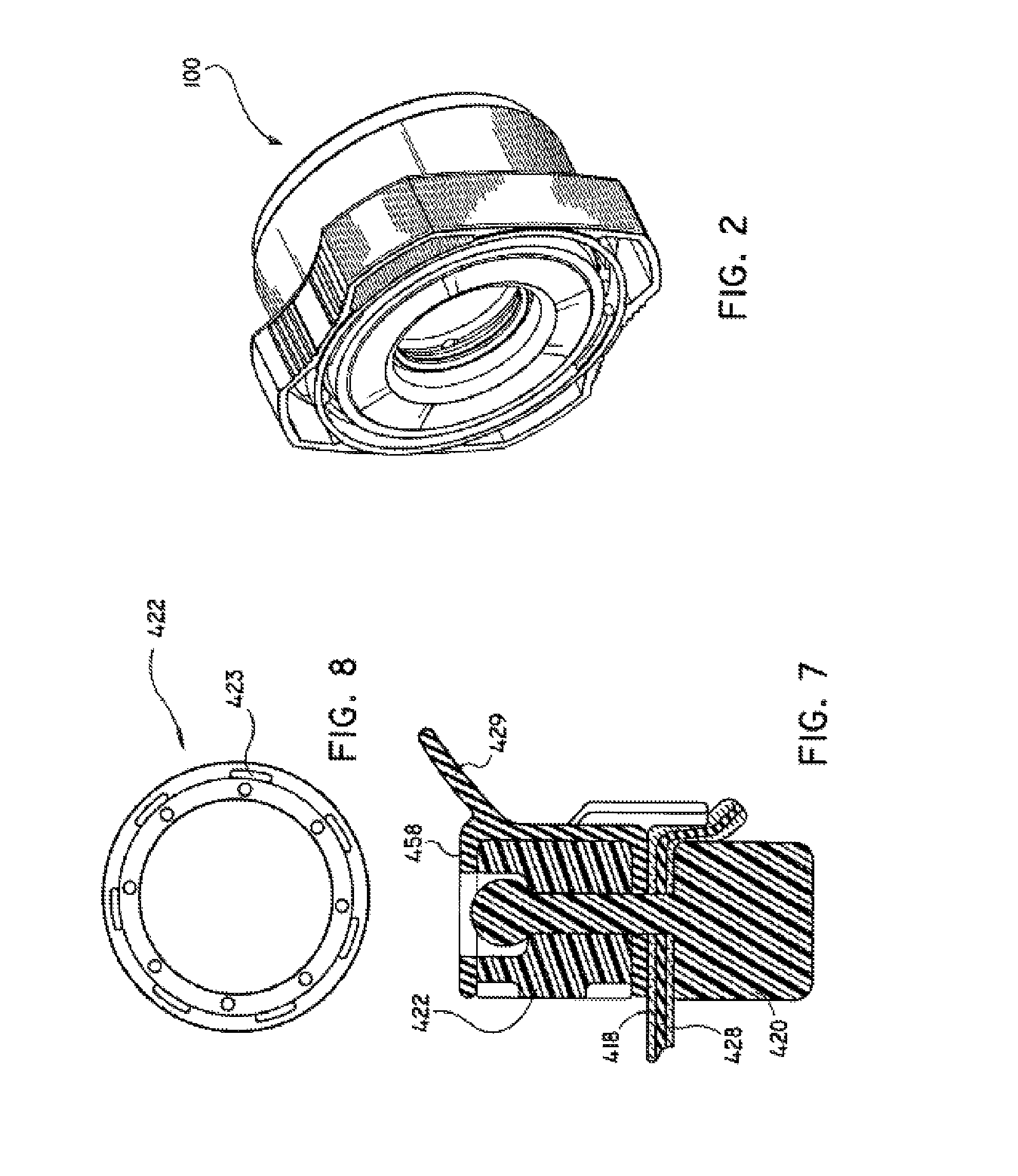
Referring to FIGS. 7 and 8, an alternative feature of the presently disclosed seal assembly is a dampening element such as over-molded coating 458. Coating 458 may be formed over upper ring 422 by the over-molding the ring with material such as polyisoprene so as to envelope part or all of the ring thereby forming a bumper between the ring and the inner surface of upper housing component 114. In this manner, sealing flange 429 may be formed as a separate element from seal member 418, i.e., as part of dampening coating 458. Ring 422 is modified from ring 122 to include peripheral slots 423 which serve to anchor sealing flange 429 as the rubber material forming coating 458 flows through slots 423 prior to curing.
Other dampening element configurations are also contemplated. For example, a pad which is secured to the proximal surface of ring 122 may be provided to dampen the sound created by the impact of the proximal surface of ring 122 with the inner distal facing surface of housing component 114.
It will be understood that various modifications may be made to the embodiments shown herein. Therefore, the above description should not be construed as limiting, but merely as exemplifications of preferred embodiments. Those skilled in the art will envision other modifications within the scope and spirit of the presently disclosed seal assemblies.
* * * * *
D00000
D00001
D00002
D00003
D00004
D00005
D00006
XML
uspto.report is an independent third-party trademark research tool that is not affiliated, endorsed, or sponsored by the United States Patent and Trademark Office (USPTO) or any other governmental organization. The information provided by uspto.report is based on publicly available data at the time of writing and is intended for informational purposes only.
While we strive to provide accurate and up-to-date information, we do not guarantee the accuracy, completeness, reliability, or suitability of the information displayed on this site. The use of this site is at your own risk. Any reliance you place on such information is therefore strictly at your own risk.
All official trademark data, including owner information, should be verified by visiting the official USPTO website at www.uspto.gov. This site is not intended to replace professional legal advice and should not be used as a substitute for consulting with a legal professional who is knowledgeable about trademark law.