System and method for maintaining a consistent temperature gradient across an electronic display
Dunn , et al. Sept
U.S. patent number 10,420,257 [Application Number 15/456,117] was granted by the patent office on 2019-09-17 for system and method for maintaining a consistent temperature gradient across an electronic display. This patent grant is currently assigned to Manufacturing Resources International, Inc.. The grantee listed for this patent is Manufacturing Resources International, Inc.. Invention is credited to William Dunn, Tim Hubbard, Chris Tran.


| United States Patent | 10,420,257 |
| Dunn , et al. | September 17, 2019 |
| **Please see images for: ( Certificate of Correction ) ** |
System and method for maintaining a consistent temperature gradient across an electronic display
Abstract
An electronic display assembly having forced-air cooling. A thermally conductive plate or a thermally conductive backlight surface is located behind an electronic display of the electronic display assembly and within a housing thereof such that a gap is formed between the plate or backlight surface and an adjacent wall of the housing. External cooling air may be caused to flow in a top-to-bottom direction through the gap in order to remove heat from the electronic display that has been conductively transferred to the gap. A plurality of ribs may be placed within the gap and in thermal communication with the electronic display to enhance the conductive transfer of heat from the electronic display.
| Inventors: | Dunn; William (Alpharetta, GA), Tran; Chris (Alpharetta, GA), Hubbard; Tim (Alpharetta, GA) | ||||||||||
|---|---|---|---|---|---|---|---|---|---|---|---|
| Applicant: |
|
||||||||||
| Assignee: | Manufacturing Resources
International, Inc. (Alpharetta, GA) |
||||||||||
| Family ID: | 45526394 | ||||||||||
| Appl. No.: | 15/456,117 | ||||||||||
| Filed: | March 10, 2017 |
Prior Publication Data
| Document Identifier | Publication Date | |
|---|---|---|
| US 20170188490 A1 | Jun 29, 2017 | |
Related U.S. Patent Documents
| Application Number | Filing Date | Patent Number | Issue Date | ||
|---|---|---|---|---|---|
| 14247658 | Apr 8, 2014 | 9594271 | |||
| 12952745 | Apr 8, 2014 | 8693185 | |||
| 12641468 | Feb 18, 2014 | 8654302 | |||
| 12411925 | Oct 7, 2014 | 8854595 | |||
| 12556029 | Feb 12, 2013 | 8373841 | |||
| 12620330 | Sep 25, 2012 | 8274622 | |||
| 12706652 | Jan 22, 2013 | 8358397 | |||
| 12630469 | Jul 30, 2013 | 8497972 | |||
| 12618104 | Nov 13, 2012 | 8310824 | |||
| 12905704 | Jul 8, 2014 | 8773633 | |||
| 12753298 | Jan 8, 2013 | 8351014 | |||
| 61321364 | Apr 6, 2010 | ||||
| 61138736 | Dec 18, 2008 | ||||
| 61039454 | Mar 26, 2008 | ||||
| 61095615 | Sep 9, 2008 | ||||
| 61115333 | Nov 17, 2008 | ||||
| 61152879 | Feb 16, 2009 | ||||
| 61252295 | Oct 16, 2009 | ||||
| Current U.S. Class: | 1/1 |
| Current CPC Class: | H05K 7/20154 (20130101); H05K 5/0017 (20130101); H05K 7/20972 (20130101); G02F 1/0105 (20130101); H05K 7/20136 (20130101); G02F 1/133385 (20130101); F28F 3/02 (20130101); F28F 3/12 (20130101); G02F 2201/36 (20130101) |
| Current International Class: | G02F 1/1333 (20060101); H05K 7/20 (20060101); G02F 1/01 (20060101); H05K 5/00 (20060101); F28F 3/02 (20060101); F28F 3/12 (20060101) |
References Cited [Referenced By]
U.S. Patent Documents
| 4093355 | June 1978 | Kaplit et al. |
| 4593978 | June 1986 | Mourey et al. |
| 4634225 | January 1987 | Haim et al. |
| 4748765 | June 1988 | Martin |
| 4763993 | August 1988 | Vogeley et al. |
| 4921041 | May 1990 | Akachi |
| 4952783 | August 1990 | Aufderheide et al. |
| 4952925 | August 1990 | Haastert |
| 5029982 | July 1991 | Nash |
| 5043979 | August 1991 | Sakurai et al. |
| 5088806 | February 1992 | McCartney et al. |
| 5247374 | September 1993 | Terada |
| 5282114 | January 1994 | Stone |
| 5293930 | March 1994 | Pitasi |
| 5432526 | July 1995 | Hyatt |
| 5535816 | July 1996 | Ishida |
| 5559614 | September 1996 | Urbish et al. |
| 5621614 | April 1997 | O'Neill |
| 5657641 | August 1997 | Cunningham et al. |
| 5748269 | May 1998 | Harris et al. |
| 5765743 | June 1998 | Sakiura et al. |
| 5767489 | June 1998 | Ferrier |
| 5808418 | September 1998 | Pitman et al. |
| 5818010 | October 1998 | McCann |
| 5818694 | October 1998 | Daikoku et al. |
| 5835179 | November 1998 | Yamanaka |
| 5864465 | January 1999 | Liu |
| 5869818 | February 1999 | Kim |
| 5869919 | February 1999 | Sato et al. |
| 5903433 | May 1999 | Gudmundsson |
| 5991153 | November 1999 | Heady |
| 6003015 | December 1999 | Kang et al. |
| 6007205 | December 1999 | Fujimori |
| 6089751 | July 2000 | Conover et al. |
| 6104451 | August 2000 | Matsuoka et al. |
| 6157432 | December 2000 | Helbing |
| 6181070 | January 2001 | Dunn et al. |
| 6191839 | February 2001 | Briley et al. |
| 6198222 | March 2001 | Chang |
| 6211934 | April 2001 | Habing et al. |
| 6215655 | April 2001 | Heady et al. |
| 6351381 | February 2002 | Bilski et al. |
| 6392727 | May 2002 | Larson et al. |
| 6417900 | July 2002 | Shin et al. |
| 6428198 | August 2002 | Saccomanno et al. |
| 6473150 | October 2002 | Takushima et al. |
| 6476883 | November 2002 | Salimes et al. |
| 6493440 | December 2002 | Gromatsky et al. |
| 6504713 | January 2003 | Pandolfi et al. |
| 6535266 | March 2003 | Nemeth et al. |
| 6628355 | September 2003 | Takahara |
| 6701143 | March 2004 | Dukach et al. |
| 6714410 | March 2004 | Wellhofer |
| 6727468 | April 2004 | Nemeth |
| 6742583 | June 2004 | Tikka |
| 6812851 | November 2004 | Dukach et al. |
| 6825828 | November 2004 | Burke et al. |
| 6839104 | January 2005 | Taniguchi et al. |
| 6850209 | February 2005 | Mankins et al. |
| 6885412 | April 2005 | Ohnishi et al. |
| 6886942 | May 2005 | Okada et al. |
| 6891135 | May 2005 | Pala et al. |
| 6909486 | June 2005 | Wang et al. |
| 6943768 | September 2005 | Cavanaugh et al. |
| 6961108 | November 2005 | Wang et al. |
| 7015470 | March 2006 | Faytlin et al. |
| 7059757 | June 2006 | Shimizu |
| 7083285 | August 2006 | Hsu et al. |
| 7157838 | January 2007 | Thielemans et al. |
| 7161803 | January 2007 | Heady |
| 7190587 | March 2007 | Kim et al. |
| 7209349 | April 2007 | Chien et al. |
| 7212403 | May 2007 | Rockenfell |
| 7259964 | August 2007 | Yamamura et al. |
| 7269023 | September 2007 | Nagano |
| 7284874 | October 2007 | Jeong et al. |
| 7452121 | November 2008 | Cho et al. |
| 7457113 | November 2008 | Kumhyr et al. |
| 7480140 | January 2009 | Nara et al. |
| 7535543 | May 2009 | Dewa et al. |
| 7591508 | September 2009 | Chang |
| 7602469 | October 2009 | Shin |
| D608775 | January 2010 | Leung |
| 7667964 | February 2010 | Kang et al. |
| 7682047 | March 2010 | Hsu et al. |
| 7752858 | July 2010 | Johnson et al. |
| 7753567 | July 2010 | Kang et al. |
| 7762707 | July 2010 | Kim et al. |
| 7800706 | September 2010 | Kim et al. |
| 7813124 | October 2010 | Karppanen |
| 7903416 | March 2011 | Chou |
| 7995342 | August 2011 | Nakamichi et al. |
| 8004648 | August 2011 | Dunn |
| 8035968 | October 2011 | Kwon et al. |
| 8081465 | December 2011 | Nishiura |
| 8102173 | January 2012 | Merrow |
| 8142027 | March 2012 | Sakai |
| 8208115 | June 2012 | Dunn |
| 8223311 | July 2012 | Kim et al. |
| 8241573 | August 2012 | Banerjee et al. |
| 8248784 | August 2012 | Nakamichi et al. |
| 8254121 | August 2012 | Lee et al. |
| 8269916 | September 2012 | Ohkawa |
| 8270163 | September 2012 | Nakamichi et al. |
| 8274622 | September 2012 | Dunn |
| 8274789 | September 2012 | Nakamichi et al. |
| 8300203 | October 2012 | Nakamichi et al. |
| 8320119 | November 2012 | Isoshima et al. |
| 8351014 | January 2013 | Dunn |
| 8358397 | January 2013 | Dunn |
| 8369083 | February 2013 | Dunn et al. |
| 8373841 | February 2013 | Dunn |
| 8379182 | February 2013 | Dunn |
| 8400608 | March 2013 | Takahashi et al. |
| 8472174 | June 2013 | Idems et al. |
| 8472191 | June 2013 | Yamamoto et al. |
| 8482695 | July 2013 | Dunn |
| 8497972 | July 2013 | Dunn et al. |
| 8590602 | November 2013 | Fernandez |
| 8649170 | February 2014 | Dunn et al. |
| 8649176 | February 2014 | Okada et al. |
| 8654302 | February 2014 | Dunn et al. |
| 8678603 | March 2014 | Zhang |
| 8693185 | April 2014 | Dunn et al. |
| 8700226 | April 2014 | Schuch et al. |
| 8711321 | April 2014 | Dunn et al. |
| 8749749 | June 2014 | Hubbard |
| 8755021 | June 2014 | Hubbard |
| 8758144 | June 2014 | Williams et al. |
| 8760613 | June 2014 | Dunn |
| 8767165 | July 2014 | Dunn |
| 8773633 | July 2014 | Dunn et al. |
| 8804091 | August 2014 | Dunn et al. |
| 8823916 | September 2014 | Hubbard et al. |
| 8854572 | October 2014 | Dunn |
| 8854595 | October 2014 | Dunn |
| 8879042 | November 2014 | Dunn |
| 8988647 | March 2015 | Hubbard |
| 9030641 | May 2015 | Dunn |
| 9089079 | July 2015 | Dunn |
| 9119325 | August 2015 | Dunn et al. |
| 9119330 | August 2015 | Hubbard et al. |
| 9173322 | October 2015 | Dunn |
| 9173325 | October 2015 | Dunn |
| 9282676 | March 2016 | Diaz |
| 9285108 | March 2016 | Dunn et al. |
| 9313917 | April 2016 | Dunn et al. |
| 9370127 | June 2016 | Dunn |
| 9448569 | September 2016 | Schuch et al. |
| 9451060 | September 2016 | Bowers et al. |
| 9451733 | September 2016 | Dunn et al. |
| 9456525 | September 2016 | Yoon et al. |
| 9470924 | October 2016 | Dunn et al. |
| 9500896 | November 2016 | Dunn et al. |
| 9516485 | December 2016 | Bowers et al. |
| 9549490 | January 2017 | Hubbard |
| 9594271 | March 2017 | Dunn |
| 9613548 | April 2017 | DeMars |
| 9622392 | April 2017 | Bowers et al. |
| 9629287 | April 2017 | Dunn |
| 9648790 | May 2017 | Dunn et al. |
| 9655289 | May 2017 | Dunn et al. |
| 9723765 | August 2017 | DeMars |
| 9894800 | February 2018 | Dunn |
| 2001/0001459 | May 2001 | Savant et al. |
| 2001/0019454 | September 2001 | Tadic-Galeb et al. |
| 2002/0009978 | January 2002 | Dukach et al. |
| 2002/0033919 | March 2002 | Sanelle et al. |
| 2002/0065046 | May 2002 | Mankins et al. |
| 2002/0084891 | July 2002 | Mankins et al. |
| 2002/0101553 | August 2002 | Enomoto et al. |
| 2002/0126248 | September 2002 | Yoshia |
| 2002/0148600 | October 2002 | Bosch et al. |
| 2002/0149714 | October 2002 | Anderson et al. |
| 2002/0154255 | October 2002 | Gromatzky et al. |
| 2002/0164944 | November 2002 | Haglid |
| 2002/0164962 | November 2002 | Mankins et al. |
| 2002/0167637 | November 2002 | Burke et al. |
| 2003/0007109 | January 2003 | Park |
| 2003/0020884 | January 2003 | Okada et al. |
| 2003/0043091 | March 2003 | Takeuchi et al. |
| 2003/0104210 | June 2003 | Azumi et al. |
| 2003/0128511 | July 2003 | Nagashima et al. |
| 2003/0214785 | November 2003 | Perazzo |
| 2004/0012722 | January 2004 | Alvarez |
| 2004/0035558 | February 2004 | Todd et al. |
| 2004/0036834 | February 2004 | Ohnishi et al. |
| 2004/0042174 | March 2004 | Tomioka |
| 2004/0103570 | June 2004 | Ruttenberg |
| 2004/0105159 | June 2004 | Saccomanno et al. |
| 2004/0165139 | August 2004 | Anderson et al. |
| 2004/0223299 | November 2004 | Ghosh |
| 2005/0012039 | January 2005 | Faytlin et al. |
| 2005/0012722 | January 2005 | Chon |
| 2005/0062373 | March 2005 | Kim et al. |
| 2005/0073632 | April 2005 | Dunn et al. |
| 2005/0073639 | April 2005 | Pan |
| 2005/0127796 | June 2005 | Olesen et al. |
| 2005/0134525 | June 2005 | Tanghe et al. |
| 2005/0134526 | June 2005 | Willem et al. |
| 2005/0213950 | September 2005 | Yoshimura |
| 2005/0229630 | October 2005 | Richter et al. |
| 2005/0237714 | October 2005 | Ebermann |
| 2005/0276053 | December 2005 | Nortrup et al. |
| 2005/0286131 | December 2005 | Saxena et al. |
| 2006/0012958 | January 2006 | Tomioka et al. |
| 2006/0018093 | January 2006 | Lai et al. |
| 2006/0034051 | February 2006 | Wang et al. |
| 2006/0056994 | March 2006 | Van Lear et al. |
| 2006/0082271 | April 2006 | Lee |
| 2006/0092348 | May 2006 | Park |
| 2006/0125998 | June 2006 | Dewa et al. |
| 2006/0132699 | June 2006 | Cho |
| 2006/0177587 | August 2006 | Ishizuka |
| 2006/0199514 | September 2006 | Kimura |
| 2006/0209266 | September 2006 | Utsunomiya |
| 2006/0260790 | November 2006 | Theno et al. |
| 2006/0262079 | November 2006 | Seong et al. |
| 2006/0266499 | November 2006 | Choi et al. |
| 2006/0283579 | December 2006 | Ghosh et al. |
| 2007/0019419 | January 2007 | Hafuka et al. |
| 2007/0030879 | February 2007 | Hatta |
| 2007/0047239 | March 2007 | Kang et al. |
| 2007/0065091 | March 2007 | Hinata et al. |
| 2007/0076431 | April 2007 | Atarashi et al. |
| 2007/0081344 | April 2007 | Cappaert et al. |
| 2007/0103863 | May 2007 | Kim |
| 2007/0103866 | May 2007 | Park |
| 2007/0115686 | May 2007 | Tyberghien |
| 2007/0139929 | June 2007 | Yoo et al. |
| 2007/0140671 | June 2007 | Yoshimura |
| 2007/0151274 | July 2007 | Roche et al. |
| 2007/0151664 | July 2007 | Shin |
| 2007/0171353 | July 2007 | Hong |
| 2007/0206158 | September 2007 | Kinoshita et al. |
| 2007/0211205 | September 2007 | Shibata |
| 2007/0212211 | September 2007 | Chiyoda et al. |
| 2007/0217221 | September 2007 | Lee et al. |
| 2007/0237636 | October 2007 | Hsu |
| 2007/0267174 | November 2007 | Kim |
| 2008/0055534 | March 2008 | Kawano |
| 2008/0076342 | March 2008 | Bryant et al. |
| 2008/0099193 | May 2008 | Aksamit et al. |
| 2008/0148609 | June 2008 | Ogoreve |
| 2008/0209934 | September 2008 | Richards |
| 2008/0218446 | September 2008 | Yamanaka |
| 2008/0236005 | October 2008 | Isayev et al. |
| 2008/0267790 | October 2008 | Gaudet et al. |
| 2008/0283234 | November 2008 | Sagi et al. |
| 2008/0285290 | November 2008 | Ohashi et al. |
| 2009/0009047 | January 2009 | Yanagawa et al. |
| 2009/0009729 | January 2009 | Sakai |
| 2009/0059518 | March 2009 | Kakikawa |
| 2009/0065007 | March 2009 | Wilkinson |
| 2009/0086430 | April 2009 | Kang et al. |
| 2009/0120629 | May 2009 | Ashe |
| 2009/0122218 | May 2009 | Oh et al. |
| 2009/0126906 | May 2009 | Dunn |
| 2009/0126907 | May 2009 | Dunn |
| 2009/0126914 | May 2009 | Dunn |
| 2009/0135365 | May 2009 | Dunn |
| 2009/0147170 | June 2009 | Oh et al. |
| 2009/0154096 | June 2009 | Iyengar |
| 2009/0174626 | July 2009 | Isoshima et al. |
| 2009/0231807 | September 2009 | Bouissier |
| 2009/0244472 | October 2009 | Dunn |
| 2009/0279240 | November 2009 | Karppanen |
| 2009/0302727 | December 2009 | Vincent |
| 2009/0306820 | December 2009 | Simmons et al. |
| 2009/0323275 | December 2009 | Rehmann |
| 2010/0060861 | March 2010 | Medin |
| 2010/0079949 | April 2010 | Nakamichi et al. |
| 2011/0019363 | January 2011 | Vahlsing |
| 2011/0085301 | April 2011 | Dunn |
| 2011/0085302 | April 2011 | Nakamichi et al. |
| 2011/0116000 | May 2011 | Dunn |
| 2011/0122162 | May 2011 | Sato et al. |
| 2012/0014063 | January 2012 | Weiss |
| 2012/0188481 | July 2012 | Kang et al. |
| 2015/0366101 | December 2015 | Dunn |
| 2016/0041423 | February 2016 | Dunn |
| 2016/0195254 | July 2016 | Dunn |
| 0N2702363 | May 2005 | CN | |||
| 2702363 | May 2005 | CN | |||
| 1408476 | Apr 2004 | EP | |||
| 1647766 | Apr 2006 | EP | |||
| 1762892 | Mar 2007 | EP | |||
| 1951020 | Jul 2008 | EP | |||
| 2402205 | Dec 2004 | GB | |||
| 402062015 | Mar 1990 | JP | |||
| 402307080 | Dec 1990 | JP | |||
| 3153212 | Jul 1991 | JP | |||
| H062337 | Jan 1994 | JP | |||
| 6082745 | Mar 1994 | JP | |||
| 8115788 | May 1996 | JP | |||
| 8194437 | Jul 1996 | JP | |||
| H8305301 | Nov 1996 | JP | |||
| 8339034 | Dec 1996 | JP | |||
| H09246766 | Sep 1997 | JP | |||
| 11160727 | Jun 1999 | JP | |||
| H11296094 | Oct 1999 | JP | |||
| 2001209126 | Aug 2001 | JP | |||
| 2002158475 | May 2002 | JP | |||
| 2004053749 | Feb 2004 | JP | |||
| 2004286940 | Oct 2004 | JP | |||
| 2005017556 | Jan 2005 | JP | |||
| 2000131682 | May 2005 | JP | |||
| 2005134849 | May 2005 | JP | |||
| 2005265922 | Sep 2005 | JP | |||
| 2006513577 | Apr 2006 | JP | |||
| 2007322718 | May 2006 | JP | |||
| 2006148047 | Jun 2006 | JP | |||
| 2006163217 | Jun 2006 | JP | |||
| 2007003638 | Jan 2007 | JP | |||
| 09307257 | Nov 2007 | JP | |||
| 2007293105 | Nov 2007 | JP | |||
| 2008010361 | Jan 2008 | JP | |||
| 2008292743 | Dec 2008 | JP | |||
| 2010024624 | Feb 2010 | JP | |||
| 2010-102227 | May 2010 | JP | |||
| 20100282109 | Dec 2010 | JP | |||
| 2011-75819 | Apr 2011 | JP | |||
| 2012-133254 | Jul 2012 | JP | |||
| 20000000118 | Jan 2000 | KR | |||
| 20000047899 | Jul 2000 | KR | |||
| 200366674 | Nov 2004 | KR | |||
| 20050033986 | Apr 2005 | KR | |||
| 200401354 | Nov 2005 | KR | |||
| 20060016469 | Feb 2006 | KR | |||
| 100666961 | Jan 2007 | KR | |||
| 1020070070675 | Apr 2007 | KR | |||
| 1020070048294 | Aug 2007 | KR | |||
| WO2005079129 | Aug 2005 | WO | |||
| WO2007116116 | Oct 2007 | WO | |||
| WO2008050660 | May 2008 | WO | |||
| WO2009065125 | May 2009 | WO | |||
| WO2009065125 | May 2009 | WO | |||
| WO2009135308 | Nov 2009 | WO | |||
| WO2010007821 | Feb 2010 | WO | |||
Other References
|
Civiq Smartscapes, LLC V. Manufacturing Resources International, Inc., Memorandum Opinion re claim construction, Sep. 27, 2018, 16 pages. cited by applicant . Civiq Smartscapes, LLC V. Manufacturing Resources International, Inc., Claim Construction order, Oct. 3, 2018, 2 pages. cited by applicant . Anandan, Munismay, Progress of LED backlights for LCDs, 2008, 24 pages. cited by applicant . Itsenclosures, Product Catalog, 2009, 48 pages. cited by applicant . Novitsky, Driving LEDs versus CCFLs for LCD backlighting, Nov. 12, 2007, 6 pages. cited by applicant . Sunbritetv, All Weather Outdoor LCD Television Model 4610HD, 2008, 1 page. cited by applicant . Sunbritetv, Introduces Two New All-Weather Outdoor Televisions InfoComm 2008, 7 pages. cited by applicant . Zeeff, T.M., EMC analysis of an 18'' LCD monitor, 2000, 1 page. cited by applicant . Mentley, David E., State of Flat-Panel Display Technology and Future Trends, Proceedings of the IEEE, Apr. 2002, vol. 90, No. 4, pp. 453-459. cited by applicant . Civiq Smartscapes LLC. V Manufacturing Resources International, Inc., Petition for Inter Partes Review of U.S. Pat. No. 8,854,572 including Declaration of Greg Blonder in Support of Petition, Curriculum Vitae of Greg Blonder and Prosecution History of U.S. Pat. No. 8,854,572, Petition filed Mar. 14, 2018, 427 pages. cited by applicant . Civiq, Invalidity Contentions, Jan. 24, 2018, 51 pages. cited by applicant . Civiq, Invalidity Claim Chart, Appendix I, Mar. 22, 2018, 4 pages. cited by applicant . Civiq, Invalidity Claim Charts, Appendix A-Appendix D, Jan. 24, 2018, 51 pages. cited by applicant . Bureau of Ships Navy Department, Guide Manual of Cooling methods for Electronic Equipment, Mar. 31, 1955, 212 pages. cited by applicant . Wankhede, Evaluation of Cooling Solutions for Outdoor Electronics, Sep. 17-19, 2007, 6 pages. cited by applicant . Scott, Cooling of Electronic Equipment, Apr. 4, 1947, 119 pages. cited by applicant . Sergent, Thermal Management Handbook for Electronic Assemblies, Aug. 14, 1998, 190 pages. cited by applicant . Steinberg, Cooling Techniques for Electronic Equipment First Edition, 1980, 255 pages. cited by applicant . Steinberg, Cooling Techniques for Electronic Equipment Second Edition, 1991, 299 pages. cited by applicant . Yeh, Thermal Management of Microelectronic Equipment, Oct. 15, 2002, 148 pages. cited by applicant . Civiq, Invalidity Claim Charts, Appendix F to H, Mar. 22, 2018, 18 pages. cited by applicant . Yung, Using Metal Core Printed Circuit Board as a Solution for Thermal Management article, 2007, 5 pages. cited by applicant. |
Primary Examiner: Nguyen; Sang V
Attorney, Agent or Firm: Standley Law Group LLP Standley; Jeffrey S. Gayan; Eric M.
Parent Case Text
CROSS-REFERENCE TO RELATED APPLICATIONS
This application is a continuation of U.S. application Ser. No. 14/247,658 filed on Apr. 8, 2014, which is a continuation of U.S. application Ser. No. 12/952,745 filed on Nov. 23, 2010, now U.S. Pat. No. 8,693,185 issued Apr. 8, 2014. U.S. application Ser. No. 12/952,745 is a non-provisional application of U.S. Provisional Application No. 61/321,364 filed Apr. 6, 2010. U.S. application Ser. No. 12/952,745 is also continuation-in-part of U.S. application Ser. No. 12/641,468 filed Dec. 18, 2009, now U.S. Pat. No. 8,654,302 issued Feb. 18, 2014, which is a non-provisional application of U.S. Provisional Application No. 61/138,736 filed Dec. 18, 2008. U.S. application Ser. No. 12/952,745 is also a continuation-in-part of U.S. application Ser. No. 12/411,925 filed Mar. 26, 2009, now U.S. Pat. No. 8,854,595 issued Oct. 7, 2014, which is a non-provisional application of U.S. Provisional Application No. 61/039,454 filed Mar. 26, 2008. U.S. application Ser. No. 12/952,745 is also a continuation-in-part of U.S. application Ser. No. 12/556,029 filed Sep. 9, 2009, now U.S. Pat. No. 8,373,841 issued Feb. 12, 2013, which is a non-provisional application of U.S. Provisional Application No. 61/095,615 filed Sep. 9, 2008. U.S. application Ser. No. 12/952,745 is also a continuation-in-part of U.S. application Ser. No. 12/620,330 filed Nov. 17, 2009, now U.S. Pat. No. 8,274,622 issued Sep. 25, 2012, which is a non-provisional application of U.S. Provisional Application No. 61/115,333 filed Nov. 17, 2008. U.S. application Ser. No. 12/952,745 is also a continuation-in-part of U.S. application Ser. No. 12/706,652 filed Feb. 16, 2010, now U.S. Pat. No. 8,358,397 issued Jan. 22, 2013, which is a non-provisional application of U.S. Provisional Application No. 61/152,879 filed Feb. 16, 2009. U.S. application Ser. No. 12/952,745 is also a continuation-in-part of U.S. application Ser. No. 12/630,469 filed December 3, 2009, now U.S. Pat. No. 8,497,972 issued Jul. 30, 2013. U.S. application Ser. No. 12/952,745 is also a continuation-in-part of U.S. application Ser. No. 12/618,104 filed Nov. 13, 2009, now U.S. Pat. No. 8,310,824 issued Nov. 13, 2012. U.S. application Ser. No. 12/952,745 is also a continuation-in-part of U.S. application Ser. No. 12/905,704 filed Oct. 15, 2010, now U.S. Pat. No. 8,773,633 issued Jul. 8, 2014, which is a non-provisional application of U.S. Provisional Application No. 61/252,295 filed Oct. 16, 2009. U.S. application Ser. No. 12/952,745 is also a continuation-in-part of U.S. application Ser. No. 12/753,298 filed Apr. 2, 2010, now U.S. Pat. No. 8,351,014 issued Jan. 8, 2013. All aforementioned applications are hereby incorporated by reference in their entirety as if fully cited herein.
Claims
What is claimed is:
1. An electronic display assembly with forced-air cooling, comprising: a housing having a front side, a rear side, a top and a bottom; an electronic display located at least partially within the housing so as to be viewable along the front side thereof; a thermally conductive plate located behind the electronic display and in thermal communication therewith, a space between the plate and the rear side of the housing defining a gap; an external air inlet opening located near the top of the housing, the external air inlet opening in flow communication with the gap; an external air exhaust opening located near the bottom of the housing and at a lower elevation than the external air inlet opening, the external air exhaust opening in flow communication with the gap; and at least one fan in flow communication with the gap, the at least one fan being operative to produce an air inlet opening-to-air exhaust opening directed flow of external air through the gap.
2. The electronic display assembly of claim 1, wherein the electronic display is selected from the group consisting of a liquid crystal display (LCD), a light emitting diode (LED) display, an organic light emitting diode (OLED) display, a light emitting polymer (LEP) display, an organic electro-luminescence (OEL) display, and a plasma display.
3. The electronic display assembly of claim 2, wherein the thermally conductive plate is the rear surface of an OLED assembly or the rear surface of a LED backlight assembly for a LCD.
4. The electronic display assembly of claim 1, wherein the thermally conductive plate engages the housing so as to form a gas and contaminant barrier between the electronic display and the gap.
5. The electronic display assembly of claim 1, wherein the at least one fan is located near the external air exhaust opening and is operative to pull external air through the gap.
6. The electronic display assembly of claim 1, wherein the at least one fan is placed near the external air inlet opening and is operative to push external air through the gap.
7. The electronic display assembly of claim 1, further comprising a plurality of thermally conductive ribs located within the gap, the ribs being in thermal communication with the electronic display via contact with the thermally conductive plate.
8. The electronic display assembly of claim 7, wherein the thermally conductive ribs are metallic.
9. The electronic display assembly of claim 7, wherein the ribs are arranged at a higher density near the bottom of the display housing than near the top of the display housing.
10. The electronic display assembly of claim 7, wherein the cross-sectional shape of the ribs is selected from the group consisting of a `Z` cross-section, a `T` cross-section, an I-beam cross-section, a hollow square cross-section, a hollow rectangular cross-section, a solid square cross-section, a solid rectangular cross-section, a honeycomb cross-section, and combinations thereof.
11. A combined conductive and convective method of cooling an electronic display assembly, the electronic display assembly including a housing having a front side, a rear side, a top and a bottom, and an electronic display located within the housing so as to be viewable along the front side thereof, the cooling method comprising: locating a thermally conductive plate behind the electronic display and in thermal communication therewith, such that a gap exists between the plate and the rear side of the housing; providing an external air inlet opening that is located near the top of the housing and is in flow communication with the gap; providing an external air exhaust opening that is located near the bottom of the housing and is in flow communication with the gap, the external air exhaust opening located at a lower elevation than the external air inlet opening; and placing at least one fan in flow communication with the gap, operation of the at least one fan causing external air to flow into the external air inlet opening, through the gap, and out of the air exhaust opening, thereby removing heat from the electronic display that has been conductively transferred into the gap through the thermally conductive plate.
Description
TECHNICAL FIELD
Exemplary embodiments described herein generally relate to cooling systems, and in particular, to cooling systems for electronic displays.
BACKGROUND OF THE ART
Improvements to electronic displays now allow them to be used in outdoor environments for informational, advertising, or entertainment purposes. While displays of the past were primarily designed for operation near room temperature, it is now desirable to have displays which are capable of withstanding large surrounding environmental temperature variations. For example, some displays are capable of operating at temperatures as low as -22 F and as high as 113 F or higher. When surrounding temperatures rise, the cooling of the internal display components can become even more difficult.
Additionally, modern displays have become extremely bright, with some backlights producing 1,000-2,000 nits or more. Sometimes, these illumination levels are necessary because the display is being used outdoors, or in other relatively bright areas where the display illumination must compete with other ambient light. In order to produce this level of brightness, illumination devices (ex. LED, organic LED, light emitting polymer (LEP), organic electro luminescence (OEL), and plasma assemblies) may produce a relatively large amount of heat.
Still further, in some situations radiative heat transfer from the sun through a front display surface can also become a source of heat. In some locations 800-1400 Watts/m.sup.2 or more through such a front display surface is common. Furthermore, the market is demanding larger screen sizes for displays. With increased electronic display screen size and corresponding front display surfaces, more heat will be generated and more heat will be transmitted into the displays.
Given the well-known thermodynamic property that cool air falls and hot air rises, it was previously thought that the best way to cool an electronic display was to ingest the cool air which is found near the bottom of the display. Ingesting the warm air near the top of the display as the cooling air did not seem to make thermodynamic sense. While the air near the bottom of the display is sometimes cooler than the air near the top of the display, it was found that this is not always the case. Especially in applications where the display is mounted on a sidewalk or paved environment, heat was found to emanate from the pavement and cause the air near the bottom of the display to have a higher temperature than the air found at the top. Further, the environment near the bottom of the display was found to contain various contaminants such as dirt, dust, water, leaves, and even garbage/waste materials. These contaminants can have an adverse effect on the display if ingested or clogging up the cooling air intake.
Also, when cooling air was used to cool the rear portion of an electronic display (sometimes an LED backlight or LED display) it was found that the area where the cooling air was ingested was maintained at a cooler temperature than the area where the cooling air was exhausted. Temperature variations across an electronic display may be undesirable as they can alter the optical performance of the electronic display. Some components perform differently when subjected to different ambient temperatures. Thus, with temperature variations across an electronic display there can be visible variations in the image generated by the electronic display.
SUMMARY OF THE EXEMPLARY EMBODIMENTS
An exemplary electronic display may be placed in thermal communication with a plurality of thermally conductive ribs where the ribs are placed in the path of cooling air. The heat from the electronic display is distributed throughout the ribs and removed by the cooling air. It has been discovered that forcing air through the relatively narrow channels defined by the ribs improves the ability to remove heat from the electronic display.
For example, and not by way of limitation, LED arrays are commonly used as the illumination devices for LCD displays. As mentioned above, it has been found that the optical properties of LEDs (and other illumination devices) can vary depending on temperature. Thus, when an LED is exposed to room temperatures, it may output light with a certain luminance, wavelength, and/or color temperature. However, when the same LED is exposed to high temperatures, the luminance, wavelength, color temperature, and other properties can vary. Thus, when a temperature variation occurs across an LED backlight (some areas are at a higher temperature than others) there can be optical inconsistencies across the backlight which can be visible to the observer. By using the embodiments herein, heat buildup can be evenly distributed across the ribs and removed from the display. This can prevent any potential `hot spots` in the backlight which may become visible to the observer because of a change in optical properties of the illumination devices (sometimes LEDs). OLED assemblies are also known to vary performance when temperatures vary. These types of displays can also be adequately cooled with the embodiments herein.
The ribs may provide an isolated chamber from the rest of the display so that ambient air can be ingested and used to cool the ribs. This is beneficial for situations where the display is being used in an outdoor environment and the ingested air may contain contaminants (pollen, dirt, dust, water, smoke, etc.) that would damage the sensitive electronic components of the display. While an exemplary embodiment could accept some contaminants, it may still be desirable to limit the amount of contaminants that could be ingested into the display. Thus, some embodiments ingest cooling air from the top of the display. The air near the top of the display has been found to occasionally contain less contaminants than the air at the bottom of the display. Still further, in some applications where the display is mounted in a paved location, heat can radiate from the paved surface below and cause the air near the top of the display to actually be cooler than the air near the bottom of the display. In these situations it might make thermodynamic sense to ingest air from the top of the display.
When ingesting air from the top, it has been found that as the cooling air travels across the rear portion of the electronic display and accepts heat it increases in temperature. Once the cooling air reaches the bottom of the display, it may have increased in temperature substantially and may no longer provide adequate cooling to the bottom portion of the display. Therefore, some embodiments vary the density of the thermally conductive ribs so that a consistent temperature gradient can be achieved across the electronic display. Because the bottom portion is typically warmer, the ribs may be at a higher density in the bottom portion to account for this variation.
If a backlight is used with the particular display application, a backlight with front and rear sides may be used where the front side contains the illumination devices and the rear side contains a thermally conductive surface for dissipating the heat from the illumination devices. Ideally, there should be a low level of thermal resistance between the front and rear sides of the backlights. An exemplary embodiment that requires a backlight may use a metal core PCB with LEDs on the front side and a metallic surface on the rear side.
The foregoing and other features and advantages will be apparent from the following more detailed description of the particular embodiments of the invention, as illustrated in the accompanying drawings.
BRIEF DESCRIPTION OF THE DRAWINGS
A better understanding of the exemplary embodiments will be obtained from a reading of the following detailed description and the accompanying drawings wherein identical reference characters refer to identical parts and in which:
FIG. 1 is a perspective view of an exemplary embodiment mounted in a paved environment;
FIG. 2 is a rear perspective section view of an exemplary set of thermally-conductive ribs and the air inlet aperture;
FIG. 3 is a front perspective section view of an embodiment for cooling a backlight with thermally-conductive ribs;
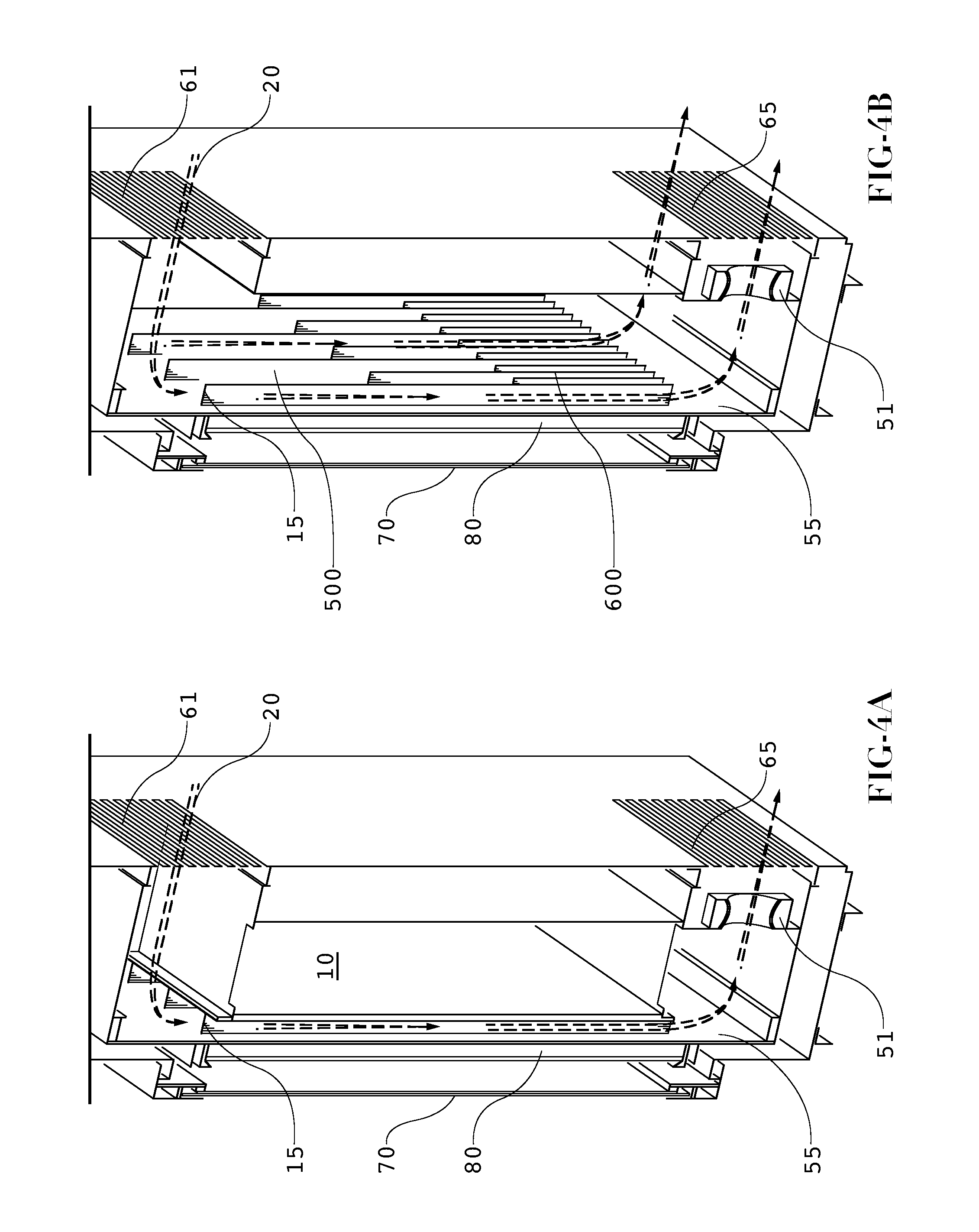
FIG. 4A is a perspective section view of an embodiment showing a path for the cooling air; and
FIG. 4B is a perspective section view of the embodiment of FIG. 4A where the rear plate has been removed so that the variation in rib density can be observed.
DETAILED DESCRIPTION OF EXEMPLARY EMBODIMENTS
FIG. 1 provides a perspective view of an exemplary embodiment of an electronic display 100 mounted on a paved outdoor surface 110. Contaminants 50 may be present on the paved outdoor surface 110 and if the display 100 were to ingest air from the bottom 101, these contaminants 50 would likely be ingested into the display 100. Further, heat 60 is shown radiating from the paved outdoor surface 110. If the display 100 were to ingest air from the bottom 101 it would also likely be warmer than the heat near the top 102 because of the radiating heat 60 from the paved outdoor surface 110.
Thus, the embodiment shown ingests air from the top 102 of the display 100 so that the bulk of the contaminants 50 can be avoided. An opening may be located along the top 102 of the display, preferably along the top horizontal surface of the display 100 housing. Another opening may be located along the bottom 101 horizontal surface. Further, the cooling air 20 can sometimes enter the display 100 at a lower temperature at the top 102 than air which is present near the bottom 101 of the display 100. While this may seem counter-intuitive based on the laws of thermodynamics, acceptable results have been observed.
FIG. 2 provides a sectional view of an exemplary embodiment for thermally-conductive ribs 15, which may be sandwiched in between a front plate 55 (preferably thermally conductive) and a rear plate 10. Preferably, the ribs 15 are in thermal communication with the front plate 55. The front plate 55 may be in thermal communication with the electronic display or electronic image assembly (not shown) so that heat from the electronic display can flow to the front plate 55 and into the ribs 15. Due to the thermally-conductive nature of the ribs 15 and the thermal communication between the front plate 55 and the ribs 15, heat which is present within the electronic display may be removed by the ribs 15. In an exemplary embodiment, a path of cooling air 20 is used to remove the heat which has accumulated on the ribs 15.
In an exemplary embodiment, the plate 10 would provide a gaseous and contaminant barrier between the side containing the ribs 15 and the opposing side (which may house various electronic assemblies). If the plate 10 provides an adequate barrier, ambient air may be ingested as cooling air 20 and the risk of contaminants entering the side of the plate 10 containing the sensitive electronic components may be reduced or eliminated. In a similar exemplary embodiment, the front plate 55 would also provide a gaseous and contaminant barrier between the side containing the ribs 15 and the opposing side which may be in thermal communication with the electronic display. This figure also provides one example of an inlet aperture 25 which accepts the cooling air 20 and directs it along the ribs 15. The cooling air 20 may not only remove heat from the ribs 15 but may also remove it from the front plate 55 and optionally the rear plate 10.
The ribs 15 shown in this embodiment contain a `Z` cross-section, but this is not required. Other embodiments may contain ribs with I-beam cross-sections, hollow square cross-sections, hollow rectangular cross-section, solid rectangular or solid square cross-sections, `T` cross-sections, a honeycomb cross-section, or any combination or mixture of these.
FIG. 3 shows a front perspective section view of an embodiment for cooling a backlight with thermally-conductive ribs 15. The backlight assembly in this embodiment includes a plurality of illumination devices 32 which are mounted on a thermally conductive substrate 30. In an exemplary embodiment, the illumination devices 32 would be LEDs and the thermally conductive substrate 30 would be a PCB and more preferably a metal core PCB. On the surface of the thermally conductive substrate 30 which faces the ribs 15 there may be a thermally conductive front plate 55. In an exemplary embodiment, the thermally conductive front plate 55 would be metallic and more preferably aluminum. It is preferred that the ribs 15 are in thermal communication with the thermally conductive plate 55 and that the thermally conductive plate 55 is in thermal communication with the thermally conductive substrate 30. In some embodiments however, the thermally conductive substrate 30 may comprise traditional PCB materials rather than a metal core PCB or highly thermally conductive materials. It is preferable that there is a low level of thermal resistance between the illumination devices 32 and the ribs 15. Cooling air 20 may again be forced along the ribs 15 in order to remove heat absorbed from the backlight assembly.
As noted above, many illumination devices (especially LEDs and OLEDs) may have performance properties which vary depending on temperature. When `hot spots` are present within a backlight or illumination assembly, these hot spots can result in irregularities in the resulting image which might be visible to the end user. Thus, with the embodiments described herein, the heat which may be generated by the backlight assembly can be distributed (somewhat evenly) throughout the various ribs and thermally-conductive surfaces to remove hot spots and cool the backlight and/or electronic display.
In a further exemplary embodiment, the ribs 15 can also be used to cool additional electronic assemblies by placing them in thermal communication with the rear plate 10. Thus, with the ribs 15 in a central location, the `front` would be towards an intended observer of the display while the `back` would be on the opposite side of an intended observer. Therefore, the front side of the ribs 15 would be in thermal communication with some portion of the electronic display assembly and the rear side of the ribs may be in thermal communication with a rear plate 10 (possibly being thermally-conductive). A single path of cooling air can then be used to cool the interior of the display while the various hot spots can distribute heat throughout the ribs and other thermally conductive surfaces to provide the most efficient cooling.
FIG. 4A is a perspective section view of an embodiment showing a path for the cooling air 20 through the inlet 61 and exhaust 65 apertures. One or more fans 51 may be used to draw the air 20 into the inlet aperture 61 and through the ribs 15. Although shown at the bottom of the display near the exhaust aperture 65, the fans 51 may be placed anywhere within the display so that an adequate flow of cooling air 20 is supplied. Thus, although shown in the figure as `pulling` the cooling air 20 through the ribs 15, other embodiments may `push` the cooling air 20 instead. Still further, some embodiments may `push` and `pull` the cooling air 20. In some embodiments, the air 20 may be air conditioned before it is directed along the ribs 15. In some embodiments, the air 20 may be filtered before it is directed along the ribs 15 in order to remove contaminants. In the embodiment shown, thermally conductive front plate 55 is in thermal communication with the front side of the ribs 15. Preferably, the front plate 55 is also in thermal communication with the electronic display image assembly 80, which could be but is not limited to any of the following: liquid crystal display (LCD), OLED, plasma display assembly, light emitting polymer (LEP) assembly, organic electro luminescence (OEL) assembly, or LED display assembly.
The front plate 55 may be the rear surface of an OLED assembly or the rear surface of an LED backlight assembly for an LCD. A front protective glass 70 is used to protect the electronic display image assembly 80 from damage. Solar loading (radiative heat transfer from the sun through the front protective glass 70) may result in a heat buildup on the electronic display image assembly 80. Thermal communication between the electronic display image assembly 80 and the front plate 55 can provide a means for transferring the solar loading (and any other heat buildup) on the electronic display image assembly 80 to the ribs 15, cooling air 20, and out of the display through the exhaust aperture 65. The front plate 55 can also be the rear surface of any backlight assembly, plasma display assembly, light emitting polymer (LEP) assembly, organic electro luminescence (OEL) assembly, or LED display assembly.
FIG. 4B is a perspective section view of the embodiment of FIG. 4A where the rear plate 10 has been removed so that the optional variation of density in the ribs 15 can be observed. As mentioned above, as cooling air 20 enters the inlet aperture 61 the temperature of the air is relatively low and its ability to cool the upper portion 500 of the display is relatively good. However, as the cooling air 20 travels through the ribs 15, more heat is absorbed by the cooling air 20 and thus raises the temperature of the cooling air 20. Therefore, once cooling air 20 reaches the lower portion 600 of the display, it has risen in temperature and is no longer as effective at removing heat from the ribs 15, electronic image assembly 80, front plate 55, and possibly even the rear plate 10. If heat is not removed at the lower portion 600 in a similar amount as the top portion 500, there may be a temperature variance between the top of the display and the bottom of the display. As discussed above, a variation in temperature across the display can sometimes cause variations in optical properties of various components and a resulting variation of the image.
To counteract this phenomenon, in some embodiments the density of the ribs 15 may optionally be higher in the lower portion 600 than in the upper portion 500 to account for the reduction in heat transfer efficiency due to the higher temperature of the cooling air 20. By providing an increased amount of surface area for the cooling air 20 to contact, heat can be removed from the lower portion 600 (where the cooling air is relatively warm) in a similar amount as the heat removed from the upper portion 500 (where the cooling air 20 is relatively cool). This optional technique can help to balance the temperature across the front plate 55 and thus the electronic image assembly 80 to ensure that the image remains consistent across the display.
It should be noted that although the inlet 61 and exhaust 65 apertures are shown in a vertical orientation on the rear wall (opposite the viewable surface) of the display housing, they can also be placed on the sides of the housing. Alternatively, the inlet aperture 61 may be on the top horizontal surface of the display housing while the exhaust aperture 65 is on the bottom horizontal surface of the display housing.
Although some of the figures herein may show displays which are oriented in a portrait fashion, any orientation can be used with the embodiments described herein. Thus, landscape or widescreen orientations can also be used as well as any type of square orientation.
In some embodiments, the display may not be mounted on a paved surface (or some other object/surface that is radiating heat). In these embodiments, it may be desirable to ingest air from the bottom of the display because this air might be cooler than the air at the top of the display. In this type of design, the variation in rib density may still be used to account for the warming of the cooling air as it travels up the display and exhausts out the top. Here, the top of the display will likely be warmer than the bottom and providing a higher density of ribs near the top of the display can help to balance this thermal irregularity to ensure a consistent image production.
The cooling system may run continuously. However, if desired, temperature sensing devices (not shown) may be incorporated within the electronic display to detect when temperatures have reached a predetermined threshold value. In such a case, the various cooling fans may be selectively engaged when the temperature in the display reaches a predetermined value. Predetermined thresholds may be selected and the system may be configured to advantageously keep the display within an acceptable temperature range. Typical thermostat assemblies can be used to accomplish this task. Thermocouples may be used as the temperature sensing devices.
It is to be understood that the spirit and scope of the disclosed embodiments provides for the cooling of many types of displays. By way of example and not by way of limitation, embodiments may be used in conjunction with any of the following: LCD (all types), light emitting diode (LED), organic light emitting diode (OLED), field emitting display (FED), light emitting polymer (LEP), organic electro luminescence (OEL), and plasma displays. Furthermore, embodiments may be used with displays of other types including those not yet discovered. In particular, it is contemplated that the system may be well suited for use with full color, flat panel OLED displays. Exemplary embodiments may also utilize large (55 inches or more) LED backlit, high definition liquid crystal displays (LCD). While the embodiments described herein are well suited for outdoor environments, they may also be appropriate for indoor applications (e.g., factory/industrial environments, spas, locker rooms) where thermal stability of the display may be at risk.
Having shown and described various exemplary embodiments, those skilled in the art will realize that many variations and modifications may be made to affect the described embodiments and still be within the scope of the included claims. Additionally, many of the elements indicated above may be altered or replaced by different elements which will provide the same result and fall within the spirit of the claimed invention.
* * * * *
D00000
D00001
D00002
D00003
D00004
XML
uspto.report is an independent third-party trademark research tool that is not affiliated, endorsed, or sponsored by the United States Patent and Trademark Office (USPTO) or any other governmental organization. The information provided by uspto.report is based on publicly available data at the time of writing and is intended for informational purposes only.
While we strive to provide accurate and up-to-date information, we do not guarantee the accuracy, completeness, reliability, or suitability of the information displayed on this site. The use of this site is at your own risk. Any reliance you place on such information is therefore strictly at your own risk.
All official trademark data, including owner information, should be verified by visiting the official USPTO website at www.uspto.gov. This site is not intended to replace professional legal advice and should not be used as a substitute for consulting with a legal professional who is knowledgeable about trademark law.