Smart cart
Racenet , et al. Sept
U.S. patent number 10,418,831 [Application Number 15/851,885] was granted by the patent office on 2019-09-17 for smart cart. This patent grant is currently assigned to Covidien LP. The grantee listed for this patent is Covidien LP. Invention is credited to Francesco Alfieri, Danyel Racenet, David Racenet, Parag Sapre.


View All Diagrams
| United States Patent | 10,418,831 |
| Racenet , et al. | September 17, 2019 |
Smart cart
Abstract
An interactive surgical device storage and supply cart is provided and includes a top storage assembly having multiple storage containers for various size product packages, a bottom storage assembly having drawers to retain larger packages of sterilized devices and an intermediate shelf having storage trays for frequently used items. One or more batter chargers are provided on the cart to supply fully charged batteries. A docking station is provided on the cart to receive computers for inventory management and display instructional material. The docking station also can receive communication devices for consultation with outside sources in real time. Additionally, a power strip is provided to power the battery charger (s) and docking station as well as other auxiliary, powered devices and instruments.
| Inventors: | Racenet; David (Killingworth, CT), Racenet; Danyel (Killingworth, CT), Sapre; Parag (Yardley, PA), Alfieri; Francesco (Lincoln, RI) | ||||||||||
|---|---|---|---|---|---|---|---|---|---|---|---|
| Applicant: |
|
||||||||||
| Assignee: | Covidien LP (Mansfield,
MA) |
||||||||||
| Family ID: | 49724990 | ||||||||||
| Appl. No.: | 15/851,885 | ||||||||||
| Filed: | December 22, 2017 |
Prior Publication Data
| Document Identifier | Publication Date | |
|---|---|---|
| US 20180123365 A1 | May 3, 2018 | |
Related U.S. Patent Documents
| Application Number | Filing Date | Patent Number | Issue Date | ||
|---|---|---|---|---|---|
| 14064388 | Oct 28, 2013 | 9887562 | |||
| 61732640 | Dec 3, 2012 | ||||
| Current U.S. Class: | 1/1 |
| Current CPC Class: | A61B 50/18 (20160201); A61B 50/13 (20160201); H02J 7/0042 (20130101); A61B 50/10 (20160201); A61B 2050/105 (20160201); F04C 2270/0421 (20130101); A61B 2050/185 (20160201) |
| Current International Class: | H02J 7/00 (20060101); A61B 50/18 (20160101); A61B 50/10 (20160101); A61B 50/13 (20160101) |
| Field of Search: | ;320/107 ;312/196,209,249.8,249.11-249.13 |
References Cited [Referenced By]
U.S. Patent Documents
| 1944394 | January 1934 | Bales |
| 3168954 | February 1965 | Von Herrmann |
| 3995674 | December 1976 | Crawford |
| 4120549 | October 1978 | Bureau |
| 4373761 | February 1983 | Hansberry, Jr. |
| 5011240 | April 1991 | Kelley et al. |
| 5013103 | May 1991 | Addison |
| 5016948 | May 1991 | Welch et al. |
| 5399007 | March 1995 | Marconet |
| 5423651 | June 1995 | Dinvemo |
| 5518310 | May 1996 | Ellman et al. |
| 5536084 | July 1996 | Curtis et al. |
| 5702115 | December 1997 | Pool |
| 6022088 | February 2000 | Metzler |
| 6053587 | April 2000 | Boerder |
| 6086073 | July 2000 | Tisbo et al. |
| 6116461 | September 2000 | Broadfield |
| 6152048 | November 2000 | Vander Park |
| 6315308 | November 2001 | Konopka |
| 6339732 | January 2002 | Phoon et al. |
| 6626445 | September 2003 | Murphy et al. |
| 6663202 | December 2003 | Spann |
| 6746091 | June 2004 | Friar et al. |
| 6831225 | December 2004 | Chandler |
| 6876902 | April 2005 | Nikolich |
| 6976744 | December 2005 | Hay et al. |
| 7009840 | March 2006 | Clark et al. |
| 7156475 | January 2007 | Gloger, Jr. |
| 7581708 | September 2009 | Newkirk |
| 7665811 | February 2010 | Johanning |
| 7800914 | September 2010 | Dully |
| 7806376 | October 2010 | Song et al. |
| 7809470 | October 2010 | Shoenfeld |
| 8075071 | December 2011 | Whittall |
| 8084992 | December 2011 | Scheffy et al. |
| 8106746 | January 2012 | Maltseff et al. |
| 8109527 | February 2012 | Bustle et al. |
| 8157337 | April 2012 | Manalang et al. |
| 8210548 | July 2012 | Agyemang |
| 8215650 | July 2012 | Arceta et al. |
| 8258973 | September 2012 | Newkirk |
| 8286977 | October 2012 | Butler et al. |
| 8287816 | October 2012 | Kral |
| 8295940 | October 2012 | Sherman |
| 8482252 | July 2013 | Byrne |
| 8696075 | April 2014 | Rios |
| 9887562 | February 2018 | Racenet |
| 2002/0013640 | January 2002 | Phoon et al. |
| 2003/0201697 | October 2003 | Richardson |
| 2005/0178298 | August 2005 | Rossini |
| 2005/0236940 | October 2005 | Rackoff |
| 2006/0219718 | October 2006 | Finnestad |
| 2007/0018433 | January 2007 | Sinnamon et al. |
| 2007/0055116 | March 2007 | Clark et al. |
| 2007/0295627 | December 2007 | Hsieh |
| 2008/0164792 | July 2008 | Goldberg et al. |
| 2008/0203861 | August 2008 | Wingate |
| 2008/0265728 | October 2008 | Collins et al. |
| 2008/0303389 | December 2008 | Petrovich |
| 2008/0316045 | December 2008 | Sriharto et al. |
| 2009/0261992 | October 2009 | Song |
| 2009/0267772 | October 2009 | Dehnadi |
| 2010/0213679 | August 2010 | Smith et al. |
| 2010/0228392 | September 2010 | Braun |
| 2010/0264738 | October 2010 | Murtha et al. |
| 2010/0295430 | November 2010 | Cheng |
| 2010/0312039 | December 2010 | Quirico et al. |
| 2011/0108605 | May 2011 | Sapienza |
| 2011/0134601 | June 2011 | Sa |
| 2011/0172815 | July 2011 | Kim |
| 2012/0087074 | April 2012 | Chen |
| 2012/0180789 | July 2012 | Tobia et al. |
| 1899211 | Jan 2007 | CN | |||
| 102088883 | Jun 2011 | CN | |||
| 102481050 | May 2012 | CN | |||
| 63-102181 | Jul 1988 | JP | |||
| 05-146474 | Jun 1993 | JP | |||
| 2008-048786 | Mar 2008 | JP | |||
| 2011-218154 | Nov 2011 | JP | |||
| 2006074473 | Jul 2006 | WO | |||
| 2007/077609 | Jul 2007 | WO | |||
Other References
|
Chinese Office Action dated Nov. 18, 2016 in corresponding Chinese Patent Appln. No. 2013106421052. cited by applicant . European Search Report EP13195238.4 dated Feb. 24, 2017. cited by applicant . Japanese Office Action dated Jul. 26, 2017 issued in corresponding JP Application No. 2013-248841. cited by applicant . Chinese Office Action dated May 5, 2017 issued in corresponding Chinese Application No. 2013106421052. cited by applicant . Chinese Office Action dated Sep. 21, 2017 issued in corresponding Chinese Application No. 2013106421052. cited by applicant . Australian Examination Report dated Oct. 12, 2017 issued in corresponding Australian Application No. 2013257438. cited by applicant. |
Primary Examiner: Roersma; Andrew M
Parent Case Text
CROSS-REFERENCE TO RELATED APPLICATIONS
This application is a continuation of U.S. patent application Ser. No. 14/064,388 filed Oct. 28, 2013, which claims the benefit of and priority to U.S. Provisional Patent Application No. 61/732,640, filed Dec. 3, 2012, the entire disclosure of which is incorporated by reference herein.
Claims
The invention claimed is:
1. A surgical device storage cart comprising: a top storage assembly having at least two storage containers storing first components of surgical devices, the storage containers having pivotal face plates for revealing the storage containers, the first components being disposable loading units; a bottom storage assembly having at least one storage drawer storing second components of surgical devices; a shelf intermediate the top storage assembly and the bottom storage assembly, the shelf affixed to the bottom storage assembly and defining a central opening therethrough, the top storage assembly including a pair of mounting plates extending through the central opening of the shelf and secured to an inside edge of the bottom storage assembly, the shelf extending around the top storage assembly such that an outer perimeter of the top storage assembly is spaced inwardly of an outer perimeter of the shelf, a front side of the shelf including at least one storage tray defined therein; a battery charging station positioned on the shelf; and an electronic device docking station positioned on the top storage assembly.
2. The storage cart as recited in claim 1, wherein the top storage assembly includes a power strip for supplying power to the battery charging station and the electronic device docking station.
3. The storage cart as recited in claim 2, wherein the at least two storage containers are of differing sizes.
4. The storage cart as recited in claim 2, wherein the top storage assembly has a domed cover to prevent use of the domed cover as a placement surface.
5. The storage cart as recited in claim 2, wherein the top storage assembly has a document holder.
6. The storage cart as recited in claim 2, wherein the top storage assembly has at least one lock cable to secure docking station contents.
7. The storage cart as recited in claim 2, wherein the bottom storage assembly includes a rear access panel.
8. The storage cart as recited in claim 2, wherein the bottom storage assembly includes at least one window to view contents of the at least one storage drawer.
9. The storage cart as recited in claim 2, wherein the bottom storage assembly includes a wheel assembly to facilitate moving the storage cart.
10. The storage cart as recited in claim 2, wherein the top storage assembly includes a removable back panel.
11. The storage cart as recited in claim 10, wherein the top storage assembly includes an internal divider disposed between the at least two storage containers and the removable back panel.
12. The storage cart as recited in claim 11, wherein the power strip is disposed between the removable back panel and the internal divider.
13. The storage cart as recited in claim 11, wherein the power strip is mounted on a shelf disposed between the removable back panel and the internal divider.
14. The storage cart as recited in claim 1, wherein the face plates of the storage containers further have card holders.
15. The storage cart as recited in claim 1, wherein the electronic device docking station is positioned on an outer surface of the top storage assembly.
16. The storage cart as recited in claim 1, wherein a back side of the shelf includes at least one storage tray defined therein.
17. The storage cart as recited in claim 1, wherein the battery charging station is positioned on a first side of the shelf.
18. The storage cart as recited in claim 17, wherein a second side of the shelf includes an item tray.
Description
BACKGROUND
1. Technical Field
The present disclosure relates to a storage cart for surgical stapling products. More particularly, the present disclosure relates to an interactive storage and supply cart having electrical power and mounting capabilities for supporting communications devices, tablet type computers, recharging units and/or power sources for other electrically operated devices.
2. Background of Related Art
During many surgical procedures it is often necessary to employ multiple surgical instruments to properly perform the procedure. Many of these surgical instruments are modular and may include reloadable or disposable components specific to each instrument. This requires a management strategy to keep the surgical instruments and their related components separate to avoid confusion during surgery and avoid wasting time searching for correct instruments and associated components. Maintaining an accurate inventory of what is currently on hand may also become a problem.
Many modern surgical instruments now incorporate powered features that require rechargeable battery packs. Multiple battery packs and associated charges are required to be maintained in the operating room to avoid being faced with a depleted or faulty battery pack during an operation. Multiple chargers placed around the operating room may cause confusion leading to extended operation time and cause danger of tripping over multiple power cords.
More complex surgical procedures often require consultation with outside sources to obtain real time information about dealing with complications that may occur during the surgical procedure.
Therefore, it is desirable to provide a surgical device storage and supply cart capable of maintaining and organizing multiple surgical instruments and associated components. It is further desirable to provide a surgical device storage and supply cart having battery charging capabilities to ensure that fully operational battery packs are readily and safely available to the operating staff. It is still further desirable to provide a surgical device storage and supply cart having a docking station for receipt of computers for inventory management and instructional material or communication devices such as iPod.TM.'s or iPad.TM.'s to provide real time consultation with outside sources such as other surgeons or similar experts.
SUMMARY
There is disclosed a storage cart for storing, displaying and supplying surgical instruments and associated attachments. The storage cart generally includes a top storage assembly having at least two storage containers and a bottom storage assembly having at least one storage drawer. A shelf is positioned intermediate the top storage assembly and the bottom storage assembly and is affixed to the bottom storage assembly. A battery charging station is positioned on the shelf and may include a battery charger for receiving and charging a rechargeable battery and a battery charger holder to support the battery charger on the shelf. An electronic device docking station is positioned on the top storage assembly and is provided to receive electronic devices for tracking the contents of the cart as well as displaying product or surgical procedure information and providing real time communication with outside sources.
The top storage assembly includes a power strip for supplying power to the battery charging station and the electronic device docking station. In one embodiment, the at least two storage containers are of differing sizes. Multiple rows of differing size storage containers are provided to accommodate differing product package sizes. In a specific embodiment, the top storage assembly has a domed cover to prevent its use as a placement surface. This is to discourage placement of items on the top storage assembly and prevent those items from falling off the cart. The top storage assembly also has one or more document holders to support product and patient information and charts. In one embodiment, the top storage assembly has at least one cable lock strap to secure the docking station contents.
The shelf, positioned intermediate the top storage assembly and the bottom storage assembly, includes at least one storage tray for frequently used item and to collect personal items not previously removed prior to surgery.
The lower storage assembly includes a rear access panel to facilitate access to the at least one drawer for restocking. The lower storage assembly also includes at least one window to view the contents of the at least one storage drawer. The lower storage assembly further includes a wheel assembly to facilitate moving the storage cart. The wheel assembly may include one or more locking wheels or castors to secure the storage cart in place.
There is also disclosed a surgical device storage cart including a top storage assembly having a storage container and a bottom storage assembly having a storage drawer. A shelf is positioned intermediate the top storage assembly and the bottom storage assembly and includes at least one battery charger being positioned on the shelf. In one embodiment, at least one battery charger is positioned on a side of the shelf.
In an alternate embodiment, the at least one battery charger includes a first and a second battery charger, the first and second battery chargers positioned on opposite corners of the front of the shelf.
The storage cart further includes an electronic device docking station positioned on the shelf. The storage cart still further includes a power strip in electrical communication with the at least one battery charger and the electronic device docking station to provide power to the battery charger and docking station as well as other powered surgical devices.
There is still further disclosed a surgical device storage cart including a top storage assembly having a storage container, a bottom storage assembly having a storage drawer and a power strip positioned within the top storage assembly. In one embodiment, a battery charger is positioned on the top storage assembly. An electronic device docking station is also positioned on the top storage assembly. In a specific embodiment, the top storage assembly has a domed cover and the battery charger is mounted on the domed cover. The storage cart includes at least one document holder positioned on the top storage assembly.
DESCRIPTION OF THE DRAWINGS
Various embodiments of the presently disclosed interactive surgical product storage, supply and display carts or "smart carts" are disclosed herein with reference to the drawings, wherein:
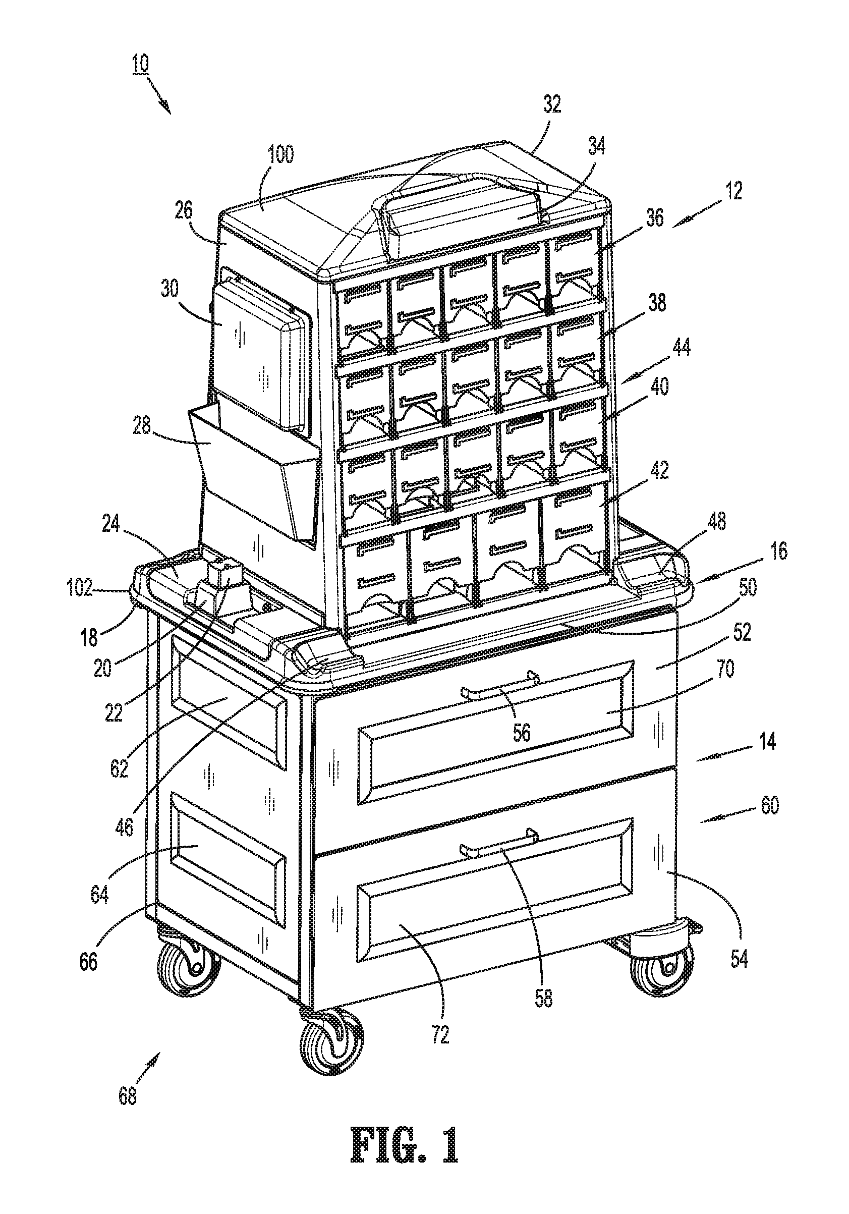
FIG. 1 is a perspective view of one embodiment of a smart cart for use in a surgical operating room;
FIG. 2 is another perspective view of the smart cart;
FIG. 3 is a front plan view of the smart cart;
FIG. 4 is a side plan view of the smart cart;
FIG. 5 is a rear plan view of the smart cart;
FIG. 6 is an opposite side plan view of the smart cart;
FIG. 7 is a top plan view of the smart cart;
FIG. 8 is a bottom plan view of the smart cart;
FIG. 9 is a perspective view of the smart cart with top and bottom storage assemblies separated;
FIG. 10 is a perspective view, with parts separated, of the bottom storage assembly;
FIG. 11 is a perspective view, with parts separated, of the top storage assembly;
FIG. 12 is a further perspective view, with parts separated, of the top storage assembly;
FIG. 13 is a perspective view, with back panel removed, of the top storage assembly revealing a power strip;
FIG. 14 is rear plan view of an alternate embodiment of a smart cart;
FIG. 15 is a top plan view of the smart cart of FIG. 14;
FIG. 16 is a top plan view of an alternate embodiment of an intermediate shelf portion for use with the disclosed smart carts; and
FIG. 17 is a perspective view of a further alternate embodiment of a smart cart.
DETAILED DESCRIPTION OF EMBODIMENTS
Embodiments of the presently disclosed product storage, supply and display carts or "smart carts" will now be described in detail with reference to the drawings wherein like numerals designate identical or corresponding elements in each of the several views. As is common in the art, the term `proximal" refers to that part or component closer to the user or operator, i.e. nurse, surgeon or physician, while the term "distal" refers to that part or component further away from the user.
Referring to FIGS. 1-13, and initially to FIGS. 1-8, there is illustrated one embodiment of an interactive surgical instrument storage, display and supply cart or smart cart 10 for use in a surgical operating room. While not specifically shown, smart cart 10 is provided to store, display and supply ENDO GIA.TM., TRI-STAPLE.TM. and iDRIVE.TM. Surgical stapling products, including instruments and reloading components to surgeons and their assistants in the operating room. Additionally, smart cart 10 provides capabilities for supporting and powering computer and display devices such as, for example, iPad.TM.'s, iPod.TM.'s, etc. as well as charging and supplying fully charged iDrive.TM. Ultra batteries for use with iDrive.TM. surgical instruments. The smart cart 10 typically does not have to be sterile and may be kept in the central core. In the event the smart cart 10 is moved outside the central core a drape (not shown) is provided to cover the cart.
Referring to FIG. 1, smart cart 10 generally includes a top storage assembly 12, a bottom storage assembly 14 and an intermediate shelf or shelf portion 16 positioned between top storage assembly 12 and bottom storage assembly 14. A first side edge 18 of shelf portion 16 contains a removable battery charger 20 for recharging and supplying fully charged battery packs 22. Battery charger 20 may be mounted directly to first side edge 18 of shelf portion 16 or may be positioned in a removable charger holder 24 positioned on first side edge 18. Use of a removable charger holder 24 allows the users to pre-configure smart cart 10 based on the specific powered surgical devices to be used.
With reference to FIGS. 1, 3 and 6, a first side panel 26 of top storage assembly 12 is provided with a document holder 28 which can be used for various purposes, such as, for example, instrument inventory and instructions, patient records, etc. Document holder 28 may also be used to retain electronic device and communication instructions and relevant contact phone/email/texting numbers and addresses. First side panel 26 of top storage assembly 12 is also provided with an electronic device mount or docking station 30 which allows the users to connect and view various tablet type computers, access electronic communication via cellular, Wi Fi and/or Bluetooth devices and view display devices. This allows the surgeon to view surgical product and procedure information and/or consult with external sources in real time. Top storage assembly additionally includes a top cover 32 which is provided with an information retaining cap 34. Cap 34 is provided to display specific patient charts or other documents for immediate viewing.
Referring to FIGS. 1 and 3, top storage assembly 12 is more specifically provided to store and display various surgical stapling reloading components (see FIG. 12). Multiple rows of various size storage containers 38, 40, 42 and 44 are provided in a front side 44 of top storage assembly 12 to retain, identify and/or display the components as described in more detail hereinbelow.
A pair of personal effects storage trays 46 and 48 are provided on a front side 50 of shelf portion 16 to retain patient and provider items not previously removed prior to surgery.
With continued reference to FIGS. 1 and 3, bottom storage assembly 14 includes upper and lower drawers 52 and 54, having respective handles 56 and 58, in a front side 60 of bottom storage assembly 14. Upper and lower drawers 52 and 54 are provided to retain various surgical instruments. Upper and lower viewing windows 62 and 64 are provided in a first side 66 of bottom storage assembly 14 to facilitate viewing the contents of upper and lower drawers 52 and 54. In order to manipulate storage cart 10 within the operating room, bottom storage assembly 14 is provided with a wheel assembly 68, described in more detail hereinbelow. Upper and lower drawers 52 and 54 are provided with front plates 70 and 72 which may be transparent to view the contents or may be used to support labels or other indicia describing the contents of upper and lower drawers 52 and 54.
Referring now to FIGS. 2 and 4, a second side panel 74 of top storage assembly 12 is also provided with a document holder or sleeve 76 for retention of patient records, etc. Top storage assembly 12 additionally includes a removable back panel 78.
Bottom storage assembly 14 includes a frame 80. A second side 82 of bottom storage assembly 14 also includes viewing windows 84 and 86 to view the contents of bottom storage assembly 14.
Referring to FIGS. 2 and 5, a back side 88 of bottom storage assembly 14 is provided with a removable door panel 90 to facilitate restocking upper and lower drawers 52 and 54 (FIG. 1). Removable door panel 90 includes viewing windows 92 and 94 for viewing the contents of upper and lower drawers 52 and 54, respectively. Lock handles 96 and 98 are provided on door panel 90 and engage frame 80 to secure door panel 90 to frame 80.
With reference to FIGS. 1-6, top cap 32 has a domed outer surface 100 to prevent its use as a tray or surface upon which items may be inadvertently placed and knocked or fall off. In order to prevent damage to smart cart 10, shelf portion 16 includes a flexible, polymeric or rubber peripheral edge or bumper 102.
Referring now to FIGS. 2 and 7, shelf portion 16 includes a second side edge 104 having an items tray 106 for receipt of various items frequently used during the surgical procedure. A back side 108 of shelf portion 16 is also provided with a pair of personal effects pockets or trays 110 and 112 similar to trays 46 and 48 in front side 50 of shelf portion 16.
Referring for the moment to FIG. 8, it can be seen that bottom storage assembly 14 includes a floor panel 114 on frame 80. Additionally, wheel assembly 68 includes a pair of front swiveling wheels 116 and 118 and a pair of rear locking wheels 120 and 122.
Referring now to FIGS. 9-13, the construction features of smart cart 10 will now be described. Referring initially to FIG. 9, a fully assembled top storage assembly 12 and fully assembled bottom storage assembly 14 may be provided separately so that the components can be interchanged depending on use. Shelf portion 16 is provided with bottom storage assembly 14 to supply the correct batteries 22 for the surgical instruments contained in bottom storage assembly 14. Top storage assembly 12 includes a pair of mounting plates 124 and 126 which are configured to engage and be secured to an inside edge 128 of frame 80 of bottom storage assembly 14.
Referring to FIG. 10, shelf portion 16 is mounted to a rectangular upper plate 130 provided on frame 80 of bottom storage assembly 14. Specifically, an outer frame 132 of shelf portion, which includes an opening 138 defined therethrough, engages upper plate 130 of bottom storage assembly 14 and is secured thereto. As shown, charger holder 24 is mounted in a recess 134 of outer frame 132 and item tray 106 is mounted in a recess 136 of outer frame 132. Battery charger 20 and charger holder 24 form a charging assembly 140 mounted on shelf portion 16.
As noted hereinabove, wheel assembly 68 includes swiveling front wheels 116 and 118 and locking rear wheels 120 and 122. Front wheels 116 and 118 are mounted on wheel frames 142 and 144 and include respective mounting pins 146 and 148. Pins 146 and 148 are rotatably mounted in first and second lower front corners 150 and 152, respectively, of frame 80 of bottom storage assembly 14. In order to secure rear locking wheels 120 and 122 from swiveling, bottom storage assembly 14 includes a pair of mounting brackets 154 and 156 which are affixed to a lower rear edge 158 of frame 80.
Locking wheels 120 and 122 also include frames 160 and 162 and respective mounting pins 164 and 166. Pins 164 and 166 extend through cutouts in brackets 154 and 156 and engage lower rear edge 158 of frame 80. Wheels 120 and 122 are positioned within cutouts 168 and 170 formed in brackets 154 and 156 to thereby prevent wheels 120 and 122 from swiveling. In order to secure smart cart 10 and keep locking wheels 120 and 122 from rotating, lock levers 174 and 175 are provided on frames 160 and 162 and function in known manner to lock and unlock wheels 120 and 122 from rotation. Additionally, a third lock lever 176 may be provided on one of the front wheels, such as frame 142 of front wheel 116, to further secure smart cart 10 against movement.
As noted above, upper and lower drawers 52 and 54 are provided to store surgical instruments. Upper drawer 52 is slidably mounted to frame 80 of bottom storage assembly 14 and includes a drawer frame 178 having a first side 180, a second side 182 and a back 184. Rollers 186a,b are mounted on first and second sides 180,182 of drawer frame 178 and ride on tracks 188a,b, respectively, mounted on frame 80. Likewise, lower drawer 54 is slidably mounted to frame 80 and includes a drawer frame 190 having a first side 192, a second side 194 and a back 196. Rollers 198a,b are mounted on first and second sides 192, 194, respectively, and ride on tracks 200a,b mounted on frame 80.
An upper wire basket 202 is provided in upper drawer 52 to retain a sterilized product package 204. Sterilized product package 204 is configured and dimensioned to contain a sterilized surgical instrument (not shown). Similarly, a lower wire basket 206 is provided in lower drawer 54 and is configured and dimensioned to contain one or more sterilized product packages 208 and 210. Upper and lower wire baskets 202 and 206 are easily removed for refilling by opening door panel 90 (FIG. 2) to access upper and lower drawers 52 and 54 from the rear of smart cart 10.
Referring to FIGS. 11-13, and initially to FIG. 11, top storage assembly 12 includes an internal box 212 having a top 214 and first and second sides 216 and 218. Mounting plates 124 and 126 extend from first and second sides 216 and 218. First side panel 26 overlies and is affixed to first side 216 of internal box 212. A secure back case 220 is affixed to first side panel 26 and is provided to mount docking station 30. An opening 226 is defined in the first side panel 26 and is provided to mount document holder 28. Holes 222 and 224 formed through first side panel 26 and first side 216 allow for communication and/or power cables (not shown) to extend from docking station 30 to the interior of internal box 212.
Second side panel 74 overlies and is affixed to second side 218 of internal box 212. A document protector 228 is provided adjacent document holder 76. Top cover 32 overlies and is affixed to top 214 of internal box 212 and includes a recess 230 for mounting cap 34. Cap 34 is provided with a clip or slot 232 to hold patient related data charts. Alternatively, cap 34 can be configured to retain communications or display devices.
Turning now to FIG. 12, internal box 212 defines storage containers of varying sizes 234 (a-e), 236 (a-e), 238 (a-e) and 240 (a-e) corresponding to storage containers 36, 38, 40 and 42 disclosed hereinabove. Storage containers, 234-240 are provided to retain various surgical instrument refills such as, for example, product boxes 242, 244, 246, 248 and 250. The product boxes may contain sterilized small, medium or large components as well as dual and radial components in the form of disposable loading units or "DLU's", etc.
Pivotal face plates 248 (a-e), 250 (a-e), 252 (a-e) and 254 (a-e) are provided to cover storage containers 234-240, respectively. The disclosed pivotal face plates within a row may pivot independently or be linked together. For example, pivotal face plates 248a, 248b, 248c, 248d and 248e may pivot independently to reveal storage containers 234 (a-e) individually or pivot simultaneously to present the contents of storage containers 234 (a-e) all at the same time.
Pivotal face plates 248-254 additionally include respective card holders 248 (f-j), 250 (f-j), 252 (f-j) and 254 (f-j) for retaining informational product cards (not shown) specific to the contents of the respective storage containers 234-240. The product cards may be color coded or otherwise marked to quickly and easily coordinate the contents with specific surgical instruments.
In order to pivot pivotal face plates 248, 250, 252 and 254, internal box 212 is provided with strips of hinges 260, 262, 264 and 266 which mount pivotal face plates 254, 252, 250 and 248, respectively. In addition, strip of hinges 262-266 form a surface against which pivotal face plates 254, 252 and 250 secure in snap fit fashion. A top bar 268 is provided on internal box 212 above storage containers 234 to allow pivotal face plates 248 to close and secure in snap fit fashion.
Referring to FIG. 13, internal box 212 mounts removable back panel 78. A power strip 270 is provided within internal box 212 to power battery charger 20 and electrical components mounted to docking station 30 (FIG. 1). While not specifically shown, power strip 270 has a power cable extending through holes 222 and 224 in first side panel 26 and first side 216 and a second power cable having a male plug for attachment to an external power source. Power strip 270 is mounted on a first shelf 272 within internal box 212. Internal box 212 includes a lock cable 274 secured to a second shelf 276. A second lock cable 278 is secured to first shelf 272. First and second lock cables 274 and 278 are provided to secure electrical components mounted in docking station 30. In order to prevent contamination of items retained within storage containers 234-240, an internal divider 280 is provided between storage containers 234-240 and removable back panel 78. Power strip 270 may additionally include plug outlets for powering other surgical devices. This can reduce power cord clutter in the operating room. In this manner, smart cart 10 provides a complete system for storage of various surgical instruments and disposable components.
Referring now to FIGS. 14 and 15, there is disclosed an alternate embodiment of a smart cart 300. Smart cart 300 is similar to smart cart 10 described hereinabove and includes a top storage assembly 302, a bottom storage assembly 304 and an intermediate shelf portion 306 affixed to and forming a part of bottom storage assembly 304. A wheel assembly 308 similar to wheel assembly 68 described above is provided on bottom storage assembly 304. In this embodiment, an electronics docking station 310 is provided on intermediate shelf portion 306. Battery charger(s) 312 are also provided on shelf portion 306.
With specific reference to FIG. 14, document holders 320 and 322 are provided on top storage assembly 302 and a power cable 314 is provided and is mounted on brackets 316 and 318 on bottom storage assembly 304. As shown in FIG. 15, docking station 310 and power chargers 312 are mounted on shelf portion 306. Shelf portion 306 additionally includes a storage tray 324 and personal effects trays 326, 328 and 330.
Turning for the moment to FIG. 16, there is disclosed an alternate intermediate shelf portion 332 for use with smart cart 300. Shelf portion 332 is provided with sculpted handles 334, 336, 338 and 340 to facilitate manipulating smart cart 300 in the operating room and throughout the hospital for storage and restocking.
Referring now to FIG. 17, there is disclosed a further embodiment of a smart cart 350 having a top storage assembly 352, a bottom storage assembly 354 and an intermediate shelf portion 356. Unlike prior embodiments, in this embodiment, a battery charger 358 for receiving battery 360 is mounted on top storage assembly 352 as opposed to shelf portion 356. Specifically, battery charger 358 is mounted on a top cover 362 of top storage assembly 352. A docking station 364 is also mounted on top storage assembly 352. Top storage assembly 352 and bottom storage assembly 354 are otherwise similar to top and bottom storage assemblies 12 and 14 of smart cart 10 described hereinabove. For example, bottom storage assembly 354 includes upper and lower drawers 366 and 368 for storage of surgical instruments and top storage assembly 352 includes multiple storage containers 370 for storage of reusable or disposable components. Document holder 372 and 374 are provided to retain informative materials and patient information while a wheel assembly 376 facilitates moving smart cart 350.
It will be understood that various modifications may be made to the embodiments disclosed herein. For example, multiple docking stations may be provided to accommodate devices individually dedicated to product management, communications and display of materials. Further, the disclosed storage containers and/or drawers may be sealed to receive hazardous waste material. Additionally, display screens may be provided to communicate with devices inserted into the docking station and provide a larger viewing screen. Therefore, the above description should not be construed as limiting, but merely as exemplifications of particular embodiments. Those skilled in the art will envision other modifications within the scope and spirit of the claims appended hereto.
* * * * *
D00000
D00001
D00002
D00003
D00004
D00005
D00006
D00007
D00008
D00009
D00010
D00011
D00012

XML
uspto.report is an independent third-party trademark research tool that is not affiliated, endorsed, or sponsored by the United States Patent and Trademark Office (USPTO) or any other governmental organization. The information provided by uspto.report is based on publicly available data at the time of writing and is intended for informational purposes only.
While we strive to provide accurate and up-to-date information, we do not guarantee the accuracy, completeness, reliability, or suitability of the information displayed on this site. The use of this site is at your own risk. Any reliance you place on such information is therefore strictly at your own risk.
All official trademark data, including owner information, should be verified by visiting the official USPTO website at www.uspto.gov. This site is not intended to replace professional legal advice and should not be used as a substitute for consulting with a legal professional who is knowledgeable about trademark law.