Laboratory sample distribution system and laboratory automation system
Hassan Sept
U.S. patent number 10,416,183 [Application Number 15/823,746] was granted by the patent office on 2019-09-17 for laboratory sample distribution system and laboratory automation system. This patent grant is currently assigned to Roche Diagnostics Operations, Inc.. The grantee listed for this patent is Roche Diagnostics Operations, Inc.. Invention is credited to Ahmed Hassan.

| United States Patent | 10,416,183 |
| Hassan | September 17, 2019 |
Laboratory sample distribution system and laboratory automation system
Abstract
A laboratory sample distribution system is presented. The system comprises a number of sample container carriers to carry one or more sample containers. Each sample container carrier comprises at least one magnetically active device. The system also comprises a transport plane to support the sample container carriers and a number of electro-magnetic actuators stationary arranged below the transport plane. The electro-magnetic actuators move the sample container carriers on top of the transport plane by applying a magnetic force to the sample container carriers. The system also comprises a rotating device comprising a rotating surface and a rotating drive to cause a rotational movement of the rotating surface. The system also comprises a control device to drive the electro-magnetic actuators, such that a sample container carrier to be rotated moves on the rotating surface, and to control the rotating drive such that a rotation of the sample container carrier is caused.
| Inventors: | Hassan; Ahmed (Waiblingen, DE) | ||||||||||
|---|---|---|---|---|---|---|---|---|---|---|---|
| Applicant: |
|
||||||||||
| Assignee: | Roche Diagnostics Operations,
Inc. (Indianapolis, IN) |
||||||||||
| Family ID: | 57460444 | ||||||||||
| Appl. No.: | 15/823,746 | ||||||||||
| Filed: | November 28, 2017 |
Prior Publication Data
| Document Identifier | Publication Date | |
|---|---|---|
| US 20180156835 A1 | Jun 7, 2018 | |
Foreign Application Priority Data
| Dec 1, 2016 [EP] | 16201805 | |||
| Current U.S. Class: | 1/1 |
| Current CPC Class: | G01N 35/04 (20130101); B65G 54/02 (20130101); G01N 35/00722 (20130101); G01N 35/1081 (20130101); B01L 9/06 (20130101); G01N 2035/0406 (20130101); G01N 2035/0477 (20130101); G01N 2035/00752 (20130101) |
| Current International Class: | G01N 35/10 (20060101); G01N 35/00 (20060101); B65G 54/02 (20060101); G01N 35/04 (20060101); B01L 9/06 (20060101) |
References Cited [Referenced By]
U.S. Patent Documents
| 3273727 | September 1966 | Rogers et al. |
| 3653485 | April 1972 | Donlon |
| 3901656 | August 1975 | Durkos et al. |
| 4150666 | April 1979 | Brush |
| 4395164 | July 1983 | Beltrop et al. |
| 4544068 | October 1985 | Cohen |
| 4771237 | September 1988 | Daley |
| 5120506 | June 1992 | Saito et al. |
| 5295570 | March 1994 | Grecksch et al. |
| 5309049 | May 1994 | Kawada et al. |
| 5457368 | October 1995 | Jacobsen et al. |
| 5523131 | June 1996 | Isaacs et al. |
| 5530345 | June 1996 | Murari et al. |
| 5636548 | June 1997 | Dunn et al. |
| 5641054 | June 1997 | Mori et al. |
| 5651941 | July 1997 | Stark et al. |
| 5720377 | February 1998 | Lapeus et al. |
| 5735387 | April 1998 | Polaniec et al. |
| 5788929 | August 1998 | Nesti |
| 6045319 | April 2000 | Uchida et al. |
| 6062398 | May 2000 | Thalmayr |
| 6141602 | October 2000 | Igarashi et al. |
| 6151535 | November 2000 | Ehlers |
| 6184596 | February 2001 | Ohzeki |
| 6191507 | February 2001 | Peltier et al. |
| 6206176 | March 2001 | Blonigan et al. |
| 6255614 | July 2001 | Yamakawa et al. |
| 6260360 | July 2001 | Wheeler |
| 6279728 | August 2001 | Jung et al. |
| 6293750 | September 2001 | Cohen et al. |
| 6429016 | August 2002 | McNeil |
| 6444171 | September 2002 | Sakazume et al. |
| 6571934 | June 2003 | Thompson et al. |
| 7028831 | April 2006 | Veiner |
| 7078082 | July 2006 | Adams |
| 7122158 | October 2006 | Itoh |
| 7278532 | October 2007 | Martin |
| 7326565 | February 2008 | Yokoi et al. |
| 7425305 | September 2008 | Itoh |
| 7428957 | September 2008 | Schaefer |
| 7578383 | August 2009 | Itoh |
| 7597187 | October 2009 | Bausenwein et al. |
| 7850914 | December 2010 | Veiner et al. |
| 7858033 | December 2010 | Itoh |
| 7875254 | January 2011 | Garton et al. |
| 7939484 | May 2011 | Loeffler et al. |
| 8240460 | August 2012 | Bleau et al. |
| 8281888 | October 2012 | Bergmann |
| 8502422 | August 2013 | Lykkegaard |
| 8796186 | August 2014 | Shirazi |
| 8833544 | September 2014 | Stoeckle et al. |
| 8973736 | March 2015 | Johns et al. |
| 9097691 | August 2015 | Onizawa et al. |
| 9187268 | November 2015 | Denninger et al. |
| 9211543 | December 2015 | Ohga et al. |
| 9239335 | January 2016 | Heise et al. |
| 9423410 | August 2016 | Buehr |
| 9423411 | August 2016 | Riether |
| 9567167 | February 2017 | Sinz |
| 9575086 | February 2017 | Heise et al. |
| 9593970 | March 2017 | Sinz |
| 9598243 | March 2017 | Denninger et al. |
| 9618525 | April 2017 | Malinowski et al. |
| 9658241 | May 2017 | Riether et al. |
| 9664703 | May 2017 | Heise et al. |
| 9791468 | October 2017 | Riether et al. |
| 9952242 | April 2018 | Riether |
| 2002/0009391 | January 2002 | Marquiss et al. |
| 2003/0092185 | May 2003 | Qureshi et al. |
| 2004/0050836 | March 2004 | Nesbitt et al. |
| 2004/0084531 | May 2004 | Itoh |
| 2005/0061622 | March 2005 | Martin |
| 2005/0109580 | May 2005 | Thompson |
| 2005/0194333 | September 2005 | Veiner et al. |
| 2005/0196320 | September 2005 | Veiner et al. |
| 2005/0226770 | October 2005 | Allen et al. |
| 2005/0242963 | November 2005 | Oldham |
| 2005/0247790 | November 2005 | Itoh |
| 2005/0260101 | November 2005 | Nauck et al. |
| 2005/0271555 | December 2005 | Itoh |
| 2006/0000296 | January 2006 | Salter |
| 2006/0047303 | March 2006 | Ortiz et al. |
| 2006/0219524 | October 2006 | Kelly |
| 2007/0116611 | May 2007 | DeMarco |
| 2007/0210090 | September 2007 | Sixt et al. |
| 2007/0248496 | October 2007 | Bondioli et al. |
| 2007/0276558 | November 2007 | Kim |
| 2008/0012511 | January 2008 | Ono |
| 2008/0029368 | February 2008 | Komori |
| 2008/0056328 | March 2008 | Rund et al. |
| 2008/0131961 | June 2008 | Crees et al. |
| 2009/0004732 | January 2009 | LaBarre et al. |
| 2009/0022625 | January 2009 | Lee et al. |
| 2009/0081771 | March 2009 | Breidford et al. |
| 2009/0128139 | May 2009 | Drenth et al. |
| 2009/0142844 | June 2009 | Le Comte |
| 2009/0180931 | July 2009 | Silbert et al. |
| 2009/0322486 | December 2009 | Gerstel |
| 2010/0000250 | January 2010 | Sixt |
| 2010/0152895 | June 2010 | Dai |
| 2010/0175943 | July 2010 | Bergmann |
| 2010/0186618 | July 2010 | King et al. |
| 2010/0255529 | October 2010 | Cocola et al. |
| 2010/0300831 | December 2010 | Pedrazzini |
| 2010/0312379 | December 2010 | Pedrazzini |
| 2011/0050213 | March 2011 | Furukawa |
| 2011/0124038 | May 2011 | Bishop et al. |
| 2011/0172128 | July 2011 | Davies et al. |
| 2011/0186406 | August 2011 | Kraus et al. |
| 2011/0287447 | November 2011 | Norderhaug et al. |
| 2012/0037696 | February 2012 | Lavi |
| 2012/0129673 | May 2012 | Fukugaki et al. |
| 2012/0178170 | July 2012 | Van Praet |
| 2012/0211645 | August 2012 | Tullo et al. |
| 2012/0275885 | November 2012 | Furrer et al. |
| 2012/0282683 | November 2012 | Mototsu |
| 2012/0295358 | November 2012 | Ariff et al. |
| 2012/0310401 | December 2012 | Shah |
| 2013/0034410 | February 2013 | Heise et al. |
| 2013/0153677 | June 2013 | Leen et al. |
| 2013/0180824 | July 2013 | Kleinikkink et al. |
| 2013/0263622 | October 2013 | Mullen |
| 2013/0322992 | December 2013 | Pedrazzini |
| 2014/0170023 | June 2014 | Saito et al. |
| 2014/0234949 | August 2014 | Wasson et al. |
| 2014/0374480 | December 2014 | Pollack |
| 2015/0014125 | January 2015 | Hecht |
| 2015/0166265 | June 2015 | Pollack et al. |
| 2015/0241457 | August 2015 | Miller |
| 2015/0273468 | October 2015 | Croquette et al. |
| 2015/0273691 | October 2015 | Pollack |
| 2015/0276775 | October 2015 | Mellars et al. |
| 2015/0276776 | October 2015 | Riether |
| 2015/0276778 | October 2015 | Riether et al. |
| 2015/0276782 | October 2015 | Riether |
| 2016/0003859 | January 2016 | Wenczel et al. |
| 2016/0025756 | January 2016 | Pollack et al. |
| 2016/0054341 | February 2016 | Edelmann |
| 2016/0077120 | March 2016 | Riether |
| 2016/0229565 | August 2016 | Margner |
| 2016/0274137 | September 2016 | Baer |
| 2016/0282378 | September 2016 | Malinowski et al. |
| 2016/0341750 | November 2016 | Sinz et al. |
| 2016/0341751 | November 2016 | Huber et al. |
| 2017/0059599 | March 2017 | Riether |
| 2017/0096307 | April 2017 | Mahmudimanesh et al. |
| 2017/0097372 | April 2017 | Heise et al. |
| 2017/0101277 | April 2017 | Malinowski |
| 2017/0108522 | April 2017 | Baer |
| 2017/0131307 | May 2017 | Pedain |
| 2017/0131309 | May 2017 | Pedain |
| 2017/0131310 | May 2017 | Volz et al. |
| 2017/0138971 | May 2017 | Heise et al. |
| 2017/0160299 | June 2017 | Schneider et al. |
| 2017/0168079 | June 2017 | Sinz |
| 2017/0174448 | June 2017 | Sinz |
| 2017/0184622 | June 2017 | Sinz et al. |
| 2017/0248623 | August 2017 | Kaeppeli et al. |
| 2017/0248624 | August 2017 | Kaeppeli et al. |
| 2017/0363608 | December 2017 | Sinz |
| 2018/0067141 | March 2018 | Mahmudimanesh et al. |
| 2018/0074087 | March 2018 | Heise et al. |
| 2018/0106821 | April 2018 | Vollenweider et al. |
| 2018/0128848 | May 2018 | Schneider et al. |
| 2018/0188280 | July 2018 | Malinowski |
| 2018/0210000 | July 2018 | Van Mierlo |
| 2018/0210001 | July 2018 | Reza |
| 2018/0217174 | August 2018 | Malinowski |
| 2018/0217176 | August 2018 | Sinz et al. |
| 2018/0224476 | August 2018 | Birrer et al. |
| 2018/0348244 | December 2018 | Ren |
| 2019/0018027 | January 2019 | Hoehnel |
| 2019/0086433 | March 2019 | Hermann et al. |
| 201045617 | Apr 2008 | CN | |||
| 102109530 | Jun 2011 | CN | |||
| 3909786 | Sep 1990 | DE | |||
| 102012000665 | Aug 2012 | DE | |||
| 102011090044 | Jul 2013 | DE | |||
| 0601213 | Oct 1992 | EP | |||
| 0775650 | May 1997 | EP | |||
| 0916406 | May 1999 | EP | |||
| 1122194 | Aug 2001 | EP | |||
| 1524525 | Apr 2005 | EP | |||
| 2119643 | Nov 2009 | EP | |||
| 2148117 | Jan 2010 | EP | |||
| 2327646 | Jun 2011 | EP | |||
| 2447701 | May 2012 | EP | |||
| 2500871 | Sep 2012 | EP | |||
| 2502675 | Feb 2014 | EP | |||
| 2887071 | Jun 2015 | EP | |||
| 3064947 | Sep 2016 | EP | |||
| 3070479 | Sep 2016 | EP | |||
| 2165515 | Apr 1986 | GB | |||
| S56-147209 | Nov 1981 | JP | |||
| 60-223481 | Nov 1985 | JP | |||
| 61-081323 | Apr 1986 | JP | |||
| S61-069604 | Apr 1986 | JP | |||
| S61-094925 | May 1986 | JP | |||
| S61-174031 | Aug 1986 | JP | |||
| S61-217434 | Sep 1986 | JP | |||
| S62-100161 | May 1987 | JP | |||
| S63-31918 | Feb 1988 | JP | |||
| S63-48169 | Feb 1988 | JP | |||
| S63-82433 | May 1988 | JP | |||
| S63-290101 | Nov 1988 | JP | |||
| 1148966 | Jun 1989 | JP | |||
| H01-266860 | Oct 1989 | JP | |||
| H02-87903 | Mar 1990 | JP | |||
| 03-112393 | May 1991 | JP | |||
| 03-192013 | Aug 1991 | JP | |||
| H03-38704 | Aug 1991 | JP | |||
| H04-127063 | Apr 1992 | JP | |||
| H05-69350 | Mar 1993 | JP | |||
| H05-142232 | Jun 1993 | JP | |||
| H05-180847 | Jul 1993 | JP | |||
| 06-26808 | Feb 1994 | JP | |||
| H06-148198 | May 1994 | JP | |||
| 06-156730 | Jun 1994 | JP | |||
| 06-211306 | Aug 1994 | JP | |||
| 07-228345 | Aug 1995 | JP | |||
| 07-236838 | Sep 1995 | JP | |||
| H07-301637 | Nov 1995 | JP | |||
| H09-17848 | Jan 1997 | JP | |||
| H11-083865 | Mar 1999 | JP | |||
| H11-264828 | Sep 1999 | JP | |||
| H11-304812 | Nov 1999 | JP | |||
| H11-326336 | Nov 1999 | JP | |||
| 2000-105243 | Apr 2000 | JP | |||
| 2000-105246 | Apr 2000 | JP | |||
| 2001-124786 | May 2001 | JP | |||
| 2001-240245 | Sep 2001 | JP | |||
| 2005-001055 | Jan 2005 | JP | |||
| 2005-249740 | Sep 2005 | JP | |||
| 2006-106008 | Apr 2006 | JP | |||
| 2007-309675 | Nov 2007 | JP | |||
| 2007-314262 | Dec 2007 | JP | |||
| 2007-322289 | Dec 2007 | JP | |||
| 2009-036643 | Feb 2009 | JP | |||
| 2009-062188 | Mar 2009 | JP | |||
| 2009-145188 | Jul 2009 | JP | |||
| 2009-300402 | Dec 2009 | JP | |||
| 2010-243310 | Oct 2010 | JP | |||
| 2013-172009 | Feb 2013 | JP | |||
| 2013-190400 | Sep 2013 | JP | |||
| S85591 | Sep 1979 | SU | |||
| 1996/036437 | Nov 1996 | WO | |||
| 2003/042048 | May 2003 | WO | |||
| 2007/024540 | Mar 2007 | WO | |||
| 2008/133708 | Nov 2008 | WO | |||
| 2009/002358 | Dec 2008 | WO | |||
| 2010/042722 | Apr 2010 | WO | |||
| 2012/170636 | Jul 2010 | WO | |||
| 2010/087303 | Aug 2010 | WO | |||
| 2010/129715 | Nov 2010 | WO | |||
| 2012/158520 | Nov 2012 | WO | |||
| 2012/158541 | Nov 2012 | WO | |||
| 2013/152089 | Oct 2013 | WO | |||
| 2013/169778 | Nov 2013 | WO | |||
| 2013/177163 | Nov 2013 | WO | |||
| 2014/059134 | Apr 2014 | WO | |||
| 2014/071214 | May 2014 | WO | |||
Other References
|
European Search Report dated May 23, 2017, in Application No. EP 16201805, 8 pages. cited by applicant. |
Primary Examiner: Woodward; Nathaniel T
Attorney, Agent or Firm: Roche Diagnostics Operations, Inc.
Claims
I claim:
1. A laboratory sample distribution system, the laboratory sample distribution system comprising: a number of sample container carriers adapted to carry one or more sample containers, each sample container carrier comprising at least one magnetically active device; a transport plane adapted to support the sample container carriers; a number of electro-magnetic actuators stationarily arranged below the transport plane, the electro-magnetic actuators adapted to move the sample container carriers on top of the transport plane by applying a magnetic force to the sample container carriers; a rotating device comprising a rotating surface, and a rotating drive adapted to cause a rotational movement of the rotating surface; and a control device configured to drive the electro-magnetic actuators such that a sample container carrier to be rotated moves on the rotating surface and is configured to control the rotating drive such that a rotation of the sample container carrier is caused.
2. The laboratory sample distribution system according to claim 1, wherein a level of the rotating surface and a level of the transport plane are identical.
3. The laboratory sample distribution system according to claim 1, wherein the rotating device comprises a rotary plate, wherein a side of the rotary plate forms the rotating surface, and wherein the rotating drive is adapted to cause a rotational movement of the rotary plate.
4. The laboratory sample distribution system according to claim 3, wherein the transport plane comprises a recess and wherein the rotary plate is arranged in the recess.
5. The laboratory sample distribution system according to claim 3, wherein the rotary plate comprises a magnetically active device having anisotropic magnetic properties.
6. The laboratory sample distribution system according to claim 1, wherein the electro-magnetic actuators comprise ferromagnetic cores, wherein at least one of the ferromagnetic cores is vertically movable between an upper vertical position and a lower vertical position, wherein in the upper vertical position a top surface of the vertically moveable ferromagnetic core contacts the sample container carrier placed above the vertically moveable ferromagnetic core, wherein the top surface of the vertically moveable ferromagnetic core forms the rotating surface, and wherein the rotating drive is adapted cause a rotational movement of the vertically moveable ferromagnetic core.
7. The laboratory sample distribution system according to claim 6, wherein the magnetically active device of a sample container carrier placed above the vertically moveable ferromagnetic core and/or the rotating drive and/or an electro-magnetic actuator is/are adapted to move the vertically moveable ferromagnetic core from the upper vertical position to the lower vertical position and/or is/are adapted to move the vertically moveable ferromagnetic core from the lower vertical position to the upper vertical position.
8. The laboratory sample distribution system according to claim 1, wherein the rotating surface and a surface of the sample container carrier placed on the rotating surface form a positive connection or a friction-type connection.
9. The laboratory sample distribution system according to claim 1, further comprises, a barcode scanning unit adapted to scan a barcode label placed on a sample container held by the sample container carrier to be rotated, wherein the control device is adapted to cause a rotational movement of the rotating surface such that the barcode label is readable by the barcode scanning unit.
10. A laboratory automation system, the laboratory automation system comprising: a number of laboratory stations; and a laboratory sample distribution system according to claim 1, wherein the laboratory sample distribution system is adapted to distribute the sample containers between the laboratory stations.
Description
CROSS-REFERENCE TO RELATED APPLICATIONS
This application is based on and claims priority to EP 16201805.5, filed Dec. 1, 2016, which is hereby incorporated by reference.
BACKGROUND
The present disclosure relates to a laboratory sample distribution system and a laboratory automation system.
Known laboratory sample distribution systems are typically used in laboratory automation systems in order to transport samples contained in sample containers between different laboratory stations. A typical laboratory sample distribution system provides for a high throughput and for reliable operation.
Sample containers distributed by a laboratory sample distribution system may contain barcodes or other identification tags in order to identify a sample contained in the sample container. Such identification tags may be read out by optical recognition devices, for example by barcode readers or cameras.
However, it has been found that reading such identification tags is complicated in certain situations, because the identification tags usually do not span a whole circumference of the sample container. As the sample containers can typically rotate freely on a transport plane of a laboratory sample distribution system, it is possible that a reading device is not able to identify a sufficient portion of the identification tag when a sample container is placed at a certain position in order to read the identification tag.
Therefore, there is a need for a laboratory sample distribution system and a laboratory automation system for identifying a sufficient portion of the identification tag of the sample container.
SUMMARY
According to the present disclosure, a laboratory sample distribution system. The laboratory sample distribution system can comprise a number of sample container carriers adapted to carry one or more sample containers. Each sample container carrier can comprise at least one magnetically active device. The laboratory sample distribution system can also comprise a transport plane adapted to support the sample container carriers and a number of electro-magnetic actuators stationary arranged below the transport plane. The electro-magnetic actuators can be adapted to move the sample container carriers on top of the transport plane by applying a magnetic force to the sample container carriers and a rotating device comprising a rotating surface and a rotating drive adapted to cause a rotational movement of the rotating surface. The laboratory sample distribution system can also comprise a control device configured to drive the electro-magnetic actuators such that a sample container carrier to be rotated moves on the rotating surface and configured to control the rotating drive such that a rotation of the sample container carrier is caused.
Accordingly, it is a feature of the embodiments of the present disclosure to provide a laboratory sample distribution system and a laboratory automation system for identifying a sufficient portion of the identification tag of the sample container. Other features of the embodiments of the present disclosure will be apparent in light of the description of the disclosure embodied herein.
BRIEF DESCRIPTION OF THE SEVERAL VIEWS OF THE DRAWINGS
The following detailed description of specific embodiments of the present disclosure can be best understood when read in conjunction with the following drawings, where like structure is indicated with like reference numerals and in which:
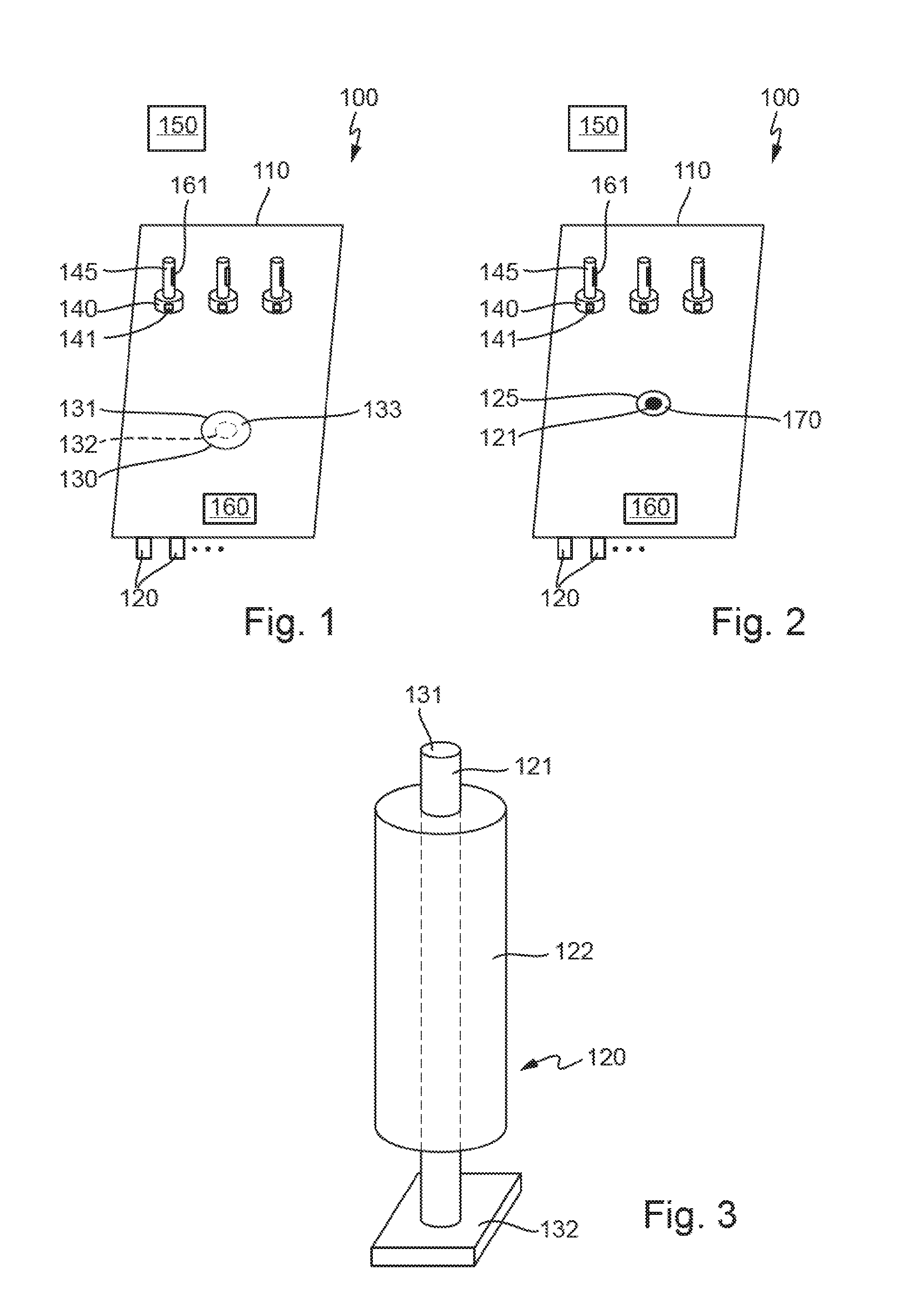
FIG. 1 illustrates schematically a laboratory sample distribution system comprising a rotary plate according to an embodiment of the present disclosure.
FIG. 2 illustrates schematically a laboratory sample distribution system comprising electro-magnetic actuators having a vertically moveable ferromagnetic core according to an embodiment of the present disclosure.
FIG. 3 illustrates schematically an electro-magnetic actuator of FIG. 2 comprising a vertically moveable ferromagnetic core in more detail according to an embodiment of the present disclosure.
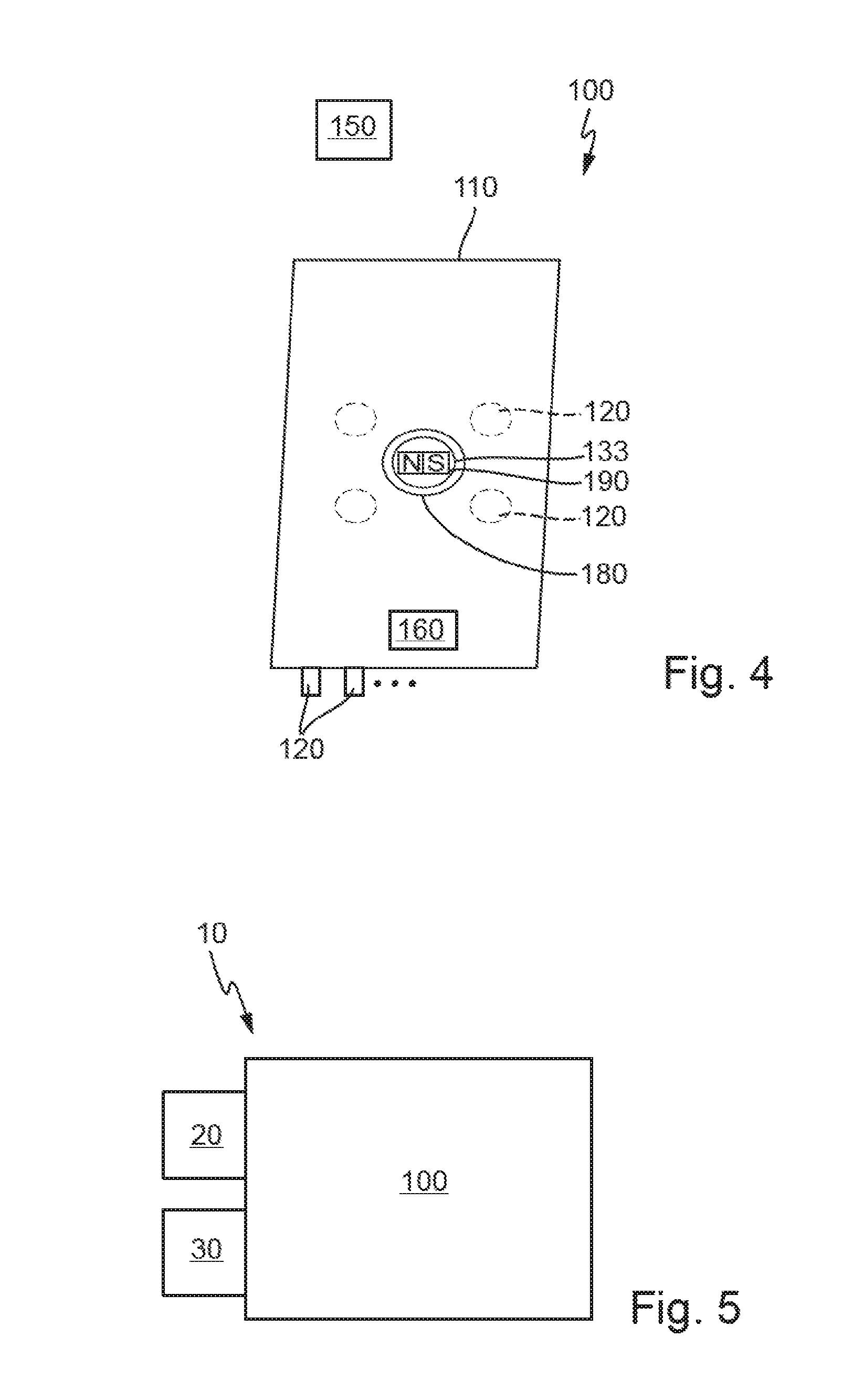
FIG. 4 illustrates schematically depicts a laboratory sample distribution system according to another embodiment of the present disclosure.
FIG. 5 illustrates schematically a laboratory automation system comprising a sample distribution system according to an embodiment of the present disclosure.
DETAILED DESCRIPTION
In the following detailed description of the embodiments, reference is made to the accompanying drawings that form a part hereof, and in which are shown by way of illustration, and not by way of limitation, specific embodiments in which the disclosure may be practiced. It is to be understood that other embodiments may be utilized and that logical, mechanical and electrical changes may be made without departing from the spirit and scope of the present disclosure.
A laboratory sample distribution system can comprise a number of sample container carriers. The number of sample container carriers may e.g. be a number in the range of 1 up to 1,000,000. The sample container carriers can be adapted to carry and/or hold and/or store one or more sample containers. The sample container can typically be designed as a tube made of glass or transparent plastic and typically can have an opening at an upper end. The laboratory sample container may be used to contain, store and transport the laboratory sample such as a blood sample, (blood) serum or plasma sample, a urine sample, separation gel, cruor (blood cells) or a chemical sample. The sample container may be rotationally symmetric.
Each sample container carrier can comprise at least one magnetically active device. The magnetically active device may be a permanent magnet or an electromagnet.
The laboratory sample distribution system can further comprise a transport plane adapted to support or carry the sample container carriers. The transport plane may be a planar plane and the sample container carriers can be placed on top of the transport plane.
The laboratory sample distribution system can further comprise a number of electro-magnetic actuators. The number of electro-magnetic actuators may e.g. be a number in the range of 1 up to 1,000,000.
The electro-magnetic actuators can be stationary arranged below the transport plane, e.g. in rows and columns forming a grid. The electro-magnetic actuators may be coils having a ferromagnetic core. The coils may be adapted to generate a magnetic field. The magnetic field generated by the electro-magnetic actuators may penetrate the transport plane. The magnetic field may interact with the magnetic field of the magnetically active devices of the sample container carriers. The magnetic force applied on the sample container carriers may be a result of this field interaction. Due to the magnetic force, the sample container carriers may slide and/or move over the transport plane. Thus, the electro-magnetic actuators can be adapted to move the sample container carriers on top of the transport plane by applying a magnetic force to the magnetically active devices of the sample container carriers.
The laboratory sample distribution system further comprises a rotating device. The rotating device can comprise a rotating surface. The rotating surface may be a circular surface. The rotating surface may be smaller in its dimensions compared to the dimensions of the transport plane. The rotating surface may be embodied as a specific side, e.g. an upper side, of a rotary element. The rotary element may be rotatably mounted. The rotating device can further comprise a rotating drive adapted to cause a rotational movement of the rotating surface. The rotating drive may be an electric motor or a pneumatic motor. Additionally or alternatively, the electro-magnetic actuators arranged below the transport plane may form the rotating drive.
The laboratory sample distribution system can further comprise a control device, e.g. in form of a Personal Computer (PC) or a microprocessor based control device. The control device can be configured to drive the electro-magnetic actuators. Each sample container carrier may move along a path in response to the driven electro-magnetic actuators. The path of the sample container carriers may be individual paths. The control device can be configured to drive the electro-magnetic actuators such that a sample container carrier to be rotated can move onto the rotating surface. The control device can be further configured to control the rotating drive such that a rotation of the sample container carrier can be caused.
The rotating surface may be larger in its dimensions compared to a footprint of the sample container carrier to be rotated. The rotating surface may be adapted to support or carry the sample container carrier to be rotated. The sample container carrier to be rotated may be placed above or on top of the rotating surface. When placed on the rotating surface, the sample container carrier can rotate together with the carried sample container.
In one embodiment, a (vertical) level of the rotating surface and a level of the transport plane can be identical. The level may be a height having the identical reference point. The identical level of the rotating surface and of the transport plane may prevent tilting of the sample container carrier when the sample container carrier to be rotated moves onto the rotating surface.
In one embodiment, the rotating device can comprise a rotary plate. The rotary plate may be a circular cylinder. An upper side of the rotary plate may form the rotating surface. The upper side may be a facing surface of the rotary plate. The rotating drive can be adapted to cause a rotational movement of the rotary plate. The rotational movement may be caused by a force generated by the rotating drive and applied to the rotary plate. The force may be applied to the rotary plate via a positive connection or a friction-type connection.
In one embodiment, the transport plane can comprise a recess. The recess may have a circular shape. The rotary plate may be arranged inside the recess. The rotary plate may be placed in a rotatable manner inside the recess. Elements defining the recess and the transport plane may be one piece.
In one embodiment, the rotary plate can comprise a magnetically active device having anisotropic magnetic properties such as, for example, an anisotropic magnetic field. A rotating force can be generated by an externally generated magnetic field interacting with a magnetic field of the magnetically active device located in the rotary plate. The magnetically active device located in the rotary plate may be embodied as a permanent magnet, e.g. a bar magnet, or ferromagnetic material.
In one embodiment, the electro-magnetic actuators can comprise respective ferromagnetic cores. The ferromagnetic cores may be embodied as circular cylinders of ferromagnetic material. At least one of the ferromagnetic cores can be arranged vertically movable between an upper vertical position and a lower vertical position. In the lower vertical position, the vertically movable ferromagnetic core may be positioned below the transport plane. In the upper vertical position, a top surface of the vertically moveable ferromagnetic core can contact a bottom surface of the sample container carrier placed above the vertically moveable ferromagnetic core. In the lower vertical position, the top surface of the vertically moveable ferromagnetic core typically does not contact the bottom surface of the sample container carrier. The top surface of the vertically moveable ferromagnetic core can form the rotating surface. The top surface may be an upper side of the vertically moveable ferromagnetic core having a shape in form of a circular cylinder.
The rotating drive can be adapted to cause a rotational movement of the vertically moveable ferromagnetic core. The rotating drive may be functionally coupled to the vertically moveable ferromagnetic core. The rotating drive may apply a force to the vertically moveable ferromagnetic core, wherein the force may cause a rotation of the vertically moveable ferromagnetic core.
In one embodiment, the magnetically active device of a sample container carrier placed above the vertically moveable ferromagnetic core and/or the rotating drive and/or the electro-magnetic actuators can be adapted to move the vertically moveable ferromagnetic core from the upper vertical position to the lower vertical position and/or can be adapted to move the vertically moveable ferromagnetic core from the lower vertical position to the upper vertical position. The movement of the vertically moveable ferromagnetic core may be caused by a force originating from an interaction between a magnetic field and the ferromagnetic material of the ferromagnetic core. The control device may be adapted to control and/or initiate the movement of the vertically moveable ferromagnetic core.
In one embodiment, the rotating surface and a surface of the sample container carrier placed on the rotating surface can form a positive connection or a friction-type connection. The positive connection or friction-type connection may prevent slipping of the sample container carrier at the beginning and/or ending of the rotational movement of the sample container carrier.
In one embodiment, the laboratory sample distribution system can further comprise a barcode scanning unit. The barcode scanning unit can be adapted to scan a barcode label placed on a sample container held by the sample container carrier to be rotated. The control device can be adapted to cause a rotational movement of the rotating surface and consequently of the sample container carrier placed on the rotating surface holding the sample container having the barcode label to be scanned, such that the barcode label can be readable by the barcode scanning unit. The rotating surface may rotate the sample container carrier to be rotated. The barcode scanning unit may be adapted to scan the barcode label during the rotational movement of the sample container carrier. The barcode may determine a destination of the sample container carrier to be transported and/or may comprise information concerning the sample contained in the sample container.
The laboratory automation system can comprises the laboratory sample distribution system described above. The laboratory automation system can further comprise a number of laboratory stations. The number of laboratory stations may e.g. be a number in the range from 1 to 100. The laboratory stations may be e.g. pre-analytical, analytical and/or post-analytical stations.
Pre-analytical stations may be adapted to perform any kind of pre-processing of samples and/or laboratory sample containers.
Analytical stations may be adapted to use a sample or part of the sample and/or a reagent to generate a measuring signal, the measuring signal indicating if and in which concentration an analyte exists.
Post-analytical stations may be adapted to perform any kind of post-processing of samples and/or sample containers.
The pre-analytical, analytical and/or post-analytical stations may comprise at least one of a decapping station, a recapping station, an aliquot station, a centrifugation station, an archiving station, a pipetting station, a sorting station, a tube type identification station, a sample quality determining station, an add-on buffer station, a liquid level detection station, and a sealing/desealing station.
The laboratory sample distribution system can be adapted to distribute the sample containers between the laboratory stations. The laboratory sample distribution system may be adapted to distribute the sample containers between the laboratory stations in response to the scanned barcode labels.
Referring initially to FIG. 1, FIG. 1 schematically depicts a laboratory sample distribution system 100 comprising a number of sample container carriers 140. For the purpose of explanation, only three sample container carriers 140 are shown as representatives for the number of sample container carriers 140. The number of sample container carriers 140 may e.g. be in the range of 10 to 10000. Each sample container carriers 140 can comprise a magnetically active device 141 in the form of a permanent magnet. Moreover, each sample container carrier 140 can hold a sample container 145. A barcode label 161 can be placed on each sample container 145.
The sample container carriers 140 can be placed on a flat transport plane 110 being part of the laboratory sample distribution system 100. The sample container carriers 140 can be adapted to slide and/or move on/over the transport plane 110. Further, a number, or plurality, of electro-magnetic actuators 120 are stationary can be arranged below the transport plane 110. The electro-magnetic actuators 120 can be adapted to generate a magnetic field which can cause a magnetic force on the permanent magnets 141 of the sample container carriers 140. The sample container carriers 140 can move/slide on/over the transport plane 110 as a result of the magnetic force.
The generation of the magnetic field and, therefore, the generation of the magnetic force can be controlled by a control device 150. The control device 150 can be configured to drive the electro-magnetic actuators 120 such that each sample container carrier 140 can slide on an individual path, wherein the path can be planned and/or controlled by the control device 150.
The sample distribution system 100 can further comprise a barcode scanning unit 160. The barcode scanning unit 160 can be adapted to scan the barcode label 161 placed on a respective sample container 145. In order to scan the barcode label 161, the control device 150 can drive the electro-magnetic actuators 120 such that the sample container carrier 140 comprising the sample container 145 having the barcode label 161 to be scanned slides on a rotary plate 133 of a rotating device 130. The rotary plate 133 and the transport plane 110 can have an identical level for preventing that the sample container carrier 140 tilts when sliding from the transport plane 110 on the rotary plate 133.
When the sample container carrier 140 is placed on the rotating surface 131, the control device 150 can control the rotating drive 132 to rotate the sample container carrier 140. The barcode scanning unit 160 can repeatedly try to read the barcode label 161 during the rotation of the sample container carrier 140. When the barcode label 161 is successfully read, the barcode scanning unit 160 can transmit the read barcode to the control device 150 and the control device 150 can stop rotating the rotating surface 131. Then, the control device 150 can drive the electro-magnetic actuators 120 such that the sample container carrier 140 can move off the rotary plate 133.
FIG. 2 shows a further embodiment of a laboratory sample distribution system 100. The laboratory sample distribution system 100 can comprise a transport plane 110 having a cylindrical through hole 125. The through hole 125 can be concentrically arranged with respect to a circular cylindrical vertically moveable ferromagnetic core 121 of an electro-magnetic actuator 120. The through hole 125 can have a diameter that is smaller than a diameter of a respective stand of the sample container carriers 140 and, thus, the sample container carriers 140 can slide and/or move over the opening 125. However, the through hole 125 can have a diameter that is larger than a diameter of the vertically moveable ferromagnetic core 121 and, thus, the vertically moveable ferromagnetic core 121 can penetrate through the transport plane 110.
FIG. 3 shows the electro-magnetic actuator 120 arranged under the through hole 125 in FIG. 2 in more detail. The electro-magnetic actuator 120 can comprise the vertically moveable ferromagnetic core 121 and a coil 122. The vertically moveable ferromagnetic core 121 can be surrounded by the coil 122. The coil 122 can serve to radially fix the ferromagnetic core 121. The front side or upper side of the vertically moveable ferromagnetic core 121 can form the rotating surface 131.
The vertically moveable ferromagnetic core 121 can be functionally coupled to the rotating drive 132, such that the rotating drive 132 may cause a rotation of the ferromagnetic core 121.
The magnetically active device 141 of a sample container carrier 140 placed above the vertically moveable ferromagnetic core can cause a movement of the vertically moveable ferromagnetic core 121 from a lower vertical position to an upper vertical position. When activated, the coil 122 assigned to the vertically moveable ferromagnetic core 121 can cause a movement of the vertically moveable ferromagnetic core 121 from the upper vertical position back to the lower vertical position, such that the vertically moveable ferromagnetic core 121 may transition between its lower and upper vertical position when necessary.
In the lower vertical position, the rotating surface 131 can be located below the transport plane 110. In the upper vertical position, the rotating surface 131 can pass the opening 125 and contact the bottom of the sample container carrier 140 placed above.
A seal 170 may be located between the through hole 125 and the vertically moveable ferromagnetic core 121. The seal 170 can prevent substances from passing the gap between the transport plane 110 and the moveable ferromagnetic core 121. The seal 170 may e.g. be a gap seal, labyrinth seal or profiles interlocking each other.
In order to scan the barcode label 161, in a first step, the vertically moveable ferromagnetic core 121 can be in the lower vertical position and the control device 150 can drive the electro-magnetic actuators 120 such that the sample container carrier 140 carrying the sample container 145 having the barcode label 161 to be scanned slides above the through hole 125.
The magnetically active device 141 of the sample container carrier 140 can cause the vertical movement of the vertically moveable ferromagnetic core 121 to its upper vertical position.
In the upper vertical position, the vertically moveable ferromagnetic core 121 can contact a bottom surface of the sample container carrier 140 like a friction clutch.
The control device 150 can then initiate a rotational movement of the vertically moveable ferromagnetic core 121 by controlling the rotating drive 132.
The barcode scanning unit 160 can then read the barcode label 161 during the rotational movement of the vertically moveable ferromagnetic core 121. When the barcode label 161 is successfully read, the barcode scanning unit 160 can transmit the read barcode to the control device 150. The control device 150 can be adapted to control the rotating drive 132 such that the rotational movement of the vertically moveable ferromagnetic core 121 can stop after the barcode label has been successfully read.
Then, the control device 150 can initiate the movement of the vertically moveable ferromagnetic core 121 back to its lower vertical position.
Further, the control device 150 can drive the electro-magnetic actuators 120 such that the sample container carrier 140 can move off the through hole 125.
Another embodiment of a laboratory sample distribution system 100 is depicted in FIG. 4. The laboratory sample distribution system 100 can comprise a transport plane 110 having a recess 180. The rotary plate 133 can be rotatably inserted into the recess 180. The rotary plate 133 can comprise a magnetically active device 190 in the form of a bar magnet having an anisotropic magnetic field. The bar magnet can extend in a horizontal direction, i.e. parallel to the transport plane 110.
The rotary plate 133 can be rotated by a magnetic force arising from an interaction between the magnetic field of the magnetically active device 190 and the magnetic field of the electro-magnetic actuators 120. The rotary plate 133 including the magnetically active device 190 can form a rotor of an electric motor. The electro-magnetic actuators 120 can form a stator of the electric motor. The electro-magnetic actuators 120 can be controlled such that a rotating magnetic field can be caused, wherein the rotor follows this rotating magnetic field. In other words, the electro-magnetic actuators 120 and the rotary plate 133 can form a synchronous motor.
The rotary plate 133 may contact the bottom surface of the sample container carrier 140 like a friction clutch.
In order to scan the barcode label 161 by the barcode scanning unit 160, the control device 150 can drive the electro-magnetic actuators 120 such that the sample container carrier 140 comprising the sample container 145 having the barcode label 161 to be scanned can slide on the rotary plate 133. Then, the control device 150 can drive the electro-magnetic actuators 120 such that the rotary plate 133 can rotate. The barcode scanning unit 160 can then scan the barcode label 161 during the rotational movement of the rotating device 130, as already discussed with respect to FIGS. 1 to 3.
FIG. 5 schematically depicts a laboratory automation system 10 comprising two laboratory stations 20 and 30. The laboratory stations 20 and 30 can process a sample comprised in a sample container 145. For example, the laboratory station 20 can perform a urinalysis and the laboratory station 30 can perform a blood analysis. The laboratory automation system 10 can further comprise a sample distribution system 100 as e.g. be depicted in FIGS. 1 to 4.
The sample distribution system 100 can be adapted to distribute the sample containers 145 between the laboratory stations 20 and 30. The distribution between the laboratory stations 20 and 30 may be done in response to a scanned barcode label 161 placed on the sample container 145. The distribution may be controlled by the control device 150.
It is noted that terms like "preferably," "commonly," and "typically" are not utilized herein to limit the scope of the claimed embodiments or to imply that certain features are critical, essential, or even important to the structure or function of the claimed embodiments. Rather, these terms are merely intended to highlight alternative or additional features that may or may not be utilized in a particular embodiment of the present disclosure.
Having described the present disclosure in detail and by reference to specific embodiments thereof, it will be apparent that modifications and variations are possible without departing from the scope of the disclosure defined in the appended claims. More specifically, although some aspects of the present disclosure are identified herein as preferred or particularly advantageous, it is contemplated that the present disclosure is not necessarily limited to these preferred aspects of the disclosure.
* * * * *
D00000
D00001
D00002
XML
uspto.report is an independent third-party trademark research tool that is not affiliated, endorsed, or sponsored by the United States Patent and Trademark Office (USPTO) or any other governmental organization. The information provided by uspto.report is based on publicly available data at the time of writing and is intended for informational purposes only.
While we strive to provide accurate and up-to-date information, we do not guarantee the accuracy, completeness, reliability, or suitability of the information displayed on this site. The use of this site is at your own risk. Any reliance you place on such information is therefore strictly at your own risk.
All official trademark data, including owner information, should be verified by visiting the official USPTO website at www.uspto.gov. This site is not intended to replace professional legal advice and should not be used as a substitute for consulting with a legal professional who is knowledgeable about trademark law.