Ambidextrous magazine release for a firearm
Wyssen Sept
U.S. patent number 10,415,913 [Application Number 15/808,287] was granted by the patent office on 2019-09-17 for ambidextrous magazine release for a firearm. This patent grant is currently assigned to Wyssen Defence AG. The grantee listed for this patent is Wyssen Defence AG. Invention is credited to Juerg Wyssen.


| United States Patent | 10,415,913 |
| Wyssen | September 17, 2019 |
Ambidextrous magazine release for a firearm
Abstract
The device (8) allows the release of a detachable magazine from the left and right side of the trigger housing of a firearm, and includes a left lever arm (6) pivotable about a left pivot pin (15) and a right lever arm (7) pivotable about a right pivot pin (14). The right lever arm includes a catch (9) to retain a magazine. The left lever arm (6) includes a left lever extension (12), and the right lever arm (7) includes a right lever extension (13), and these lever extensions are coupled together. When the right lever arm (7), together with its push-button (11), is pivoted to the right, the catch disengages and releases the magazine whilst the left lever arm (6) remains immobile. When the push-button (13) of the left lever arm (6) is pressed to the left, the left lever arm (6) and its left lever extension (12) pivot to the left causing said left lever extension (12) to push the right lever extension (13), and thus the right lever arm (7), to the right, which in turn causes the catch (9) to disengage and release the magazine.
| Inventors: | Wyssen; Juerg (Reichenbach, CH) | ||||||||||
|---|---|---|---|---|---|---|---|---|---|---|---|
| Applicant: |
|
||||||||||
| Assignee: | Wyssen Defence AG (Reichenbach,
CH) |
||||||||||
| Family ID: | 62242981 | ||||||||||
| Appl. No.: | 15/808,287 | ||||||||||
| Filed: | November 9, 2017 |
Prior Publication Data
| Document Identifier | Publication Date | |
|---|---|---|
| US 20180156556 A1 | Jun 7, 2018 | |
Foreign Application Priority Data
| Dec 7, 2016 [CH] | 01614/16 | |||
| Current U.S. Class: | 1/1 |
| Current CPC Class: | F41A 35/06 (20130101); F41A 17/38 (20130101) |
| Current International Class: | F41A 17/38 (20060101); F41A 35/06 (20060101) |
| Field of Search: | ;42/6,7 |
References Cited [Referenced By]
U.S. Patent Documents
| 1397109 | November 1921 | Pedersen |
| 4835892 | June 1989 | Ruger |
| 5519954 | May 1996 | Garrett |
| 7240600 | July 2007 | Bordson |
| 8276502 | October 2012 | Wright |
| 2010/0275485 | November 2010 | Findlay |
| 2012/0291612 | November 2012 | Kincel |
| 2015/0323271 | November 2015 | McGinty |
| 2017/0122689 | May 2017 | Smith |
| 2017/0199000 | July 2017 | Paquette |
| 2018/0347925 | December 2018 | Gibbens |
| WO-2005124263 | Dec 2005 | WO | |||
Attorney, Agent or Firm: Volpe and Koenig, P.C.
Claims
The invention claimed is:
1. A device that is actuatable from left and right sides of a trigger housing of a firearm for releasing a detachable magazine, the device comprising: a left lever arm and a right lever arm (6, 7) coupled together by respective left and right lever extensions (10, 12); the left lever extension (12) of the left lever arm (6) ends in a fork that engages the right lever extension such that movement of either of the left or the right lever arms causes movement of the other of the left or right lever arms; and exactly one single spring (16) that acts only on one of the lever arms and returns both the left and the right lever arms to an initial position after release of an actuation force.
2. The device according to claim 1, further comprising a left pivot pin (15) on which the left lever arm (6) pivots, a right pivot pin (14) on which the right lever arm (7) pivots, and a catch (9) on the right lever arm (7).
3. A device that is actuatable from left and right sides of a trigger housing of a firearm for releasing a detachable magazine, the device comprising: a left lever arm and a right lever arm (6, 7) having different lengths and being coupled together by respective left and right lever extensions (10, 12); a left pivot pin (15) on which the left lever arm (6) pivots; a right pivot pin (14) on which the right lever arm (7) pivots; a catch (9) on the right lever arm (7); a first spring (17), wherein the left lever arm (6) includes a push button (13) that is biased by the first spring (17); a second spring (16) having a different spring force than the first spring, and wherein the right lever arm (7) comprises a push button (11) that is biased by the second spring (16); and an actuation force required on the push-buttons (11, 13) is equal due to a length ratio x:y of the left and right lever extensions (10,12).
Description
INCORPORATION BY REFERENCE
The following documents are incorporated herein by reference as if fully set forth: Swiss Patent Application No. 01614/16, filed Dec. 7, 2016.
BACKGROUND
The present invention concerns a device to release a magazine latched into the receiver of a firearm from the left or right side of the firearm.
Known firearm magazines are retained in the receiver by a catch connected to a push-button mechanism. The push-button is located on the right side of the receiver and serves to release the magazine. This placement is ideal for changing magazines for a right-handed user, but it is complicated, inconvenient and disadvantageous for a left-handed user.
SUMMARY
The object of the present invention is therefore to provide means to easily change magazines for both left-handed and right-handed users.
This object is achieved by a device having one or more features of the invention, which preferably comprises a left lever arm and right lever arm, which are coupled by respective lever extensions. Preferred embodiments are disclosed below and in the claims.
BRIEF DESCRIPTION OF THE DRAWINGS
An exemplary embodiment of the device according to the invention is explained in more detail below with reference to purely schematic drawings. The drawings are as follows:
FIG. 1 is a view, from the left, of a firearm receiver with an inserted magazine,
FIG. 2 is a view from the right of the receiver in FIG. 1,
FIG. 3 is a perspective view of the receiver (without magazine) showing the individual component parts of the device,
FIG. 4 is a perspective view of the component parts of the device in FIG. 3 in assembled form,
FIG. 5 is a view, from above, of the component parts of FIG. 4,
FIG. 6 is a cross-sectional view A-A of FIG. 1,
FIGS. 7, 8, and 9 are enlarged views from above of the device components in FIG. 6, and
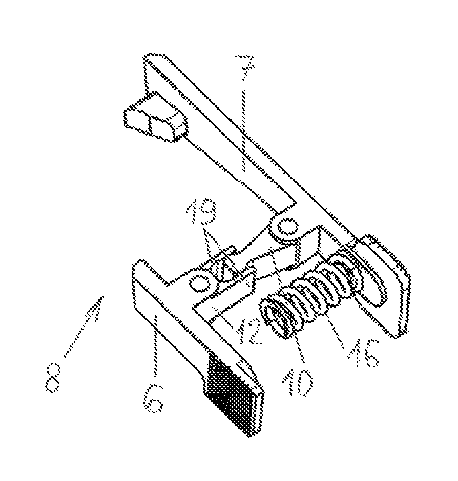
FIG. 10 is a perspective view of a further embodiment of the device.
DETAILED DESCRIPTION OF THE PREFERRED EMBODIMENTS
In accordance with FIGS. 1 and 2, the left and right sides of a firearm receiver 1 are shown with a firing direction 2. The receiver 1 includes a pistol grip 3 and a trigger housing 4 with an inserted magazine 5. In FIG. 1, the left lever arm 6 is partially visible and in FIG. 2 the right lever arm 7 is partially visible.
In FIG. 3, the component parts of the device 8 are shown extracted from the trigger housing 4. The component parts are comprised of a right lever arm 7, which includes: a catch 9 for the magazine, a right lever extension 10, and a push-button 11; and a left lever arm 6 which includes a left extension lever 12, and a push-button 13; as well as a right pivot pin 14, a left pivot pin 15, a strong right spring 16, and a weaker left spring 17.
FIGS. 4 and 5 show the component parts in FIG. 3 in their assembled position, with the omission of the supports for the springs 16 and 17. FIG. 5 shows the distance x, which is the distance between the left pivot pin 15 and the point of contact between the lever extensions 10 and 12, and the distance y, which is the distance between the right pivot pin 14 and the point of contact between the lever extensions 10 and 12. Due to the relative weakness of the left spring 17, a ratio x:y of 2:3 allows the actuation pressure required on the push-buttons 11 and 12 to be the same.
In FIG. 6, the device 8 is shown installed in the trigger housing 4. In FIG. 7, both lever arms 6 and 7 are in a rest position and the magazine is retained by the catch 9. When, as in FIG. 8, the right push-button 11 is pressed, the right lever arm 7 pivots to the right such that the catch 9 releases the magazine. When, as in FIG. 9, the left push-button 13 is pressed, the left lever arm 6 pivots to the left. This causes the left lever extension 12 to press on the right lever extension 10 which in turn causes the right pivoting lever to pivot to the right, again causing the catch 9 to disengage the magazine.
FIG. 10 shows a variant of the device 8 wherein the left lever extension 12 of the left lever arm 6 includes a fork 19 into which the right lever extension extends, such that pressing the right lever arm 7 to the right to release the magazine also causes the left lever arm 6 to pivot to the left. Pressure on the left lever arm 6 to the left causes the fork 19 to pivot the right lever extension 10, and thus the right lever arm 7 to the right, which moves the catch 9 out of engagement with the magazine. This variant requires only a single spring.
* * * * *
D00000
D00001
D00002
D00003
XML
uspto.report is an independent third-party trademark research tool that is not affiliated, endorsed, or sponsored by the United States Patent and Trademark Office (USPTO) or any other governmental organization. The information provided by uspto.report is based on publicly available data at the time of writing and is intended for informational purposes only.
While we strive to provide accurate and up-to-date information, we do not guarantee the accuracy, completeness, reliability, or suitability of the information displayed on this site. The use of this site is at your own risk. Any reliance you place on such information is therefore strictly at your own risk.
All official trademark data, including owner information, should be verified by visiting the official USPTO website at www.uspto.gov. This site is not intended to replace professional legal advice and should not be used as a substitute for consulting with a legal professional who is knowledgeable about trademark law.