Integrated LNG gasification and power production cycle
Allam , et al. Sept
U.S. patent number 10,415,434 [Application Number 15/356,048] was granted by the patent office on 2019-09-17 for integrated lng gasification and power production cycle. This patent grant is currently assigned to 8 Rivers Capital, LLC. The grantee listed for this patent is 8 Rivers Capital, LLC. Invention is credited to Rodney John Allam, Jeremy Eron Fetvedt.


| United States Patent | 10,415,434 |
| Allam , et al. | September 17, 2019 |
Integrated LNG gasification and power production cycle
Abstract
The present disclosure provides an integrated power generating system and method and liquefied natural gas (LNG) vaporization system and method. More particularly, heat from a CO.sub.2 containing stream from the power generating system and method can be used to heat the LNG for re-gasification as gaseous CO.sub.2 from CO.sub.2 containing stream is liquefied. The liquefied CO.sub.2 can be captured and/or recycled back to a combustor in the power generating system and method.
| Inventors: | Allam; Rodney John (Wiltshire, GB), Fetvedt; Jeremy Eron (Raleigh, NC) | ||||||||||
|---|---|---|---|---|---|---|---|---|---|---|---|
| Applicant: |
|
||||||||||
| Assignee: | 8 Rivers Capital, LLC (Durham,
NC) |
||||||||||
| Family ID: | 47178973 | ||||||||||
| Appl. No.: | 15/356,048 | ||||||||||
| Filed: | November 18, 2016 |
Prior Publication Data
| Document Identifier | Publication Date | |
|---|---|---|
| US 20170067373 A1 | Mar 9, 2017 | |
Related U.S. Patent Documents
| Application Number | Filing Date | Patent Number | Issue Date | ||
|---|---|---|---|---|---|
| 13666522 | Nov 1, 2012 | 9523312 | |||
| 61554880 | Nov 2, 2011 | ||||
| 61555096 | Nov 3, 2011 | ||||
| 61597717 | Feb 11, 2012 | ||||
| Current U.S. Class: | 1/1 |
| Current CPC Class: | F17C 9/04 (20130101); F25J 3/04533 (20130101); F25J 3/04018 (20130101); F25J 3/04618 (20130101); F17C 7/04 (20130101); F01K 25/103 (20130101); F02C 3/34 (20130101); F02C 7/143 (20130101); F25J 3/04024 (20130101); F25J 3/04157 (20130101); F25J 3/04127 (20130101); F02C 1/08 (20130101); F17C 2227/0309 (20130101); Y02E 20/16 (20130101); F25J 2230/20 (20130101); F05D 2260/61 (20130101); F25J 2240/70 (20130101); F17C 2201/0109 (20130101); F25J 2230/04 (20130101); F25J 2210/80 (20130101); F05D 2260/213 (20130101); Y02E 60/32 (20130101); F25J 2230/06 (20130101); F25J 2270/904 (20130101); F25J 2260/80 (20130101); F17C 2227/0306 (20130101); F17C 2265/037 (20130101); F25J 2210/62 (20130101); F17C 2227/0135 (20130101); F17C 2265/05 (20130101); F17C 2205/0326 (20130101); F17C 2223/035 (20130101); Y02E 20/18 (20130101); F05D 2260/207 (20130101); Y02E 60/321 (20130101); F17C 2265/07 (20130101); F17C 2227/0157 (20130101); F17C 2223/0161 (20130101); F17C 2227/0323 (20130101); F17C 2221/033 (20130101); F17C 2227/0393 (20130101); F17C 2205/0341 (20130101) |
| Current International Class: | F01K 25/10 (20060101); F02C 1/08 (20060101); F02C 3/34 (20060101); F02C 7/143 (20060101); F17C 9/04 (20060101); F25J 3/04 (20060101); F17C 7/04 (20060101) |
References Cited [Referenced By]
U.S. Patent Documents
| 3376706 | April 1968 | Angelino |
| 3503208 | March 1970 | Schmidt |
| 3736745 | June 1973 | Karig |
| 3837788 | September 1974 | Craig et al. |
| 3868817 | March 1975 | Marion et al. |
| 3971211 | July 1976 | Wethe et al. |
| 3976443 | August 1976 | Paull et al. |
| 3992891 | November 1976 | Pocrnja |
| 4036028 | July 1977 | Mandrin |
| 4154581 | May 1979 | Nack et al. |
| 4191500 | March 1980 | Oberg et al. |
| 4193259 | March 1980 | Muenger et al. |
| 4206610 | June 1980 | Santhanam |
| 4231226 | November 1980 | Griepentrog |
| 4461154 | July 1984 | Allam |
| 4498289 | February 1985 | Osgerby |
| 4522628 | June 1985 | Savins |
| 4602483 | July 1986 | Wilks et al. |
| 4702747 | October 1987 | Meyer et al. |
| 4721420 | January 1988 | Santhanam et al. |
| 4765143 | August 1988 | Crawford et al. |
| 4765781 | August 1988 | Wilks et al. |
| 4839030 | June 1989 | Comolli et al. |
| 4852996 | August 1989 | Knop et al. |
| 4881366 | November 1989 | Nurse |
| 4942734 | July 1990 | Markbreiter et al. |
| 4957515 | September 1990 | Hegarty |
| 4995234 | February 1991 | Kooy et al. |
| 4999992 | March 1991 | Nurse |
| 4999995 | March 1991 | Nurse |
| 5175995 | January 1993 | Pak et al. |
| 5247791 | September 1993 | Pak et al. |
| 5265410 | November 1993 | Hisatome |
| 5353721 | October 1994 | Mansour et al. |
| 5467722 | November 1995 | Meratla |
| 5520894 | May 1996 | Heesink et al. |
| 5590519 | January 1997 | Almlof et al. |
| 5595059 | January 1997 | Huber et al. |
| 5692890 | December 1997 | Graville |
| 5709077 | January 1998 | Beichel |
| 5715673 | February 1998 | Beichel |
| 5724805 | March 1998 | Golomb et al. |
| 5802840 | September 1998 | Wolf |
| 5906806 | May 1999 | Clark |
| 5937652 | August 1999 | Abdelmalek |
| 6024029 | February 2000 | Clark |
| 6117916 | September 2000 | Allam et al. |
| 6148602 | November 2000 | Demetri |
| 6170264 | January 2001 | Viteri et al. |
| 6196000 | March 2001 | Fassbender |
| 6199364 | March 2001 | Kendall et al. |
| 6202574 | March 2001 | Liljedahl et al. |
| 6209307 | April 2001 | Hartman |
| 6260348 | July 2001 | Sugishita et al. |
| 6263661 | July 2001 | Van der Burgt et al. |
| 6269624 | August 2001 | Frutschi et al. |
| 6289666 | September 2001 | Ginter |
| 6298664 | October 2001 | .ANG.sen et al. |
| 6333015 | December 2001 | Lewis |
| 6360561 | March 2002 | Allam et al. |
| 6389814 | May 2002 | Viteri et al. |
| 6430916 | August 2002 | Sugishita et al. |
| 6532745 | March 2003 | Neary |
| 6536205 | March 2003 | Sugishita et al. |
| 6543214 | April 2003 | Sasaki et al. |
| 6550234 | April 2003 | Guillard |
| 6598398 | July 2003 | Viteri et al. |
| 6612113 | September 2003 | Guillard |
| 6622470 | September 2003 | Viteri et al. |
| 6629414 | October 2003 | Fischer |
| 6637183 | October 2003 | Viteri et al. |
| 6684643 | February 2004 | Frutschi |
| 6764530 | July 2004 | Iijima |
| 6775987 | August 2004 | Sprouse et al. |
| 6802178 | October 2004 | Sprouse et al. |
| 6820689 | November 2004 | Sarada |
| 6824710 | November 2004 | Viteri et al. |
| 6871502 | March 2005 | Marin et al. |
| 6877319 | April 2005 | Linder et al. |
| 6877322 | April 2005 | Fan |
| 6898936 | May 2005 | Ochs et al. |
| 6910335 | June 2005 | Viteri et al. |
| 6918253 | July 2005 | Fassbender |
| 6945029 | September 2005 | Viteri |
| 6945052 | September 2005 | Frutschi et al. |
| 6993912 | February 2006 | Fischer |
| 7007474 | March 2006 | Ochs et al. |
| 7007486 | March 2006 | Sprouse et al. |
| 7021063 | April 2006 | Viteri |
| 7022168 | April 2006 | Schimkat et al. |
| 7043920 | May 2006 | Viteri et al. |
| 7074033 | July 2006 | Neary |
| 7089743 | August 2006 | Frutschi et al. |
| 7111463 | September 2006 | Sprouse et al. |
| 7124589 | October 2006 | Neary |
| 7147461 | December 2006 | Neary |
| 7191587 | March 2007 | Marin et al. |
| 7192569 | March 2007 | Stewart |
| 7281590 | October 2007 | Van de Waal |
| 7284362 | October 2007 | Marin et al. |
| 7299637 | November 2007 | Becker |
| 7303597 | December 2007 | Sprouse et al. |
| 7328581 | February 2008 | Christensen et al. |
| 7334631 | February 2008 | Kato et al. |
| 7360639 | April 2008 | Sprouse et al. |
| 7363764 | April 2008 | Griffin et al. |
| 7377111 | May 2008 | Agnew |
| 7387197 | June 2008 | Sprouse et al. |
| 7402188 | July 2008 | Sprouse |
| 7469544 | December 2008 | Farhangi |
| 7469781 | December 2008 | Chataing et al. |
| 7516607 | April 2009 | Farhangi et al. |
| 7516609 | April 2009 | Agnew |
| 7547419 | June 2009 | Sprouse et al. |
| 7547423 | June 2009 | Sprouse et al. |
| 7553463 | June 2009 | Zauderer |
| 7615198 | November 2009 | Sprouse et al. |
| 7717046 | May 2010 | Sprouse et al. |
| 7722690 | May 2010 | Shires et al. |
| 7731783 | June 2010 | Sprouse et al. |
| 7739874 | June 2010 | Nigro |
| 7740671 | June 2010 | Yows et al. |
| 7740672 | June 2010 | Sprouse |
| 7814975 | October 2010 | Hagen et al. |
| 7826054 | November 2010 | Zillmer et al. |
| 7827797 | November 2010 | Pronske et al. |
| 7874140 | January 2011 | Fan et al. |
| 7882692 | February 2011 | Pronske et al. |
| 7927574 | April 2011 | Stewart |
| 7950243 | May 2011 | Gurin |
| 8043588 | October 2011 | Hustad et al. |
| 8088196 | January 2012 | White et al. |
| 8109095 | February 2012 | Henriksen et al. |
| 8220248 | July 2012 | Wijmans et al. |
| 2002/0134085 | September 2002 | Frutschi |
| 2003/0101736 | June 2003 | Cheng et al. |
| 2003/0131582 | July 2003 | Anderson et al. |
| 2004/0011057 | January 2004 | Huber |
| 2004/0123601 | July 2004 | Fan |
| 2005/0126156 | June 2005 | Anderson et al. |
| 2005/0223712 | October 2005 | Briesch et al. |
| 2006/0032228 | February 2006 | Marin et al. |
| 2006/0242907 | November 2006 | Sprouse et al. |
| 2007/0180768 | August 2007 | Briesch et al. |
| 2007/0274876 | November 2007 | Chiu et al. |
| 2008/0010967 | January 2008 | Griffin et al. |
| 2008/0104958 | May 2008 | Finkenrath et al. |
| 2008/0115500 | May 2008 | MacAdam et al. |
| 2008/0166672 | July 2008 | Schlote et al. |
| 2008/0187877 | August 2008 | Fitzsimmons et al. |
| 2008/0190214 | August 2008 | Ubowski |
| 2008/0302133 | December 2008 | Saysset et al. |
| 2008/0309087 | December 2008 | Evulet et al. |
| 2009/0025390 | January 2009 | Christensen et al. |
| 2009/0061264 | March 2009 | Agnew |
| 2009/0130660 | May 2009 | Faham et al. |
| 2009/0229271 | September 2009 | De Ruyck et al. |
| 2009/0260585 | October 2009 | Hack et al. |
| 2009/0277189 | November 2009 | Eie et al. |
| 2009/0301054 | December 2009 | Simpson et al. |
| 2010/0017639 | January 2010 | Chen et al. |
| 2010/0018218 | January 2010 | Riley et al. |
| 2010/0024378 | February 2010 | Ackermann et al. |
| 2010/0024381 | February 2010 | Ackermann et al. |
| 2010/0024433 | February 2010 | Ackermann et al. |
| 2010/0031668 | February 2010 | Kepplinger |
| 2010/0077752 | April 2010 | Papile |
| 2010/0146971 | June 2010 | Mak |
| 2010/0167221 | July 2010 | Canacik et al. |
| 2011/0036011 | February 2011 | Sprouse et al. |
| 2011/0179799 | July 2011 | Allam et al. |
| 2011/0289941 | December 2011 | Gonzalez Salazar et al. |
| 43 03 174 | Aug 1994 | DE | |||
| 19952884 | May 2001 | DE | |||
| 0 277 777 | Aug 1988 | EP | |||
| 2 390 475 | Nov 2011 | EP | |||
| 2225905 | Sep 1990 | JP | |||
| 2001-132472 | May 2001 | JP | |||
| 2001-41007 | Feb 2004 | JP | |||
| 2006-526724 | Nov 2006 | JP | |||
| 2008-534741 | Aug 2008 | JP | |||
| 2009-541522 | Nov 2009 | JP | |||
| 2011-032954 | Feb 2011 | JP | |||
| 2011-246710 | Dec 2011 | JP | |||
| WO 2007/148984 | Dec 2007 | WO | |||
| WO 2008/136122 | Nov 2008 | WO | |||
Other References
|
Angelino et al., "Carbon Dioxide Power Cycles Using Liquid Natural Gas as Heat Sink," Applied Thermal Engineering, 2009, doi: 10.1016/j.applthermaleng.2009.03.003 , pp. 1-42. cited by applicant . Combs, Jr. "An Investigation of the Supercritical CO2 Cycle (Feher Cycle) for Shipboard Application," 1977, Submitted in Partial Fulfillment of the Requirements for the Degree of Ocean Engineer and the Degree of Master ofScience in Mechanical Engineering at the Massachusetts Institute ofTechnology, 148. cited by applicant . Dostal et al., "A Supercritical Carbon Dioxide Cycle for Next Generation Nuclear Reactors," 2004, (Research Paper) Advanced Nuclear Power Technology Program at MIT, 326 pages. cited by applicant . Hong et al., "Analysis of Oxy-Fuel Combustion Power Cycle Utilizing a Pressurized Coal Combustor," Energy, Available Online Jun. 21, 2009, pp. 1332-1340, vol. 34, No. 9. cited by applicant . Iantovski et al., "Highly Efficient Zero Emission CO2-Based Power Plant" Energy Convers. Mgmt, 1997, Suppl. pp. S141-S146, vol. 38. cited by applicant . E.I. Yantovskii et al. , "Computer Exergonomics of Power Plants Without Exhaust Gases," Energy Convers. Mgmt., Publ. 1992, vol. 33, No. 5-8, pp. 405-412. cited by applicant . Wall et al., "A Zero Emission Combustion Power Plant for Enhanced Oil Recovery," Energy, 1995, pp. 823-828, vol. 20, No. 8. cited by applicant . http://www.graz-cycle.tugraz.at/pdfs/Bolland_Kyamsdal_Boden_Liege.pdf; Boland, "A Thermodynamic Comparison of the Oxy-Fuel Power Cycles Water-Cycle, Graz-Cycle and Matiant-Cycle," Norwegian University of Science and Technology, Trondheim, Norway. cited by applicant . http://www2.ulg.ac.be/genienuc/pageco2.htm; Universite de Liege, Department of Power Generation, "CO2 Researches". cited by applicant. |
Primary Examiner: Walthour; Scott J
Attorney, Agent or Firm: Womble Bond Dickinson (US) LLP
Parent Case Text
CROSS-REFERENCE TO RELATED APPLICATIONS
The present application is a divisional of U.S. application Ser. No. 13/666,522 and claims priority to U.S. Provisional Application No. 61/554,880, filed Nov. 2, 2011, U.S. Provisional Application No. 61/555,096, filed Nov. 3, 2011, and U.S. Provisional Application No. 61/597,717, filed Feb. 11, 2012, the disclosures of which are incorporated herein by reference in their entireties.
Claims
The invention claimed is:
1. A power generating system comprising: a combustor adapted to receive a carbonaceous fuel, oxygen, and pressurized, recycled CO.sub.2 and output a pressurized combustion product comprising CO.sub.2; a power producing turbine fluidly connected with the combustor and adapted to expand the pressurized combustion product comprising CO.sub.2 and output a turbine exhaust comprising CO.sub.2; an economizer heat exchanger fluidly connected at a hot end of the economizer heat exchanger with the power producing turbine and the combustor and adapted to transfer heat from the turbine exhaust stream comprising CO.sub.2 to the pressurized, recycled CO.sub.2 and output from a cold end of the economizer heat exchanger a cooled turbine exhaust comprising CO.sub.2; a separator fluidly connected to the economizer heat exchanger and adapted to output substantially pure CO.sub.2; a liquid CO.sub.2 pump adapted to compress liquefied CO.sub.2; a CO.sub.2 liquefier heat exchanger fluidly connected at a cold end of the CO.sub.2 liquefier heat exchanger to the separator and to the economizer heat exchanger and fluidly connected at a hot end of the CO.sub.2 liquefier heat exchanger to both of an input of the liquid CO.sub.2 pump and an output of the liquid CO.sub.2 pump; a source of liquefied natural gas (LNG) fluidly connected with the hot end of the CO.sub.2 liquefier heat exchanger; and a further heat exchanger positioned between the economizer heat exchanger and the CO.sub.2 liquefier heat exchanger so as to be fluidly connected with the cold end of the economizer heat exchanger and the hot end of the CO.sub.2 liquefier heat exchanger; wherein the further heat exchanger includes an inlet fluidly connected with an outlet on the cold end of the economizer heat exchanger, an inlet fluidly connected with an outlet on the hot end of the CO.sub.2 liquefier heat exchanger, and an outlet fluidly connected with an inlet on the hot end of the CO.sub.2 liquefier heat exchanger.
2. The system of claim 1, wherein the separator is positioned between the outlet of the further heat exchanger and the inlet on the hot end of the CO.sub.2 liquefier heat exchanger.
3. The system of claim 1, wherein the power producing turbine is adapted to provide shaft power for the liquid CO.sub.2 pump.
4. The system of claim 1, further comprising an air separation plant.
5. The system of claim 4, wherein the air separation plant is a cryogenic air separation plant.
Description
FIELD OF THE DISCLOSURE
The present disclosure relates to integration of a power production system with a liquefied natural gas re-gasification system. More particularly, the integrated system utilizes heat exchange to cool a recycle stream in the power production system and to heat and gasify an LNG stream.
BACKGROUND
Natural gas (i.e., methane, predominately) is commonly liquefied for ease of storage and/or transport and is re-gasified for end-use, typically in an LNG gasification facility. Generally, re-gasification requires pressurizing the natural gas ("NG") to a required pipeline pressure--e.g., about 1,000 psi (6.9 MPa). After pressurization, the NG typically is still at or near cryogenic temperatures and therefore must be heated to raise the temperature to ambient. This is often carried out with a water bath heated with a submerged combustion burner, which can use part of the ambient temperature NG as fuel. Often, about 1-2% of the LNG at a re-gasification facility must be burned to heat the LNG to ambient temperature after it is pressurized, and this creates significant effects on efficiency, cost, fossil fuel consumption, and CO.sub.2 emissions. It would be useful to provide systems and methods for re-gasification that address these matters.
Natural gas, coal, and other carbonaceous fuels are commonly used in power production cycles, such as gas turbine combined cycle systems, supercritical pulverized coal systems, and others. Other power production systems utilizing natural gas, coal, and other carbonaceous fuels as a fuel also have been used or proposed. Power production efficiency, however, is a limiting factor in the integration of new power production technologies. Accordingly, it would be useful to provide systems and methods for power production with improved efficiency.
SUMMARY OF THE DISCLOSURE
The present disclosure provides an integration of systems in a manner that can improve efficiencies and reduce costs in relation to both systems. More particularly, the disclosure provides for the integration of a power production system and cycle with an LNG re-gasification system and method. The disclosure also provides for the integration of a CO.sub.2 shipping process with an LNG shipping process.
Systems and methods for power generation using predominately CO.sub.2 in a closed combustion cycle are described in U.S. Pat. Pub. No. 2011/0179799, the disclosure of which is incorporated herein by reference in its entirety, and in various embodiments, one or more components or conditions of the power generating systems and methods disclosed therein can be incorporated into the power generating systems and methods of the present disclosure. The combustion cycle can use a high pressure ratio turbine that expands a mixture of combustion products that are formed in the combustion of a fuel in oxygen in the presence of CO.sub.2 working fluid stream (which typically is recycled--at least in part--through the closed system). In various embodiments, a CO.sub.2 cycle such as described above can be used in power production using NG, coal, or other carbonaceous materials as a fuel source. Hot turbine exhaust is used to partially preheat the recycled CO.sub.2 working fluid stream in an economizer heat exchanger. The recycled CO.sub.2 working fluid stream also can be heated using a secondary heat source, such as heat derived from the compression energy from an O.sub.2 production plant that is used to provide oxygen for combustion. Fuel and combustion-derived impurities (e.g., sulfur compounds, CO.sub.2, H.sub.2O, ash, Hg, etc.) can be separated for disposal with no atmospheric emissions. The system can produce a high pressure CO.sub.2 recycle stream (i.e., that is recycled as the working fluid) and a high pressure CO.sub.2 product stream (i.e., excess CO.sub.2 that is not recycled into the combustion cycle and that can be captured for uses, such as enhanced oil recovery, or for sequestration). This can be achieved by compressing the cooled turbine exhaust stream from the economizer heat exchanger in a multistage compression system.
The present disclosure provides the ability to integrate an NG, coal, or other carbonaceous materials fueled CO.sub.2 cycle power production system with LNG re-gasification such that heat from one or more streams of the CO.sub.2 power generation system can be utilized for heating the compressed NG while simultaneously cooling one or more process streams from the CO.sub.2 power cycle. In some embodiments, cooling from the compressed NG stream in the LNG re-gasification system can be sufficient so as to allow for elimination of one or more compression components from the CO.sub.2 cycle and rather liquefy a gaseous, recycle stream against the cryogenic LNG. Integration of the power generation system with the LNG gasification system can increase the efficiency of the CO.sub.2 cycle power production process to greater than 60%.
In further embodiments, integration of an LNG heating process with a CO.sub.2 compression step in a closed cycle power generation system and process can be useful to reduce or eliminate the fuel consumption required for heating LNG in a conventional re-gasification process. Further, liquefying a CO.sub.2 rich turbine exhaust stream leaving the cool end of an economizer heat exchanger following separation of liquid water from the turbine exhaust stream can be carried out simultaneously with heating of a first LNG stream to a desired temperature, such as greater than about 32.degree. C. (0.degree. F.). Thereafter, the liquid CO.sub.2 at high density can be pumped to a sufficiently high pressure to be recycled back into a combustion process as the CO.sub.2 working fluid, and this can be achieved with a very significant power savings compared to a normal gas compression procedure. In further embodiments, the natural gas from the heat exchanger used to liquefy the CO.sub.2 can be heated to near ambient temperature so that it can be delivered to a natural gas pipeline. For example, this can be accomplished by cooling a stream of cooling water to a desired temperature, such as about 0.degree. C. to about 10.degree. C. This cold water then can be used in a closed cycle system to cool air being compressed before delivery to a cryogenic oxygen plant in order to reduce air compressor power consumption. Still further, the liquefied CO.sub.2 stream can be cooled to a temperature that is within about 10.degree. C. of the CO.sub.2 freezing temperature, and this can be useful to minimize the liquid CO.sub.2 pump power while maximizing liquid CO.sub.2 density. Beneficially, a portion of the heated natural gas leaving the CO.sub.2 liquefaction heat exchanger can be recycled and mixed with the cold, high pressure LNG leaving the main LNG pumps to provide a natural gas fluid at a temperature within about 10.degree. C. above the CO.sub.2 freezing temperature. This mixed natural gas fluid can be used as the cooling medium in the CO.sub.2 liquefying heat exchanger. In other embodiments, a parallel natural gas fired LNG heater can be provided at the necessary operating temperature as a standby system with controls allowing instant switchover from the main power generation system to the LNG heater in the event the power generation system must be offline. Similarly, at least one additional primary LNG pump discharging at the required pipeline pressure can be provided so that if the on-line LNG pump supplying the power generation system goes offline, the second pump can come on-line and take over the LNG supply requirements. Further, a second LNG pump discharging at the required high pressure can be provided and can be used to provide a second natural gas stream for use as fuel for the combustor in the power generation system. The refrigeration from this stream can be recovered by heating it in the CO.sub.2 liquefying heat exchanger in a parallel circuit to the first LNG circuit.
In certain embodiments, the present disclosure can provide methods of generating power. For example, a method of generating power can comprise combusting a carbonaceous fuel in a combustor in the presence of oxygen and CO.sub.2 to form a CO.sub.2 recycle stream and to produce a combined combustion product stream. The method further can comprise passing the combined combustion product stream through a turbine to generate power and form a turbine exhaust stream comprising supercritical CO.sub.2, passing the turbine exhaust stream comprising supercritical CO.sub.2 through a first heat exchanger to convert the supercritical CO.sub.2 to a stream comprising gaseous CO.sub.2, and passing the gaseous CO.sub.2 stream through a second heat exchanger to form a liquid CO.sub.2 stream. The step of passing the gaseous CO.sub.2 stream through the second heat exchanger further can comprise passing a liquefied natural gas (LNG) stream through the second heat exchanger and thus forming a gaseous natural gas (NG) stream. The method further can comprising pressurizing the liquid CO.sub.2 stream to form a recycle stream comprising supercritical CO.sub.2 and passing the recycle CO.sub.2 stream to the combustor. If desired, a fraction of the LNG can be utilized as fuel for the combustor, and a NG product stream can be provided at temperatures and pressures suitable for input to a natural gas distribution pipeline.
In further embodiments, a method of generating power can comprise the following steps: combusting a carbonaceous fuel in a combustor in the presence of oxygen and CO.sub.2 to form a CO.sub.2 recycle stream and to produce a combined combustion product stream; passing the combined combustion product stream through a turbine to generate power and form a turbine exhaust stream comprising CO.sub.2; passing the turbine exhaust stream comprising CO.sub.2 through a first heat exchanger so as to transfer heat from the turbine exhaust stream to the CO.sub.2 recycle stream and form a cooled turbine exhaust stream; passing a liquefied natural gas (LNG) stream and CO.sub.2 from the cooled turbine exhaust stream through a second heat exchanger so as to cool and liquefy the CO.sub.2 and so as to heat and vaporize the LNG to form a liquefied CO.sub.2 stream and a gaseous natural gas (NG) stream; pressurizing the liquefied CO.sub.2 stream to form the CO.sub.2 recycle stream; and passing the recycle CO.sub.2 stream to the combustor. The first heat exchanger can be characterized as a combustion product heat exchanger, and the second heat exchanger can be characterized as a CO.sub.2 liquefier heat exchanger.
The combustor can be any combustor suitable for combustion at the required temperature and pressure. A CO.sub.2 recycle stream passed to the combustor can be provided at a pressure of about 150 bar (15 MPa) or greater, about 200 bar (20 MPa) or greater, about 250 bar (25 MPa) or greater, or about 300 bar (30 MPa) or greater. In other embodiments, the pressure can be about 150 bar (15 MPa) to about 400 bar (40 MPa), about 200 bar (20 MPa) to about 380 bar (38 MPa), or about 250 bar (25 MPa) to about 350 bar (35 MPa). Combustion in the combustor can be carried out at a temperature, for example, of about 500.degree. C. or greater, about 600.degree. C. or greater, or about 700.degree. C. or greater. In other embodiments, combustion can be carried out at a temperature of about 500.degree. C. to about 1600.degree. C., about 550.degree. C. to about 1200.degree. C., or about 600.degree. C. to about 1000.degree. C. In other embodiments, even further temperature ranges can be used, as otherwise described herein.
The power generation method can be characterized by the pressure ratio across the turbine. Specifically, the ratio of the pressure of the combined combustion product stream (entering the turbine) to the pressure of the turbine exhaust stream comprising CO.sub.2 (exiting the turbine) can be 12 or less, about 10 or less, or about 8 or less. In other embodiments, the pressure ratio can be about 4 to about 12, about 5 to about 10, or about 6 to about 10.
The combustion product heat exchanger through which the combined combustion product stream is directly passed can be a multi-stage heat exchanger or a series to two or more, preferably three, serial heat exchangers. In such series, the first serial heat exchanger (passing from hot end to cold end) can transfer heat over a high, broad temperature range--e.g., from the turbine outlet temperature to the range of about 150.degree. C. to about 200.degree. C. The second serial heat exchanger can transfer heat over a middle, narrower temperature range--e.g., from the exit temperature of the first serial heat exchanger to the range of about 80.degree. C. to about 140.degree. C. The third serial heat exchanger can transfer heat over a low temperature range--e.g., the range of about 20.degree. C. to about 75.degree. C. Such ranges likewise can apply to fluids passed from the cold end to the hot end of each heat exchanger in the series. Such series can be beneficial in that added heating of the CO.sub.2 recycle stream passing from the cold end of the serial heat exchangers to the hot end of the heat exchangers can be input at a defined point. For example, the stream exiting the third serial heat exchanger and entering the second serial heat exchanger can be split, and one fraction can enter the second serial heat exchanger while the other fraction is heated from an external source, such as the heat of compression captured from an air separation plant. The higher heated fraction can then be joined with the stream exiting the second serial heat exchanger and entering the first serial heat exchanger. Such added heat can be beneficial to bring the temperature of the CO.sub.2 recycle stream to within a preferable threshold relative to the temperature of the turbine exhaust stream. Specifically, the CO.sub.2 recycle stream can be heated to within 50.degree. C. or less, 40.degree. C. or less, or 30.degree. C. or less of the temperature of the turbine exhaust stream.
The power generation method further can be characterized by the nature of the LNG that is processed in parallel to the combustion cycle. For example, stored LNG often can be at a pressure that is less than about 10 bar (1 MPa), less than about 5 bar (0.5 MPa), or less than about 1 bar (0.1 MPa). Thus, it can be beneficial for the LNG passed into the second heat exchanger can be provided at an increased pressure. Specifically, the LNG can be pumped to a pressure of about 30 bar (3 MPa) or greater, about 40 bar (4 MPa) or greater, about 50 bar (5 MPa) or greater, or about 60 bar (6 MPa) or greater. In other embodiments, the LNG can be pumped to a pressure of about 50 bar (5 MPa) to about 90 bar (9 MPa), about 55 bar (5.5 MPa) to about 85 bar (8.5 MPa) or about 60 bat (6 MPa) to about 80 bar (8 MPa).
LNG also typically can be stored at a temperature that is below the freezing point of CO.sub.2 at working pressures discussed herein. Thus, it can be useful to increase the temperature of the LNG prior to passing the LNG through the second heat exchanger that removes heat from the CO.sub.2 stream and liquefies the CO.sub.2 stream. In certain embodiments, this can be achieved through utilization of a portion of the heated, gaseous NG stream that is formed in (and exits) the second heat exchanger (the CO.sub.2 liquefier heat exchanger). Specifically, a fraction of the gaseous NG stream formed by the second heat exchanger can be withdrawn and input to the LNG stream that is passed into the second heat exchanger, preferably immediately prior to passage of the LNG stream into the second heat exchanger. The fraction of the gaseous NG stream input to the LNG stream can be an amount that is sufficient to raise the temperature of the LNG stream to a temperature that is above the CO.sub.2 solidification temperature. Preferably, it is sufficient to raise the temperature of the LNG stream to a temperature that also is within about 25.degree. C., within about 20.degree. C., within about 15.degree. C., or within about 10.degree. C. of the CO.sub.2 solidification temperature.
Heat exchange in the second heat exchanger also can be characterized in relation to the temperature to which the CO.sub.2 stream is cooled. Specifically, the CO.sub.2 from the cooled turbine exhaust stream can be cooled (which can be referred to as being sub-cooled) in the second heat exchanger to a temperature that is above the CO.sub.2 solidification temperature and is within about 40.degree. C., within about 30.degree. C., or within about 20.degree. C. of the CO.sub.2 solidification temperature.
The liquefied CO.sub.2 stream beneficially can be pressurized to a pressure suitable for injection to the combustor as the CO.sub.2 recycle stream. Specifically, the step of pressurizing the CO.sub.2 recycle stream can comprise passing the CO.sub.2 recycle stream through a liquid pump. In some embodiments, the power generating turbine and the liquid pump can be arranged such that the power generating turbine produces shaft power that can be used to drive the liquid pump. The liquefied and pressurized CO.sub.2 stream exiting the liquid pump can be heated. In particular, the heating can comprise passing the pressurized CO.sub.2 recycle stream back through the second heat exchanger. In some embodiments, the CO.sub.2 recycle stream can be heated to a temperature of about -20.degree. C. or greater, about -10.degree. C. or greater, about 0.degree. C. or greater, or about 10.degree. C. or greater.
In addition to the first and second heat exchangers, one or more further heat exchangers can be utilized to preserve heat exchange potential in one or more components of the power generation system. This heat exchange potential can be applied to a variety of streams in the presently disclosed methods.
For example, in some embodiments, the carbonaceous fuel used in the combustor can comprise NG derived from the LNG stream. Other embodiments of the method can utilize additional or different carbonaceous fuels, including coal, biomass, and the like. In order to provide a NG stream to the combustor, the methods can comprise passing the LNG through a first pump and a second pump to increase the pressure thereof, such as to a pressure already described above. The LNG exiting the second pump can then be heated, such as to a temperature of about 100.degree. C. or greater, about 150.degree. C. or greater, about 200.degree. C. or greater, or about 250.degree. C. or greater. Such heating can be achieved by passing the LNG through the second heat exchanger so as to form a gaseous NG stream. If desired, the gaseous NG stream can be further heated by other heat exchange means.
For example, heating of the gaseous NG stream can comprise utilizing heat of compression from an air separation plant, specifically a cryogenic air separation plant. Such air separation plant can be integrated into the power generation system such that oxygen formed in the air separation plant can be directly input to the combustor in the power generation method. Further means for utilizing heat of compression from an air separation plant are discussed below.
In certain embodiments of the present disclosure, the power generation method can further comprise passing the cooled turbine exhaust stream through a third heat exchanger after passage through the first heat exchanger and prior to passage through the second heat exchanger. The third heat exchanger can be a low temperature heat exchanger, and such passage through the third heat exchanger can be effective to provided intermediate cooling of the turbine exhaust stream. Passage of the turbine exhaust stream through the first heat exchanger significantly cools the turbine exhaust stream through a relatively high temperature range--e.g., from a temperature in the range of about 600.degree. C. to about 800.degree. C. (or a further temperature near a combustion temperature discussed herein) to a temperature in the range of about 50.degree. C. to about 20.degree. C. The thusly cooled turbine exhaust stream then receives intermediate cooling in the third heat exchanger--for example, further cooling the turbine exhaust stream to a temperature of about -10.degree. C. to about 15.degree. C., about -5.degree. C. to about 12.degree. C., or about 0.degree. C. to about 10.degree. C. This intermediate cooling thus can be carried out prior to passage of the turbine exhaust stream through the second heat exchanger, which provides sub-cooling and liquefaction of the CO.sub.2 from the turbine exhaust stream. In the third heat exchanger, the turbine exhaust stream can be cooled against a fraction of the gaseous NG stream exiting the second heat exchanger.
After passage through the third heat exchanger and prior to passage through the second heat exchanger, the cooled turbine exhaust stream can be passed through one or both of a liquid water separator and a desiccant drier. With water removed from the turbine exhaust stream, a purified stream of CO.sub.2 from the cooled turbine exhaust stream can be thus provided as a dried CO.sub.2 stream. If desired (and depending upon the combustion fuel used), one or more further separators and/or filters can be included to remove further contaminants from the turbine exhaust stream. Preferably, the CO.sub.2 stream from the turbine exhaust can be input to the second heat exchanger having a CO.sub.2 purity of about 95% or greater, about 97% or greater, or about 99% or greater. In some embodiments, the dried CO.sub.2 stream can be dried to a dew point of about -30.degree. C. or below, about -40.degree. C. or below, about -50.degree. C. or below, or about -60.degree. C. or below.
In certain embodiments, a portion of the recycle CO.sub.2 stream passing to the combustor can be heated utilizing heat of compression from the air separation plant. In particular, heat can be transferred to the portion of the recycle CO.sub.2 stream over a temperature range of about 100.degree. C. to about 400.degree. C.
The recycle CO.sub.2 stream passing to the combustor in particular can be separated into a first fraction and a second fraction. The first fraction of the recycle CO.sub.2 stream passing to the combustor can be input directly to the combustor. The second fraction of the recycle CO.sub.2 stream passing to the combustor can be combined with the oxygen to form an oxidant stream that is input to the combustor, the oxidant stream being capable of being provided in a variety of ratios. For example, the oxidant stream can comprise about 20% to about 40% oxygen and about 60% to about 80% CO.sub.2 on a molar basis. In other embodiments, the oxidant stream can comprise about 25% to about 35% oxygen and about 65% to about 75% CO.sub.2 on a molar basis
The power generation methods of the present disclosure can particularly be characterized in relation to the overall efficiency of the power generation. For example, the power generation can be achieved with an overall efficiency on a lower heating value of at least 60%. In other embodiments, the efficiency can be at least 65%.
In further embodiments, the present disclosure can provide a variety of power generating systems. In certain embodiments, a power generating system can comprise the following: a combustor adapted to combust a carbonaceous fuel in the presence of oxygen and a CO.sub.2 recycle stream to produce a combined combustion product stream; a power producing turbine in fluid communication with the combustor and adapted to receive the combined combustion product stream and output a turbine exhaust stream comprising CO.sub.2; a first heat exchanger in fluid communication with the power producing turbine and the combustor and adapted to transfer heat from the turbine exhaust stream comprising CO.sub.2 to the CO.sub.2 recycle stream so as to provide a cooled turbine exhaust stream comprising CO.sub.2; a second heat exchanger in fluid communication with the first heat exchanger and adapted to liquefy CO.sub.2 in the turbine exhaust stream; a recycle compressor adapted to pressurize the liquefied CO.sub.2 to a pressure suitable for recycle to the combustor; and a source of liquefied natural gas (LNG) in fluid communication with the second heat exchanger. In further embodiments, the system further can comprise a third heat exchanger positioned between and in fluid communication with the first heat exchanger and the second heat exchanger. The third heat exchanger can include, for example, an inlet in fluid communication with an outlet on the first heat exchanger, an inlet in fluid communication with an outlet on the second heat exchanger, and an outlet in fluid communication with an inlet on the second heat exchanger. A system according to the present disclosure also can comprise one or more water removal devices positioned between the outlet on the third heat exchanger and the inlet on the second heat exchanger.
A power generating system as presently disclosed can be configured such that the power producing turbine is adapted to provide shaft power for a liquid pump. More specifically, the liquid pump can be positioned between and be in fluid communication with the LNG source and the second heat exchanger.
A power generating system as presently disclosed also can comprise an air separation plant. More particularly, the air separation plant can be a cryogenic air separation plant comprising an adiabatic main compressor and a booster compressor. The adiabatic main compressor can include two adiabatic stages.
In further embodiments, a power generating system according to the present disclosure can comprise a combustor in which a carbonaceous or hydrocarbon fuel is combusted with oxygen and mixed with a heated recycle stream comprising CO.sub.2 to produce a combined stream that is expanded in a power producing turbine with the turbine exhaust heating the recycle stream in an economizer heat exchanger and with a compressor compressing the cooled turbine exhaust leaving the economizer heat exchanger to the required recycle pressure. Such system in particular can be characterized by one or more of the following. The recycle compressor can be a liquid pump. The turbine exhaust flow leaving the economizer heat exchanger can be liquefied in a heat exchanger before entering the recycle liquid pump. The heat removed from the turbine exhaust stream in the heat exchanger can be transferred to a liquid natural gas stream which can be heated to a temperature defined by a temperature approach to the cooling CO.sub.2 liquefaction temperature. The liquid natural gas stream can be taken from the discharge of a high pressure LNG pump at a pressure consistent with the delivery of heated high pressure natural gas into a transportation pipeline. Part of the heated natural gas leaving the hot end of the CO.sub.2 liquefaction heat exchanger can be recycled and mixed with the pressurized LNG stream from the LNG pump to produce a stream of natural gas at a temperature within 10.degree. C. of and above the CO.sub.2 solidification temperature and used to liquefy the CO.sub.2 stream in the CO.sub.2 liquefier heat exchanger. The liquefied CO.sub.2 stream can be sub-cooled to a temperature within 20.degree. C. of the CO.sub.2 solidification temperature. The pressurized recycle liquid CO.sub.2 stream leaving the liquid CO.sub.2 pump can be heated in the CO.sub.2 liquefier heat exchanger to a temperature above 0.degree. C. The natural gas fuel for the power system combustor can be taken from the discharge of a high pressure LNG pump and compressed to the required pressure for combustion in a second LNG pump. The compressed liquid fuel gas for the power system combustor can be heated to a temperature above 200.degree. C. using heat from the cooling, liquefaction and sub-cooling of at least part of the dried power system turbine exhaust plus heat of compression of at least part of the air feed to the cryogenic oxygen plant which supplies oxygen for the combustor. The cooled turbine exhaust stream leaving the cold end of the economizer heat exchanger can be further cooled to between 0.degree. C. and 10.degree. C. in a heat exchanger against part of the natural gas stream leaving the hot end of the CO.sub.2 liquefier heat exchanger. The cooled turbine exhaust stream at a temperature between 0.degree. C. and 10.degree. C. can be dried to a dew-point below -50.degree. C. by a combination of a liquid water separator and a desiccant drier. A control system can allow rapid switch of pressurized LNG flow from feed to the integrated LNG and power generating system to a separately heated LNG heater without causing more than a 2% fluctuation in the natural gas pipeline pressure. A control system can allow rapid switch of pressurized LNG to the power generating system from one supply pump to another if the first pump should fail to supply pressurized LNG without causing more than a 5% drop in the turbine inlet pressure in the power system. The compressed air used as feed to the air separation plant can transfer heat of compression to part of the high pressure recycle CO.sub.2 from the power generating system over a temperature range of 100.degree. C. to 400.degree. C. The compressed air used as feed to the air separation plant can transfer heat of compression to the product oxygen stream, which is heated to a temperature of up to 300.degree. C. The compressed air used as feed to the air separation plant can transfer heat to the high pressure power system fuel gas stream, which is heated to a temperature of up to 300.degree. C. A closed cycle cooling fluid can be used in a further heat exchanger to cool at least part of the air feed to the air separation plant, and at least part of the heat transferred to cool the fluid can be used to heat at least part of the high pressure recycle CO.sub.2 leaving the warm end of the CO.sub.2 liquefier heat exchanger. A closed cycle cooling fluid can be used in a further heat exchanger to cool at least part of the air feed to the air separation plant, and at least part of the heat transferred to cool the fluid is used to heat at least part of the high pressure fuel gas for the power system.
The systems and methods of the present disclosure are further beneficial in that excellent efficiency can be achieved simultaneously with carbon capture. Thus, the disclosed systems and methods fill a need for power generation with carbon capture and storage (CCS). Whereas achieving CCS with conventional power generating systems has proven difficult and/or not cost-effective, the presently disclosed methods utilizing closed cycle combustion can achieve high efficiency and meet the needs for CCS, all while doing so in a cost-effective manner.
In other embodiments, the present disclosure provides improvements in the efficiency of producing and transporting LNG, such as through integration of a CO.sub.2 shipping system and method with a LNG shipping system and method. The integration of CO.sub.2 shipment with LNG shipment processes can lead to an overall improvement in transportation efficiency, LNG production efficiency, transportation energy consumptions, and transportation CO.sub.2 emissions. In particular, the equipment utilized for shipping or otherwise transporting LNG from a NG producing area to a NG distribution area can be also be utilized for shipping or otherwise transporting CO.sub.2 from a CO.sub.2 producing area to a CO.sub.2 consuming area. Whereas LNG containers are often shipped empty back to a NG producing area for refilling, CO.sub.2 produced in the instantly described power generation system and method can be filled in the LNG containers and shipped back to the NG producing area, where the CO.sub.2 can be utilized for a variety of processes, such as enhanced oil or natural gas production, or can be simply sequestered. Thus, in addition to the gains in efficiencies in relation to the integrated power generating system and LNG vaporization system, the incorporation of CO.sub.2 shipment from NG consuming areas/CO.sub.2 producing areas to NG producing/CO.sub.2 consuming areas adds additional efficiencies and economies which can be appreciated by one skilled in the art, and which provided useful economic benefits.
BRIEF DESCRIPTION OF THE FIGURES
FIG. 1 shows a segment of a power generating system integrated with a segment of a LNG vaporization system according to certain embodiments of the present disclosure and illustrates the heat transfer whereby a CO2 stream is liquefied and a LNG stream is vaporized to form a NG stream;
FIG. 2 is a flow diagram illustrating a known system and method for vaporizing LNG to form NG for input to a pipeline; and
FIG. 3 is a flow diagram illustrating a system and method according to certain embodiments of the present disclosure wherein a power generating system and method is integrated with a LNG vaporization system and method.
DETAILED DESCRIPTION OF THE DISCLOSURE
The invention now will be described more fully hereinafter through reference to various embodiments. These embodiments are provided so that this disclosure will be thorough and complete, and will fully convey the scope of the invention to those skilled in the art. Indeed, the invention may be embodied in many different forms and should not be construed as limited to the embodiments set forth herein; rather, these embodiments are provided so that this disclosure will satisfy applicable legal requirements. As used in the specification, and in the appended claims, the singular forms "a", "an", "the", include plural referents unless the context clearly dictates otherwise.
US Patent Publication No. 2011/0179799, as already noted above, describes power production systems and methods wherein a CO.sub.2 cycle is utilized. In some embodiments, a CO.sub.2 circulating fluid can be provided in a combustor suitable for high temperature and high pressure conditions along with a carbonaceous fuel (such as NG, coal, syngas, biomass, etc.) and an oxidant, such as air or O.sub.2. Such systems and methods can comprise a combustor that operates at high temperatures (e.g., about 500.degree. C. or greater, about 750.degree. C. or greater, about 1,000.degree. C. or greater, or about 1,200.degree. C. or greater), and the presence of the circulating fluid can function to moderate the temperature of a fluid stream exiting the combustor so that the fluid stream can be utilized in energy transfer for power production. The nature of the reaction process at high temperatures and pressures, and with high recycle CO.sub.2 concentrations, can provide for excellent process efficiency and reaction speeds. The combustion product stream can be expanded across at least one turbine to generate power. The expanded gas stream then can be cooled to remove combustion by-products and/or impurities from the stream, and heat withdrawn from the expanded gas stream can be used to heat the CO.sub.2 circulating fluid that is recycled back to the combustor.
In the cooled state, the combustion stream can be processed for removal of water and other contaminants to provide an essentially pure CO.sub.2 stream for recycle back through the combustor with the materials for combustion. The purified CO.sub.2 stream typically is in a gaseous state, and it is beneficial to subject the stream to the necessary conditions such that the CO.sub.2 is a supercritical state. For example, after the combustion stream has been expanded through a turbine for power generation, cooled, and purified to comprise essentially pure CO.sub.2 (e.g., at least 95% by mass, at least 97% by mass, or at least 99% by mass CO.sub.2), the resultant recycle CO.sub.2 stream can be compressed to increase the pressure thereof, such as to about 80 bar (8 MPa). A second compression step can be used to increase the pressure to approximately the pressure in the combustor--e.g., about 200 bar (20 MPa), about 250 bar (25 MPa), or about 300 bar (30 MPa). In between the compression steps, the CO.sub.2 stream can be cooled to increase the density of the stream so as to reduce the energy input required to pump the stream to the higher pressure. The finally pressurized recycle CO.sub.2 stream can then be further heated and input back into the combustor. Although the above-described power generation system and method provides increased efficiency over conventional power generation systems and methods (and does so while simultaneously capturing the produced carbon), processing the recycle CO.sub.2 stream still requires a significant amount of energy to achieve the necessary compression discussed above. The energy input for compression, however, can be significantly reduced through integration of a re-gasification process for liquefied natural gas (LNG). By utilizing cooling capacity from the LNG re-gasification system, it is possible to liquefy the CO.sub.2 at a reduced pressure (e.g., about 30 bar) and thereafter increase the pressure of the stream. Thus, the systems and methods of the present disclosure can utilize the refrigeration inherent to the LNG to decrease the energy required for compression in the CO.sub.2 cycle and also decrease the energy required for gasification of the LNG.
In various embodiments of the present disclosure, a power generation system can be characterized as illustrated in FIG. 1. As seen therein, a heat exchange relationship (the shaded rectangle) is utilized as the heat source for the LNG in the re-gasification system and as a cooling source of the recycle CO.sub.2 stream in the power generation system, which can reduce or even eliminate the need for initial compression. In FIG. 1, an LNG supply 210a is provided at typical temperature--e.g., about -247.degree. F. (-155.degree. C.), and has been pumped to a pressure of about 69 bar (6.9 MPa). The LNG supply (optionally intersected with a supplemental feed discussed below) is passed through a heat exchanger 221, and the resultant NG stream 257 exits at a temperature of about 15.degree. F. (-9.4.degree. C.) and a pressure that is substantially unchanged. The NG stream can be divided into a product NG stream 258 and a supplement NG stream 239. The product NG stream can be input to a pipeline or otherwise transported or used as a fuel source. The supplement NG stream can be routed upstream of the heat exchanger and input to the LNG supply to provide supplemental heating of the LNG supply, if desired. The heated LNG supply 210b then can be the LNG stream input to the heat exchanger. A blower 240 can be utilized to drive the supplement NG stream.
The cooled and purified turbine exhaust stream 255 can be a temperature and pressure, for example, of about 63.degree. F. (17.2.degree. C.) and 30 bar (3 MPa). The cooled and purified exhaust stream can be passed through the heat exchanger 221, and the exiting, sub-cooled recycled CO.sub.2 stream 222 at a temperature of about -65.degree. F. (-53.degree. C.) and 30 bar (3 MPa) can be passed through a pump 205. The exiting high pressure recycle CO.sub.2 stream 223 can be at a temperature of about -45 (-42.degree. C.) and a pressure of about 305 bar (30.5 MPa). If desired, the high pressure recycle CO.sub.2 stream can be again passed through the heat exchanger 221 (or a separate heat exchanger) to increase the temperature thereof--e.g., to about 40.degree. F. (5.degree. C.). This heated recycle CO.sub.2 stream then can proceed through the power generating system, as described herein, for recycle back into the combustor of the system.
In further embodiments, one or more elements of a conventional LNG re-gasification system can be combined with a power generation system, such as described herein. An example of a typical system used for converting LNG (e.g., stored in a tank at about 0.05 bar to about 0.1 bar above atmospheric pressure), to pipeline-ready natural gas (e.g., near ambient temperature and up to about 70 bar (7 MPa) pressure) is shown in FIG. 2.
Generally, a conventional LNG re-gasification system utilizes a multistage centrifugal pump to pump the LNG to a high pressure after which it is vaporized in a water bath heat exchanger that is heated by burning natural gas. In the example shown in FIG. 2, LNG is stored in a tank 100. LNG flows out of the base of the tank along LNG supply line 119 and is pressurized in pump 101 to about 70 bar (7 MPa). The pressurized LNG is discharges through line 118 and enters a water bath vaporizer 102, which is maintained at a temperature of about 50.degree. C. to about 90.degree. C. by means of a burner 120 that is fed by a pressurized fuel gas stream 117 comprising a mixture of air provided through air line 109 and natural gas provided through NG burner fuel line 113. The burner 120 has an outlet tube that is submerged up to about 2 meters below the surface of the water in the water bath so that the combustion products must rise through and mix with the water thus heating the water. This arrangement leads to the condensation of much of the water produced by combustion of the natural gas, thus increasing the efficiency of the heating system. The cooled combustion gases are vented to the atmosphere along vent line 121. The natural gas fuel is taken from the LNG tank boil-off line 110 as boil-off stream 112, which is compressed to the required burner pressure in an electrically driven boil-off blower 105. The air through atmospheric air line 107 required for combustion is purified through a filter 103, and is compressed to the burner pressure in the electrically driven burner pressure blower 104. The remaining LNG tank boil-off stream 110 flows through boil-off compressor line 111 and is compressed to about 69 bar (6.9 MPa) in boil-off compressor 106 to give compressed boil-off NG stream 114, which is mixed with the product natural gas steam 115 exiting the vaporizer 102 to produce the total natural gas pipeline flow stream 116 at a pressure of about 69 bar (6.9 MPa) and a temperature of about 15.degree. C. The quantity of natural gas consumed in the burner to convert the LNG to pipeline gas typically is about 1.55% of the total natural gas flow in the pipeline stream 116.
A power generation system such as noted herein in relation to the system described in U.S. patent application 2011/0179799 can be particularly improved though integration of the LNG re-gasification system. Such integrated power generation system can use CO.sub.2 as a working fluid in a Brayton cycle power system that operates with an economizer heat exchanger between a high pressure recycle CO.sub.2 stream and a low pressure turbine exhaust stream. In such system, combustion of a carbonaceous fuel can be carried out at a pressure of about 150 bar (15 MPa) to about 400 bar (40 MPa), and a pressure ratio between the combustion pressure and the pressure of the turbine exhaust stream can be in the range of about 5 to about 12 or about 5 to about 10. The combustor wherein the fuel is combusted in the presence of oxygen (preferably essentially pure oxygen) can be quenched by the large recycle high pressure working fluid flow, and the stream entering the turbine can be a mixed flow of combustion products and recycle CO.sub.2 at a temperature of about 400.degree. C. to about 1800.degree. C., about 600.degree. C. to about 1700.degree. C., or about 800.degree. C. to about 1600.degree. C. Such system and method can provide surprising efficiency arising from a significant amount of heat input to the high pressure recycle CO.sub.2 stream, particularly in the temperature range of about 100.degree. C. to about 400.degree. C. This external heat can be provided, for example, from the heat content of adiabatically compressed air feed to a cryogenic oxygen plant. The system thus can produce a CO.sub.2 net product derived from the fuel at pipeline pressure--e.g., about 200 bar (20 MPa) to about 400 bar (40 MPa). As an exemplary embodiment, the use of a natural gas fuel to produce a combustion product stream with a turbine inlet temperature of about 1100.degree. C. to about 1200.degree. C. can provide a net efficiency on a lower heating value (LHV) basis in the range of about 55% to about 60%.
This can be increased even further according to the present disclosure through integration with the LNG re-gasification system. It should be noted that the integration of an LNG vaporization and natural gas pipeline delivery system with a power generation system can apply to a variety of power generation systems, particularly those incorporating a Brayton cycle using an economizer heat exchanger in which a compressor is used to pressurize a recycle of the working fluid that is then reheated in the economizer heat exchanger. In the various embodiments, the working fluid can be, for example, a CO.sub.2 or N.sub.2 rich gas.
An economized Brayton cycle using a power generation system as discussed above can require the compression of approximately 30 times the molar flow of a natural gas fuel for a typical plant having a turbine with an inlet condition of about 300 bar (30 MPa) and about 1150.degree. C. and having an outlet pressure of about 30 bar (3 MPa). The compressor in this case has a suction temperature following water condensation and separation of about 20.degree. C. The power required to compress the recycle CO.sub.2 stream and the net CO.sub.2 product stream to the range of 305 bar (30.5 MPa) is about 14.8% of the total turbine power output. The CO.sub.2 compressor power requirement can be reduced by liquefying the CO.sub.2 stream at a pressure of about 29 bar (2.9 MPa) and cooling the liquid CO.sub.2 to within about 10.degree. C. of its solidification temperature as this can maximize the density of the CO.sub.2 stream. After the pressurization and liquefaction, the liquid CO.sub.2 stream can be pumped to a pressure of about 305 bar (30.5 MPa), and the high pressure CO.sub.2 can be heated back to ambient temperature. This procedure can reduce the CO.sub.2 compression power to about 5.3% of the total turbine power output. In such an exemplary embodiment, the net cycle efficiency on an LHV basis can be increased from about 58.8% to about 65.7%.
The refrigeration required to achieve such increased efficiency in the power generation system and method can be derived from any source that would be recognized as being useful in light of the present disclosure. In reference to FIG. 2, the required refrigeration can be supplied to the power generation system and method via heat exchange from the heating of the high pressure LNG stream 118 leaving the pump 101.
In an exemplary embodiment, a low pressure CO.sub.2 stream from a power generation system can be dried, and the dried CO.sub.2 stream then can be liquefied and sub-cooled (e.g., in a diffusion bonded stainless steel high pressure heat exchanger, such as a Heatric Heat Exchanger) against the LNG stream, which in turn receives heating. If needed, in order to prevent freezing of the CO.sub.2 and blocking of the heat exchanger passages, a fraction of the outlet natural gas stream 115 exiting the water bath vaporizer 102 at a temperature of about -20.degree. C. to about 0.degree. C. can be recycled and mixed with the cold compressed LNG stream 118 (which is at a temperature of about -160.degree. C.) to produce a natural gas stream that is within about 10.degree. C. above the freezing temperature of the CO.sub.2 stream. A natural gas fuel stream entering a combustor in a power generation system as discussed above preferably is at a pressure noted above, for example, about 305 bar (30.5 MPa). If desired, the natural gas can be derived from the LNG supply, and the fuel natural gas stream can be provided using a second LNG pump taking its flow from line 118. The natural gas fuel stream can be heated to ambient temperature firstly (for example) against the cooling, liquefying, and sub-cooling CO.sub.2 stream. Secondly, the natural gas fuel stream then can flow through a second heat exchanger to cool a closed cycle cooling water flow, which can be used in an oxygen plant air compressor inter and after-coolers. This use of a cryogenic LNG pump rather than a natural gas compressor can increase efficiency by a further 0.9% of the total turbine power. Using the natural gas to liquefy and sub-cool the CO.sub.2 can impose a maximum temperature on the heated natural gas of about -10.degree. C. because of the temperature pinch at the CO.sub.2 freezing temperature--i.e., -56.degree. C. The natural gas can be heated to about 15.degree. C., which can be useful for delivery to a natural gas pipeline, by using it as a cooling stream against the turbine exhaust stream leaving the cold end of the economizer heat exchanger in the power generation system before liquid water separation. This can significantly reduce the residual water content in the gas phase which in turn reduces the size and cost of the desiccant drier which can be required to prevent water ice deposition in the CO.sub.2 liquefier heat exchanger.
The integration of a power generation system as discussed above with an LNG vaporizing system preferably can include all necessary components to prevent interruptions in power generation as well as natural gas flow to the pipeline. For example, it can be beneficial for the LNG system to include an LNG heater system similar to that described in FIG. 2, preferably with the LNG heater 102 on and at or near operating temperature to provide for rapid switch-over to take up the LNG load being heated in integrated power generation system if the power generation system goes offline. This can prevent any significant fluctuations in pipeline supply pressure and maintain such pressure within the required tolerance. Similarly any failure of the pressurized LNG flow (such as, for example, a malfunction of pump 101) can be handled. For example, in the example of pump malfunction, LNG flow can be immediately switched to a parallel LNG pump which can be present in an LNG send-out facility. Preferably, such changeover can be carried out within about 5 to about 10 seconds to allow continuous operation of the power generation system.
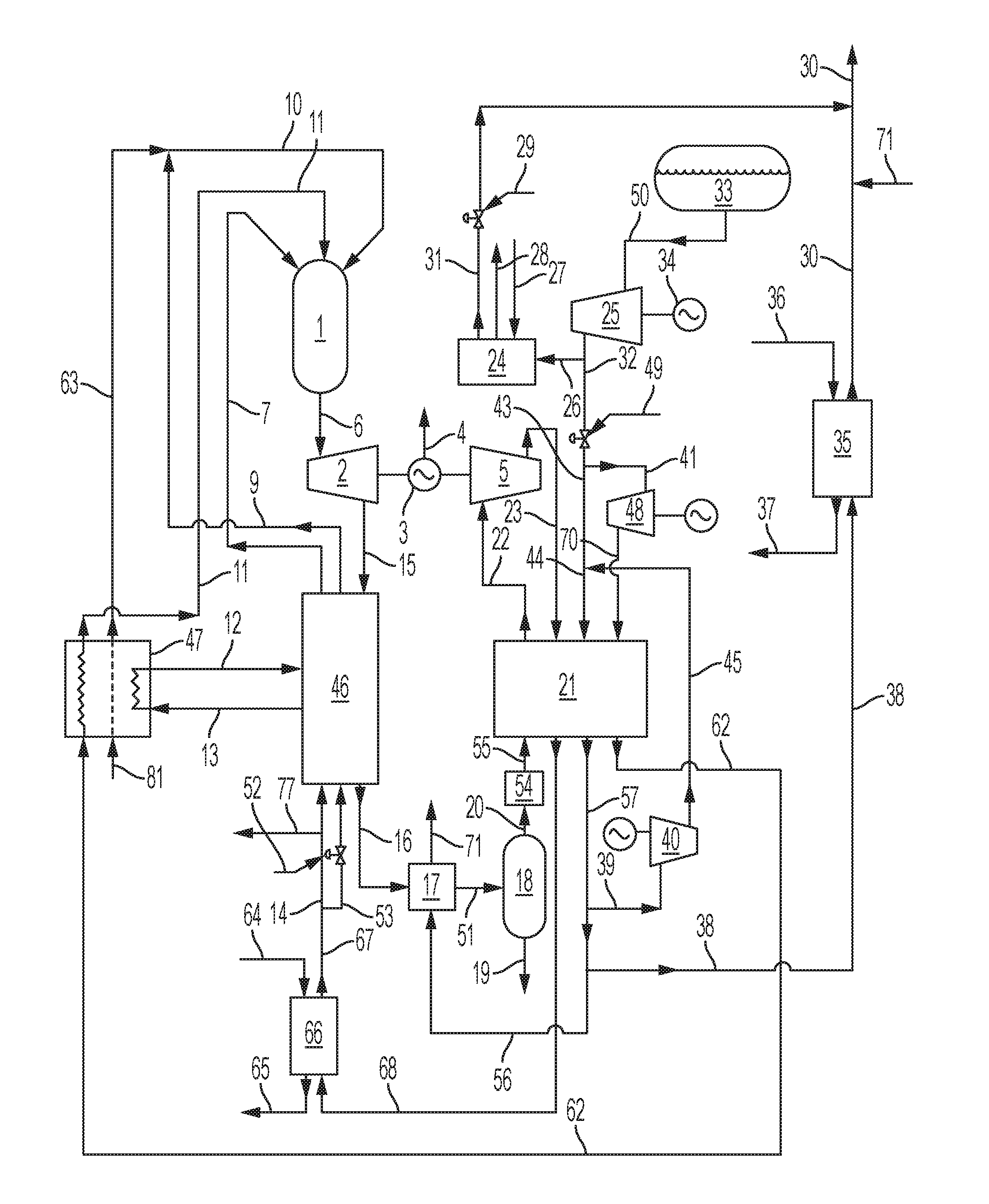
An exemplary embodiment of a power generation system (using a pressurized natural gas fuel supply) integrated with a LNG vaporization and pressurized natural gas supply system is shown in FIG. 3. The discussion of FIG. 3 below illustrates the system and method in relation to a specific embodiment, and certain values and ranges should not be viewed as limiting. Rather, one of skill in the art reviewing the following in light of the present disclosure as a whole will recognize that various values can be changed based upon the specific operating conditions of the power generating system and the LNG vaporization system. The full scope of such ranges is intended to be encompassed by the following discussion, which is exemplary in nature and provided to meet all disclosure requirements.
The power generation system comprises a combustor 1 that combusts the natural gas fuel with oxygen in the presence of a recycled CO.sub.2 working fluid to form a combustion product stream 6 that is rich in CO.sub.2. In this example, the combustion product stream is at a pressure of about 300 bar (30 MPa) and a temperature of about 1150.degree. C. The combustion product stream 6 enters a power turbine 2 driving a turbine electrical generator 3 producing an electrical output 4 together with additional shaft power that is used to drive a liquid CO.sub.2 pump 5. A turbine discharge flow stream 15 at a temperature of about 788.degree. C. and a pressure of about 30 bar (3 MPa) is cooled in an economizer heat exchanger 46 to provide an initially cooled turbine discharge flow stream 16 at a temperature of about 25.degree. C. The initially cooled turbine discharge stream 16 is further cooled in a low temperature heat exchanger 17 and exits as the secondly cooled turbine discharge stream 51 at a temperature of about 4.degree. C. This is achieved against a cooling natural gas stream 56, which is part of the total natural gas stream 57 leaving the CO.sub.2 liquefier heat exchanger 21. The cooling natural gas stream 56 is heated in the low temperature heat exchanger 17 to provide a partial product natural gas stream 71 at a temperature of about 20.degree. C., and this stream joins with the total product pipeline natural gas stream 30 leaving the LNG facility (e.g., at a temperature of about -10.degree. C. or greater). The secondly cooled turbine discharge stream 51 passes into a liquid water separator 18, and a condensed water stream 19 is thereby removed from the secondly cooled turbine discharge stream 51. The separated CO.sub.2 gas stream 20 is dried to a dew point of about -60.degree. C. in a thermally regenerated desiccant drier 54. Other water removal systems, such as pressure swing adsorption (PSA) units also can be used. The dried CO.sub.2 gas stream 55 is cooled to liquefaction, and the liquid CO.sub.2 is sub-cooled to about -50.degree. C. (e.g., -56.degree. C. or greater) in the CO.sub.2 liquefier heat exchanger 21 (e.g., a stainless steel diffusion bonded Heatric type heat exchanger), which simultaneously heats a pre-heated LNG product stream 44 at a pressure of about 68.9 bar (6.89 MPa) to a temperature of about -9.4.degree. C. to form total natural gas stream 57. From the total natural gas stream 57 is divided an LNG heating natural gas fraction 39, which is compressed in an electrically driven blower 40. A thereby formed compressed LNG-heating natural gas stream 45 is mixed with the compressed LNG product stream 43, which is the major fraction of the compressed LNG, to form pre-heated LNG product stream 44, which enters the CO.sub.2 liquefier heat exchanger 21 at a temperature that is above the CO.sub.2 freezing temperature of -56.degree. C. (e.g., to a temperature -55.degree. C. or greater). This arrangement with dry CO.sub.2 and heated LNG can be particularly useful to prevent freezing of the CO.sub.2 to block or damage to the CO.sub.2 liquefier heat exchanger 21.
In the present example, the LNG is stored at a pressure of about 0.08 bar (0.8 MPa) in LNG tank 33. A LNG tank discharge stream 50 is pumped to a pressure of about 70 bar (7 MPa) in LNG pump 25 driven by an electric motor 34. An LNG discharge stream 26 can pass through a water bath heater 24 to provide a bath heated natural gas stream 31 at a temperature of about 15.degree. C. The water bath is heated by a bath fuel gas stream 27 that is burned in air in a draught tube burner with the combustion gases passing through the water and discharging through a bath stack 28. Flow of the compressed LNG stream 32 can be controlled as desired. For example, first control valve 29 and second control valve 49 can be used to determine the routing of the LNG. These, in combination with a variety of further pumps and water bath heaters in the LNG facility (not illustrated), can be used to alternate the flow path of the LNG stream to ensure continuous supply of LNG to the power generation system if the LNG pump 25 goes offline and continuous heating of all the compressed LNG to pipeline conditions if the power generation system goes offline. Such safety back-up provisions are described further herein.
In the present example, the natural gas used as the fuel in the combustor 1 of the power generation system can be drawn from the compressed LNG stream as LNG fuel fraction 41 and pumped to a pressure of about 306 bar (30.6 MPa) in an LNG fuel pump 48 (e.g., a multi-cylinder reciprocating electrically driven pump). A high pressure LNG fuel stream 70 is heated to about -10.degree. C. in the CO.sub.2 liquefier heat exchanger 21 and exits as high pressure natural gas fuel stream 62. Such heating is against the cooling, liquefying and sub-cooling CO.sub.2. The high pressure natural gas fuel stream 62 is then heated in an air separation plant 47 to a temperature of about 230.degree. C. against adiabatically compressed air from air stream 81 using a closed cycle heat transfer fluid, which can be beneficial to prevent leaking of flammable gas into the air separation plant. The exiting, heated, high pressure natural gas stream 11 then proceeds to the combustor 1. The cryogenic air separation plant can include a first stage adiabatic main compressor with a discharge pressure of about 4 bar (0.4 MPa) and a booster compressor where about one third of the first stage compressed air is compressed in two adiabatic stages to about 100 bar (10 MPa). The bulk of the adiabatic heat of compression is transferred firstly to a high pressure recycle CO.sub.2 side stream 13 taken from the high pressure CO.sub.2 recycle stream being heated in the economizer heat exchanger 46. The high pressure recycle CO.sub.2 side stream can be taken at a temperature of about 110.degree. C. and returned as super-heated high pressure recycle CO.sub.2 side stream 12 at a temperature of about 149.degree. C. The adiabatic heat of compression of the two adiabatic stages is secondly used to heat the high pressure natural gas fuel stream 62 to a temperature of about 230.degree. C. to form the heated high pressure natural gas fuel stream 11. The heat of compression is thirdly used to heat the oxygen product stream 63 at a pressure of about 305 bar (30.5 MPa) from the air separation plant to a temperature of about 230.degree. C.
Leaving the cold end of the CO.sub.2 liquefier heat exchanger 21 is a sub-cooled CO.sub.2 recycle stream 22. This stream is compressed to about 306 bar (30.6 MPa) in the liquid CO.sub.2 pump 5, which can be coupled through a gear box directly to the turbine electrical generator 3. Alternatively, a booster compressor (not illustrated) in the cryogenic air separation plant can be directly coupled to the turbine electrical generator 3. As a further alternative, main air compressor in the air separation plant can be directly coupled to the turbine electrical generator. It is preferably for the turbine to be directly loaded with a power demand from one of these alternatives so that in the event of an electrical disconnection from the electricity grid (e.g., arising from a generator trip), there is a load on the generator that will function as a brake since high pressure turbine feed gas will flow until system pressures equalize.
The pressurized sub-cooled CO.sub.2 recycle stream 23 at a temperature of about -43.degree. C. is then heated in the CO.sub.2 liquefier heat exchanger 21 to a temperature of about 5.5.degree. C. The high pressure recycle CO.sub.2 stream 68 is heated to a temperature of about 25.degree. C. in a supplemental CO.sub.2 heat exchanger 66 to form a pre-heated high pressure recycle CO.sub.2 stream 67. A heated, closed cycle heat transfer fluid stream 64 at a temperature of about 40.degree. C. is cooled to a temperature of about 10.degree. C. to exit as cooled heat transfer fluid stream 65. In a similar fashion, a total natural gas stream fraction 38 at a temperature of about -9.4.degree. C. can be passed through a secondary natural gas heat exchanger 35 to be heated against a second heated, closed cycle heat transfer fluid stream 36 at about 40.degree. C. A secondary cooled heat transfer fluid stream 37 exits at a temperature of about 10.degree. C.
The pre-heated high pressure recycle CO.sub.2 stream 67 leaving supplemental CO.sub.2 heat exchanger 66 is divided into a first high pressure recycle CO.sub.2 fraction 14 and a second high pressure recycle CO.sub.2 fraction 53, which both pass through the economizer heat exchanger 46 and exit at a temperature of about 752.degree. C. Recycle CO.sub.2 fraction control valve 52 at the cold end of economizer heat exchanger 46 controls the flow ratio of the first CO.sub.2 fraction 14 to the second CO.sub.2 fraction 53. The heated, first CO.sub.2 fraction stream 7 is delivered to the combustor 1 as the working fluid. The heated, second CO.sub.2 fraction stream 9 mixes with the oxygen product stream 63 to give a 30% oxygen, 70% CO.sub.2 molar ratio in the oxidant stream 10 entering the combustor 1, which moderates the adiabatic flame temperature to a value below about 3000.degree. C. The net CO.sub.2 product derived from the combusted fuel is available as a pipeline ready CO.sub.2 product stream 77 at a pressure of about 305 bar (30.5 MPa) and a temperature of about 25.degree. C.
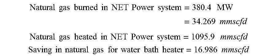
Performance values based on a 250 MW net electrical output were calculated for the above exemplary integrated system using pure methane from the LNG source as the fuel for the combustor. Calculated values were as follows:
.times..times..times..times..times..times..times..times..times..times..ti- mes..times..times..times..times..times..times..times. ##EQU00001## .times..times..times..times..times..times..times..times..times..times..ti- mes..times..times..times. ##EQU00001.2## .times..times..times..times..times..times..times..times..times..times..ti- mes..times..times..times..times..times. ##EQU00001.3##
Based on the foregoing, modeling was used to calculate efficiencies for a 1000 MW net electrical power generating system with an integrated LNG system as discussed above providing 1000 mmscfd natural gas flow rate at 68 bar (6.8 MPa) delivered to a pipeline at 15.degree. C. Calculated overall efficiency was 68.06%. Calculated overall efficiency with a zero LNG flow rate to the 1000 MW power plant was 58.87%. In still a further embodiment modeled using Aspen Plus, a system and method according to the present disclosure used a methane fuel in the combustor, a turbine, a first heat exchanger (which was a series of three heat exchange units), a water separator, a second heat exchanger where CO.sub.2 was liquefied against LNG to produce NG (with a side stream being used to pre-heat the LNG), a single pump to pressurize the recycle CO.sub.2 stream, and recovered heat from an air separation plant to supplement heating of the recycle CO.sub.2 stream. In the model of such embodiment, the overall efficiency of the integrated power generating and LNG vaporizing system and method was 65.7%. All of the above efficiency calculations encompass the complete capture of all excess CO.sub.2 from combustion.
The benefit is further seen in relation to conventional LNG re-gasification systems wherein, typically, about 1.4% of the LNG that is processed is burned to provide heating, such as in the submerged burner described in relation to FIG. 2, for the remaining 98.6% of the processed LNG. This duty is imposed without any added benefit. According to the present disclosure, however, a 250 MWe power generating system, for example, can be integrated with a LNG re-gasification plant. In such example, the LNG plant can reheat approximately 10.8 B m.sup.3/year of LNG while burning approximately 3.1% to provide the heat. Because of the integration, although total gas sendout is reduced to 96.9% of the total amount processed, the increased duty fuels the generation of the electricity in the 250 MW power plant. Beneficially, such systems can be scaled as desired to increased or decreased capacity in relation to processed LNG and/or produced electricity.
Many modifications and other embodiments of the inventions set forth herein will come to mind to one skilled in the art to which these inventions pertain having the benefit of the teachings presented in the foregoing descriptions. Therefore, it is to be understood that the inventions are not to be limited to the specific embodiments disclosed and that modifications and other embodiments are intended to be included within the scope of the appended claims. Although specific terms are employed herein, they are used in a generic and descriptive sense only and not for purposes of limitation.
DESCRIPTION OF THE REFERENCE NUMERALS
1 combustor 2 power turbine 3 turbine electrical generator 4 electrical output 5 liquid CO.sub.2 pump 6 combustion product stream 7 heated, first CO.sub.2 fraction stream 9 heated second CO.sub.2 fraction stream 10 oxidant stream 11 natural gas stream 12 super-heated high pressure recycle CO.sub.2 side stream 13 high pressure recycle CO.sub.2 side stream 14 first high pressure recycle CO.sub.2 fraction 15 turbine discharge flow stream 16 initially cooled turbine discharge flow stream 17 low temperature heat exchanger 18 liquid water separator 19 condensed water stream 20 separated CO.sub.2 gas stream 21 CO.sub.2 liquefier heat exchanger 22 sub-cooled CO.sub.2 recycle stream 23 pressurized sub-cooled CO.sub.2 recycle stream 24 water bath heater 25 LNG pump 26 LNG discharge stream 27 bath fuel gas stream 28 bath stack 29 first control valve 30 total product pipeline natural gas stream 31 bath heated natural gas stream 32 compressed LNG stream 33 LNG tank 34 electric motor 35 secondary natural gas heat exchanger 36 secondary heated, closed cycle heat transfer fluid 37 secondary cooled heat transfer fluid 38 total natural gas stream fraction 39 LNG-heating natural gas fraction 40 blower 41 LNG fuel fraction 43 compressed LNG product stream 44 pre-heated LNG product stream 45 compressed LNG-heating natural gas stream 46 economizer heat exchanger 47 air separation plant 48 LNG fuel pump 49 second control valve 50 LNG tank discharge stream 51 secondly cooled turbine discharge stream 52 recycle CO.sub.2 control valve 53 second high pressure recycle CO.sub.2 fraction 54 thermally regenerated desiccant drier 55 dried CO.sub.2 gas stream 56 cooling natural gas stream 57 total natural gas stream 62 high pressure natural gas fuel stream 63 oxygen product stream 64 heated, closed cycle heat transfer fluid stream 65 cooled heat transfer fluid stream 66 supplemental CO.sub.2 heat exchanger 67 pre-heated high pressure recycle CO.sub.2 stream 68 high pressure recycle CO.sub.2 stream 70 high pressure LNG fuel stream 71 partial product natural gas stream 77 CO.sub.2 product stream 100 tank 101 pump 102 water bath vaporizer 103 filter 104 burner pressure blower 105 boil-off blower 106 boil-off compressor 107 atmospheric air line 109 air line 110 LNG tank boil-off line 111 boil-off compressor line 112 boil-off stream 113 NG burner fuel line 114 compressed boil-off NG stream 115 product natural gas stream 116 total natural gas pipeline flow stream 117 pressurized fuel gas stream 119 LNG supply line 120 burner 121 vent line 210a LNG supply 210b heated LNG supply 221 heat exchanger 239 supplement NG stream 240 blower 257 NG stream 258 product NG stream
* * * * *
References
uspto.report is an independent third-party trademark research tool that is not affiliated, endorsed, or sponsored by the United States Patent and Trademark Office (USPTO) or any other governmental organization. The information provided by uspto.report is based on publicly available data at the time of writing and is intended for informational purposes only.
While we strive to provide accurate and up-to-date information, we do not guarantee the accuracy, completeness, reliability, or suitability of the information displayed on this site. The use of this site is at your own risk. Any reliance you place on such information is therefore strictly at your own risk.
All official trademark data, including owner information, should be verified by visiting the official USPTO website at www.uspto.gov. This site is not intended to replace professional legal advice and should not be used as a substitute for consulting with a legal professional who is knowledgeable about trademark law.